EP3211732A1 - Connector and method for producing a connector - Google Patents
Connector and method for producing a connector Download PDFInfo
- Publication number
- EP3211732A1 EP3211732A1 EP16157213.6A EP16157213A EP3211732A1 EP 3211732 A1 EP3211732 A1 EP 3211732A1 EP 16157213 A EP16157213 A EP 16157213A EP 3211732 A1 EP3211732 A1 EP 3211732A1
- Authority
- EP
- European Patent Office
- Prior art keywords
- thermoset
- injection
- molding
- premold
- seconds
- Prior art date
- Legal status (The legal status is an assumption and is not a legal conclusion. Google has not performed a legal analysis and makes no representation as to the accuracy of the status listed.)
- Granted
Links
Images
Classifications
-
- H—ELECTRICITY
- H01—ELECTRIC ELEMENTS
- H01R—ELECTRICALLY-CONDUCTIVE CONNECTIONS; STRUCTURAL ASSOCIATIONS OF A PLURALITY OF MUTUALLY-INSULATED ELECTRICAL CONNECTING ELEMENTS; COUPLING DEVICES; CURRENT COLLECTORS
- H01R13/00—Details of coupling devices of the kinds covered by groups H01R12/70 or H01R24/00 - H01R33/00
- H01R13/46—Bases; Cases
- H01R13/52—Dustproof, splashproof, drip-proof, waterproof, or flameproof cases
-
- B—PERFORMING OPERATIONS; TRANSPORTING
- B29—WORKING OF PLASTICS; WORKING OF SUBSTANCES IN A PLASTIC STATE IN GENERAL
- B29C—SHAPING OR JOINING OF PLASTICS; SHAPING OF MATERIAL IN A PLASTIC STATE, NOT OTHERWISE PROVIDED FOR; AFTER-TREATMENT OF THE SHAPED PRODUCTS, e.g. REPAIRING
- B29C45/00—Injection moulding, i.e. forcing the required volume of moulding material through a nozzle into a closed mould; Apparatus therefor
- B29C45/16—Making multilayered or multicoloured articles
- B29C45/1671—Making multilayered or multicoloured articles with an insert
-
- B—PERFORMING OPERATIONS; TRANSPORTING
- B29—WORKING OF PLASTICS; WORKING OF SUBSTANCES IN A PLASTIC STATE IN GENERAL
- B29C—SHAPING OR JOINING OF PLASTICS; SHAPING OF MATERIAL IN A PLASTIC STATE, NOT OTHERWISE PROVIDED FOR; AFTER-TREATMENT OF THE SHAPED PRODUCTS, e.g. REPAIRING
- B29C45/00—Injection moulding, i.e. forcing the required volume of moulding material through a nozzle into a closed mould; Apparatus therefor
- B29C45/16—Making multilayered or multicoloured articles
- B29C45/1657—Making multilayered or multicoloured articles using means for adhering or bonding the layers or parts to each other
-
- B—PERFORMING OPERATIONS; TRANSPORTING
- B29—WORKING OF PLASTICS; WORKING OF SUBSTANCES IN A PLASTIC STATE IN GENERAL
- B29C—SHAPING OR JOINING OF PLASTICS; SHAPING OF MATERIAL IN A PLASTIC STATE, NOT OTHERWISE PROVIDED FOR; AFTER-TREATMENT OF THE SHAPED PRODUCTS, e.g. REPAIRING
- B29C45/00—Injection moulding, i.e. forcing the required volume of moulding material through a nozzle into a closed mould; Apparatus therefor
- B29C45/16—Making multilayered or multicoloured articles
- B29C45/1676—Making multilayered or multicoloured articles using a soft material and a rigid material, e.g. making articles with a sealing part
-
- B—PERFORMING OPERATIONS; TRANSPORTING
- B29—WORKING OF PLASTICS; WORKING OF SUBSTANCES IN A PLASTIC STATE IN GENERAL
- B29C—SHAPING OR JOINING OF PLASTICS; SHAPING OF MATERIAL IN A PLASTIC STATE, NOT OTHERWISE PROVIDED FOR; AFTER-TREATMENT OF THE SHAPED PRODUCTS, e.g. REPAIRING
- B29C71/00—After-treatment of articles without altering their shape; Apparatus therefor
- B29C71/02—Thermal after-treatment
-
- H—ELECTRICITY
- H01—ELECTRIC ELEMENTS
- H01R—ELECTRICALLY-CONDUCTIVE CONNECTIONS; STRUCTURAL ASSOCIATIONS OF A PLURALITY OF MUTUALLY-INSULATED ELECTRICAL CONNECTING ELEMENTS; COUPLING DEVICES; CURRENT COLLECTORS
- H01R13/00—Details of coupling devices of the kinds covered by groups H01R12/70 or H01R24/00 - H01R33/00
- H01R13/40—Securing contact members in or to a base or case; Insulating of contact members
- H01R13/405—Securing in non-demountable manner, e.g. moulding, riveting
-
- H—ELECTRICITY
- H01—ELECTRIC ELEMENTS
- H01R—ELECTRICALLY-CONDUCTIVE CONNECTIONS; STRUCTURAL ASSOCIATIONS OF A PLURALITY OF MUTUALLY-INSULATED ELECTRICAL CONNECTING ELEMENTS; COUPLING DEVICES; CURRENT COLLECTORS
- H01R13/00—Details of coupling devices of the kinds covered by groups H01R12/70 or H01R24/00 - H01R33/00
- H01R13/46—Bases; Cases
- H01R13/52—Dustproof, splashproof, drip-proof, waterproof, or flameproof cases
- H01R13/5216—Dustproof, splashproof, drip-proof, waterproof, or flameproof cases characterised by the sealing material, e.g. gels or resins
-
- H—ELECTRICITY
- H01—ELECTRIC ELEMENTS
- H01R—ELECTRICALLY-CONDUCTIVE CONNECTIONS; STRUCTURAL ASSOCIATIONS OF A PLURALITY OF MUTUALLY-INSULATED ELECTRICAL CONNECTING ELEMENTS; COUPLING DEVICES; CURRENT COLLECTORS
- H01R43/00—Apparatus or processes specially adapted for manufacturing, assembling, maintaining, or repairing of line connectors or current collectors or for joining electric conductors
- H01R43/005—Apparatus or processes specially adapted for manufacturing, assembling, maintaining, or repairing of line connectors or current collectors or for joining electric conductors for making dustproof, splashproof, drip-proof, waterproof, or flameproof connection, coupling, or casing
-
- H—ELECTRICITY
- H01—ELECTRIC ELEMENTS
- H01R—ELECTRICALLY-CONDUCTIVE CONNECTIONS; STRUCTURAL ASSOCIATIONS OF A PLURALITY OF MUTUALLY-INSULATED ELECTRICAL CONNECTING ELEMENTS; COUPLING DEVICES; CURRENT COLLECTORS
- H01R43/00—Apparatus or processes specially adapted for manufacturing, assembling, maintaining, or repairing of line connectors or current collectors or for joining electric conductors
- H01R43/18—Apparatus or processes specially adapted for manufacturing, assembling, maintaining, or repairing of line connectors or current collectors or for joining electric conductors for manufacturing bases or cases for contact members
-
- H—ELECTRICITY
- H01—ELECTRIC ELEMENTS
- H01R—ELECTRICALLY-CONDUCTIVE CONNECTIONS; STRUCTURAL ASSOCIATIONS OF A PLURALITY OF MUTUALLY-INSULATED ELECTRICAL CONNECTING ELEMENTS; COUPLING DEVICES; CURRENT COLLECTORS
- H01R43/00—Apparatus or processes specially adapted for manufacturing, assembling, maintaining, or repairing of line connectors or current collectors or for joining electric conductors
- H01R43/20—Apparatus or processes specially adapted for manufacturing, assembling, maintaining, or repairing of line connectors or current collectors or for joining electric conductors for assembling or disassembling contact members with insulating base, case or sleeve
- H01R43/24—Assembling by moulding on contact members
-
- B—PERFORMING OPERATIONS; TRANSPORTING
- B29—WORKING OF PLASTICS; WORKING OF SUBSTANCES IN A PLASTIC STATE IN GENERAL
- B29C—SHAPING OR JOINING OF PLASTICS; SHAPING OF MATERIAL IN A PLASTIC STATE, NOT OTHERWISE PROVIDED FOR; AFTER-TREATMENT OF THE SHAPED PRODUCTS, e.g. REPAIRING
- B29C45/00—Injection moulding, i.e. forcing the required volume of moulding material through a nozzle into a closed mould; Apparatus therefor
- B29C45/16—Making multilayered or multicoloured articles
- B29C45/1676—Making multilayered or multicoloured articles using a soft material and a rigid material, e.g. making articles with a sealing part
- B29C2045/1678—Making multilayered or multicoloured articles using a soft material and a rigid material, e.g. making articles with a sealing part first moulding the soft material
-
- B—PERFORMING OPERATIONS; TRANSPORTING
- B29—WORKING OF PLASTICS; WORKING OF SUBSTANCES IN A PLASTIC STATE IN GENERAL
- B29C—SHAPING OR JOINING OF PLASTICS; SHAPING OF MATERIAL IN A PLASTIC STATE, NOT OTHERWISE PROVIDED FOR; AFTER-TREATMENT OF THE SHAPED PRODUCTS, e.g. REPAIRING
- B29C71/00—After-treatment of articles without altering their shape; Apparatus therefor
- B29C71/02—Thermal after-treatment
- B29C2071/027—Tempering, i.e. heating an object to a high temperature and quenching it
-
- B—PERFORMING OPERATIONS; TRANSPORTING
- B29—WORKING OF PLASTICS; WORKING OF SUBSTANCES IN A PLASTIC STATE IN GENERAL
- B29C—SHAPING OR JOINING OF PLASTICS; SHAPING OF MATERIAL IN A PLASTIC STATE, NOT OTHERWISE PROVIDED FOR; AFTER-TREATMENT OF THE SHAPED PRODUCTS, e.g. REPAIRING
- B29C45/00—Injection moulding, i.e. forcing the required volume of moulding material through a nozzle into a closed mould; Apparatus therefor
- B29C45/14—Injection moulding, i.e. forcing the required volume of moulding material through a nozzle into a closed mould; Apparatus therefor incorporating preformed parts or layers, e.g. injection moulding around inserts or for coating articles
- B29C45/14639—Injection moulding, i.e. forcing the required volume of moulding material through a nozzle into a closed mould; Apparatus therefor incorporating preformed parts or layers, e.g. injection moulding around inserts or for coating articles for obtaining an insulating effect, e.g. for electrical components
-
- B—PERFORMING OPERATIONS; TRANSPORTING
- B29—WORKING OF PLASTICS; WORKING OF SUBSTANCES IN A PLASTIC STATE IN GENERAL
- B29K—INDEXING SCHEME ASSOCIATED WITH SUBCLASSES B29B, B29C OR B29D, RELATING TO MOULDING MATERIALS OR TO MATERIALS FOR MOULDS, REINFORCEMENTS, FILLERS OR PREFORMED PARTS, e.g. INSERTS
- B29K2063/00—Use of EP, i.e. epoxy resins or derivatives thereof, as moulding material
-
- B—PERFORMING OPERATIONS; TRANSPORTING
- B29—WORKING OF PLASTICS; WORKING OF SUBSTANCES IN A PLASTIC STATE IN GENERAL
- B29K—INDEXING SCHEME ASSOCIATED WITH SUBCLASSES B29B, B29C OR B29D, RELATING TO MOULDING MATERIALS OR TO MATERIALS FOR MOULDS, REINFORCEMENTS, FILLERS OR PREFORMED PARTS, e.g. INSERTS
- B29K2067/00—Use of polyesters or derivatives thereof, as moulding material
- B29K2067/006—PBT, i.e. polybutylene terephthalate
-
- B—PERFORMING OPERATIONS; TRANSPORTING
- B29—WORKING OF PLASTICS; WORKING OF SUBSTANCES IN A PLASTIC STATE IN GENERAL
- B29K—INDEXING SCHEME ASSOCIATED WITH SUBCLASSES B29B, B29C OR B29D, RELATING TO MOULDING MATERIALS OR TO MATERIALS FOR MOULDS, REINFORCEMENTS, FILLERS OR PREFORMED PARTS, e.g. INSERTS
- B29K2077/00—Use of PA, i.e. polyamides, e.g. polyesteramides or derivatives thereof, as moulding material
-
- B—PERFORMING OPERATIONS; TRANSPORTING
- B29—WORKING OF PLASTICS; WORKING OF SUBSTANCES IN A PLASTIC STATE IN GENERAL
- B29K—INDEXING SCHEME ASSOCIATED WITH SUBCLASSES B29B, B29C OR B29D, RELATING TO MOULDING MATERIALS OR TO MATERIALS FOR MOULDS, REINFORCEMENTS, FILLERS OR PREFORMED PARTS, e.g. INSERTS
- B29K2105/00—Condition, form or state of moulded material or of the material to be shaped
- B29K2105/06—Condition, form or state of moulded material or of the material to be shaped containing reinforcements, fillers or inserts
- B29K2105/16—Fillers
-
- B—PERFORMING OPERATIONS; TRANSPORTING
- B29—WORKING OF PLASTICS; WORKING OF SUBSTANCES IN A PLASTIC STATE IN GENERAL
- B29K—INDEXING SCHEME ASSOCIATED WITH SUBCLASSES B29B, B29C OR B29D, RELATING TO MOULDING MATERIALS OR TO MATERIALS FOR MOULDS, REINFORCEMENTS, FILLERS OR PREFORMED PARTS, e.g. INSERTS
- B29K2105/00—Condition, form or state of moulded material or of the material to be shaped
- B29K2105/24—Condition, form or state of moulded material or of the material to be shaped crosslinked or vulcanised
- B29K2105/243—Partially cured
-
- B—PERFORMING OPERATIONS; TRANSPORTING
- B29—WORKING OF PLASTICS; WORKING OF SUBSTANCES IN A PLASTIC STATE IN GENERAL
- B29K—INDEXING SCHEME ASSOCIATED WITH SUBCLASSES B29B, B29C OR B29D, RELATING TO MOULDING MATERIALS OR TO MATERIALS FOR MOULDS, REINFORCEMENTS, FILLERS OR PREFORMED PARTS, e.g. INSERTS
- B29K2995/00—Properties of moulding materials, reinforcements, fillers, preformed parts or moulds
- B29K2995/0003—Properties of moulding materials, reinforcements, fillers, preformed parts or moulds having particular electrical or magnetic properties, e.g. piezoelectric
- B29K2995/0005—Conductive
-
- B—PERFORMING OPERATIONS; TRANSPORTING
- B29—WORKING OF PLASTICS; WORKING OF SUBSTANCES IN A PLASTIC STATE IN GENERAL
- B29L—INDEXING SCHEME ASSOCIATED WITH SUBCLASS B29C, RELATING TO PARTICULAR ARTICLES
- B29L2031/00—Other particular articles
- B29L2031/26—Sealing devices, e.g. packaging for pistons or pipe joints
-
- B—PERFORMING OPERATIONS; TRANSPORTING
- B29—WORKING OF PLASTICS; WORKING OF SUBSTANCES IN A PLASTIC STATE IN GENERAL
- B29L—INDEXING SCHEME ASSOCIATED WITH SUBCLASS B29C, RELATING TO PARTICULAR ARTICLES
- B29L2031/00—Other particular articles
- B29L2031/34—Electrical apparatus, e.g. sparking plugs or parts thereof
- B29L2031/36—Plugs, connectors, or parts thereof
-
- H—ELECTRICITY
- H01—ELECTRIC ELEMENTS
- H01R—ELECTRICALLY-CONDUCTIVE CONNECTIONS; STRUCTURAL ASSOCIATIONS OF A PLURALITY OF MUTUALLY-INSULATED ELECTRICAL CONNECTING ELEMENTS; COUPLING DEVICES; CURRENT COLLECTORS
- H01R13/00—Details of coupling devices of the kinds covered by groups H01R12/70 or H01R24/00 - H01R33/00
- H01R13/46—Bases; Cases
- H01R13/52—Dustproof, splashproof, drip-proof, waterproof, or flameproof cases
- H01R13/521—Sealing between contact members and housing, e.g. sealing insert
Definitions
- the present application relates to a method of producing a connector having at least one conductor and at least one contact pin which are electrically connected at a contact point, and a corresponding connector.
- Connectors are used today in all technological areas. They allow to connect different electrical components in a simple manner even after assembly. Further, many connectors are removable, so that an existing connection can be separated easily, for example during maintenance or repair.
- a connector comprises an electrical connection around which a thermoplast is injection-molded.
- the connector is subject to environmental conditions, for example humidity or liquids.
- humidity and liquids can enter e.g. along the insulating sheath of the conductor or even within the conductor. Since these interspaces are very small, the entering of humidity and liquids may be accelerated by capillary action. Therefore, humidity or liquids can slowly advance through the connector and can potentially reach the connector side and thus electrical contacts of connected electrical components which can thereby be damaged, e.g. due to a short.
- the tight sealing of conductors with multiple wires - in contrast to a single solid wire - poses a significant challenge.
- thermoset instead of a thermoplast, which may render a better material connection to the electrical element.
- a thermoset material is very hard and stiff after curing and does not allow to provide any flexible elements, for example a spring hook. Therefore, such solution is suitable only for very few applications.
- the object is achieved by a method for producing a connector using injection-molding, the method comprising the steps: providing at least one conductor and at least one contact pin which are electrically connected at a contact point, producing a thermoset premold from a thermoset using injection-molding, wherein the thermoset is injection-molded around at least a first section of the at least one conductor and/or around at least a second section of the at least one contact pin, and injection-molding of a thermoplast on the thermoset premold, wherein the step of injection-molding takes place before the thermoset premold has obtained a degree of curing of 90%.
- the conductor and the contact pin receive a thermoset via injection-molding, so that the resulting thermoset premold encloses at least a first section of the at least one connector and/or at least a second section of the at least one contact pin, in particular enclosing a section of the conductor and a section of the contact pin including the contact point.
- a thermoplast Prior to the thermoset premold reaching a degree of curing of 90% a thermoplast is injection-molded onto the thermoset premold. This early injection-molding provides a good adhesion or attachment between the thermoset and the thermoplast.
- the resulting thermoplast shape on the thermoset premold can be considered as a thermoplast overmold or a thermoplast aftermold.
- degree of curing is known to the skilled person in the field of material science, in particular in the field of producing electrical connectors via injection-molding. However, in particular, the expression is to be understood in the sense of a chemical cross-linking or a chemical cross-linking of molecules. The expression “degree of curing” can also be understood as the degree of polymer cross-linking by applying thermal energy.
- the cross-linking may in particular be understood as a chaining or concatenation of simple molecules to complex three dimensional macro molecule chains.
- thermoset premold a surprisingly good cross-linking between the thermoset premold and the thermoplast can be achieved when applying the thermoplast via injection-molding before, in particular well before, the thermoset has cured.
- the invention is applicable to male contact pins as well as female contact pins having openings.
- thermoset premold is produced in a first injection-molding tool and the thermoplast is injection-molded around the thermoset premold in a second injection-molding tool, wherein the thermoset premold is removed from the first injection-molding tool.
- the step of injection-molding is performed before the thermoset premold has reached a degree of curing of 80%, preferably 70%, more preferably 67% and in particular 64%.
- thermoset This refinement allows for a good adhesion or attachment between the thermoset and the thermoplast.
- the step of injection-molding is performed after the thermoset premold has reached a degree of curing of 40%, preferably 50%, more preferably 55% and in particular 57%.
- thermoset premold must have a sufficient form stability or shape stability, before the transfer to the injection-molding step can be performed, in particular so that the thermoset premold can be removed from the first injection-molding tool without being damaged.
- the given values provide a starting point for a weighting between having a sufficient form stability without the curing having progressed too far.
- the step of injection-molding is performed after the thermoset premold has reached a degree of curing of 57.5%, but before the thermoset premold has reached a degree of curing of 63.5%.
- thermoset premold has at least 50%, preferably at least 60%, more preferably at least 70% and in particular more than 75% of its thermal energy which was present right after the step of producing.
- thermoset premold a cooling of the thermoset premold is avoided as much as this is practical from a process perspective.
- a cooling phase is avoided, in particular an active cooling phase involving a cooling medium is avoided.
- the step of injection-molding is performed when the thermoset premold has not more than 99%, preferably not more than 95%, more preferably not more than 90% and in particular not more than 85% of its thermal energy which was present right after the step of producing.
- thermoset premold may require, in some embodiments, a temperature between 160 °C and 190 °C, whereas the injection-molding using the thermoplast takes place at a temperature between 75 °C and 100 °C.
- thermoset premold has a temperature of at least 100 °C, preferably at least 125 °C, more preferably at least 150 °C and in particular at least 160 °C.
- thermoset and the thermoplast and can be achieved, as explained above, by avoiding a cooling phase.
- thermoset premold has a temperature of not more than 250 °C, preferably not more than 225 °C, more preferably not more than 200 °C and in particular not more than 190 °C.
- the step of producing lasts at least 8 seconds, preferably at least 9 seconds, more preferably at least 10 seconds and in particular at least 11 seconds.
- the step of production lasts not more than 20 seconds, preferably not more than 18 seconds, more preferably not more than 16 seconds, and in particular not more than 14 seconds.
- the time between the end of the step of producing and the start of the step of injection-molding is not more than 30 seconds, preferably not more than 20 seconds, more preferably not more than 15 seconds and in particular not more than 10 seconds.
- thermoset premold progresses even after the thermoset premold has been removed from the first injection-molding tool. The reason is that the thermoset premold still has a significant amount of thermal energy even after the removal which advances the curing and thus the process of creating cross-links as explained above. This refinement may avoid that despite an early removal of the thermoset premold from the first injection-molding tool the curing continues as time passes by and reaches a degree of curing that does not allow for a good bonding between the thermoset and the thermoplast anymore.
- thermoset is an epoxy resin, in particular an epoxy resin molding material for injection-molding.
- thermoplast is a filled PA66 or PBT material and is selected in particular from the group comprising PA66 GF35, PBT GF30, and similar materials.
- step of injection-molding is followed by a step of tempering or malleablizing.
- This refinement may allow for an improved bonding between the thermoset and the thermoplast for particular combinations of materials.
- This step can also be understood as a post-curing.
- a connector comprising at least one conductor and at least one contact pin which are electrically connected to one another at a contact point, wherein at least a first section of the at least one conductor and/or at least a second section of the at least one contact pin is surrounded by a thermoset applied via injection-molding, wherein a thermoplast is injection-molded onto the thermoset.
- Such connector may provide the advantage that humidity or liquids are hindered to advance within the connector to the connector side. Further, due to the injection-molding using the thermoplast flexible elements can be provided. A good adhesion or attachment between the thermoset and the thermoplast and the resulting sealing can be obtained using the process described above.
- the degree of curing of the thermoset is less than 95%, preferably less than 90%, more preferably less than 85% and in particular less than 80%.
- thermoset the full curing of the thermoset is not being waited for, but the injection-molding using the thermoplast is performed rather early.
- thermoset at a joint face - also called (phase) surface or boundary (surface) - between the thermoset and the thermoplast is at least substantially the same as a second degree of curing of the thermoset at a location which is at a distance from the joint face, in particular at a maximum distance from the joint face.
- thermoset premold Having a substantially similar degree of curing of the thermoset at different locations of the thermoset premold may be achieved, as explained above, by avoiding a cooling phase, in particular an active cooling phase.
- the conductor comprises a plurality of wires, i.e., comprising a plurality of individual wires, wherein the conductor is in particular a stranded wire.
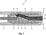
- Fig. 1 shows a connector 10 having a conductor 12 and a contact pin 14.
- the conductor 12 comprises a plurality of single wires 16 which extend from the nonconducting conductor sheath 18 within the connector 10.
- the side of the connector 10 exposing the contact pin 14 for connection to another electrical component is called connector side 29.
- a connector will have multiple contact pins each with a corresponding conductor.
- the conductor 12 is electrically connected to the contact pin 14 at a contact point 20.
- the contact point 20 is provided as a soldering point or welding point. Other preferred embodiments may use a crimp-connection.
- the contact point 20 can also be obtained in other ways.
- thermoset premold 24 The shape of the thermoset which results from injection-molding the thermoset around a section of the at least one conductor 12 and/or the section of the at least one contact pin 14 is called thermoset premold 24.
- thermoset premold 24 can comprise a plurality of separate individual parts. Also, there are embodiments where the thermoset premold 24 does not surround the contact pin 14, the contact point 20 nor the exposed sections of the single wires 16. However, it is believed to be advantageous from a process perspective, if the thermoset is injection-molded around the multiple elements as shown.
- thermoset 22 or the thermoset premold 24 receives a thermoplast 26 cover via injection-molding. While the thermoset 22 is very hard and stiff without any flexible properties when the production of the connector 10 is finished, the thermoplast 26 allows to provide flexible elements, for example a spring hook (not shown).
- Fig. 1 shows five different joint faces between the different materials which are indicated with reference numerals 1 to 5.
- the joint faces are present between the following elements: 1) outside of conductor sheath 18 and thermoset 22, 2) inside of conductor sheath 18 and thermoset 22, 3) single wires 16 and thermoset 22, 4) contact pin 14 and thermoset 22, and 5) thermoset 22 and thermoplast 26.
- the joint faces 1 and 2 will typically not provide a good sealing, since neither the neither thermoset 22 nor the thermoplast 26 have a fully tight bonding to the conductor sheath 18. However, a good sealing is provided at the joint face 3, since the thermoset 22 has a low viscosity during injection-molding and also has good adhesion or attachment characteristics on metal. In addition, the thermoset 22 may also be pulled into very small cavities due to capillary action.
- thermoset 22 has good adhesion or attachment characteristics on metal.
- a good bonding between the thermoset 22 and the thermoplast 26 is present at joint face 5, because the thermoplast 26 is applied to the thermoset premold 24 before the thermoset premold 24 is fully cured.
- thermoset 22 For the shown embodiment of the connector 10 a first degree of curing of the thermoset 22 at the joint face 10, an exemplary location is indicated with reference numeral 30, between the thermoset 22 and the thermoplast 26 is at least substantially the same as a second degree of curing of the thermoset 22 at a location 32 which is at a distance from the joint face 5.
- location 32 is at a maximum distance from the joint face 5, because the joint face 5 surrounds the elements enclosed therein in the manner of a cylinder.
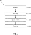
- Fig. 2 shows a method for producing a connector 10 using injection-molding.
- the method starts with providing S10 at least one conductor 12 and at least one contact pin 14, which are electrically connected at a contact point 20.
- the thermoset premold 24 is produced from a thermoset 22 using injection-molding, wherein the thermoset 22 is applied around at least a first section of the at least one conductor 12 and/or at least a second section of the at least one contact pin 14.
- a step of injection-molding S14 of a thermoplast 26 on the thermoset premold 24 follows.
- the step of injection-molding S14 takes place before the thermoset premold 24 has reached a degree of curing of 90%.
- the step of injection-molding S14 may be followed by a step of annealing S16. Further preferred embodiments of the method 40 can be derived from the above explanations.
Landscapes
- Engineering & Computer Science (AREA)
- Manufacturing & Machinery (AREA)
- Mechanical Engineering (AREA)
- Physics & Mathematics (AREA)
- Thermal Sciences (AREA)
- Chemical & Material Sciences (AREA)
- Dispersion Chemistry (AREA)
- Injection Moulding Of Plastics Or The Like (AREA)
- Connector Housings Or Holding Contact Members (AREA)
Abstract
Description
- The present application relates to a method of producing a connector having at least one conductor and at least one contact pin which are electrically connected at a contact point, and a corresponding connector.
- Connectors are used today in all technological areas. They allow to connect different electrical components in a simple manner even after assembly. Further, many connectors are removable, so that an existing connection can be separated easily, for example during maintenance or repair.
- A connector comprises an electrical connection around which a thermoplast is injection-molded. During use the connector is subject to environmental conditions, for example humidity or liquids. While the connector side can usually be sealed well, e.g. using radial sealing rings, humidity and liquids can enter e.g. along the insulating sheath of the conductor or even within the conductor. Since these interspaces are very small, the entering of humidity and liquids may be accelerated by capillary action. Therefore, humidity or liquids can slowly advance through the connector and can potentially reach the connector side and thus electrical contacts of connected electrical components which can thereby be damaged, e.g. due to a short. In particular the tight sealing of conductors with multiple wires - in contrast to a single solid wire - poses a significant challenge.
- In general, there is the possibility to use a thermoset instead of a thermoplast, which may render a better material connection to the electrical element. However, a thermoset material is very hard and stiff after curing and does not allow to provide any flexible elements, for example a spring hook. Therefore, such solution is suitable only for very few applications.
- It is an object of the present invention to disclose an improved method for producing a connector and a corresponding resulting connector. In particular it is desired to achieve the effect that humidity or liquids entering the connector are stopped at least when trying to propagate to the connector side. It is therefore intended to mitigate or reduce the problem that humidity or liquids advance within the connector and reach the contacts of a connected electrical component, thereby potentially damaging it, e.g., due to immediate shorts or due to slow corrosive impact.
- The object is achieved by a method for producing a connector using injection-molding, the method comprising the steps: providing at least one conductor and at least one contact pin which are electrically connected at a contact point, producing a thermoset premold from a thermoset using injection-molding, wherein the thermoset is injection-molded around at least a first section of the at least one conductor and/or around at least a second section of the at least one contact pin, and injection-molding of a thermoplast on the thermoset premold, wherein the step of injection-molding takes place before the thermoset premold has obtained a degree of curing of 90%.
- One aspect to be noted is that the conductor and the contact pin receive a thermoset via injection-molding, so that the resulting thermoset premold encloses at least a first section of the at least one connector and/or at least a second section of the at least one contact pin, in particular enclosing a section of the conductor and a section of the contact pin including the contact point. Prior to the thermoset premold reaching a degree of curing of 90% a thermoplast is injection-molded onto the thermoset premold. This early injection-molding provides a good adhesion or attachment between the thermoset and the thermoplast. The resulting thermoplast shape on the thermoset premold can be considered as a thermoplast overmold or a thermoplast aftermold.
- The expression "degree of curing" is known to the skilled person in the field of material science, in particular in the field of producing electrical connectors via injection-molding. However, in particular, the expression is to be understood in the sense of a chemical cross-linking or a chemical cross-linking of molecules. The expression "degree of curing" can also be understood as the degree of polymer cross-linking by applying thermal energy. The cross-linking may in particular be understood as a chaining or concatenation of simple molecules to complex three dimensional macro molecule chains.
- Concerning the technical background regarding the expression "degree of curing" reference is made to the standard literature, for example "Die Kunststoffe - Chemie, Physik, Technologie - Kunststoff-Handbuch Band 1 - ", Becker, G.W., Braun, D., Carl Hanser Verlag, 1990, "Duroplaste - Aushärtung - Prufung - Eigenschaften", Ehrenstein, G.W., Bittmann, E., Carl Hanser Verlag, 1997, "Kunststoffprüfung", Grellmann, W., Seidler, S., 2. Auflage, Carl Hanser Verlag, 2011 und "Praxis der Thermischen Analyse von Kunststoffen", Ehrenstein G.W., Riedel G., Trawiel P., 2. Auflage, Carl Hanser Verlag, 2003.
- The degree of curing of a material can be determined by taking the material to be analyzed and determining the remaining enthalpy of reaction (RE), indicating the enthalpy of reaction which can still be set free. Further, the total enthalpy of reaction (TE) of a fresh material, in particular a resin compound, is determined. The ratio of remaining enthalpy of reaction and total enthalpy of reaction is subtracted from one, i.e., degree of curing = 1 - RE/TE.
- During the making of the present invention it was determined that a surprisingly good cross-linking between the thermoset premold and the thermoplast can be achieved when applying the thermoplast via injection-molding before, in particular well before, the thermoset has cured. The invention is applicable to male contact pins as well as female contact pins having openings.
- Therefore, the object is achieved in full.
- In a preferred refinement the thermoset premold is produced in a first injection-molding tool and the thermoplast is injection-molded around the thermoset premold in a second injection-molding tool, wherein the thermoset premold is removed from the first injection-molding tool.
- This process allows for an effective production.
- In a preferred refinement the step of injection-molding is performed before the thermoset premold has reached a degree of curing of 80%, preferably 70%, more preferably 67% and in particular 64%.
- This refinement allows for a good adhesion or attachment between the thermoset and the thermoplast.
- In a further advantageous refinement the step of injection-molding is performed after the thermoset premold has reached a degree of curing of 40%, preferably 50%, more preferably 55% and in particular 57%.
- During the making of the invention it was determined as one aspect that the bonding between the thermoset and the thermoplast seems to be the better the lower the degree of curing is before the step of injection-molding. At the same time, a boundary condition of the manufacturing process was detected in that the thermoset premold must have a sufficient form stability or shape stability, before the transfer to the injection-molding step can be performed, in particular so that the thermoset premold can be removed from the first injection-molding tool without being damaged. The given values provide a starting point for a weighting between having a sufficient form stability without the curing having progressed too far.
- In a preferred refinement the step of injection-molding is performed after the thermoset premold has reached a degree of curing of 57.5%, but before the thermoset premold has reached a degree of curing of 63.5%.
- Applicant believes that this refinement may provide advantages for a typical connector which is used in the automotive industry.
- In a further advantageous refinement the step of injection-molding is performed while the thermoset premold has at least 50%, preferably at least 60%, more preferably at least 70% and in particular more than 75% of its thermal energy which was present right after the step of producing.
- This refinement may allow for a good bonding between the thermoset and the thermoplast. In order to implement this feature, or even without implementing this feature, it is believed to be advantageous that a cooling of the thermoset premold is avoided as much as this is practical from a process perspective. In particular it seems advantageous that a cooling phase is avoided, in particular an active cooling phase involving a cooling medium is avoided.
- In an advantageous refinement the step of injection-molding is performed when the thermoset premold has not more than 99%, preferably not more than 95%, more preferably not more than 90% and in particular not more than 85% of its thermal energy which was present right after the step of producing.
- This refinement may be advantageous in view of the following injection-molding using the thermoplast. This may be the case, because the production of the thermoset premold may require, in some embodiments, a temperature between 160 °C and 190 °C, whereas the injection-molding using the thermoplast takes place at a temperature between 75 °C and 100 °C.
- In a further advantageous refinement the step of injection-molding takes place while the thermoset premold has a temperature of at least 100 °C, preferably at least 125 °C, more preferably at least 150 °C and in particular at least 160 °C.
- This refinement allows for a good bonding between the thermoset and the thermoplast and can be achieved, as explained above, by avoiding a cooling phase.
- In a further preferred refinement the step of injection-molding takes place while the thermoset premold has a temperature of not more than 250 °C, preferably not more than 225 °C, more preferably not more than 200 °C and in particular not more than 190 °C.
- This refinement is believed to be advantageous from a production perspective.
- In a further advantageous refinement the step of producing lasts at least 8 seconds, preferably at least 9 seconds, more preferably at least 10 seconds and in particular at least 11 seconds.
- This refinement is believed to be advantageous in view of the desired form stability.
- In a further advantageous refinement the step of production lasts not more than 20 seconds, preferably not more than 18 seconds, more preferably not more than 16 seconds, and in particular not more than 14 seconds.
- In a further advantageous refinement the time between the end of the step of producing and the start of the step of injection-molding is not more than 30 seconds, preferably not more than 20 seconds, more preferably not more than 15 seconds and in particular not more than 10 seconds.
- This refinement takes into account that the curing of the thermoset premold progresses even after the thermoset premold has been removed from the first injection-molding tool. The reason is that the thermoset premold still has a significant amount of thermal energy even after the removal which advances the curing and thus the process of creating cross-links as explained above. This refinement may avoid that despite an early removal of the thermoset premold from the first injection-molding tool the curing continues as time passes by and reaches a degree of curing that does not allow for a good bonding between the thermoset and the thermoplast anymore.
- In an advantageous refinement the thermoset is an epoxy resin, in particular an epoxy resin molding material for injection-molding.
- This refinement has produced good results.
- In an advantageous refinement the thermoplast is a filled PA66 or PBT material and is selected in particular from the group comprising PA66 GF35, PBT GF30, and similar materials.
- This refinement has provided good results.
- In a further advantageous refinement the step of injection-molding is followed by a step of tempering or malleablizing.
- This refinement may allow for an improved bonding between the thermoset and the thermoplast for particular combinations of materials. This step can also be understood as a post-curing.
- According to a second aspect, there is provided a connector comprising at least one conductor and at least one contact pin which are electrically connected to one another at a contact point, wherein at least a first section of the at least one conductor and/or at least a second section of the at least one contact pin is surrounded by a thermoset applied via injection-molding, wherein a thermoplast is injection-molded onto the thermoset.
- Such connector may provide the advantage that humidity or liquids are hindered to advance within the connector to the connector side. Further, due to the injection-molding using the thermoplast flexible elements can be provided. A good adhesion or attachment between the thermoset and the thermoplast and the resulting sealing can be obtained using the process described above.
- In a further advantageous embodiment the degree of curing of the thermoset is less than 95%, preferably less than 90%, more preferably less than 85% and in particular less than 80%.
- In this refinement the difference between the maximum degree of curing, i.e. close to or substantially 100%, is present, since the full curing of the thermoset is not being waited for, but the injection-molding using the thermoplast is performed rather early.
- In a further preferred embodiment a first degree of curing of the thermoset at a joint face - also called (phase) surface or boundary (surface) - between the thermoset and the thermoplast is at least substantially the same as a second degree of curing of the thermoset at a location which is at a distance from the joint face, in particular at a maximum distance from the joint face.
- Having a substantially similar degree of curing of the thermoset at different locations of the thermoset premold may be achieved, as explained above, by avoiding a cooling phase, in particular an active cooling phase.
- In a further preferred refinement the conductor comprises a plurality of wires, i.e., comprising a plurality of individual wires, wherein the conductor is in particular a stranded wire.
- It is understood that the features explained above and the features explained in the following can be used in different combinations or in isolation, only the claims defining the scope of protection.
- Embodiments of the invention are shown in the drawings and will be further explained in the following. The figures show:
- Fig. 1
- is an embodiment of a connector; and
- Fig. 2
- is an embodiment of a method for producing a connector.
-
Fig. 1 shows aconnector 10 having aconductor 12 and acontact pin 14. Theconductor 12 comprises a plurality ofsingle wires 16 which extend from thenonconducting conductor sheath 18 within theconnector 10. The side of theconnector 10 exposing thecontact pin 14 for connection to another electrical component is calledconnector side 29. In exemplary embodiments, a connector will have multiple contact pins each with a corresponding conductor. - The
conductor 12 is electrically connected to thecontact pin 14 at acontact point 20. Thecontact point 20 is provided as a soldering point or welding point. Other preferred embodiments may use a crimp-connection. Thecontact point 20 can also be obtained in other ways. - A first section of the
conductor 12 and a second section of thecontact pin 14 are embedded in athermoset 22 via injection-molding. In this preferred embodiment all exposedsingle wires 16, a section of thesingle wires 16 within theconductor sheath 18, a section of theconductor sheath 18 and thecontact point 20 are also surrounded by thermoset. The shape of the thermoset which results from injection-molding the thermoset around a section of the at least oneconductor 12 and/or the section of the at least onecontact pin 14 is calledthermoset premold 24. - It is further noted that
thermoset premold 24 can comprise a plurality of separate individual parts. Also, there are embodiments where thethermoset premold 24 does not surround thecontact pin 14, thecontact point 20 nor the exposed sections of thesingle wires 16. However, it is believed to be advantageous from a process perspective, if the thermoset is injection-molded around the multiple elements as shown. - The
thermoset 22 or thethermoset premold 24 receives athermoplast 26 cover via injection-molding. While thethermoset 22 is very hard and stiff without any flexible properties when the production of theconnector 10 is finished, thethermoplast 26 allows to provide flexible elements, for example a spring hook (not shown). -
Fig. 1 shows five different joint faces between the different materials which are indicated with reference numerals 1 to 5. The joint faces are present between the following elements: 1) outside ofconductor sheath 18 andthermoset 22, 2) inside ofconductor sheath 18 andthermoset 22, 3)single wires 16 andthermoset 22, 4)contact pin 14 andthermoset 22, and 5)thermoset 22 andthermoplast 26. - The joint faces 1 and 2 will typically not provide a good sealing, since neither the neither
thermoset 22 nor thethermoplast 26 have a fully tight bonding to theconductor sheath 18. However, a good sealing is provided at the joint face 3, since thethermoset 22 has a low viscosity during injection-molding and also has good adhesion or attachment characteristics on metal. In addition, thethermoset 22 may also be pulled into very small cavities due to capillary action. - At the joint face 4 a good sealing is given, because the
thermoset 22 has good adhesion or attachment characteristics on metal. A good bonding between thethermoset 22 and thethermoplast 26 is present atjoint face 5, because thethermoplast 26 is applied to thethermoset premold 24 before thethermoset premold 24 is fully cured. - Therefore, there is substantially no possibility for humidity or liquids, indicated with
big arrows 28, to enter theconnector 10, advance within theconnector 10 and reach theconnector side 29. Therefore, electric components which are electrically connected to theconnector 10 are protected, even if theconnector 10 is subjected to environmental conditions. - For the shown embodiment of the connector 10 a first degree of curing of the
thermoset 22 at thejoint face 10, an exemplary location is indicated withreference numeral 30, between thethermoset 22 and thethermoplast 26 is at least substantially the same as a second degree of curing of thethermoset 22 at alocation 32 which is at a distance from thejoint face 5. Here, thelocation 32 is at a maximum distance from thejoint face 5, because thejoint face 5 surrounds the elements enclosed therein in the manner of a cylinder. -
Fig. 2 shows a method for producing aconnector 10 using injection-molding. The method starts with providing S10 at least oneconductor 12 and at least onecontact pin 14, which are electrically connected at acontact point 20. In a subsequent step S12 thethermoset premold 24 is produced from athermoset 22 using injection-molding, wherein thethermoset 22 is applied around at least a first section of the at least oneconductor 12 and/or at least a second section of the at least onecontact pin 14. - A step of injection-molding S14 of a
thermoplast 26 on thethermoset premold 24 follows. The step of injection-molding S14 takes place before thethermoset premold 24 has reached a degree of curing of 90%. Optionally, the step of injection-molding S14 may be followed by a step of annealing S16. Further preferred embodiments of themethod 40 can be derived from the above explanations.
Claims (15)
- Method (40) for producing a connector (10) using injection-molding, the method comprising the steps:- providing (S10) at least one conductor (12) and at least one contact pin (14) which are electrically connected at a contact point (20),- producing (S12) a thermoset premold (24) from a thermoset (22) using injection-molding, wherein the thermoset (22) is injection-molded around at least a first section of the at least one conductor (12) and/or around at least a second section of the at least one contact pin (14), and- injection-molding (S14) of a thermoplast (26) on the thermoset premold (24),wherein the step of injection-molding (S14) takes place before the thermoset premold (24) has obtained a degree of curing of 90%.
- Method according to claim 1, wherein the thermoset premold (24) is produced in a first injection-molding tool and the thermoplast (26) is injection-molded around the thermoset premold (24) in a second injection-molding tool, wherein the thermoset premold (24) is removed from the first injection-molding tool.
- Method according to any preceding claim, wherein the step of injection-molding (S14) is performed before the thermoset premold (24) has reached a degree of curing of 80%, preferably 70%, more preferably 67% and in particular 64%.
- Method according to any preceding claim, wherein the step of injection-molding is performed after the thermoset premold (24) has reached a degree of curing of 40%, preferably 50%, more preferably 55% and in particular 57%.
- Method according to any preceding claim, wherein the step of injection-molding (S14) is performed after the thermoset premold (24) has reached a degree of curing of 57.5%, but before the thermoset premold (24) has reached a degree of curing of 63.5%.
- Method according to any preceding claim, wherein the step of producing (S12) lasts at least 8 seconds, preferably at least 9 seconds, more preferably at least 10 seconds and in particular at least 11 seconds.
- Method according to any preceding claim, wherein the step of producing (S12) lasts not more than 20 seconds, preferably not more than 18 seconds, more preferably not more than 16 seconds and in particular not more than 14 seconds.
- Method according to any preceding claim, wherein the time between the end of producing (S12) and the start of the step of injection molding (S14) is not more than 30 seconds, preferably not more than 20 seconds, more preferably not more than 15 seconds and in particular not more than 10 seconds.
- Method according to any preceding claim, wherein the thermoset (22) is an epoxy resin, in particular an epoxy resin molding material for injection-molding.
- Method according to any preceding claim, wherein the thermoplast (26) is filled PA66 or PBT material and, in particular, is selected from the group comprising PA66 GF35 and PBT GF30.
- Method according to any preceding claim, wherein the step of injection-molding (S14) is followed by a step of tempering (S16) or malleablizing.
- Connector (10) comprising at least one conductor (12) and at least one contact pin (14) which are electrically connected to one another at a contact point (20), wherein at least a section of the at least one conductor (12) and/or at least a section of the at least one contact pin (14) is surrounded by a thermoset (22) applied via injection-molding, wherein a thermoplast (26) is injection-molded onto the thermoset (22).
- Connector according to claim 12, wherein the degree of curing of the thermoset (22) is less than 95%, preferably less than 90%, more preferably less than 85% and in particular less than 80%.
- Connector according to claim 12 or 13, wherein a first degree of curing of the thermoset (22) at a joint face (5) between the thermoset (22) and the thermoplast (26) is at least substantially the same as a second degree of curing of the thermoset (22) at a location which is at a distance from the joint face (5), in particular at a maximum distance from the joint face (5).
- Connector according to any of claims 12 to 14, wherein the conductor (12) comprises a plurality of wires (16), wherein the conductor (12) is in particular a stranded wire.
Priority Applications (4)
| Application Number | Priority Date | Filing Date | Title |
|---|---|---|---|
| EP16157213.6A EP3211732B1 (en) | 2016-02-24 | 2016-02-24 | Connector and method for producing a connector |
| CN201710098179.2A CN107123890B (en) | 2016-02-24 | 2017-02-22 | Connector and method for manufacturing connector |
| US15/441,852 US10065349B2 (en) | 2016-02-24 | 2017-02-24 | Connector and method for producing a connector |
| US16/054,161 US10144163B1 (en) | 2015-02-24 | 2018-08-03 | Connector and method for producing a connector |
Applications Claiming Priority (1)
| Application Number | Priority Date | Filing Date | Title |
|---|---|---|---|
| EP16157213.6A EP3211732B1 (en) | 2016-02-24 | 2016-02-24 | Connector and method for producing a connector |
Publications (2)
| Publication Number | Publication Date |
|---|---|
| EP3211732A1 true EP3211732A1 (en) | 2017-08-30 |
| EP3211732B1 EP3211732B1 (en) | 2019-06-26 |
Family
ID=55451027
Family Applications (1)
| Application Number | Title | Priority Date | Filing Date |
|---|---|---|---|
| EP16157213.6A Active EP3211732B1 (en) | 2015-02-24 | 2016-02-24 | Connector and method for producing a connector |
Country Status (3)
| Country | Link |
|---|---|
| US (2) | US10065349B2 (en) |
| EP (1) | EP3211732B1 (en) |
| CN (1) | CN107123890B (en) |
Cited By (1)
| Publication number | Priority date | Publication date | Assignee | Title |
|---|---|---|---|---|
| WO2022171746A1 (en) * | 2021-02-15 | 2022-08-18 | HELLA GmbH & Co. KGaA | Connecting means having first contact elements and second contact elements which are connected to each other to establish an electrical connection, and having a casting resin which at least partially surrounds the contact elements |
Families Citing this family (4)
| Publication number | Priority date | Publication date | Assignee | Title |
|---|---|---|---|---|
| EP3211732B1 (en) * | 2016-02-24 | 2019-06-26 | PROTECH GmbH | Connector and method for producing a connector |
| DE102018202743A1 (en) * | 2018-02-23 | 2019-08-29 | Zf Friedrichshafen Ag | Connectors |
| US10985495B1 (en) * | 2020-02-24 | 2021-04-20 | Northrop Grumman Systems Corporation | High voltage connector with wet contacts |
| DE102024112168A1 (en) | 2024-04-30 | 2025-10-30 | Audi Aktiengesellschaft | Arrangement with a plug connector and method for forming a plug connector |
Citations (9)
| Publication number | Priority date | Publication date | Assignee | Title |
|---|---|---|---|---|
| US1601255A (en) * | 1924-10-11 | 1926-09-28 | Marra Anthony | Electrical attachment plug |
| EP0183553A2 (en) * | 1984-11-29 | 1986-06-04 | Toray Silicone Company Limited | Method for injection molding unitary articles comprising a plurality of cohesively bonded, cured, silicone rubber compositions |
| WO1986003628A1 (en) * | 1984-12-06 | 1986-06-19 | Amp Incorporated | Electrical connector having in-line manufactured seal and method of manufacture |
| US5902276A (en) * | 1996-11-26 | 1999-05-11 | Liebel-Flarsheim Company | Two-shot molded plunger |
| DE10041812A1 (en) * | 1999-08-26 | 2001-03-15 | Pretema Gmbh Praez Stechnik Fu | Method for manufacturing sub-assembly based on wall element and conductor(s) passing through wall element e.g. for motor vehicle engine bay, requires sealing element made of soft plastics material and sub-assembly of hard plastics material |
| US20030066504A1 (en) * | 2001-10-08 | 2003-04-10 | Kuhlen Morten August Herbert | Intake manifold and method of manufacturing such manifold |
| US20080102235A1 (en) * | 2006-12-19 | 2008-05-01 | Andrew Skigen | Plastic carpule and method of manufacture |
| US20120040571A1 (en) * | 2009-06-30 | 2012-02-16 | Yazaki Corporation | Method of integrally molding connector, and object connector |
| US20150158221A1 (en) * | 2012-07-16 | 2015-06-11 | Denso Corporation | Electronic device and method for manufacturing the same |
Family Cites Families (11)
| Publication number | Priority date | Publication date | Assignee | Title |
|---|---|---|---|---|
| US4398785A (en) * | 1981-09-28 | 1983-08-16 | Essex Group, Inc. | Electrical connector and method of making same |
| US5984724A (en) * | 1998-04-07 | 1999-11-16 | Geo Space Corporation | Waterproof low temperature geophysical connector |
| BR0011557A (en) * | 1999-05-28 | 2002-04-23 | Krone Digital Communications I | Cable assembly with molded strain relief and method for making it |
| US7070460B1 (en) * | 2005-05-13 | 2006-07-04 | Fuji Electric Wire Industries Co., Ltd. | Power cord and its manufacturing method |
| JP5010194B2 (en) * | 2006-07-05 | 2012-08-29 | 富士電線工業株式会社 | Power cord |
| US7614911B2 (en) * | 2007-11-09 | 2009-11-10 | Merry Electronics Co., Ltd. | Strain relief collar for accessories associated with mobile device and method of making |
| JP5846802B2 (en) * | 2011-08-11 | 2016-01-20 | 矢崎総業株式会社 | Connector and method of manufacturing the connector |
| JP5970171B2 (en) * | 2011-11-08 | 2016-08-17 | 富士電線工業株式会社 | Manufacturing method of cord with plug |
| JP5898009B2 (en) * | 2012-07-11 | 2016-04-06 | 矢崎総業株式会社 | connector |
| JP2014216165A (en) * | 2013-04-25 | 2014-11-17 | 矢崎総業株式会社 | Connector |
| EP3211732B1 (en) * | 2016-02-24 | 2019-06-26 | PROTECH GmbH | Connector and method for producing a connector |
-
2016
- 2016-02-24 EP EP16157213.6A patent/EP3211732B1/en active Active
-
2017
- 2017-02-22 CN CN201710098179.2A patent/CN107123890B/en not_active Expired - Fee Related
- 2017-02-24 US US15/441,852 patent/US10065349B2/en active Active
-
2018
- 2018-08-03 US US16/054,161 patent/US10144163B1/en active Active
Patent Citations (9)
| Publication number | Priority date | Publication date | Assignee | Title |
|---|---|---|---|---|
| US1601255A (en) * | 1924-10-11 | 1926-09-28 | Marra Anthony | Electrical attachment plug |
| EP0183553A2 (en) * | 1984-11-29 | 1986-06-04 | Toray Silicone Company Limited | Method for injection molding unitary articles comprising a plurality of cohesively bonded, cured, silicone rubber compositions |
| WO1986003628A1 (en) * | 1984-12-06 | 1986-06-19 | Amp Incorporated | Electrical connector having in-line manufactured seal and method of manufacture |
| US5902276A (en) * | 1996-11-26 | 1999-05-11 | Liebel-Flarsheim Company | Two-shot molded plunger |
| DE10041812A1 (en) * | 1999-08-26 | 2001-03-15 | Pretema Gmbh Praez Stechnik Fu | Method for manufacturing sub-assembly based on wall element and conductor(s) passing through wall element e.g. for motor vehicle engine bay, requires sealing element made of soft plastics material and sub-assembly of hard plastics material |
| US20030066504A1 (en) * | 2001-10-08 | 2003-04-10 | Kuhlen Morten August Herbert | Intake manifold and method of manufacturing such manifold |
| US20080102235A1 (en) * | 2006-12-19 | 2008-05-01 | Andrew Skigen | Plastic carpule and method of manufacture |
| US20120040571A1 (en) * | 2009-06-30 | 2012-02-16 | Yazaki Corporation | Method of integrally molding connector, and object connector |
| US20150158221A1 (en) * | 2012-07-16 | 2015-06-11 | Denso Corporation | Electronic device and method for manufacturing the same |
Non-Patent Citations (4)
| Title |
|---|
| BECKER, G.W.; BRAUN, D.: "Die Kunststoffe - Chemie, Physik, Technologie - Kunststoff-Handbuch", vol. 1, 1990, CARL HANSER VERLAG |
| EHRENSTEIN G.W.; RIEDEL G.; TRAWIEL P.: "Praxis der Thermischen Analyse von Kunststoffen", 2003, CARL HANSER VERLAG |
| EHRENSTEIN, G.W.; BITTMANN, E.: "Duroplaste - Aushärtung - Prufung - Eigenschaften", 1997, CARL HANSER VERLAG |
| GRELLMANN, W.; SEIDLER, S.: "Kunststoffprufung", 2011, CARL HANSER VERLAG |
Cited By (1)
| Publication number | Priority date | Publication date | Assignee | Title |
|---|---|---|---|---|
| WO2022171746A1 (en) * | 2021-02-15 | 2022-08-18 | HELLA GmbH & Co. KGaA | Connecting means having first contact elements and second contact elements which are connected to each other to establish an electrical connection, and having a casting resin which at least partially surrounds the contact elements |
Also Published As
| Publication number | Publication date |
|---|---|
| EP3211732B1 (en) | 2019-06-26 |
| US10065349B2 (en) | 2018-09-04 |
| CN107123890B (en) | 2019-09-10 |
| US10144163B1 (en) | 2018-12-04 |
| US20180345552A1 (en) | 2018-12-06 |
| US20170239862A1 (en) | 2017-08-24 |
| CN107123890A (en) | 2017-09-01 |
Similar Documents
| Publication | Publication Date | Title |
|---|---|---|
| EP3211732B1 (en) | Connector and method for producing a connector | |
| US8471148B2 (en) | Longitudinal water barrier for electrical conductors | |
| US2701867A (en) | Cable connector | |
| US9595783B2 (en) | Fluid-tight contact with permanently elastic sealant | |
| US20130023158A1 (en) | Low height connector and method of producing the same | |
| JP2008204644A (en) | Manufacturing method of waterproof harness, waterproof agent for harnesses, and waterproof harness | |
| CN113169469B (en) | Cable joint, contact element and method of manufacturing the same | |
| JP6390447B2 (en) | Waterproof structure cable and method of manufacturing waterproof structure cable | |
| JP6164257B2 (en) | Electric wire with mold part and method of manufacturing electric wire with mold part | |
| CN106816839B (en) | Wiring member and method for manufacturing wiring member | |
| EP2661161A1 (en) | Sealing arrangment for cable entry of an overmolded electronic component | |
| US10348002B2 (en) | Wiring member having molded part | |
| US20180186036A1 (en) | Molded resin-equipped electric wire and molded resin-equipped electric wire production method | |
| US20160380379A1 (en) | Coupling part for an electrical conductor | |
| JP6042635B2 (en) | Electrical wire terminal treatment method | |
| EP2387051B1 (en) | Capacitor element and method of encapsulating a capacitor base body | |
| CN111051035A (en) | Laser-structured surface for injection-molded connection surfaces | |
| KR102652458B1 (en) | terminal connection structure | |
| JP4103978B2 (en) | Manufacturing method of hermetic wire | |
| CN106256054A (en) | Carbon brush is arranged | |
| JP2014216288A (en) | Terminal structure of coated wire | |
| US20190280446A1 (en) | Method For Producing A Plug, Which Is Provided With A Plastic Injection-Moulded Encapsulation, For A Fuel Pump Which Is To Be Arranged In A Fuel Tank Of A Motor Vehicle | |
| JP2011509525A (en) | Electronic component and method of manufacturing electronic component | |
| DE102008041382A1 (en) | Connection terminal for connecting cables at e.g. electrical component, has sealing unit projected such that bundle section seals interior of insulation in fluid-tight manner, where bundle section is attached to insulation | |
| JP6380592B1 (en) | connector |
Legal Events
| Date | Code | Title | Description |
|---|---|---|---|
| PUAI | Public reference made under article 153(3) epc to a published international application that has entered the european phase |
Free format text: ORIGINAL CODE: 0009012 |
|
| STAA | Information on the status of an ep patent application or granted ep patent |
Free format text: STATUS: THE APPLICATION HAS BEEN PUBLISHED |
|
| AK | Designated contracting states |
Kind code of ref document: A1 Designated state(s): AL AT BE BG CH CY CZ DE DK EE ES FI FR GB GR HR HU IE IS IT LI LT LU LV MC MK MT NL NO PL PT RO RS SE SI SK SM TR |
|
| AX | Request for extension of the european patent |
Extension state: BA ME |
|
| STAA | Information on the status of an ep patent application or granted ep patent |
Free format text: STATUS: REQUEST FOR EXAMINATION WAS MADE |
|
| 17P | Request for examination filed |
Effective date: 20180227 |
|
| RBV | Designated contracting states (corrected) |
Designated state(s): AL AT BE BG CH CY CZ DE DK EE ES FI FR GB GR HR HU IE IS IT LI LT LU LV MC MK MT NL NO PL PT RO RS SE SI SK SM TR |
|
| STAA | Information on the status of an ep patent application or granted ep patent |
Free format text: STATUS: EXAMINATION IS IN PROGRESS |
|
| 17Q | First examination report despatched |
Effective date: 20180511 |
|
| RAP1 | Party data changed (applicant data changed or rights of an application transferred) |
Owner name: PROTECH GMBH Owner name: FRIEDRICH-ALEXANDER-UNIVERSITAET ERLANGEN-NUERNBER |
|
| GRAP | Despatch of communication of intention to grant a patent |
Free format text: ORIGINAL CODE: EPIDOSNIGR1 |
|
| STAA | Information on the status of an ep patent application or granted ep patent |
Free format text: STATUS: GRANT OF PATENT IS INTENDED |
|
| INTG | Intention to grant announced |
Effective date: 20190221 |
|
| GRAS | Grant fee paid |
Free format text: ORIGINAL CODE: EPIDOSNIGR3 |
|
| GRAA | (expected) grant |
Free format text: ORIGINAL CODE: 0009210 |
|
| STAA | Information on the status of an ep patent application or granted ep patent |
Free format text: STATUS: THE PATENT HAS BEEN GRANTED |
|
| RAP1 | Party data changed (applicant data changed or rights of an application transferred) |
Owner name: PROTECH GMBH |
|
| AK | Designated contracting states |
Kind code of ref document: B1 Designated state(s): AL AT BE BG CH CY CZ DE DK EE ES FI FR GB GR HR HU IE IS IT LI LT LU LV MC MK MT NL NO PL PT RO RS SE SI SK SM TR |
|
| REG | Reference to a national code |
Ref country code: GB Ref legal event code: FG4D |
|
| REG | Reference to a national code |
Ref country code: CH Ref legal event code: EP |
|
| REG | Reference to a national code |
Ref country code: AT Ref legal event code: REF Ref document number: 1149388 Country of ref document: AT Kind code of ref document: T Effective date: 20190715 |
|
| REG | Reference to a national code |
Ref country code: DE Ref legal event code: R096 Ref document number: 602016015770 Country of ref document: DE |
|
| REG | Reference to a national code |
Ref country code: IE Ref legal event code: FG4D |
|
| REG | Reference to a national code |
Ref country code: NL Ref legal event code: MP Effective date: 20190626 |
|
| PG25 | Lapsed in a contracting state [announced via postgrant information from national office to epo] |
Ref country code: HR Free format text: LAPSE BECAUSE OF FAILURE TO SUBMIT A TRANSLATION OF THE DESCRIPTION OR TO PAY THE FEE WITHIN THE PRESCRIBED TIME-LIMIT Effective date: 20190626 Ref country code: LT Free format text: LAPSE BECAUSE OF FAILURE TO SUBMIT A TRANSLATION OF THE DESCRIPTION OR TO PAY THE FEE WITHIN THE PRESCRIBED TIME-LIMIT Effective date: 20190626 Ref country code: FI Free format text: LAPSE BECAUSE OF FAILURE TO SUBMIT A TRANSLATION OF THE DESCRIPTION OR TO PAY THE FEE WITHIN THE PRESCRIBED TIME-LIMIT Effective date: 20190626 Ref country code: NO Free format text: LAPSE BECAUSE OF FAILURE TO SUBMIT A TRANSLATION OF THE DESCRIPTION OR TO PAY THE FEE WITHIN THE PRESCRIBED TIME-LIMIT Effective date: 20190926 Ref country code: AL Free format text: LAPSE BECAUSE OF FAILURE TO SUBMIT A TRANSLATION OF THE DESCRIPTION OR TO PAY THE FEE WITHIN THE PRESCRIBED TIME-LIMIT Effective date: 20190626 Ref country code: SE Free format text: LAPSE BECAUSE OF FAILURE TO SUBMIT A TRANSLATION OF THE DESCRIPTION OR TO PAY THE FEE WITHIN THE PRESCRIBED TIME-LIMIT Effective date: 20190626 |
|
| REG | Reference to a national code |
Ref country code: LT Ref legal event code: MG4D |
|
| PG25 | Lapsed in a contracting state [announced via postgrant information from national office to epo] |
Ref country code: LV Free format text: LAPSE BECAUSE OF FAILURE TO SUBMIT A TRANSLATION OF THE DESCRIPTION OR TO PAY THE FEE WITHIN THE PRESCRIBED TIME-LIMIT Effective date: 20190626 Ref country code: GR Free format text: LAPSE BECAUSE OF FAILURE TO SUBMIT A TRANSLATION OF THE DESCRIPTION OR TO PAY THE FEE WITHIN THE PRESCRIBED TIME-LIMIT Effective date: 20190927 Ref country code: RS Free format text: LAPSE BECAUSE OF FAILURE TO SUBMIT A TRANSLATION OF THE DESCRIPTION OR TO PAY THE FEE WITHIN THE PRESCRIBED TIME-LIMIT Effective date: 20190626 Ref country code: BG Free format text: LAPSE BECAUSE OF FAILURE TO SUBMIT A TRANSLATION OF THE DESCRIPTION OR TO PAY THE FEE WITHIN THE PRESCRIBED TIME-LIMIT Effective date: 20190926 |
|
| REG | Reference to a national code |
Ref country code: AT Ref legal event code: MK05 Ref document number: 1149388 Country of ref document: AT Kind code of ref document: T Effective date: 20190626 |
|
| PG25 | Lapsed in a contracting state [announced via postgrant information from national office to epo] |
Ref country code: PT Free format text: LAPSE BECAUSE OF FAILURE TO SUBMIT A TRANSLATION OF THE DESCRIPTION OR TO PAY THE FEE WITHIN THE PRESCRIBED TIME-LIMIT Effective date: 20191028 Ref country code: NL Free format text: LAPSE BECAUSE OF FAILURE TO SUBMIT A TRANSLATION OF THE DESCRIPTION OR TO PAY THE FEE WITHIN THE PRESCRIBED TIME-LIMIT Effective date: 20190626 Ref country code: RO Free format text: LAPSE BECAUSE OF FAILURE TO SUBMIT A TRANSLATION OF THE DESCRIPTION OR TO PAY THE FEE WITHIN THE PRESCRIBED TIME-LIMIT Effective date: 20190626 Ref country code: CZ Free format text: LAPSE BECAUSE OF FAILURE TO SUBMIT A TRANSLATION OF THE DESCRIPTION OR TO PAY THE FEE WITHIN THE PRESCRIBED TIME-LIMIT Effective date: 20190626 Ref country code: EE Free format text: LAPSE BECAUSE OF FAILURE TO SUBMIT A TRANSLATION OF THE DESCRIPTION OR TO PAY THE FEE WITHIN THE PRESCRIBED TIME-LIMIT Effective date: 20190626 Ref country code: SK Free format text: LAPSE BECAUSE OF FAILURE TO SUBMIT A TRANSLATION OF THE DESCRIPTION OR TO PAY THE FEE WITHIN THE PRESCRIBED TIME-LIMIT Effective date: 20190626 Ref country code: AT Free format text: LAPSE BECAUSE OF FAILURE TO SUBMIT A TRANSLATION OF THE DESCRIPTION OR TO PAY THE FEE WITHIN THE PRESCRIBED TIME-LIMIT Effective date: 20190626 |
|
| PG25 | Lapsed in a contracting state [announced via postgrant information from national office to epo] |
Ref country code: ES Free format text: LAPSE BECAUSE OF FAILURE TO SUBMIT A TRANSLATION OF THE DESCRIPTION OR TO PAY THE FEE WITHIN THE PRESCRIBED TIME-LIMIT Effective date: 20190626 Ref country code: SM Free format text: LAPSE BECAUSE OF FAILURE TO SUBMIT A TRANSLATION OF THE DESCRIPTION OR TO PAY THE FEE WITHIN THE PRESCRIBED TIME-LIMIT Effective date: 20190626 Ref country code: IS Free format text: LAPSE BECAUSE OF FAILURE TO SUBMIT A TRANSLATION OF THE DESCRIPTION OR TO PAY THE FEE WITHIN THE PRESCRIBED TIME-LIMIT Effective date: 20191026 |
|
| PG25 | Lapsed in a contracting state [announced via postgrant information from national office to epo] |
Ref country code: TR Free format text: LAPSE BECAUSE OF FAILURE TO SUBMIT A TRANSLATION OF THE DESCRIPTION OR TO PAY THE FEE WITHIN THE PRESCRIBED TIME-LIMIT Effective date: 20190626 |
|
| PG25 | Lapsed in a contracting state [announced via postgrant information from national office to epo] |
Ref country code: PL Free format text: LAPSE BECAUSE OF FAILURE TO SUBMIT A TRANSLATION OF THE DESCRIPTION OR TO PAY THE FEE WITHIN THE PRESCRIBED TIME-LIMIT Effective date: 20190626 Ref country code: DK Free format text: LAPSE BECAUSE OF FAILURE TO SUBMIT A TRANSLATION OF THE DESCRIPTION OR TO PAY THE FEE WITHIN THE PRESCRIBED TIME-LIMIT Effective date: 20190626 |
|
| PG25 | Lapsed in a contracting state [announced via postgrant information from national office to epo] |
Ref country code: IS Free format text: LAPSE BECAUSE OF FAILURE TO SUBMIT A TRANSLATION OF THE DESCRIPTION OR TO PAY THE FEE WITHIN THE PRESCRIBED TIME-LIMIT Effective date: 20200224 |
|
| REG | Reference to a national code |
Ref country code: DE Ref legal event code: R097 Ref document number: 602016015770 Country of ref document: DE |
|
| PLBE | No opposition filed within time limit |
Free format text: ORIGINAL CODE: 0009261 |
|
| STAA | Information on the status of an ep patent application or granted ep patent |
Free format text: STATUS: NO OPPOSITION FILED WITHIN TIME LIMIT |
|
| PG2D | Information on lapse in contracting state deleted |
Ref country code: IS |
|
| 26N | No opposition filed |
Effective date: 20200603 |
|
| PG25 | Lapsed in a contracting state [announced via postgrant information from national office to epo] |
Ref country code: SI Free format text: LAPSE BECAUSE OF FAILURE TO SUBMIT A TRANSLATION OF THE DESCRIPTION OR TO PAY THE FEE WITHIN THE PRESCRIBED TIME-LIMIT Effective date: 20190626 |
|
| REG | Reference to a national code |
Ref country code: CH Ref legal event code: PL |
|
| REG | Reference to a national code |
Ref country code: BE Ref legal event code: MM Effective date: 20200229 |
|
| PG25 | Lapsed in a contracting state [announced via postgrant information from national office to epo] |
Ref country code: LU Free format text: LAPSE BECAUSE OF NON-PAYMENT OF DUE FEES Effective date: 20200224 Ref country code: MC Free format text: LAPSE BECAUSE OF FAILURE TO SUBMIT A TRANSLATION OF THE DESCRIPTION OR TO PAY THE FEE WITHIN THE PRESCRIBED TIME-LIMIT Effective date: 20190626 |
|
| PG25 | Lapsed in a contracting state [announced via postgrant information from national office to epo] |
Ref country code: CH Free format text: LAPSE BECAUSE OF NON-PAYMENT OF DUE FEES Effective date: 20200229 Ref country code: LI Free format text: LAPSE BECAUSE OF NON-PAYMENT OF DUE FEES Effective date: 20200229 |
|
| PG25 | Lapsed in a contracting state [announced via postgrant information from national office to epo] |
Ref country code: IE Free format text: LAPSE BECAUSE OF NON-PAYMENT OF DUE FEES Effective date: 20200224 |
|
| PG25 | Lapsed in a contracting state [announced via postgrant information from national office to epo] |
Ref country code: BE Free format text: LAPSE BECAUSE OF NON-PAYMENT OF DUE FEES Effective date: 20200229 |
|
| PG25 | Lapsed in a contracting state [announced via postgrant information from national office to epo] |
Ref country code: MT Free format text: LAPSE BECAUSE OF FAILURE TO SUBMIT A TRANSLATION OF THE DESCRIPTION OR TO PAY THE FEE WITHIN THE PRESCRIBED TIME-LIMIT Effective date: 20190626 Ref country code: CY Free format text: LAPSE BECAUSE OF FAILURE TO SUBMIT A TRANSLATION OF THE DESCRIPTION OR TO PAY THE FEE WITHIN THE PRESCRIBED TIME-LIMIT Effective date: 20190626 |
|
| PG25 | Lapsed in a contracting state [announced via postgrant information from national office to epo] |
Ref country code: MK Free format text: LAPSE BECAUSE OF FAILURE TO SUBMIT A TRANSLATION OF THE DESCRIPTION OR TO PAY THE FEE WITHIN THE PRESCRIBED TIME-LIMIT Effective date: 20190626 |
|
| PGFP | Annual fee paid to national office [announced via postgrant information from national office to epo] |
Ref country code: GB Payment date: 20260219 Year of fee payment: 11 |
|
| PGFP | Annual fee paid to national office [announced via postgrant information from national office to epo] |
Ref country code: DE Payment date: 20260224 Year of fee payment: 11 |
|
| PGFP | Annual fee paid to national office [announced via postgrant information from national office to epo] |
Ref country code: IT Payment date: 20260224 Year of fee payment: 11 |
|
| PGFP | Annual fee paid to national office [announced via postgrant information from national office to epo] |
Ref country code: FR Payment date: 20260218 Year of fee payment: 11 |