EP3211517A1 - Signature input device - Google Patents
Signature input device Download PDFInfo
- Publication number
- EP3211517A1 EP3211517A1 EP17156891.8A EP17156891A EP3211517A1 EP 3211517 A1 EP3211517 A1 EP 3211517A1 EP 17156891 A EP17156891 A EP 17156891A EP 3211517 A1 EP3211517 A1 EP 3211517A1
- Authority
- EP
- European Patent Office
- Prior art keywords
- input
- input field
- signature
- guide information
- locus
- Prior art date
- Legal status (The legal status is an assumption and is not a legal conclusion. Google has not performed a legal analysis and makes no representation as to the accuracy of the status listed.)
- Withdrawn
Links
Images



Classifications
-
- G—PHYSICS
- G06—COMPUTING OR CALCULATING; COUNTING
- G06F—ELECTRIC DIGITAL DATA PROCESSING
- G06F3/00—Input arrangements for transferring data to be processed into a form capable of being handled by the computer; Output arrangements for transferring data from processing unit to output unit, e.g. interface arrangements
- G06F3/01—Input arrangements or combined input and output arrangements for interaction between user and computer
- G06F3/048—Interaction techniques based on graphical user interfaces [GUI]
- G06F3/0481—Interaction techniques based on graphical user interfaces [GUI] based on specific properties of the displayed interaction object or a metaphor-based environment, e.g. interaction with desktop elements like windows or icons, or assisted by a cursor's changing behaviour or appearance
- G06F3/04812—Interaction techniques based on cursor appearance or behaviour, e.g. being affected by the presence of displayed objects
-
- G—PHYSICS
- G06—COMPUTING OR CALCULATING; COUNTING
- G06F—ELECTRIC DIGITAL DATA PROCESSING
- G06F3/00—Input arrangements for transferring data to be processed into a form capable of being handled by the computer; Output arrangements for transferring data from processing unit to output unit, e.g. interface arrangements
- G06F3/01—Input arrangements or combined input and output arrangements for interaction between user and computer
- G06F3/048—Interaction techniques based on graphical user interfaces [GUI]
- G06F3/0487—Interaction techniques based on graphical user interfaces [GUI] using specific features provided by the input device, e.g. functions controlled by the rotation of a mouse with dual sensing arrangements, or of the nature of the input device, e.g. tap gestures based on pressure sensed by a digitiser
- G06F3/0488—Interaction techniques based on graphical user interfaces [GUI] using specific features provided by the input device, e.g. functions controlled by the rotation of a mouse with dual sensing arrangements, or of the nature of the input device, e.g. tap gestures based on pressure sensed by a digitiser using a touch-screen or digitiser, e.g. input of commands through traced gestures
- G06F3/04883—Interaction techniques based on graphical user interfaces [GUI] using specific features provided by the input device, e.g. functions controlled by the rotation of a mouse with dual sensing arrangements, or of the nature of the input device, e.g. tap gestures based on pressure sensed by a digitiser using a touch-screen or digitiser, e.g. input of commands through traced gestures for inputting data by handwriting, e.g. gesture or text
-
- G—PHYSICS
- G02—OPTICS
- G02F—OPTICAL DEVICES OR ARRANGEMENTS FOR THE CONTROL OF LIGHT BY MODIFICATION OF THE OPTICAL PROPERTIES OF THE MEDIA OF THE ELEMENTS INVOLVED THEREIN; NON-LINEAR OPTICS; FREQUENCY-CHANGING OF LIGHT; OPTICAL LOGIC ELEMENTS; OPTICAL ANALOGUE/DIGITAL CONVERTERS
- G02F1/00—Devices or arrangements for the control of the intensity, colour, phase, polarisation or direction of light arriving from an independent light source, e.g. switching, gating or modulating; Non-linear optics
- G02F1/01—Devices or arrangements for the control of the intensity, colour, phase, polarisation or direction of light arriving from an independent light source, e.g. switching, gating or modulating; Non-linear optics for the control of the intensity, phase, polarisation or colour
- G02F1/13—Devices or arrangements for the control of the intensity, colour, phase, polarisation or direction of light arriving from an independent light source, e.g. switching, gating or modulating; Non-linear optics for the control of the intensity, phase, polarisation or colour based on liquid crystals, e.g. single liquid crystal display cells
- G02F1/133—Constructional arrangements; Operation of liquid crystal cells; Circuit arrangements
- G02F1/1333—Constructional arrangements; Manufacturing methods
- G02F1/13338—Input devices, e.g. touch panels
-
- G—PHYSICS
- G06—COMPUTING OR CALCULATING; COUNTING
- G06F—ELECTRIC DIGITAL DATA PROCESSING
- G06F3/00—Input arrangements for transferring data to be processed into a form capable of being handled by the computer; Output arrangements for transferring data from processing unit to output unit, e.g. interface arrangements
- G06F3/01—Input arrangements or combined input and output arrangements for interaction between user and computer
- G06F3/03—Arrangements for converting the position or the displacement of a member into a coded form
- G06F3/033—Pointing devices displaced or positioned by the user, e.g. mice, trackballs, pens or joysticks; Accessories therefor
- G06F3/0354—Pointing devices displaced or positioned by the user, e.g. mice, trackballs, pens or joysticks; Accessories therefor with detection of two-dimensional [2D] relative movements between the device, or an operating part thereof, and a plane or surface, e.g. 2D mice, trackballs, pens or pucks
- G06F3/03545—Pens or stylus
-
- G—PHYSICS
- G06—COMPUTING OR CALCULATING; COUNTING
- G06F—ELECTRIC DIGITAL DATA PROCESSING
- G06F3/00—Input arrangements for transferring data to be processed into a form capable of being handled by the computer; Output arrangements for transferring data from processing unit to output unit, e.g. interface arrangements
- G06F3/01—Input arrangements or combined input and output arrangements for interaction between user and computer
- G06F3/03—Arrangements for converting the position or the displacement of a member into a coded form
- G06F3/041—Digitisers, e.g. for touch screens or touch pads, characterised by the transducing means
- G06F3/0412—Digitisers structurally integrated in a display
-
- G—PHYSICS
- G06—COMPUTING OR CALCULATING; COUNTING
- G06V—IMAGE OR VIDEO RECOGNITION OR UNDERSTANDING
- G06V10/00—Arrangements for image or video recognition or understanding
- G06V10/20—Image preprocessing
- G06V10/22—Image preprocessing by selection of a specific region containing or referencing a pattern; Locating or processing of specific regions to guide the detection or recognition
- G06V10/235—Image preprocessing by selection of a specific region containing or referencing a pattern; Locating or processing of specific regions to guide the detection or recognition based on user input or interaction
-
- G—PHYSICS
- G06—COMPUTING OR CALCULATING; COUNTING
- G06V—IMAGE OR VIDEO RECOGNITION OR UNDERSTANDING
- G06V40/00—Recognition of biometric, human-related or animal-related patterns in image or video data
- G06V40/30—Writer recognition; Reading and verifying signatures
- G06V40/37—Writer recognition; Reading and verifying signatures based only on signature signals such as velocity or pressure, e.g. dynamic signature recognition
- G06V40/376—Acquisition
-
- G—PHYSICS
- G07—CHECKING-DEVICES
- G07G—REGISTERING THE RECEIPT OF CASH, VALUABLES, OR TOKENS
- G07G1/00—Cash registers
- G07G1/01—Details for indicating
Definitions
- the present invention relates to signature imputing technologies in general, and embodiments described herein relate in particular to a signature input device comprising several units, a signature input system including corresponding means and a method for inputting signature comprising the corresponding steps.
- a signature input device is used by being connected to an electronic device such as a POS terminal device.
- the signature input device is, for example, a tablet type terminal device, creates image data of handwritten characters from a locus of touch input, and outputs the image data.
- guide information such as "Please sign here.”, used when signing is performed is displayed on a side (upper side or lower side) other than an input field where a handwritten input is received.
- guide information displayed on a side other than the input field may not catch the signer's eye. This event remarkably appears, for example, when the signer is nervous about an unfamiliar electronic device.
- a signature input device comprising:
- the write processing unit displays the locus to be superposed on the guide information.
- the write processing unit erases the locus when the detection object brought into contact with the input unit moves from an inside of the input field to an outside of the input field.
- the guide display processing unit instructs a size of characters for a signature according to the guide information.
- the guide display processing unit displays the guide information in light color
- the write processing unit displays the locus in a color darker than the guide information
- the invention also relates to a system for inputting signature including:
- the write processing means displays the locus to be superposed on the guide information.
- the write processing means erases the locus when the detection object brought into contact with the input means moves from an inside of the input field to an outside of the input field.
- the guide display processing means instructs a size of characters for a signature according to the guide information.
- the guide display processing means displays the guide information in light color
- the write processing means displays the locus in a color darker than the guide information
- the invention further relates to a method for inputting signature, comprising the steps of:
- the displaying step by the write processing means comprises displaying the locus to be superposed on the guide information, when the input means receives an input into the input field.
- the displaying step by the write processing means comprises erasing the locus when the detection object brought into contact with the input means moves from an inside of the input field to an outside of the input field.
- the displaying step by the guide display processing means comprises instructing a size of characters for a signature according to the guide information.
- the displaying step by the guide display processing means comprises displaying the guide information in light color
- the displaying step by the write processing means comprises displaying the locus in a color darker than the guide information
- a problem to be solved by the present disclosure is to provide a signature input device which makes guidance available when signing is performed easy to catch the signer's eye even when the signer is nervous.
- a signature input device of an exemplary embodiment includes a display unit, a guide display processing unit, an input unit, a write processing unit, and an output processing unit.
- the display unit includes a screen displaying an image and has an input field indicating an area at which a signature is written.
- the guide display processing unit displays guide information when a signature is written inside the input field.
- the input unit is provided on a surface of the display unit and receives an input by being in contact with a detection object.
- the write processing unit displays, inside the input field, a locus of the detection object brought into contact with the input field.
- the output processing unit outputs data of an image displayed inside the input field.
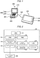
- FIG. 1 is a diagram illustrating appearances of a portable terminal device 100 which is a signature input device and a POS terminal device 200 which is a higher device to which the portable terminal device 100 is connected in an exemplary embodiment.
- the portable terminal device 100 and the POS terminal device 200 configure a signature input system.
- the POS terminal device (sales data registration device and settlement device) 200 receives an operation of a clerk who is an operator and performs registration processing (sales data registration processing) and settlement processing of a commodity purchased by a shopper.
- the POS terminal device 200 includes a display unit 210, an operation unit 220, a drawer 230 and the like.
- the display unit 210 is, for example, a liquid crystal display (LCD) and is stand on the back side of an upper side of a main body 201 and displays information toward the clerk.
- the operation unit 220 includes a keyboard 221 provided on the front side of the upper side of the main body 201, a touch panel 222 superposed on the surface of the display unit 210, a barcode scanner (not illustrated) and the like and receives various operations by these components from the clerk.
- the drawer 230 is positioned below the main body 201 and is a drawer-shaped lockable box and houses coins or paper money in a manner to be freely put and taken out.
- the POS terminal device 200 saves a price look-up (PLU) file received from a store controller in a non-volatile storage medium (not illustrated) such as a hard disk drive (HDD).
- a non-volatile storage medium such as a hard disk drive (HDD).
- HDD hard disk drive
- table format data and a commodity code and commodity information are stored to be associated with each other in the PLU file.
- One of commodity registration schemes is a scheme using a barcode scanner.
- a barcode corresponding to a commodity code is attached to most of commodities and the barcode scanner reads the barcode to thereby allow the POS terminal device 200 to read the commodity code.
- the POS terminal device 200 takes commodity information associated with the commodity code out of the PLU file and registers the commodity information as (one of) commodities on a settlement of one transaction.
- settlement processing is performed.
- the portable terminal device 100 is so-called tablet type terminal device and is a substantially rectangular plate shaped device.
- the portable terminal device 100 includes an LCD 110 having a screen 111 which occupies most of a surface of the exterior.
- the LCD 110 is an example of the display unit.
- a touch panel 120 is provided on the surface of the LCD 110.
- the touch panel 120 is a main portion of a function unit (operation unit) which is provided in the portable terminal device 100 and receives an operation.
- the touch panel 120 is an example of the input unit which receives an input by being in contact with a detection object.
- the detection object is, for example, a predetermined writing tool T (see FIG. 6 ) or the fingers.
- a detection method of the touch panel 120 may be a known detection method, for example, a pressure sensitive-type detection method and capacitance-type detection method.
- a pressure sensitive-type detection method any object capable of applying pressure may be used as a detection object.
- the capacitance-type detection method a substance having a predetermined conductivity (suitably pen-shaped or rod-shaped writing tool) or a portion of a human body may be used as a detection object.
- FIG. 2 is a block diagram illustrating a configuration of the portable terminal device 100.
- the portable terminal device 100 includes a display controller 112, a touch panel controller 121, a central processing unit (CPU) 131, a read only memory (ROM) 132, a random access memory (RAM) 133, a non-volatile memory 134, and a communication interface (I/F) 141, in addition to the configuration described above.
- the CPU 131, the ROM 132, and the RAM 133 configure the control unit 130.
- the display controller 112 drives and controls the LCD 110 based on screen data according to control of the control unit 130 and causes an image corresponding to the screen data to be displayed on the screen 111.
- the touch panel controller 121 transmits an output according to a position touched by the detection object to the control unit 130.
- the communication I/F 141 includes insertion ports of a cable 142 (see FIG. 1 ) connecting the portable terminal device 100 and the POS terminal device 200 and performs communications between the portable terminal device 100 and the POS terminal device 200.
- the ROM 132 stores various programs executed by the CPU 131.
- the RAM 133 is used as a work area where variable data is stored to be freely rewritten.
- the CPU 131 deploys the program stored in the ROM 132 onto the RAM 133 and executes various operation processing to thereby function as various modules and control respective units of the portable terminal device 100.
- the non-volatile memory 134 is a rewritable non-volatile memory storing various settings.
- FIG. 3 is a block diagram illustrating a functional configuration of the portable terminal device 100.
- the CPU 131, the ROM 132, and the RAM 133 configure the control unit 130.
- the control unit 130 integrally controls respects components of the portable terminal device 100.
- the control unit 130 has a guide display processing unit (guidance unit) 1301, a write processing unit (write unit) 1302, and an output processing unit (output unit) 1303.
- the portable terminal device 100 is used for inputting signature data requested by the POS terminal device 200 when a settlement (for example, credit settlement) which requires a signature by a person (that is, shopper) who pays the price is made.
- a settlement for example, credit settlement
- a person that is, shopper
- FIG. 4 is a front view of the portable terminal device 100 which indicates display contents of the LCD 110 before signing is performed.
- the control unit 130 causes the input field 113 indicating an area which receives a write of signature by the shopper to be displayed on the LCD 110.
- the control unit 130 causes a character string 114 indicating an amount to be displayed around the input field 113, for example, an upper side of the input field 113.
- the character string 114 is, for example, "Amount 10000 Yen".
- the guide display processing unit 1301 displays guide information 115 inside the input field 113.
- the guide information 115 is information which guides a signer (shopper) when writing a signature.
- the guide information 115 is a character string, for example, "Please sign here”.
- Information (for example, a place where signature is to be written) needed when signing is performed is notified to the signer by the guide information 115.
- the guide display processing unit 1301 causes the LCD 110 to display the guide information 115.
- the guide display processing unit 1301 causes the LCD 110 to display the guide information 115 by a color (for example, light color such as light blue or yellowish green) which is easy to be distinguished from a color (for example, black) of a line displaying a signature.
- a background color of the input field 113 may not be white, but may be a color of reduced brightness in order to clearly indicate the guide information 115 displayed by a light color. For example, when a color of the guide information 115 is light blue, a background color may be blue or the like.
- the write processing unit 1302 When the touch panel 120 receives an input into the input field 113, the write processing unit 1302 superposes the input on the guide information 115 based on an output from the touch panel 120 and displays, inside the input field 113, a locus of the detection object (a predetermined writing tool T or the like) brought into contact with the input field 113. The locus becomes a signature.
- the write processing unit 1302 causes the LCD 110 to display a signature by a line of a dark color such as black.
- the write processing unit 1302 erases the locus when the detection object brought into contact with the touch panel 120 moves from an inside of the input field 113 to an outside thereof. That is, when the locus which is being displayed while being updated is moved out of the input field 113, the write processing unit 1302 erases the locus. With this, a signature is not contained in (is moved out of) the input field 113, the signer is requested to rewrite a signature.
- the guide display processing unit 1301 causes attention information (not illustrated) to be displayed inside the input field 113.
- the attention information is contents of explanations for requesting signature rewriting and is, for example, "Please be informed that signature is moved out of a field and rewriting of signature is requested.”
- the output processing unit 1303 outputs data of an image containing the signature displayed inside the input field 113. More specifically, the output processing unit 1303 turns the signature obtained by excluding the guide information 115 from the display contents of the input field 113 into image data and transmits the image data to the POS terminal device 200 via the communication I/F 141.
- FIG. 5 is a flowchart indicating a flow of processing performed by the control unit 130 of the portable terminal device 100.
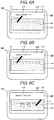
- FIGs. 6A to 6C are diagrams indicating transitions of the display contents of the LCD 110.
- the control unit 130 of the portable terminal device 100 waits for a signal requesting a signature input (No in Act S1).
- a signature request is received from the POS terminal device 200 which is conducting settlement processing of a credit settlement (Yes in Act S1)
- the control unit 130 causes the LCD 110 to display the input field 113 and guide information 115 (Act S2).
- control unit 130 waits for an input into the input field 113 (No in Act S3).
- an input into the input field 113 is performed as illustrated in FIG. 6B (Yes in Act S3)
- the control unit 130 displays a locus of the input on the input field 113 (Act S4).
- control unit 130 determines whether the signing is completed (Act S5).
- a completion of the signature is determined on the condition that an elapsed time from an interruption of an input by the detection object into the input field 113 exceeds a predetermined threshold value.
- the control unit 130 turns an image being displayed inside the input field 113 into image data (Act S6) and returns (transmits) the image data to the POS terminal device 200 which is a higher device (Act S7).
- Act S5 when it is determined that the signing is not completed (No in Act S5), the control unit 130 determines whether the locus is moved out of the input field 113 (Act S8). When it is determined that the locus is moved out of the field (Yes in Act S8), the control unit 130 erases the locus being displayed on the input field 113 and causes attention information to be displayed inside the input field 113 (Act S9).
- the guide information 115 is displayed inside the input field 113 and thus, it is possible for even an inexperienced signer (shopper) to make it difficult to overlook the guide information 115. Accordingly, the signature input device according to the present exemplary embodiment may have improved usability.
- a space for displaying guidance other than the input field as in the related art is not required and thus, it is possible to increase an occupation ratio of the input field 113 in the screen 111. That is, it is possible to largely display the input field 113. Accordingly, even if a signature is input using a tablet type terminal device of which surface slidability is better than paper and in which a size of handwritten characters is likely to become large, it is possible to write characters large, make characters difficult to move out of the field, and make it easy to write characters. Accordingly, rewriting of a signature is rarely performed and with this, the time and effort for the rewriting can be saved.
- the POS terminal device 200 is an example of a settlement device performing a settlement
- the present exemplary embodiment may also be applied to a signature input device connected to other settlement devices.
- an operation button for performing rewriting into the input field 113 may be provided on the screen 111 to make it possible to receive an operation of rewriting from the signer.
- a way of performing signing may be more specifically described by the guide information 115.
- conditions requesting as a signature such as "Please sign inside field.”, "Please sign with characters as large as possible.”, "Please don't move out of field” or the like may be listed.
- the guide display processing unit 1301 may erase the guide information 115 when an input into the input field 113 by the touch panel 120 is received. That is, the guide display processing unit 1301 may erase the guide information 115 with the start of displaying of the locus by the write processing unit 1302. As such, the guide information 115 is erased after writing of a signature and thus, it is possible to make the locus of writing easier to be viewed.
- attention information displayed inside the input field 113 by the guide display processing unit 1301 may be guide information ("Please sign here" or the like) which is the same as the guide information 115 displayed at first.
- FIG. 7 is a front view illustrating an example of screen display of the portable terminal device 300 in the present modification example.
- description of the same portion as that of the exemplary embodiment will be omitted and description of the portion different from the exemplary embodiment will be described.
- the same portion as that of the exemplary embodiment will be denoted by using the same reference numerals.
- the guide display processing unit 1301 instructs a size of characters suitable for a signature by the guide information 115. More specifically, the guide display processing unit 1301 displays a character string 116 inside the input field 113 as some of the guide information 115.
- the character string 116 is, for example, an "example of a character size" indicated by a font having a size preferable for a signature.
- a character size preferable for a signature is guided by the character string 116 such that it is possible to avoid that a signer writes a signature using extremely small characters.
- the character string 116 may also be symbols or figures.
- a program executed by the signature input device (portable terminal device 100) of the present exemplary embodiment is provided by being incorporated into the ROM 132 or the like.
- the program executed by the signature input device of the present exemplary embodiment may be configured to be provided, in a file having an installable format or an executable format, by being recorded in a computer readable recording medium such as a CD-ROM, a flexible disk (FD), a CD-R, a digital versatile disk (DVD).
- a computer readable recording medium such as a CD-ROM, a flexible disk (FD), a CD-R, a digital versatile disk (DVD).
- the program executed by the signature input device of the present exemplary embodiment is configured to be stored in a computer connected to a network such as the Internet and to be provided by being downloaded through a network. It is also preferable that the program executed by the signature input device of the present exemplary embodiment is provided or distributed through the network such as the Internet.
- the program executed by the signature input device of the present exemplary embodiment is configured by a module including the respective units described above (guide display processing unit (guidance unit) 1301, write processing unit (write unit) 1302, and output processing unit (output unit) 1303).
- the CPU reads the program from storage medium and executes the program to load the respective units described above onto a main memory device. With this, the guide display processing unit 1301, the write processing unit 1302, and the output processing unit 1303 are generated on the main memory device.
Landscapes
- Engineering & Computer Science (AREA)
- Physics & Mathematics (AREA)
- Theoretical Computer Science (AREA)
- General Physics & Mathematics (AREA)
- General Engineering & Computer Science (AREA)
- Human Computer Interaction (AREA)
- Multimedia (AREA)
- Nonlinear Science (AREA)
- Crystallography & Structural Chemistry (AREA)
- Chemical & Material Sciences (AREA)
- Optics & Photonics (AREA)
- Mathematical Physics (AREA)
- User Interface Of Digital Computer (AREA)
- Cash Registers Or Receiving Machines (AREA)
Abstract

Description
- The present invention relates to signature imputing technologies in general, and embodiments described herein relate in particular to a signature input device comprising several units, a signature input system including corresponding means and a method for inputting signature comprising the corresponding steps.
- In the related art, a signature input device is used by being connected to an electronic device such as a POS terminal device. The signature input device is, for example, a tablet type terminal device, creates image data of handwritten characters from a locus of touch input, and outputs the image data.
- In the signature input device of the related art, guide information, such as "Please sign here.", used when signing is performed is displayed on a side (upper side or lower side) other than an input field where a handwritten input is received.
- However, guide information displayed on a side other than the input field may not catch the signer's eye. This event remarkably appears, for example, when the signer is nervous about an unfamiliar electronic device.
- To solve such problems, there is provided a signature input device comprising:
- a display unit that includes a screen displaying an image and has an input field indicating an area at which a signature is written;
- a guide display processing unit that displays guide information when a signature is written inside the input field;
- an input unit that is provided on a surface of the display unit and receives an input by being in contact with a detection object;
- a write processing unit that displays, inside the input field, a locus of the detection object brought into contact with the input field; and
- an output processing unit that outputs data of an image displayed inside the input field.
- Preferably, when the input unit receives an input into the input field, the write processing unit displays the locus to be superposed on the guide information.
- Preferably still, the write processing unit erases the locus when the detection object brought into contact with the input unit moves from an inside of the input field to an outside of the input field.
- Preferably yet, the guide display processing unit instructs a size of characters for a signature according to the guide information.
- Preferably further, the guide display processing unit displays the guide information in light color, and the write processing unit displays the locus in a color darker than the guide information.
- The invention also relates to a system for inputting signature including:
- a display means that includes a screen displaying an image and has an input field indicating an area at which a signature is written;
- a guide display processing means that displays guide information when a signature is written inside the input field;
- an input means that is provided on a surface of the display means and receives an input by being in contact with a detection object;
- a write processing means that displays, inside the input field, a locus of the detection object brought into contact with the input field; and
- an output processing means that outputs data of an image displayed inside the input field.
- Suitably, when the input means receives an input into the input field, the write processing means displays the locus to be superposed on the guide information.
- Suitably still, the write processing means erases the locus when the detection object brought into contact with the input means moves from an inside of the input field to an outside of the input field.
- Suitably yet, the guide display processing means instructs a size of characters for a signature according to the guide information.
- Suitably further, the guide display processing means displays the guide information in light color, and
the write processing means displays the locus in a color darker than the guide information. - The invention further relates to a method for inputting signature, comprising the steps of:
- providing, in a display means, a screen displaying an image and an input field indicating an area at which a signature is written;
- displaying, by a guide display processing means, guide information when a signature is written inside the input field;
- providing an input means on a surface of the display means, the input means receiving an input by being in contact with a detection object;
- displaying, inside the input field, by a write processing means, a locus of the detection object brought into contact with the input field; and
- outputting, by an output processing means, data of an image displayed inside the input field.
- Typically, the displaying step by the write processing means comprises displaying the locus to be superposed on the guide information, when the input means receives an input into the input field.
- Typically still, the displaying step by the write processing means comprises erasing the locus when the detection object brought into contact with the input means moves from an inside of the input field to an outside of the input field.
- Typically yet, the displaying step by the guide display processing means comprises instructing a size of characters for a signature according to the guide information.
- Typically further, the displaying step by the guide display processing means comprises displaying the guide information in light color, and the displaying step by the write processing means comprises displaying the locus in a color darker than the guide information.
- The above and other objects, features and advantages of the present invention will be made apparent from the following description of the preferred embodiments, given as non-limiting examples, with reference to the accompanying drawings, in which:
-
FIG. 1 illustrates a diagram of appearances of a portable terminal device which is a signature input device and a POS terminal device which is a higher device to which the portable terminal device is connected in an exemplary embodiment. -
FIG. 2 illustrates a block diagram of a configuration of the portable terminal device. -
FIG. 3 illustrates a block diagram of a functional configuration of the portable terminal device. -
FIG. 4 illustrates a front view of the portable terminal device which indicates display contents of LCD before signing is performed. -
FIG. 5 illustrates a flowchart indicating a flow of processing performed by a control unit of the portable terminal device. -
FIGs. 6A to 6C illustrate diagrams indicating transitions of the display contents of the LCD. -
FIG. 7 illustrates a front view of an example of screen display of a portable terminal device in a modification example of the exemplary embodiment. - A problem to be solved by the present disclosure is to provide a signature input device which makes guidance available when signing is performed easy to catch the signer's eye even when the signer is nervous.
- A signature input device of an exemplary embodiment includes a display unit, a guide display processing unit, an input unit, a write processing unit, and an output processing unit. The display unit includes a screen displaying an image and has an input field indicating an area at which a signature is written. The guide display processing unit displays guide information when a signature is written inside the input field. The input unit is provided on a surface of the display unit and receives an input by being in contact with a detection object. The write processing unit displays, inside the input field, a locus of the detection object brought into contact with the input field. The output processing unit outputs data of an image displayed inside the input field.
- Though exemplary embodiments are presented mainly in the form of a device, they also apply mutatis mutandis to a system and a method, as defined in claims 6 to 10 and claims 11 to 15, respectively.
- An exemplary embodiment will be described with reference to drawings.
FIG. 1 is a diagram illustrating appearances of aportable terminal device 100 which is a signature input device and aPOS terminal device 200 which is a higher device to which theportable terminal device 100 is connected in an exemplary embodiment. Theportable terminal device 100 and thePOS terminal device 200 configure a signature input system. - The POS terminal device (sales data registration device and settlement device) 200 receives an operation of a clerk who is an operator and performs registration processing (sales data registration processing) and settlement processing of a commodity purchased by a shopper.
- The
POS terminal device 200 includes adisplay unit 210, anoperation unit 220, adrawer 230 and the like. Thedisplay unit 210 is, for example, a liquid crystal display (LCD) and is stand on the back side of an upper side of amain body 201 and displays information toward the clerk. Theoperation unit 220 includes a keyboard 221 provided on the front side of the upper side of themain body 201, a touch panel 222 superposed on the surface of thedisplay unit 210, a barcode scanner (not illustrated) and the like and receives various operations by these components from the clerk. Thedrawer 230 is positioned below themain body 201 and is a drawer-shaped lockable box and houses coins or paper money in a manner to be freely put and taken out. - The
POS terminal device 200 saves a price look-up (PLU) file received from a store controller in a non-volatile storage medium (not illustrated) such as a hard disk drive (HDD). For example, table format data and a commodity code and commodity information (commodity name, commodity price and the like) are stored to be associated with each other in the PLU file. - One of commodity registration schemes is a scheme using a barcode scanner. A barcode corresponding to a commodity code is attached to most of commodities and the barcode scanner reads the barcode to thereby allow the
POS terminal device 200 to read the commodity code. ThePOS terminal device 200 takes commodity information associated with the commodity code out of the PLU file and registers the commodity information as (one of) commodities on a settlement of one transaction. When thePOS terminal device 200 ends registration processing of the commodity purchased by a shopper, settlement processing is performed. - The portable
terminal device 100 is so-called tablet type terminal device and is a substantially rectangular plate shaped device. The portableterminal device 100 includes anLCD 110 having ascreen 111 which occupies most of a surface of the exterior. TheLCD 110 is an example of the display unit. - A
touch panel 120 is provided on the surface of theLCD 110. Thetouch panel 120 is a main portion of a function unit (operation unit) which is provided in the portableterminal device 100 and receives an operation. Thetouch panel 120 is an example of the input unit which receives an input by being in contact with a detection object. The detection object is, for example, a predetermined writing tool T (seeFIG. 6 ) or the fingers. - A detection method of the
touch panel 120 may be a known detection method, for example, a pressure sensitive-type detection method and capacitance-type detection method. According to the pressure sensitive-type detection method, any object capable of applying pressure may be used as a detection object. According to the capacitance-type detection method, a substance having a predetermined conductivity (suitably pen-shaped or rod-shaped writing tool) or a portion of a human body may be used as a detection object. -
FIG. 2 is a block diagram illustrating a configuration of the portableterminal device 100. The portableterminal device 100 includes adisplay controller 112, atouch panel controller 121, a central processing unit (CPU) 131, a read only memory (ROM) 132, a random access memory (RAM) 133, anon-volatile memory 134, and a communication interface (I/F) 141, in addition to the configuration described above. TheCPU 131, theROM 132, and theRAM 133 configure thecontrol unit 130. - The
display controller 112 drives and controls theLCD 110 based on screen data according to control of thecontrol unit 130 and causes an image corresponding to the screen data to be displayed on thescreen 111. Thetouch panel controller 121 transmits an output according to a position touched by the detection object to thecontrol unit 130. The communication I/F 141 includes insertion ports of a cable 142 (seeFIG. 1 ) connecting the portableterminal device 100 and thePOS terminal device 200 and performs communications between the portableterminal device 100 and thePOS terminal device 200. - The
ROM 132 stores various programs executed by theCPU 131. TheRAM 133 is used as a work area where variable data is stored to be freely rewritten. TheCPU 131 deploys the program stored in theROM 132 onto theRAM 133 and executes various operation processing to thereby function as various modules and control respective units of the portableterminal device 100. Thenon-volatile memory 134 is a rewritable non-volatile memory storing various settings. -
FIG. 3 is a block diagram illustrating a functional configuration of the portableterminal device 100. TheCPU 131, theROM 132, and theRAM 133 configure thecontrol unit 130. Thecontrol unit 130 integrally controls respects components of the portableterminal device 100. Thecontrol unit 130 has a guide display processing unit (guidance unit) 1301, a write processing unit (write unit) 1302, and an output processing unit (output unit) 1303. - Here, the portable
terminal device 100 is used for inputting signature data requested by thePOS terminal device 200 when a settlement (for example, credit settlement) which requires a signature by a person (that is, shopper) who pays the price is made. -
FIG. 4 is a front view of the portableterminal device 100 which indicates display contents of theLCD 110 before signing is performed. Thecontrol unit 130 causes theinput field 113 indicating an area which receives a write of signature by the shopper to be displayed on theLCD 110. Thecontrol unit 130 causes acharacter string 114 indicating an amount to be displayed around theinput field 113, for example, an upper side of theinput field 113. Thecharacter string 114 is, for example, "Amount 10000 Yen". - The guide
display processing unit 1301 displays guideinformation 115 inside theinput field 113. Theguide information 115 is information which guides a signer (shopper) when writing a signature. Theguide information 115 is a character string, for example, "Please sign here". Information (for example, a place where signature is to be written) needed when signing is performed is notified to the signer by theguide information 115. - When a signature input is requested from the
POS terminal device 200, the guidedisplay processing unit 1301 causes theLCD 110 to display theguide information 115. - Here, the guide
display processing unit 1301 causes theLCD 110 to display theguide information 115 by a color (for example, light color such as light blue or yellowish green) which is easy to be distinguished from a color (for example, black) of a line displaying a signature. A background color of theinput field 113 may not be white, but may be a color of reduced brightness in order to clearly indicate theguide information 115 displayed by a light color. For example, when a color of theguide information 115 is light blue, a background color may be blue or the like. - A shopper who is a signer signs a signature inside the
input field 113 using a writing tool T or the like handed from a clerk. That is, the shopper moves the tip of the writing tool T by putting the writing tool T to a position of thetouch panel 120 at which theinput field 113 is displayed. - When the
touch panel 120 receives an input into theinput field 113, thewrite processing unit 1302 superposes the input on theguide information 115 based on an output from thetouch panel 120 and displays, inside theinput field 113, a locus of the detection object (a predetermined writing tool T or the like) brought into contact with theinput field 113. The locus becomes a signature. Thewrite processing unit 1302 causes theLCD 110 to display a signature by a line of a dark color such as black. - The
write processing unit 1302 erases the locus when the detection object brought into contact with thetouch panel 120 moves from an inside of theinput field 113 to an outside thereof. That is, when the locus which is being displayed while being updated is moved out of theinput field 113, thewrite processing unit 1302 erases the locus. With this, a signature is not contained in (is moved out of) theinput field 113, the signer is requested to rewrite a signature. - When the
write processing unit 1302 erases the locus, the guidedisplay processing unit 1301 causes attention information (not illustrated) to be displayed inside theinput field 113. In this case, the attention information is contents of explanations for requesting signature rewriting and is, for example, "Please be informed that signature is moved out of a field and rewriting of signature is requested." - The
output processing unit 1303 outputs data of an image containing the signature displayed inside theinput field 113. More specifically, theoutput processing unit 1303 turns the signature obtained by excluding theguide information 115 from the display contents of theinput field 113 into image data and transmits the image data to thePOS terminal device 200 via the communication I/F 141. - In such configuration, processing performed by the portable
terminal device 100 and thePOS terminal device 200 will be described in the following.FIG. 5 is a flowchart indicating a flow of processing performed by thecontrol unit 130 of the portableterminal device 100.FIGs. 6A to 6C are diagrams indicating transitions of the display contents of theLCD 110. - The
control unit 130 of the portableterminal device 100 waits for a signal requesting a signature input (No in Act S1). When a signature request is received from thePOS terminal device 200 which is conducting settlement processing of a credit settlement (Yes in Act S1), thecontrol unit 130, as illustrated inFIG. 6A , causes theLCD 110 to display theinput field 113 and guide information 115 (Act S2). - Subsequently, the
control unit 130 waits for an input into the input field 113 (No in Act S3). When an input into theinput field 113 is performed as illustrated inFIG. 6B (Yes in Act S3), thecontrol unit 130, as illustrated inFIG. 6C , displays a locus of the input on the input field 113 (Act S4). - Next, the
control unit 130 determines whether the signing is completed (Act S5). A completion of the signature is determined on the condition that an elapsed time from an interruption of an input by the detection object into theinput field 113 exceeds a predetermined threshold value. - When it is determined that the signing is completed (Yes in Act S5), the
control unit 130 turns an image being displayed inside theinput field 113 into image data (Act S6) and returns (transmits) the image data to thePOS terminal device 200 which is a higher device (Act S7). - In Act S5, when it is determined that the signing is not completed (No in Act S5), the
control unit 130 determines whether the locus is moved out of the input field 113 (Act S8). When it is determined that the locus is moved out of the field (Yes in Act S8), thecontrol unit 130 erases the locus being displayed on theinput field 113 and causes attention information to be displayed inside the input field 113 (Act S9). - In Act S8, when it is determined that the locus is not moved out of the field (No in Act S8), the
control unit 130 returns processing to Act S5. - As such, according to the present exemplary embodiment, the
guide information 115 is displayed inside theinput field 113 and thus, it is possible for even an inexperienced signer (shopper) to make it difficult to overlook theguide information 115. Accordingly, the signature input device according to the present exemplary embodiment may have improved usability. - According to the present exemplary embodiment, a space for displaying guidance other than the input field as in the related art is not required and thus, it is possible to increase an occupation ratio of the
input field 113 in thescreen 111. That is, it is possible to largely display theinput field 113. Accordingly, even if a signature is input using a tablet type terminal device of which surface slidability is better than paper and in which a size of handwritten characters is likely to become large, it is possible to write characters large, make characters difficult to move out of the field, and make it easy to write characters. Accordingly, rewriting of a signature is rarely performed and with this, the time and effort for the rewriting can be saved. - In the present exemplary embodiment, although the
POS terminal device 200 is an example of a settlement device performing a settlement, when the present exemplary embodiment is embodied, the present exemplary embodiment may also be applied to a signature input device connected to other settlement devices. - When the present exemplary embodiment is embodied, an operation button for performing rewriting into the
input field 113 may be provided on thescreen 111 to make it possible to receive an operation of rewriting from the signer. - Furthermore, when the present exemplary embodiment is embodied, a way of performing signing may be more specifically described by the
guide information 115. For example, conditions requesting as a signature such as "Please sign inside field.", "Please sign with characters as large as possible.", "Please don't move out of field" or the like may be listed. - When the present exemplary embodiment is embodied, the guide
display processing unit 1301 may erase theguide information 115 when an input into theinput field 113 by thetouch panel 120 is received. That is, the guidedisplay processing unit 1301 may erase theguide information 115 with the start of displaying of the locus by thewrite processing unit 1302. As such, theguide information 115 is erased after writing of a signature and thus, it is possible to make the locus of writing easier to be viewed. - After a locus of writing is erased due to moving out of the field, attention information displayed inside the
input field 113 by the guidedisplay processing unit 1301 may be guide information ("Please sign here" or the like) which is the same as theguide information 115 displayed at first. - A modification example of the exemplary embodiment will be described with reference to drawings.
FIG. 7 is a front view illustrating an example of screen display of the portableterminal device 300 in the present modification example. In the present modification example, description of the same portion as that of the exemplary embodiment will be omitted and description of the portion different from the exemplary embodiment will be described. In the present modification example, the same portion as that of the exemplary embodiment will be denoted by using the same reference numerals. - In the present modification example, the guide
display processing unit 1301 instructs a size of characters suitable for a signature by theguide information 115. More specifically, the guidedisplay processing unit 1301 displays acharacter string 116 inside theinput field 113 as some of theguide information 115. Thecharacter string 116 is, for example, an "example of a character size" indicated by a font having a size preferable for a signature. - As in the present modification example, a character size preferable for a signature is guided by the
character string 116 such that it is possible to avoid that a signer writes a signature using extremely small characters. - The
character string 116 may also be symbols or figures. - As described above, a program executed by the signature input device (portable terminal device 100) of the present exemplary embodiment is provided by being incorporated into the
ROM 132 or the like. - The program executed by the signature input device of the present exemplary embodiment may be configured to be provided, in a file having an installable format or an executable format, by being recorded in a computer readable recording medium such as a CD-ROM, a flexible disk (FD), a CD-R, a digital versatile disk (DVD).
- Furthermore, it is also preferable that the program executed by the signature input device of the present exemplary embodiment is configured to be stored in a computer connected to a network such as the Internet and to be provided by being downloaded through a network. It is also preferable that the program executed by the signature input device of the present exemplary embodiment is provided or distributed through the network such as the Internet.
- The program executed by the signature input device of the present exemplary embodiment is configured by a module including the respective units described above (guide display processing unit (guidance unit) 1301, write processing unit (write unit) 1302, and output processing unit (output unit) 1303). The CPU (processor) reads the program from storage medium and executes the program to load the respective units described above onto a main memory device. With this, the guide
display processing unit 1301, thewrite processing unit 1302, and theoutput processing unit 1303 are generated on the main memory device. - While certain embodiments have been described, these embodiments have been presented by way of example only, and are not intended to limit the scope of invention. Indeed, the novel embodiments described herein may be embodied in a variety of other forms; furthermore, various omissions, substitutions and changes in the form of the embodiments described herein may be made without departing from the framework of the inventions. The accompanying claims and their equivalents are intended to cover such forms or modifications as would fall within the scope and framework of the inventions.
- [PTL 1]
JP-A-2015-207100
Claims (15)
- A signature input device comprising:a display unit that includes a screen displaying an image and has an input field indicating an area at which a signature is written;a guide display processing unit that displays guide information when a signature is written inside the input field;an input unit that is provided on a surface of the display unit and receives an input by being in contact with a detection object;a write processing unit that displays, inside the input field, a locus of the detection object brought into contact with the input field; andan output processing unit that outputs data of an image displayed inside the input field.
- The device according to claim 1,
wherein when the input unit receives an input into the input field, the write processing unit displays the locus to be superposed on the guide information. - The device according to claim 1 or 2,
wherein the write processing unit erases the locus when the detection object brought into contact with the input unit moves from an inside of the input field to an outside of the input field. - The device according to any one of claims 1 to 3,
wherein the guide display processing unit instructs a size of characters for a signature according to the guide information. - The device according to any one of claims 1 to 4,
wherein the guide display processing unit displays the guide information in light color, and
the write processing unit displays the locus in a color darker than the guide information. - A system for inputting signature including:a display means that includes a screen displaying an image and has an input field indicating an area at which a signature is written;a guide display processing means that displays guide information when a signature is written inside the input field;an input means that is provided on a surface of the display means and receives an input by being in contact with a detection object;a write processing means that displays, inside the input field, a locus of the detection object brought into contact with the input field; andan output processing means that outputs data of an image displayed inside the input field.
- The system according to claim 6,
wherein when the input means receives an input into the input field, the write processing means displays the locus to be superposed on the guide information. - The system according to claim 6 or 7,
wherein the write processing means erases the locus when the detection object brought into contact with the input means moves from an inside of the input field to an outside of the input field. - The system according to any one of claims 6 to 8,
wherein the guide display processing means instructs a size of characters for a signature according to the guide information. - The system according to any one of claims 6 to 9,
wherein the guide display processing means displays the guide information in light color, and
the write processing means displays the locus in a color darker than the guide information. - A method for inputting signature, comprising the steps of:- providing, in a display means, a screen displaying an image and an input field indicating an area at which a signature is written;- displaying, by a guide display processing means, guide information when a signature is written inside the input field;- providing an input means on a surface of the display means, the input means receiving an input by being in contact with a detection object;- displaying, inside the input field, by a write processing means, a locus of the detection object brought into contact with the input field; and- outputting, by an output processing means, data of an image displayed inside the input field.
- The method according to claim 11,
wherein the displaying step by the write processing means comprises displaying the locus to be superposed on the guide information, when the input means receives an input into the input field. - The method according to claim 11 or 12,
wherein the displaying step by the write processing means comprises erasing the locus when the detection object brought into contact with the input means moves from an inside of the input field to an outside of the input field. - The method according to any one of claims 11 to 13,
wherein the displaying step by the guide display processing means comprises instructing a size of characters for a signature according to the guide information. - The method according to any one of claims 11 to 14,
wherein the displaying step by the guide display processing means comprises displaying the guide information in light color, and
the displaying step by the write processing means comprises displaying the locus in a color darker than the guide information.
Applications Claiming Priority (1)
| Application Number | Priority Date | Filing Date | Title |
|---|---|---|---|
| JP2016035755A JP6764662B2 (en) | 2016-02-26 | 2016-02-26 | Signature input device |
Publications (1)
| Publication Number | Publication Date |
|---|---|
| EP3211517A1 true EP3211517A1 (en) | 2017-08-30 |
Family
ID=58098511
Family Applications (1)
| Application Number | Title | Priority Date | Filing Date |
|---|---|---|---|
| EP17156891.8A Withdrawn EP3211517A1 (en) | 2016-02-26 | 2017-02-20 | Signature input device |
Country Status (4)
| Country | Link |
|---|---|
| US (1) | US20170249038A1 (en) |
| EP (1) | EP3211517A1 (en) |
| JP (1) | JP6764662B2 (en) |
| CN (1) | CN107132960A (en) |
Families Citing this family (2)
| Publication number | Priority date | Publication date | Assignee | Title |
|---|---|---|---|---|
| JP7280682B2 (en) * | 2018-10-24 | 2023-05-24 | 東芝テック株式会社 | Signature input device, payment terminal, program, signature input method |
| CN115657345A (en) * | 2022-10-25 | 2023-01-31 | 深圳市点亮视界科技有限公司 | Display module detection method of electronic terminal and related equipment |
Citations (3)
| Publication number | Priority date | Publication date | Assignee | Title |
|---|---|---|---|---|
| JP2003058890A (en) * | 2001-08-20 | 2003-02-28 | Hitachi Ltd | Signature verification system, method and recording medium |
| US20150148106A1 (en) * | 2013-11-22 | 2015-05-28 | Lg Electronics Inc. | Mobile terminal and method for controlling the same |
| JP2015207100A (en) | 2014-04-18 | 2015-11-19 | 東芝テック株式会社 | Information processing device and program |
Family Cites Families (13)
| Publication number | Priority date | Publication date | Assignee | Title |
|---|---|---|---|---|
| JPH05197477A (en) * | 1992-01-20 | 1993-08-06 | Mitsubishi Electric Corp | Handwriting information input device |
| JP2009171418A (en) * | 2008-01-18 | 2009-07-30 | Sharp Corp | Image processing apparatus and image processing method |
| US20110309142A1 (en) * | 2010-06-17 | 2011-12-22 | Ncr Corporation | Payment card reader apparatus and method of operating a payment card reader apparatus |
| JP2012068759A (en) * | 2010-09-21 | 2012-04-05 | Brother Ind Ltd | Display device and display control program |
| CN102053755A (en) * | 2011-01-21 | 2011-05-11 | 北京点聚信息技术有限公司 | Dynamic signature hand writing technology |
| CN102156616B (en) * | 2011-04-19 | 2013-01-23 | 唐光智 | Touch screen key-writing input method |
| CN102364426A (en) * | 2011-07-29 | 2012-02-29 | 广东小天才科技有限公司 | Drawing and writing method with self-learning function |
| DE102011117214B4 (en) * | 2011-10-28 | 2016-06-16 | Stepover Gmbh | A method for detecting an unauthorized opening of a signature device, signature device and computer system with the same |
| CN202634543U (en) * | 2011-11-22 | 2012-12-26 | 北京华旗随身数码股份有限公司 | Digital image capturing device with additional signature on image |
| JP5849778B2 (en) * | 2012-03-02 | 2016-02-03 | カシオ計算機株式会社 | Handwriting input device and program |
| JP6278641B2 (en) * | 2013-08-30 | 2018-02-14 | 株式会社ベネッセコーポレーション | Writing practice system and program |
| EP2884470A1 (en) * | 2013-12-11 | 2015-06-17 | Panasonic Intellectual Property Management Co., Ltd. | Mobile payment terminal device |
| JP5830693B2 (en) * | 2013-12-11 | 2015-12-09 | パナソニックIpマネジメント株式会社 | Payment terminal device |
-
2016
- 2016-02-26 JP JP2016035755A patent/JP6764662B2/en active Active
-
2017
- 2017-02-17 CN CN201710087462.5A patent/CN107132960A/en active Pending
- 2017-02-17 US US15/435,695 patent/US20170249038A1/en not_active Abandoned
- 2017-02-20 EP EP17156891.8A patent/EP3211517A1/en not_active Withdrawn
Patent Citations (3)
| Publication number | Priority date | Publication date | Assignee | Title |
|---|---|---|---|---|
| JP2003058890A (en) * | 2001-08-20 | 2003-02-28 | Hitachi Ltd | Signature verification system, method and recording medium |
| US20150148106A1 (en) * | 2013-11-22 | 2015-05-28 | Lg Electronics Inc. | Mobile terminal and method for controlling the same |
| JP2015207100A (en) | 2014-04-18 | 2015-11-19 | 東芝テック株式会社 | Information processing device and program |
Non-Patent Citations (6)
| Title |
|---|
| ANONYMOUS: "History for README.md - willowsystems/jSignature . GitHub", 10 October 2012 (2012-10-10), XP055609200, Retrieved from the Internet <URL:https://github.com/willowsystems/jSignature/commits/master/README.md> [retrieved on 20190726] * |
| ANONYMOUS: "jSignature - About - Page Info", 2 November 2012 (2012-11-02), XP055383008, Retrieved from the Internet <URL:https://willowsystems.github.io/jSignature/#/about/> [retrieved on 20170620] * |
| ANONYMOUS: "jSignature - About", 2 November 2012 (2012-11-02), XP055382990, Retrieved from the Internet <URL:https://willowsystems.github.io/jSignature/#/about/> [retrieved on 20170620] * |
| ANONYMOUS: "jSignature - Demo - Page Info", 2 November 2012 (2012-11-02), XP055383035, Retrieved from the Internet <URL:https://willowsystems.github.io/jSignature/#/demo/> [retrieved on 20170620] * |
| ANONYMOUS: "jSignature - Demo", 2 November 2012 (2012-11-02), XP055383081, Retrieved from the Internet <URL:https://willowsystems.github.io/jSignature/#/demo/> [retrieved on 20170620] * |
| ANONYMOUS: "jSignature/README.md at master . willowsystems/jSignature . GitHub", 10 October 2012 (2012-10-10), XP055609198, Retrieved from the Internet <URL:https://github.com/willowsystems/jSignature/blob/master/README.md> [retrieved on 20190726] * |
Also Published As
| Publication number | Publication date |
|---|---|
| CN107132960A (en) | 2017-09-05 |
| US20170249038A1 (en) | 2017-08-31 |
| JP2017151880A (en) | 2017-08-31 |
| JP6764662B2 (en) | 2020-10-07 |
Similar Documents
| Publication | Publication Date | Title |
|---|---|---|
| US9928496B2 (en) | Generating a temporal physical payment card | |
| JP2011123906A5 (en) | ||
| US20170186010A1 (en) | Register system configured to automatically generate notifications regarding product registrations | |
| US8872845B2 (en) | Information display apparatus and computer-readable storage medium | |
| EP3185200A1 (en) | Point-of-sale terminal including a touch panel screen having expanded areas for selecting objects when the objects are partially obscured | |
| US20170249038A1 (en) | Signature input device | |
| KR102174567B1 (en) | Electric device and method for displaying payment screen of multiple payment items | |
| CN110097057B (en) | Image processing device and storage medium | |
| US20170091737A1 (en) | Checkout system and method | |
| US20200143351A1 (en) | Pos terminal device and pos system | |
| EP3644175B1 (en) | Signature input device, settlement terminal, and signature input method | |
| CN118277012A (en) | Interface display method, device, electronic device and storage medium | |
| CN110120136B (en) | Input terminal, control method, non-transitory computer-readable storage medium, and device | |
| US10909517B2 (en) | Registration settlement apparatus and information processing method for controlling the same | |
| JP2017004134A (en) | Information processing apparatus, information processing method, and program | |
| US10904609B2 (en) | Display control device and display control method | |
| JP6857055B2 (en) | Payment terminal equipment and programs | |
| JP2001256555A (en) | Product sales registration processor | |
| US20210256494A1 (en) | Payment terminal and control method for a payment terminal | |
| JP2015228109A (en) | Settlement device and program | |
| JP6490022B2 (en) | POS terminal device, POS terminal setting method, and POS terminal setting program | |
| JP6872937B2 (en) | Payment terminal equipment and programs | |
| CN114594895A (en) | Information interaction confirmation method, device, device and storage medium | |
| KR100564017B1 (en) | Financial automated equipment with separate advertising display | |
| JP6505374B2 (en) | Display device, display method, program and recording medium |
Legal Events
| Date | Code | Title | Description |
|---|---|---|---|
| PUAI | Public reference made under article 153(3) epc to a published international application that has entered the european phase |
Free format text: ORIGINAL CODE: 0009012 |
|
| STAA | Information on the status of an ep patent application or granted ep patent |
Free format text: STATUS: THE APPLICATION HAS BEEN PUBLISHED |
|
| AK | Designated contracting states |
Kind code of ref document: A1 Designated state(s): AL AT BE BG CH CY CZ DE DK EE ES FI FR GB GR HR HU IE IS IT LI LT LU LV MC MK MT NL NO PL PT RO RS SE SI SK SM TR |
|
| AX | Request for extension of the european patent |
Extension state: BA ME |
|
| STAA | Information on the status of an ep patent application or granted ep patent |
Free format text: STATUS: REQUEST FOR EXAMINATION WAS MADE |
|
| 17P | Request for examination filed |
Effective date: 20180228 |
|
| RBV | Designated contracting states (corrected) |
Designated state(s): AL AT BE BG CH CY CZ DE DK EE ES FI FR GB GR HR HU IE IS IT LI LT LU LV MC MK MT NL NO PL PT RO RS SE SI SK SM TR |
|
| STAA | Information on the status of an ep patent application or granted ep patent |
Free format text: STATUS: EXAMINATION IS IN PROGRESS |
|
| 17Q | First examination report despatched |
Effective date: 20190807 |
|
| STAA | Information on the status of an ep patent application or granted ep patent |
Free format text: STATUS: THE APPLICATION HAS BEEN WITHDRAWN |
|
| 18W | Application withdrawn |
Effective date: 20191212 |