EP3211495A1 - Programmable logic controller, control method thereof and control program thereof - Google Patents
Programmable logic controller, control method thereof and control program thereof Download PDFInfo
- Publication number
- EP3211495A1 EP3211495A1 EP16203706.3A EP16203706A EP3211495A1 EP 3211495 A1 EP3211495 A1 EP 3211495A1 EP 16203706 A EP16203706 A EP 16203706A EP 3211495 A1 EP3211495 A1 EP 3211495A1
- Authority
- EP
- European Patent Office
- Prior art keywords
- command
- programmable logic
- logic controller
- interface device
- communication interface
- Prior art date
- Legal status (The legal status is an assumption and is not a legal conclusion. Google has not performed a legal analysis and makes no representation as to the accuracy of the status listed.)
- Granted
Links
Images




Classifications
-
- G—PHYSICS
- G05—CONTROLLING; REGULATING
- G05B—CONTROL OR REGULATING SYSTEMS IN GENERAL; FUNCTIONAL ELEMENTS OF SUCH SYSTEMS; MONITORING OR TESTING ARRANGEMENTS FOR SUCH SYSTEMS OR ELEMENTS
- G05B19/00—Program-control systems
- G05B19/02—Program-control systems electric
- G05B19/04—Program control other than numerical control, i.e. in sequence controllers or logic controllers
- G05B19/05—Programmable logic controllers, e.g. simulating logic interconnections of signals according to ladder diagrams or function charts
- G05B19/056—Programming the PLC
-
- G—PHYSICS
- G05—CONTROLLING; REGULATING
- G05B—CONTROL OR REGULATING SYSTEMS IN GENERAL; FUNCTIONAL ELEMENTS OF SUCH SYSTEMS; MONITORING OR TESTING ARRANGEMENTS FOR SUCH SYSTEMS OR ELEMENTS
- G05B19/00—Program-control systems
- G05B19/02—Program-control systems electric
- G05B19/04—Program control other than numerical control, i.e. in sequence controllers or logic controllers
- G05B19/05—Programmable logic controllers, e.g. simulating logic interconnections of signals according to ladder diagrams or function charts
- G05B19/054—Input/output
-
- G—PHYSICS
- G05—CONTROLLING; REGULATING
- G05B—CONTROL OR REGULATING SYSTEMS IN GENERAL; FUNCTIONAL ELEMENTS OF SUCH SYSTEMS; MONITORING OR TESTING ARRANGEMENTS FOR SUCH SYSTEMS OR ELEMENTS
- G05B2219/00—Program-control systems
- G05B2219/10—Plc systems
- G05B2219/13—Plc programming
- G05B2219/13004—Programming the plc
-
- G—PHYSICS
- G05—CONTROLLING; REGULATING
- G05B—CONTROL OR REGULATING SYSTEMS IN GENERAL; FUNCTIONAL ELEMENTS OF SUCH SYSTEMS; MONITORING OR TESTING ARRANGEMENTS FOR SUCH SYSTEMS OR ELEMENTS
- G05B2219/00—Program-control systems
- G05B2219/10—Plc systems
- G05B2219/13—Plc programming
- G05B2219/13149—Encapsulated actuator model with standardized interface: state, action, interlock
-
- G—PHYSICS
- G05—CONTROLLING; REGULATING
- G05B—CONTROL OR REGULATING SYSTEMS IN GENERAL; FUNCTIONAL ELEMENTS OF SUCH SYSTEMS; MONITORING OR TESTING ARRANGEMENTS FOR SUCH SYSTEMS OR ELEMENTS
- G05B2219/00—Program-control systems
- G05B2219/10—Plc systems
- G05B2219/15—Plc structure of the system
- G05B2219/15013—Set configuration, address of connected module from fixed non volatile
Definitions
- the invention relates to a programmable logic controller.
- a programmable logic controller is connected to external equipment through a communication interface device.
- the external equipment for example, a bar code reader
- the PLC transceives data through the specific port.
- the PLC sends a command to the communication interface device to send data to the external equipment through the specific port, or sends a command to the communication interface device to receive data from the external equipment through the specific port. These commands are recorded in a user program of the PLC.
- the communication interface device is sometimes directly installed on a connector of the PLC or sometimes installed on a coupler (slave) on a field network taking the PLC as a master, and when a user records the aforementioned commands in the user program, a connection position of the communication interface device (i.e. whether the communication interface device is directly installed on the connector of the PLC or installed on the coupler on the field network) has to be recognized for recording the commands.
- Patent literature 1 Japan Patent publication No. 9-44212 (published on February 14, 1997 )
- the prior art has following problems: the command has to be rewritten according to the connection position (address) of the communication interface device, and if the connection position of the communication interface deice is changed, a user program has to be accordingly changed.
- the invention reduces the time required for changing the user program along with the change of the connection position of the communication interface device.
- the invention provides a programmable logic controller, which is connected to external equipment through a communication interface device, and the programmable logic controller includes a memory, containing a user program and a setting document, where the user program records both of a command for the communication interface device and command target information thereof, and the setting document saves address information corresponding to the command target information; and a processor, reading the user program and the setting document to execute the command for the communication interface device.
- the command and the command target information thereof are recorded in the user program, and the address information corresponding to the command target information is separately saved in the setting document. Therefore, in case that the connection position (address) of the communication interface device is changed, the setting document can be changed without changing the user program or changing of the user program can be set to the minimum.
- the command target information includes a type, an identity and a port number of the communication interface device.
- the processor executes the command based on the command target information, the address information and structure information of a system connected to the programmable logic controller and the communication interface device.
- the command target information is an input variation of a function block of the command.
- the communication interface device is a serial communication unit installed on a coupler unit, or on a connector of the programmable logic controller, where the coupler unit is connected to the programmable logic controller through a field network.
- the communication interface device is an option board (communication board) installed in a slot of the programmable logic controller.
- the memory stores a structure document recording the structure information of the system.
- the invention provides a control method of a programmable logic controller, where the programmable logic controller is connected to external equipment through a communication interface device, and the control method of the programmable logic controller includes a step of reading a user program and a setting document, where the user program records both of a command for the communication interface device and command target information thereof, and the setting document saves address information corresponding to the command target information; and a step of processing the command for the communication interface device.
- the invention provides a control program of a programmable logic controller, where the programmable logic controller is connected to external equipment through a communication interface device, and a processor of the programmable logic control executes following steps according to the control program of the programmable logic controller: a step of reading a user program and a setting document, where the user program records both of a command for the communication interface device and command target information thereof, and the setting document saves address information corresponding to the command target information; and a step of processing the command for the communication interface device.
- the programmable logic controller of the invention reduces the time required for changing the user program taken place along with the change of the connection position of the communication interface device.
- a programmable logic controller (referred to as PLC hereinafter) 10 of the present embodiment is connected to a coupler unit 20 through a field network 15, and a serial communication unit 30 is connected to the coupler unit 20, and the serial communication unit 30 is connected to external equipment 40 through a serial line 35.
- the PLC 10 can be connected to a support tool 50.
- the field network 15 is an Ethernet control automation technology (Ethernet CAT: trademark) network
- the PLC 10 is an Ethernet CAT master
- the coupler unit 20 is an interface used for implementing process data communication (process data objects (PDO) communication) between the PLC 10 and the serial communication unit 30 on the Ethernet CAT network.
- PDO process data objects
- the PLC 10 serving as the master manages the field network 15, and monitors states of slaves (the coupler unit 20 and the serial communication unit 30), or performs PDO communication with the slaves.
- the serial communication unit 30 performs the PDO communication with the PLC 10 through the coupler unit 20, and performs serial communication with the external equipment 40 (serial communication equipment) through the serial line 35.
- the support tool 50 connected to the PLC 10 is a terminal (computer, etc.) running support software, and the user uses the support software to set the field network 15 and the slaves, or produce a user program sent to the PLC 10, or produce a setting document, etc.
- the PLC 10 has a memory 7 and a processor 8, the memory 7 saves a user program 11 sent by the support tool 50 and a system program 12.
- a communication command for example, a sending command or a receiving command
- the external equipment 40 is recorded.
- a specific communication sequence corresponding to the communication command is recorded, and the processor 8 reads the communication command from the user program 11 to execute the communication sequence recorded in the system program 12.
- the PLC 10 performs the PDO communication with the slaves (the coupler unit 20 and the serial communication unit 30) through the field network 15.
- the sending data coming from the PLC 10 is sequentially transferred to a buffer of the serial communication unit 30 through the field network 15 during each process data communication period, and is then sent to the serial line 35.
- the PLC 10 receives data, as shown in FIG. 3b , the receiving data coming from the serial line 35 is saved to the buffer of the serial communication unit 30, and is then transferred to the PLC 10 through the field network 15 during each process data communication period.
- FIG. 4 and FIG. 5 are flowcharts illustrating an example of a sending sequence (sending of a character string A-Z).
- step S2 the serial communication unit 30 receives the output notification data 1.
- step S4 the PLC 10 receives the input notification data 1, and learns that the serial communication unit 30 normally receives the character string A-Z according to the value of the output SID response.
- step S5 the serial communication unit 30 saves the character string A-Z to the buffer of itself (referring to FIG. 3a ).
- step S7 the serial communication unit 30 receives the output notification data 2.
- step S9 the PLC 10 receives the input notification data 2, and learns that the serial communication unit 30 normally receives the character string U-Z according to the value of the output SID response.
- the PLC 10 (the processor 8 of the PLC 10) reads the sending command of the user program 11, the PLC 10 executes the sending sequence (S1, S4, S6, S9, S11, S13) recorded in the system program 12.
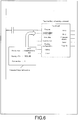
- the sending command of the user program 11 is as that shown in FIG. 6 , and can be recorded by using a function block, and can be inserted in a ladder circuit diagram.
- an input variable of a device port is prepared, and the command target information is input to the input variable.
- the command target information refers to a device type of a command target, an identity (ID) of the command target and an object port number (a port communicating with the PLC 10 and connected to the external equipment) of the command target.
- ID an identity of the command target
- object port number a port communicating with the PLC 10 and connected to the external equipment
- the processor 8 of the PLC 10 constructs a communication path of the serial communication unit 30 in the coupler unit 20 installed on the field network 15 based on the sending command and the command target information read from the user program 11, address information (a distribution target of the input variable SCU 30: a connector of the coupler unit 20) corresponding to the command target information that is read from the setting document 13 set by the user, structure information of a system (a system connected to the serial communication unit 30) that is read from a structure document 14 set by the user, and a communication sequence corresponding to the sending command that is read from the system program 12, and executes the communication sequence (to be specific: the sending sequence).
- the present embodiment has following advantages: even if the serial communication unit 30 is changed to be directly installed in the connector of the PLC 10 as that shown in FIG. 8 , the record of the user program of FIG. 6 is unnecessary to be changed, and only the address information of the setting document 13 is required to be changed (the distribution target of the input variable SCU 30 is changed from the connector of the coupler unit 20 to the connector of the PLC 10). Moreover, the setting document 13 or the structure document 14 can be produced by using the support tool 50.
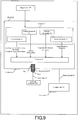
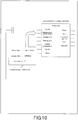
- the present embodiment has following advantages: as shown in FIG. 9 , even in case that the external equipment 40 is connected to an option board 60 installed in a slot of the PLC 10, and the command target is changed to the option board 60, as show in FIG. 10 , it is only required to change the device type in the user program 11 to the option board and change the ID to OPB 60. Moreover, distribution of the OPB 60 is taken place in the setting document 13 (the slot of the PLC 10).
- FIG. 11 and FIG. 12 are flowcharts illustrating an example of a receiving sequence (receiving of the character string A-Z).
- step s1 the serial communication unit 30 receives the character string A-Z from the serial line 35.
- step s3 the PLC 10 receives the input notification data 4.
- step s5 the serial communication unit 30 receives the output notification data 4, and learns the situation that the PLC 10 has normally received the character string A-T according to the value of the input SID response.
- step s9 the serial communication unit 30 receives the output notification data 5, and learns the situation that the PLC 10 has normally received the character string U-Z according to the value of the input SID response.
- the PLC 10 (the processor 8 of the PLC 10) reads the receiving command of the user program 11, the PLC 10 executes the receiving sequence (s3, s4, s7, s8) recorded in the system program 12.
- the receiving command of the user program 11 is as that shown in FIG. 13 , and can be recorded by using a function block, and can be inserted in a ladder circuit diagram.
- an input variable of a device port is prepared, and the command target information is input to the input variable.
- the command target information refers to a device type of the command target, an identity (ID) of the command target and an object port number (a port communicating with the PLC 10 and connected to the external equipment) of the command target.
- ID an identity of the command target
- object port number a port communicating with the PLC 10 and connected to the external equipment
- the processor 8 of the PLC 10 constructs a communication path of the serial communication unit 30 in the coupler unit 20 installed on the field network 15 based on the receiving command and the command target information read from the user program 11, address information (a distribution target of the input variable SCU 30: a connector of the coupler unit 20) corresponding to the command target information that is read from the setting document 13 set by the user, structure information of a system (a system connected to the serial communication unit 30) that is read from the structure document 14 set by the user, and a communication sequence corresponding to the receiving command that is read from the system program 12, and executes the communication sequence (to be specific: the receiving sequence).
- the present embodiment has following advantages: even if the serial communication unit 30 is changed to be directly installed in the connector of the PLC 10 as that shown in FIG. 8 , the record of the user program of FIG. 13 is unnecessary to be changed, and only the address information of the setting document 13 is required to be changed (the distribution target of the input variable SCU 30 is changed from the connector of the coupler unit 20 to the connector of the PLC 10).
- the present embodiment has following advantages: as shown in FIG. 9 , even in case that the external equipment 40 is connected to the option board 60 installed in the slot of the PLC 10, and the command target is changed to the option board 60, as show in FIG. 14 , it is only required to change the device type in the user program 11 to the option board and change the ID to OPB 60. Moreover, distribution of the OPB 60 is taken place in the setting document 13 (the slot of the PLC 10).
- the command target information (the device type, ID and port number serving as the device port variable) is recorded in the user program 11, and the address information is recorded in the setting document 13, and the structure information of the system is recorded in the structure document 14, such that the time required for changing the user program 11 along with a change of the connection position of the communication interface device (the serial communication unit 30 or the option board 60) is saved.
- the setting document 13 and the structure document 14 can be produced by using the support tool 50.
- the processor 8 of the PLC 10 reads the communication command of the user program 11 to execute the communication sequence recorded in the system program 12. Therefore, in case that a change for the communication sequence exists, it is only required to change the system program 12 of the PLC 10 without a change of the side of the serial communication unit 30.
- the processing load of the serial communication unit 30 is mitigated, such that a communication speed can be enhanced according to the capability of the PLC 10.
Landscapes
- Physics & Mathematics (AREA)
- General Physics & Mathematics (AREA)
- Engineering & Computer Science (AREA)
- Automation & Control Theory (AREA)
- Programmable Controllers (AREA)
Abstract
Description
- The invention relates to a programmable logic controller.
- A programmable logic controller (PLC) is connected to external equipment through a communication interface device. For example, the external equipment (for example, a bar code reader) adapted to serial communication is connected to a specific port of the communication interface device, and the external equipment and the PLC transceives data through the specific port. In this case, the PLC sends a command to the communication interface device to send data to the external equipment through the specific port, or sends a command to the communication interface device to receive data from the external equipment through the specific port. These commands are recorded in a user program of the PLC.
- The communication interface device is sometimes directly installed on a connector of the PLC or sometimes installed on a coupler (slave) on a field network taking the PLC as a master, and when a user records the aforementioned commands in the user program, a connection position of the communication interface device (i.e. whether the communication interface device is directly installed on the connector of the PLC or installed on the coupler on the field network) has to be recognized for recording the commands.
- Patent literature 1:
Japan Patent publication No. 9-44212 (published on February 14, 1997 - The prior art has following problems: the command has to be rewritten according to the connection position (address) of the communication interface device, and if the connection position of the communication interface deice is changed, a user program has to be accordingly changed.
- The invention reduces the time required for changing the user program along with the change of the connection position of the communication interface device.
- The invention provides a programmable logic controller, which is connected to external equipment through a communication interface device, and the programmable logic controller includes a memory, containing a user program and a setting document, where the user program records both of a command for the communication interface device and command target information thereof, and the setting document saves address information corresponding to the command target information; and a processor, reading the user program and the setting document to execute the command for the communication interface device.
- According to the above structure, the command and the command target information thereof are recorded in the user program, and the address information corresponding to the command target information is separately saved in the setting document. Therefore, in case that the connection position (address) of the communication interface device is changed, the setting document can be changed without changing the user program or changing of the user program can be set to the minimum.
- In an embodiment of the invention, the command target information includes a type, an identity and a port number of the communication interface device.
- In an embodiment of the invention, the processor executes the command based on the command target information, the address information and structure information of a system connected to the programmable logic controller and the communication interface device.
- In an embodiment of the invention, the command target information is an input variation of a function block of the command.
- In an embodiment of the invention, the communication interface device is a serial communication unit installed on a coupler unit, or on a connector of the programmable logic controller, where the coupler unit is connected to the programmable logic controller through a field network.
- In an embodiment of the invention, the communication interface device is an option board (communication board) installed in a slot of the programmable logic controller.
- In an embodiment of the invention, the memory stores a structure document recording the structure information of the system.
- The invention provides a control method of a programmable logic controller, where the programmable logic controller is connected to external equipment through a communication interface device, and the control method of the programmable logic controller includes a step of reading a user program and a setting document, where the user program records both of a command for the communication interface device and command target information thereof, and the setting document saves address information corresponding to the command target information; and a step of processing the command for the communication interface device.
- The invention provides a control program of a programmable logic controller, where the programmable logic controller is connected to external equipment through a communication interface device, and a processor of the programmable logic control executes following steps according to the control program of the programmable logic controller: a step of reading a user program and a setting document, where the user program records both of a command for the communication interface device and command target information thereof, and the setting document saves address information corresponding to the command target information; and a step of processing the command for the communication interface device.
- The programmable logic controller of the invention reduces the time required for changing the user program taken place along with the change of the connection position of the communication interface device.
- In order to make the aforementioned and other features and advantages of the invention comprehensible, several exemplary embodiments accompanied with figures are described in detail below.
- The accompanying drawings are included to provide a further understanding of the invention, and are incorporated in and constitute a part of this specification. The drawings illustrate embodiments of the invention and, together with the description, serve to explain the principles of the invention.
-
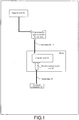
FIG. 1 is a block diagram of a connection structure of a programmable logic controller and other device. -
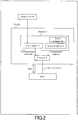
FIG. 2 is a block diagram of a structure of the programmable logic controller. -
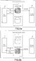
FIG. 3a and FIG. 3b are schematic diagrams illustrating data sending/receiving between the programmable logic controller and the external equipment through the serial communication unit. -
FIG. 4 is a flowchart illustrating a communication sequence between the programmable logic controller and the serial communication unit (front half steps in data sending). -
FIG. 5 is a flowchart illustrating a communication sequence between the programmable logic controller and the serial communication unit (rear half steps in data sending). -
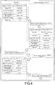
FIG. 6 is a diagram illustrating a function block of a sending command and a recording example of a user program using the function block. -
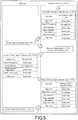
FIG. 7 is a block diagram illustrating a principle of constructing a communication path of the communication command (a programmable logic controller (PLC) → a serial communication unit installed on the coupler unit). -
FIG. 8 is a block diagram illustrating a principle of constructing a communication path of the communication command (a PLC → a serial communication unit directly installed on the PLC). -
FIG. 9 is a block diagram illustrating a principle of constructing a communication path of the communication command (a PLC → an option board installed in a slot of the PLC). -
FIG. 10 is a diagram illustrating a changing content of a user program (sending command) when a structure ofFIG. 9 is adopted. -
FIG. 11 is a flowchart illustrating a communication sequence between the programmable logic controller and the serial communication unit (front half steps in data reception). -
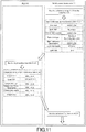
FIG. 12 is a flowchart illustrating a communication sequence between the programmable logic controller and the serial communication unit (rear half steps in data reception). -
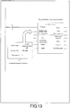
FIG. 13 is a diagram illustrating a function block of a receiving command and a recording example of a user program using the function block. -
FIG. 14 is a diagram illustrating a changing content of a user program (receiving command) when a structure ofFIG. 9 is adopted. - The embodiments of the invention are described below with reference of
FIG. 1 to FIG. 14 . As shown inFIG. 1 , a programmable logic controller (referred to as PLC hereinafter) 10 of the present embodiment is connected to acoupler unit 20 through afield network 15, and aserial communication unit 30 is connected to thecoupler unit 20, and theserial communication unit 30 is connected toexternal equipment 40 through aserial line 35. Moreover, thePLC 10 can be connected to asupport tool 50. - For an example, the
field network 15 is an Ethernet control automation technology (Ethernet CAT: trademark) network, thePLC 10 is an Ethernet CAT master, and thecoupler unit 20 is an interface used for implementing process data communication (process data objects (PDO) communication) between thePLC 10 and theserial communication unit 30 on the Ethernet CAT network. - The PLC 10 serving as the master manages the
field network 15, and monitors states of slaves (thecoupler unit 20 and the serial communication unit 30), or performs PDO communication with the slaves. - The
serial communication unit 30 performs the PDO communication with thePLC 10 through thecoupler unit 20, and performs serial communication with the external equipment 40 (serial communication equipment) through theserial line 35. Thesupport tool 50 connected to thePLC 10 is a terminal (computer, etc.) running support software, and the user uses the support software to set thefield network 15 and the slaves, or produce a user program sent to thePLC 10, or produce a setting document, etc. - The
PLC 10 has amemory 7 and aprocessor 8, thememory 7 saves auser program 11 sent by thesupport tool 50 and asystem program 12. - In the
user program 11, a communication command (for example, a sending command or a receiving command) with theexternal equipment 40 is recorded. Moreover, in thesystem program 12, a specific communication sequence corresponding to the communication command is recorded, and theprocessor 8 reads the communication command from theuser program 11 to execute the communication sequence recorded in thesystem program 12. In this way, the PLC 10 performs the PDO communication with the slaves (thecoupler unit 20 and the serial communication unit 30) through thefield network 15. - When the
PLC 10 send data, as shown inFIG. 3a , the sending data coming from thePLC 10 is sequentially transferred to a buffer of theserial communication unit 30 through thefield network 15 during each process data communication period, and is then sent to theserial line 35. - Moreover, when the
PLC 10 receives data, as shown inFIG. 3b , the receiving data coming from theserial line 35 is saved to the buffer of theserial communication unit 30, and is then transferred to thePLC 10 through thefield network 15 during each process data communication period. -
FIG. 4 andFIG. 5 are flowcharts illustrating an example of a sending sequence (sending of a character string A-Z). - First, in step S1, the
PLC 10 produces output notification data 1 (output SID=a value of "increment"/input SID response=initial value/output data type=a value of "not final"/output subsidiary information=initial value/output data length=20 bytes/output data=character string A-T), and outputs the same to thefield network 15. - Then, in step S2, the
serial communication unit 30 receives theoutput notification data 1. - Then, in step S3, the
serial communication unit 30 inputs input notification data 1 (port state=a value of "sending data existed in the buffer"/input SID= initial value/output SID response=a value of "setting output SID"/input data type=initial value/output subsidiary information=initial value/input data length=initial value/input data=initial value) to thefield network 15. - Then, in step S4, the
PLC 10 receives theinput notification data 1, and learns that theserial communication unit 30 normally receives the character string A-Z according to the value of the output SID response. - Then, in step S5, the
serial communication unit 30 saves the character string A-Z to the buffer of itself (referring toFIG. 3a ). - Then, in step S6, the
PLC 10 produces output notification data 2 (output SID=a value of "increment"/input SID response=initial value/output data type=a value of "final"/output subsidiary information=initial value/output data length=6 bytes/output data=character string U-Z), and outputs the same to thefield network 15. - Then, in step S7, the
serial communication unit 30 receives theoutput notification data 2. - Then, in step S8, the
serial communication unit 30 inputs input notification data 2 (port state=a value of "sending data existed in the buffer"/input SID=initial value/output SID response=a value of "setting output SID"/input data type=initial value/output subsidiary information=initial value/input data length=initial value/input data=initial value) to thefield network 15. - Then, in step S9, the
PLC 10 receives theinput notification data 2, and learns that theserial communication unit 30 normally receives the character string U-Z according to the value of the output SID response. - Then, in step S10, the
serial communication unit 30 saves the character string U-Z to the buffer of itself, and since the output data type of theoutput notification data 2="final", the character strings A-Z are summed up for sending to the serial line 35 (referring toFIG. 3a ). - Then, in step S11, the
PLC 10 produces output notification data 3 (output SID=a value of "no increment"/input SID response=initial value/output data type=a value of "no sending data"/output subsidiary information=initial value/output data length=initial value/output data=initial value), and outputs the same to thefield network 15. - Then, in step S12, the
serial communication unit 30 inputs input notification data 3 (port state=a value of "sending complete toggle bit variation"/input SID=initial value/output SID response=a value of "no variation"/input data type=initial value/output subsidiary information=initial value/input data length=initial value/input data=initial value) to thefield network 15, and notifies the situation of sending the character string A-Z to theserial line 35 to thePLC 10. - Then, in step S13, the
PLC 10 receives theinput notification data 3, and learns the situation that theserial communication unit 30 has sent the character string A-Z to theserial line 35 according to the value of the port state="sending complete toggle bit variation". - As described above, when the PLC 10 (the
processor 8 of the PLC 10) reads the sending command of theuser program 11, thePLC 10 executes the sending sequence (S1, S4, S6, S9, S11, S13) recorded in thesystem program 12. - The sending command of the
user program 11 is as that shown inFIG. 6 , and can be recorded by using a function block, and can be inserted in a ladder circuit diagram. - In the function block of the sending command, an input variable of a device port is prepared, and the command target information is input to the input variable. The command target information refers to a device type of a command target, an identity (ID) of the command target and an object port number (a port communicating with the
PLC 10 and connected to the external equipment) of the command target. As shown inFIG. 7 , in case that theserial communication unit 30 in thecoupler unit 20 installed on the field network is taken as the command target of the sending command, in theuser program 11, based on the specification ofFIG. 6 , the device type is the serial communication unit, the ID isSCU 30, and the port number is 1. - The
processor 8 of thePLC 10 constructs a communication path of theserial communication unit 30 in thecoupler unit 20 installed on thefield network 15 based on the sending command and the command target information read from theuser program 11, address information (a distribution target of the input variable SCU 30: a connector of the coupler unit 20) corresponding to the command target information that is read from the settingdocument 13 set by the user, structure information of a system (a system connected to the serial communication unit 30) that is read from astructure document 14 set by the user, and a communication sequence corresponding to the sending command that is read from thesystem program 12, and executes the communication sequence (to be specific: the sending sequence). - The present embodiment has following advantages: even if the
serial communication unit 30 is changed to be directly installed in the connector of thePLC 10 as that shown inFIG. 8 , the record of the user program ofFIG. 6 is unnecessary to be changed, and only the address information of the settingdocument 13 is required to be changed (the distribution target of the inputvariable SCU 30 is changed from the connector of thecoupler unit 20 to the connector of the PLC 10). Moreover, the settingdocument 13 or thestructure document 14 can be produced by using thesupport tool 50. - Therefore, the present embodiment has following advantages: as shown in
FIG. 9 , even in case that theexternal equipment 40 is connected to anoption board 60 installed in a slot of thePLC 10, and the command target is changed to theoption board 60, as show inFIG. 10 , it is only required to change the device type in theuser program 11 to the option board and change the ID toOPB 60. Moreover, distribution of theOPB 60 is taken place in the setting document 13 (the slot of the PLC 10). -
FIG. 11 andFIG. 12 are flowcharts illustrating an example of a receiving sequence (receiving of the character string A-Z). - First, in step s1, the
serial communication unit 30 receives the character string A-Z from theserial line 35. - Then, in step s2, the
serial communication unit 30 inputs input notification data 4 (port state=initial value/input SID=increment/output SID response=initial value/input data type=a value of "non-final receiving data exists"/input subsidiary information=initial value/input data length=20 bytes/input data=A-T) to thefield network 15. - Then, in step s3, the
PLC 10 receives theinput notification data 4. - Then, in step s4, the
PLC 10 produces output notification data 4 (output SID=initial value/input SID response=set input SID/output data type=initial value/output subsidiary information=initial value/output data length=initial value/output data=initial value), and outputs the same to thefield network 15, and notifies the situation of normally receiving the character string A-T to theserial communication unit 30. - Then, in step s5, the
serial communication unit 30 receives theoutput notification data 4, and learns the situation that thePLC 10 has normally received the character string A-T according to the value of the input SID response. - Then, in step s6, the
serial communication unit 30 inputs input notification data 5 (port state=a value of "detecting the end"/input SID=increment/output SID response=initial value/input data type=end of receiving data/input subsidiary information=initial value/input data length=6 bytes/input data=U-Z) to thefield network 15. - Then, in step s7, the
PLC 10 receives theinput notification data 5, and learns the situation that theserial communication unit 30 has detected the end of the receiving data according to the value of the port state="detecting the end". - Then, in step s8, the
PLC 10 produces output notification data 5 (output SID=initial value/input SID response=set input SID/output data type=initial value/output subsidiary information=initial value/output data length=initial value/output data=initial value), and outputs the same to thefield network 15, and notifies the situation of normally receiving the character string U-Z to theserial communication unit 30. - Then, in step s9, the
serial communication unit 30 receives theoutput notification data 5, and learns the situation that thePLC 10 has normally received the character string U-Z according to the value of the input SID response. - As described above, when the PLC 10 (the
processor 8 of the PLC 10) reads the receiving command of theuser program 11, thePLC 10 executes the receiving sequence (s3, s4, s7, s8) recorded in thesystem program 12. - The receiving command of the
user program 11 is as that shown inFIG. 13 , and can be recorded by using a function block, and can be inserted in a ladder circuit diagram. - In the function block of the receiving command, an input variable of a device port is prepared, and the command target information is input to the input variable. The command target information refers to a device type of the command target, an identity (ID) of the command target and an object port number (a port communicating with the
PLC 10 and connected to the external equipment) of the command target. As shown inFIG. 7 , in case that theserial communication unit 30 in thecoupler unit 20 installed on the field network is taken as the command target of the sending command, in theuser program 11, based on the specification ofFIG. 13 , the device type is the serial communication unit, the ID isSCU 30, and the port number is 1. - The
processor 8 of thePLC 10 constructs a communication path of theserial communication unit 30 in thecoupler unit 20 installed on thefield network 15 based on the receiving command and the command target information read from theuser program 11, address information (a distribution target of the input variable SCU 30: a connector of the coupler unit 20) corresponding to the command target information that is read from the settingdocument 13 set by the user, structure information of a system (a system connected to the serial communication unit 30) that is read from thestructure document 14 set by the user, and a communication sequence corresponding to the receiving command that is read from thesystem program 12, and executes the communication sequence (to be specific: the receiving sequence). - The present embodiment has following advantages: even if the
serial communication unit 30 is changed to be directly installed in the connector of thePLC 10 as that shown inFIG. 8 , the record of the user program ofFIG. 13 is unnecessary to be changed, and only the address information of the settingdocument 13 is required to be changed (the distribution target of the inputvariable SCU 30 is changed from the connector of thecoupler unit 20 to the connector of the PLC 10). - Therefore, the present embodiment has following advantages: as shown in
FIG. 9 , even in case that theexternal equipment 40 is connected to theoption board 60 installed in the slot of thePLC 10, and the command target is changed to theoption board 60, as show inFIG. 14 , it is only required to change the device type in theuser program 11 to the option board and change the ID toOPB 60. Moreover, distribution of theOPB 60 is taken place in the setting document 13 (the slot of the PLC 10). - As described above, according to the present embodiment, the command target information (the device type, ID and port number serving as the device port variable) is recorded in the
user program 11, and the address information is recorded in thesetting document 13, and the structure information of the system is recorded in thestructure document 14, such that the time required for changing theuser program 11 along with a change of the connection position of the communication interface device (theserial communication unit 30 or the option board 60) is saved. Moreover, the settingdocument 13 and thestructure document 14 can be produced by using thesupport tool 50. - Moreover, according to the present embodiment, the
processor 8 of thePLC 10 reads the communication command of theuser program 11 to execute the communication sequence recorded in thesystem program 12. Therefore, in case that a change for the communication sequence exists, it is only required to change thesystem program 12 of thePLC 10 without a change of the side of theserial communication unit 30. - Moreover, according to the present embodiment, the processing load of the
serial communication unit 30 is mitigated, such that a communication speed can be enhanced according to the capability of thePLC 10. - Moreover, according to the present embodiment, since the record of the function block shown in
FIG. 6 orFIG. 13 can be adopted, producing of the user program is easy.
Claims (9)
- A programmable logic controller (10), connected to external equipment (40) through a communication interface device, and the programmable logic controller (10) comprising:a memory (7), containing a user program (11) and a setting document (13), wherein the user program (11) records both of a command for the communication interface device and command target information thereof, and the setting document (13) saves address information corresponding to the command target information; anda processor (8), reading the user program (11) and the setting document (13) to execute the command for the communication interface device.
- The programmable logic controller (10) as claimed in claim 1, wherein the command target information comprises a type, an identity and a port number of the communication interface device.
- The programmable logic controller (10) as claimed in claim 1 or claim 2, wherein the processor (8) executes the command based on the command target information, the address information and structure information of a system connected to the communication interface device.
- The programmable logic controller (10) as claimed in any one of the claims 1-3, wherein the command target information is an input variation of a function block of the command.
- The programmable logic controller (10) as claimed in any one of the claims 1-4, wherein the communication interface device is a serial communication unit (30) installed on a coupler unit (20), or on a connector of the programmable logic controller (10), wherein the coupler unit (20) is connected to the programmable logic controller (10) through a field network (15).
- The programmable logic controller (10) as claimed in any one of the claims 1-4, wherein the communication interface device is an option board (60) installed in a slot of the programmable logic controller (10).
- The programmable logic controller (10) as claimed in claim 3, wherein the memory (7) stores a structure document (14) recording the structure information of the system.
- A control method of a programmable logic controller (10), wherein the programmable logic controller (10) is connected to external equipment (40) through a communication interface device, the control method of the programmable logic controller (10) comprising:a step of reading a user program (11) and a setting document (13), wherein the user program (11) records both of a command for the communication interface device and command target information thereof, and the setting document (13) saves address information corresponding to the command target information; andsteps (S1, S4, S6, S9, S11, S13, s3, s4, s7, s8) of processing the command for the communication interface device.
- A control program of a programmable logic controller (10), wherein the programmable logic controller (10) comprises a processor (8) and is connected to external equipment (40) through a communication interface device, the control program of the programmable logic controller (10) comprising:making the processor (8) to execute a step of reading a user program (11) and a setting document (13), wherein the user program (11) records both of a command for the communication interface device and command target information thereof, and the setting document (13) saves address information corresponding to the command target information; andsteps (S1, S4, S6, S9, S11, S13, s3, s4, s7, s8) of processing the command for the communication interface device.
Applications Claiming Priority (1)
| Application Number | Priority Date | Filing Date | Title |
|---|---|---|---|
| JP2016036444A JP6627571B2 (en) | 2016-02-26 | 2016-02-26 | Programmable controller, programmable controller control method, and programmable controller control program |
Publications (2)
| Publication Number | Publication Date |
|---|---|
| EP3211495A1 true EP3211495A1 (en) | 2017-08-30 |
| EP3211495B1 EP3211495B1 (en) | 2021-06-09 |
Family
ID=57544341
Family Applications (1)
| Application Number | Title | Priority Date | Filing Date |
|---|---|---|---|
| EP16203706.3A Active EP3211495B1 (en) | 2016-02-26 | 2016-12-13 | Programmable logic controller, control method thereof and control program thereof |
Country Status (4)
| Country | Link |
|---|---|
| US (1) | US10353370B2 (en) |
| EP (1) | EP3211495B1 (en) |
| JP (1) | JP6627571B2 (en) |
| CN (1) | CN107132808B (en) |
Families Citing this family (6)
| Publication number | Priority date | Publication date | Assignee | Title |
|---|---|---|---|---|
| JP6897494B2 (en) | 2017-10-26 | 2021-06-30 | オムロン株式会社 | Control system, control system communication control method, and relay device |
| JP6954190B2 (en) | 2018-03-12 | 2021-10-27 | オムロン株式会社 | Control system, controller, and control method |
| JP6984499B2 (en) * | 2018-03-12 | 2021-12-22 | オムロン株式会社 | FA (Factory Automation) system, controller, and control method |
| JP6922793B2 (en) * | 2018-03-12 | 2021-08-18 | オムロン株式会社 | Control devices, control methods, and control programs |
| JP7180158B2 (en) * | 2018-07-13 | 2022-11-30 | オムロン株式会社 | Program development device and controller |
| JP7052620B2 (en) * | 2018-07-30 | 2022-04-12 | オムロン株式会社 | Support equipment and support programs |
Citations (2)
| Publication number | Priority date | Publication date | Assignee | Title |
|---|---|---|---|---|
| JPH0944212A (en) | 1995-07-28 | 1997-02-14 | Omron Corp | Serial communication interface |
| US5713036A (en) * | 1994-05-26 | 1998-01-27 | Fanuc, Ltd. | Programmable logic controller having program for designating addresses of memory to which data indicating operating statuses of machine arc to be stored |
Family Cites Families (4)
| Publication number | Priority date | Publication date | Assignee | Title |
|---|---|---|---|---|
| TWI420389B (en) | 2011-04-29 | 2013-12-21 | Delta Electronics Inc | Human machine interface device and interface integration method thereof |
| CN104937508B (en) | 2013-03-15 | 2017-10-13 | 发纮电机株式会社 | Programable display |
| JP6135247B2 (en) * | 2013-03-29 | 2017-05-31 | オムロン株式会社 | Information processing apparatus and information processing program |
| WO2014184962A1 (en) * | 2013-05-17 | 2014-11-20 | 三菱電機株式会社 | Programmable controller and peripheral device thereof, and program for accessing table data of programmable controller |
-
2016
- 2016-02-26 JP JP2016036444A patent/JP6627571B2/en active Active
- 2016-12-13 EP EP16203706.3A patent/EP3211495B1/en active Active
- 2016-12-14 US US15/378,058 patent/US10353370B2/en active Active
- 2016-12-15 CN CN201611164031.6A patent/CN107132808B/en active Active
Patent Citations (2)
| Publication number | Priority date | Publication date | Assignee | Title |
|---|---|---|---|---|
| US5713036A (en) * | 1994-05-26 | 1998-01-27 | Fanuc, Ltd. | Programmable logic controller having program for designating addresses of memory to which data indicating operating statuses of machine arc to be stored |
| JPH0944212A (en) | 1995-07-28 | 1997-02-14 | Omron Corp | Serial communication interface |
Non-Patent Citations (1)
| Title |
|---|
| SIEMENS: "Industry Automation and Drive Technologies - SCE, TIA Training Manual, Module P01_02, PCS7 for Universities", 1 December 2010 (2010-12-01), pages 1 - 23, XP055379803, Retrieved from the Internet <URL:https://w3.siemens.com/mcms/sce/de/fortbildungen/ausbildungsunterlagen/hochschul-module/tabcardseiten/Documents/V7.0/eP01-02_hardware_configuration_RC1012.pdf> [retrieved on 20170608] * |
Also Published As
| Publication number | Publication date |
|---|---|
| JP6627571B2 (en) | 2020-01-08 |
| CN107132808B (en) | 2020-05-08 |
| US20170248932A1 (en) | 2017-08-31 |
| JP2017151934A (en) | 2017-08-31 |
| CN107132808A (en) | 2017-09-05 |
| US10353370B2 (en) | 2019-07-16 |
| EP3211495B1 (en) | 2021-06-09 |
Similar Documents
| Publication | Publication Date | Title |
|---|---|---|
| EP3211495B1 (en) | Programmable logic controller, control method thereof and control program thereof | |
| US10649820B2 (en) | Method of managing event generation for an industrial controller | |
| US8249726B2 (en) | Method and device for accessing a functional module of automation system | |
| EP3258329B1 (en) | Programmable logic controller, method for controlling programmable logic controller, and control program | |
| CN109976778B (en) | Software update method and system for vehicle electronic product, host computer and storage medium | |
| EP3594768B1 (en) | Management device, relay device, field wireless system, setting method, program, and recording medium | |
| CN111026428A (en) | System and method capable of simultaneously remotely updating FPGA firmware programs in multiple board cards on line | |
| US20100146225A1 (en) | Acyclic data transfer via a field bus coupler | |
| US9787543B2 (en) | Communication apparatus and communication method | |
| EP3767410A1 (en) | Control system, controller, and control method | |
| CN118540213A (en) | A node configuration method and related device for a secure real-time bus (SRB) | |
| CN108197062B (en) | Method, system, equipment and medium for realizing communication between single chip microcomputer and terminal equipment | |
| EP3015931B1 (en) | Plc system with a webserver and a partitioned memory | |
| CN114095303B (en) | Communication device, data transmission method and electronic device | |
| CN118796743A (en) | Data communication method, device, equipment and medium based on reduced pin bus | |
| EP2637105A1 (en) | Communication device, method and system | |
| CN100361433C (en) | Communication device using three step communication buffer storage | |
| JP4540637B2 (en) | Method and communication module for controlling access time to system bus | |
| CN114338358B (en) | Data interaction method, device, storage medium and PLC | |
| JP4873220B2 (en) | Field communication system | |
| CN111143218A (en) | Log debugging method and device suitable for 5G embedded equipment and readable storage medium | |
| US20250068575A1 (en) | Apparatus for processing incoming and/or outgoing data-elements | |
| CN103079094B (en) | The communication means of set top box main chip and front panel and Set Top Box | |
| JP2014127055A (en) | Peripheral device of plc | |
| KR102815712B1 (en) | System for communicating io-link and mehtod thereof |
Legal Events
| Date | Code | Title | Description |
|---|---|---|---|
| PUAI | Public reference made under article 153(3) epc to a published international application that has entered the european phase |
Free format text: ORIGINAL CODE: 0009012 |
|
| STAA | Information on the status of an ep patent application or granted ep patent |
Free format text: STATUS: REQUEST FOR EXAMINATION WAS MADE |
|
| 17P | Request for examination filed |
Effective date: 20161213 |
|
| AK | Designated contracting states |
Kind code of ref document: A1 Designated state(s): AL AT BE BG CH CY CZ DE DK EE ES FI FR GB GR HR HU IE IS IT LI LT LU LV MC MK MT NL NO PL PT RO RS SE SI SK SM TR |
|
| AX | Request for extension of the european patent |
Extension state: BA ME |
|
| RBV | Designated contracting states (corrected) |
Designated state(s): AL AT BE BG CH CY CZ DE DK EE ES FI FR GB GR HR HU IE IS IT LI LT LU LV MC MK MT NL NO PL PT RO RS SE SI SK SM TR |
|
| STAA | Information on the status of an ep patent application or granted ep patent |
Free format text: STATUS: EXAMINATION IS IN PROGRESS |
|
| 17Q | First examination report despatched |
Effective date: 20190204 |
|
| GRAP | Despatch of communication of intention to grant a patent |
Free format text: ORIGINAL CODE: EPIDOSNIGR1 |
|
| STAA | Information on the status of an ep patent application or granted ep patent |
Free format text: STATUS: GRANT OF PATENT IS INTENDED |
|
| INTG | Intention to grant announced |
Effective date: 20210114 |
|
| GRAS | Grant fee paid |
Free format text: ORIGINAL CODE: EPIDOSNIGR3 |
|
| GRAA | (expected) grant |
Free format text: ORIGINAL CODE: 0009210 |
|
| STAA | Information on the status of an ep patent application or granted ep patent |
Free format text: STATUS: THE PATENT HAS BEEN GRANTED |
|
| AK | Designated contracting states |
Kind code of ref document: B1 Designated state(s): AL AT BE BG CH CY CZ DE DK EE ES FI FR GB GR HR HU IE IS IT LI LT LU LV MC MK MT NL NO PL PT RO RS SE SI SK SM TR |
|
| REG | Reference to a national code |
Ref country code: GB Ref legal event code: FG4D |
|
| REG | Reference to a national code |
Ref country code: CH Ref legal event code: EP Ref country code: AT Ref legal event code: REF Ref document number: 1401022 Country of ref document: AT Kind code of ref document: T Effective date: 20210615 |
|
| REG | Reference to a national code |
Ref country code: DE Ref legal event code: R096 Ref document number: 602016059072 Country of ref document: DE |
|
| REG | Reference to a national code |
Ref country code: IE Ref legal event code: FG4D |
|
| REG | Reference to a national code |
Ref country code: LT Ref legal event code: MG9D |
|
| PG25 | Lapsed in a contracting state [announced via postgrant information from national office to epo] |
Ref country code: FI Free format text: LAPSE BECAUSE OF FAILURE TO SUBMIT A TRANSLATION OF THE DESCRIPTION OR TO PAY THE FEE WITHIN THE PRESCRIBED TIME-LIMIT Effective date: 20210609 Ref country code: LT Free format text: LAPSE BECAUSE OF FAILURE TO SUBMIT A TRANSLATION OF THE DESCRIPTION OR TO PAY THE FEE WITHIN THE PRESCRIBED TIME-LIMIT Effective date: 20210609 Ref country code: BG Free format text: LAPSE BECAUSE OF FAILURE TO SUBMIT A TRANSLATION OF THE DESCRIPTION OR TO PAY THE FEE WITHIN THE PRESCRIBED TIME-LIMIT Effective date: 20210909 Ref country code: HR Free format text: LAPSE BECAUSE OF FAILURE TO SUBMIT A TRANSLATION OF THE DESCRIPTION OR TO PAY THE FEE WITHIN THE PRESCRIBED TIME-LIMIT Effective date: 20210609 |
|
| REG | Reference to a national code |
Ref country code: AT Ref legal event code: MK05 Ref document number: 1401022 Country of ref document: AT Kind code of ref document: T Effective date: 20210609 |
|
| REG | Reference to a national code |
Ref country code: NL Ref legal event code: MP Effective date: 20210609 |
|
| PG25 | Lapsed in a contracting state [announced via postgrant information from national office to epo] |
Ref country code: RS Free format text: LAPSE BECAUSE OF FAILURE TO SUBMIT A TRANSLATION OF THE DESCRIPTION OR TO PAY THE FEE WITHIN THE PRESCRIBED TIME-LIMIT Effective date: 20210609 Ref country code: SE Free format text: LAPSE BECAUSE OF FAILURE TO SUBMIT A TRANSLATION OF THE DESCRIPTION OR TO PAY THE FEE WITHIN THE PRESCRIBED TIME-LIMIT Effective date: 20210609 Ref country code: NO Free format text: LAPSE BECAUSE OF FAILURE TO SUBMIT A TRANSLATION OF THE DESCRIPTION OR TO PAY THE FEE WITHIN THE PRESCRIBED TIME-LIMIT Effective date: 20210909 Ref country code: GR Free format text: LAPSE BECAUSE OF FAILURE TO SUBMIT A TRANSLATION OF THE DESCRIPTION OR TO PAY THE FEE WITHIN THE PRESCRIBED TIME-LIMIT Effective date: 20210910 Ref country code: LV Free format text: LAPSE BECAUSE OF FAILURE TO SUBMIT A TRANSLATION OF THE DESCRIPTION OR TO PAY THE FEE WITHIN THE PRESCRIBED TIME-LIMIT Effective date: 20210609 |
|
| PG25 | Lapsed in a contracting state [announced via postgrant information from national office to epo] |
Ref country code: ES Free format text: LAPSE BECAUSE OF FAILURE TO SUBMIT A TRANSLATION OF THE DESCRIPTION OR TO PAY THE FEE WITHIN THE PRESCRIBED TIME-LIMIT Effective date: 20210609 Ref country code: PT Free format text: LAPSE BECAUSE OF FAILURE TO SUBMIT A TRANSLATION OF THE DESCRIPTION OR TO PAY THE FEE WITHIN THE PRESCRIBED TIME-LIMIT Effective date: 20211011 Ref country code: NL Free format text: LAPSE BECAUSE OF FAILURE TO SUBMIT A TRANSLATION OF THE DESCRIPTION OR TO PAY THE FEE WITHIN THE PRESCRIBED TIME-LIMIT Effective date: 20210609 Ref country code: RO Free format text: LAPSE BECAUSE OF FAILURE TO SUBMIT A TRANSLATION OF THE DESCRIPTION OR TO PAY THE FEE WITHIN THE PRESCRIBED TIME-LIMIT Effective date: 20210609 Ref country code: AT Free format text: LAPSE BECAUSE OF FAILURE TO SUBMIT A TRANSLATION OF THE DESCRIPTION OR TO PAY THE FEE WITHIN THE PRESCRIBED TIME-LIMIT Effective date: 20210609 Ref country code: SM Free format text: LAPSE BECAUSE OF FAILURE TO SUBMIT A TRANSLATION OF THE DESCRIPTION OR TO PAY THE FEE WITHIN THE PRESCRIBED TIME-LIMIT Effective date: 20210609 Ref country code: SK Free format text: LAPSE BECAUSE OF FAILURE TO SUBMIT A TRANSLATION OF THE DESCRIPTION OR TO PAY THE FEE WITHIN THE PRESCRIBED TIME-LIMIT Effective date: 20210609 Ref country code: CZ Free format text: LAPSE BECAUSE OF FAILURE TO SUBMIT A TRANSLATION OF THE DESCRIPTION OR TO PAY THE FEE WITHIN THE PRESCRIBED TIME-LIMIT Effective date: 20210609 Ref country code: EE Free format text: LAPSE BECAUSE OF FAILURE TO SUBMIT A TRANSLATION OF THE DESCRIPTION OR TO PAY THE FEE WITHIN THE PRESCRIBED TIME-LIMIT Effective date: 20210609 |
|
| PG25 | Lapsed in a contracting state [announced via postgrant information from national office to epo] |
Ref country code: PL Free format text: LAPSE BECAUSE OF FAILURE TO SUBMIT A TRANSLATION OF THE DESCRIPTION OR TO PAY THE FEE WITHIN THE PRESCRIBED TIME-LIMIT Effective date: 20210609 |
|
| REG | Reference to a national code |
Ref country code: DE Ref legal event code: R097 Ref document number: 602016059072 Country of ref document: DE |
|
| PLBE | No opposition filed within time limit |
Free format text: ORIGINAL CODE: 0009261 |
|
| STAA | Information on the status of an ep patent application or granted ep patent |
Free format text: STATUS: NO OPPOSITION FILED WITHIN TIME LIMIT |
|
| PG25 | Lapsed in a contracting state [announced via postgrant information from national office to epo] |
Ref country code: DK Free format text: LAPSE BECAUSE OF FAILURE TO SUBMIT A TRANSLATION OF THE DESCRIPTION OR TO PAY THE FEE WITHIN THE PRESCRIBED TIME-LIMIT Effective date: 20210609 |
|
| 26N | No opposition filed |
Effective date: 20220310 |
|
| PG25 | Lapsed in a contracting state [announced via postgrant information from national office to epo] |
Ref country code: AL Free format text: LAPSE BECAUSE OF FAILURE TO SUBMIT A TRANSLATION OF THE DESCRIPTION OR TO PAY THE FEE WITHIN THE PRESCRIBED TIME-LIMIT Effective date: 20210609 |
|
| PG25 | Lapsed in a contracting state [announced via postgrant information from national office to epo] |
Ref country code: MC Free format text: LAPSE BECAUSE OF FAILURE TO SUBMIT A TRANSLATION OF THE DESCRIPTION OR TO PAY THE FEE WITHIN THE PRESCRIBED TIME-LIMIT Effective date: 20210609 Ref country code: IT Free format text: LAPSE BECAUSE OF FAILURE TO SUBMIT A TRANSLATION OF THE DESCRIPTION OR TO PAY THE FEE WITHIN THE PRESCRIBED TIME-LIMIT Effective date: 20210609 |
|
| REG | Reference to a national code |
Ref country code: CH Ref legal event code: PL |
|
| GBPC | Gb: european patent ceased through non-payment of renewal fee |
Effective date: 20211213 |
|
| REG | Reference to a national code |
Ref country code: BE Ref legal event code: MM Effective date: 20211231 |
|
| PG25 | Lapsed in a contracting state [announced via postgrant information from national office to epo] |
Ref country code: LU Free format text: LAPSE BECAUSE OF NON-PAYMENT OF DUE FEES Effective date: 20211213 Ref country code: IE Free format text: LAPSE BECAUSE OF NON-PAYMENT OF DUE FEES Effective date: 20211213 Ref country code: GB Free format text: LAPSE BECAUSE OF NON-PAYMENT OF DUE FEES Effective date: 20211213 |
|
| PG25 | Lapsed in a contracting state [announced via postgrant information from national office to epo] |
Ref country code: FR Free format text: LAPSE BECAUSE OF NON-PAYMENT OF DUE FEES Effective date: 20211231 Ref country code: BE Free format text: LAPSE BECAUSE OF NON-PAYMENT OF DUE FEES Effective date: 20211231 |
|
| PG25 | Lapsed in a contracting state [announced via postgrant information from national office to epo] |
Ref country code: LI Free format text: LAPSE BECAUSE OF NON-PAYMENT OF DUE FEES Effective date: 20211231 Ref country code: CH Free format text: LAPSE BECAUSE OF NON-PAYMENT OF DUE FEES Effective date: 20211231 |
|
| PG25 | Lapsed in a contracting state [announced via postgrant information from national office to epo] |
Ref country code: HU Free format text: LAPSE BECAUSE OF FAILURE TO SUBMIT A TRANSLATION OF THE DESCRIPTION OR TO PAY THE FEE WITHIN THE PRESCRIBED TIME-LIMIT; INVALID AB INITIO Effective date: 20161213 |
|
| PG25 | Lapsed in a contracting state [announced via postgrant information from national office to epo] |
Ref country code: CY Free format text: LAPSE BECAUSE OF FAILURE TO SUBMIT A TRANSLATION OF THE DESCRIPTION OR TO PAY THE FEE WITHIN THE PRESCRIBED TIME-LIMIT Effective date: 20210609 |
|
| PG25 | Lapsed in a contracting state [announced via postgrant information from national office to epo] |
Ref country code: MK Free format text: LAPSE BECAUSE OF FAILURE TO SUBMIT A TRANSLATION OF THE DESCRIPTION OR TO PAY THE FEE WITHIN THE PRESCRIBED TIME-LIMIT Effective date: 20210609 |
|
| PG25 | Lapsed in a contracting state [announced via postgrant information from national office to epo] |
Ref country code: MT Free format text: LAPSE BECAUSE OF FAILURE TO SUBMIT A TRANSLATION OF THE DESCRIPTION OR TO PAY THE FEE WITHIN THE PRESCRIBED TIME-LIMIT Effective date: 20210609 |
|
| PGFP | Annual fee paid to national office [announced via postgrant information from national office to epo] |
Ref country code: DE Payment date: 20241216 Year of fee payment: 9 |
|
| PG25 | Lapsed in a contracting state [announced via postgrant information from national office to epo] |
Ref country code: TR Free format text: LAPSE BECAUSE OF FAILURE TO SUBMIT A TRANSLATION OF THE DESCRIPTION OR TO PAY THE FEE WITHIN THE PRESCRIBED TIME-LIMIT Effective date: 20210609 |