EP3211370A1 - Filterverfahren für signale, die von einer sensoreinheit ausgehen, die mindestens einen messfühler eines vektoriellen physikalischen feldes umfasst, das im wesentlichen in bezug auf zeit und raum in einem referenzrahmen konstant ist - Google Patents
Filterverfahren für signale, die von einer sensoreinheit ausgehen, die mindestens einen messfühler eines vektoriellen physikalischen feldes umfasst, das im wesentlichen in bezug auf zeit und raum in einem referenzrahmen konstant ist Download PDFInfo
- Publication number
- EP3211370A1 EP3211370A1 EP16305230.1A EP16305230A EP3211370A1 EP 3211370 A1 EP3211370 A1 EP 3211370A1 EP 16305230 A EP16305230 A EP 16305230A EP 3211370 A1 EP3211370 A1 EP 3211370A1
- Authority
- EP
- European Patent Office
- Prior art keywords
- sensor
- qef
- transformation
- mark
- filtering
- Prior art date
- Legal status (The legal status is an assumption and is not a legal conclusion. Google has not performed a legal analysis and makes no representation as to the accuracy of the status listed.)
- Pending
Links
Images


Classifications
-
- G—PHYSICS
- G01—MEASURING; TESTING
- G01C—MEASURING DISTANCES, LEVELS OR BEARINGS; SURVEYING; NAVIGATION; GYROSCOPIC INSTRUMENTS; PHOTOGRAMMETRY OR VIDEOGRAMMETRY
- G01C17/00—Compasses; Devices for ascertaining true or magnetic north for navigation or surveying purposes
- G01C17/38—Testing, calibrating, or compensating of compasses
-
- G—PHYSICS
- G01—MEASURING; TESTING
- G01C—MEASURING DISTANCES, LEVELS OR BEARINGS; SURVEYING; NAVIGATION; GYROSCOPIC INSTRUMENTS; PHOTOGRAMMETRY OR VIDEOGRAMMETRY
- G01C19/00—Gyroscopes; Turn-sensitive devices using vibrating masses; Turn-sensitive devices without moving masses; Measuring angular rate using gyroscopic effects
- G01C19/56—Turn-sensitive devices using vibrating masses, e.g. vibratory angular rate sensors based on Coriolis forces
- G01C19/5776—Signal processing not specific to any of the devices covered by groups G01C19/5607 - G01C19/5719
-
- G—PHYSICS
- G01—MEASURING; TESTING
- G01C—MEASURING DISTANCES, LEVELS OR BEARINGS; SURVEYING; NAVIGATION; GYROSCOPIC INSTRUMENTS; PHOTOGRAMMETRY OR VIDEOGRAMMETRY
- G01C21/00—Navigation; Navigational instruments not provided for in groups G01C1/00 - G01C19/00
- G01C21/04—Navigation; Navigational instruments not provided for in groups G01C1/00 - G01C19/00 by terrestrial means
- G01C21/08—Navigation; Navigational instruments not provided for in groups G01C1/00 - G01C19/00 by terrestrial means involving use of the magnetic field of the earth
-
- G—PHYSICS
- G01—MEASURING; TESTING
- G01C—MEASURING DISTANCES, LEVELS OR BEARINGS; SURVEYING; NAVIGATION; GYROSCOPIC INSTRUMENTS; PHOTOGRAMMETRY OR VIDEOGRAMMETRY
- G01C21/00—Navigation; Navigational instruments not provided for in groups G01C1/00 - G01C19/00
- G01C21/10—Navigation; Navigational instruments not provided for in groups G01C1/00 - G01C19/00 by using measurements of speed or acceleration
- G01C21/12—Navigation; Navigational instruments not provided for in groups G01C1/00 - G01C19/00 by using measurements of speed or acceleration executed aboard the object being navigated; Dead reckoning
- G01C21/16—Navigation; Navigational instruments not provided for in groups G01C1/00 - G01C19/00 by using measurements of speed or acceleration executed aboard the object being navigated; Dead reckoning by integrating acceleration or speed, i.e. inertial navigation
- G01C21/183—Compensation of inertial measurements, e.g. for temperature effects
- G01C21/185—Compensation of inertial measurements, e.g. for temperature effects for gravity
Definitions
- the invention relates to a method for filtering the signals coming from a sensor assembly comprising at least one measurement sensor sensitive to a substantially invariant vector physical field in space and time in a reference frame linked to the Earth, ie in an EF reference mark for "Earth Frame” in English.
- the invention makes it possible to reduce or separate unwanted contributions to the signal picked up by such a measurement sensor, that is to say the contributions that are added to the physical field.
- Such a method is particularly useful in the field of inertial units, a field in which the engineer is interested in creating devices for measuring the orientation of objects in space, based on the measurement of physical fields, such as the gravity or the Earth's magnetic field.
- the objective is then to provide the orientation of the object with its reference BF in the reference reference EF.
- the invention is also intended to apply to the filtering of the signal from a measurement sensor of a physical field whose behavior in space and time is known a priori.
- the physical field has a known behavior a priori, for example by the knowledge of a model of this behavior in time and space, the invention can be applied.
- Numerous devices such as mobile phones or smartphones, touch pads, mobile computers, joysticks, motion-sensing remote controls, sensor devices for measuring human movement for monitoring applications of the physical activity, whether for the general public (electronic wristbands, instrumented interactive glasses, shoe sensors), sports or medical devices, or satellite navigation system receivers, use on-board sensors, such as magnetometers, accelerometers, gyrometers, or also directional antennas (for directions of arrival directions or DOA for acronym for "Direction of Arrival" in English).
- DOA Directional Arrival
- the requested service function is to provide a measurement of the attitude of the most efficient object possible, effectively filtering the "parasitic" contributions incorporated in the signals from the sensors, due to the fact that the sensors and the system in which they are embedded have some defects (they are called “endogenous” noises), or the nature of the physical measurement performed (it will then be called “exogenous” noise).
- the present invention proposes a method that is effective both from the point of view of metrology (measurement science and its applications) and from the point of view of the quantity of calculations required, of filtering measurements from a sensor of a physical field, like the Earth's gravitational field, or the Earth's Magnetic Field (measured then by an accelerometer and a magnetometer respectively).
- the present invention also makes it possible, by means of a step of separating the signals into a contribution due to the physical fields and a contribution due to the disturbances (eigen-accelerations, magnetic disturbances, endogenous noise), to make an estimation of the orientation of a object (with its reference BF) in a user reference frame (generally a fix reference bound to the Earth formed of a horizontal plane and a vertical direction, noted here EF), the orientation being for example materialized by a matrix of rotation, a quaternion, angles according to one of the conventions of Euler or Cardan, the object being driven by a rotational and / or translational movement, and thus subject, according to its movements, to a proper acceleration and potentially to magnetic disturbances (unknown variations around a substantially uniform field in the frame linked to the Earth EF in the near environment and constant over time), and a device implementing such a method.
- a user reference frame generally a fix reference bound to the Earth formed of a horizontal plane and a vertical direction, noted here EF
- orientation estimation can solve a whole class of problems and feed many applications, such as games for which the movement of the object is used for interaction between the universe. of the game and the user, the augmented reality for which the orientation of the object is necessary to rendering augmented reality, the functions of controlling a cursor on the screen using the instrumented object, the geographical tracking, pedestrian navigation functions for which one of the basic functions is the measurement of the orientation of the instrumented object, accessories, such as instrumented bracelets, or foot sensors for the analysis of the Following ...
- attitude estimation function The function of estimating attitude from motion sensors is usually performed using accelerometers, magnetometers and gyrometers. Because of the central nature of the attitude estimation function and its presence in most motion measurement applications, it is advantageous to reduce power consumption while providing improved metrological performance.
- Obtaining the orientation of an object generally requires the implementation of several sensors, forming part of a set designated sensor assembly, motion capture device, or central attitude.
- Electromechanical microsystems or MEMS sensors can be used to build this plant, they have the advantage of being compact, low cost and low power consumption .
- These components can be combined with computation modules and embedded in a system-on-chip or System On Chip in English, combining sensors and computing capacity.
- the sensor assembly providing such a combination of MEMS sensors is often referred to as an inertial measurement unit or IMU as an acronym for "Inertial Measurement Unit” in English.
- An attitude center comprises the sensors (for example accelerometer, magnetometer and gyrometer) as well as processing means (calculation) necessary to determine the attitude.
- the magnetometer is not strictly speaking an “inertial” measurement sensor unlike the accelerometer or the gyrometer, however, it will be considered that the term “Inertial Measurement Unit” may include in its widest definition a magnetometer.
- the calculation means may be separate from the housing comprising the sensors or included in the housing.
- attitude control units in a variety of consumer applications, such as games, augmented reality, motion-based human-machine interfaces, the domain biomedical, the monitoring of physical activities, functional rehabilitation, the analysis of sports movements, the automotive, robotics, animation in three dimensions and more generally in any field in which we seek to determine or to observe a movement.
- attitude measurement or orientation based on the measurement of two non-collinear vector physical fields, ie a first vector field and a second vector field in a reference frame linked to the solid having its reference BF, substantially constant directions in a reference reference frame EF or fixed relative to EF.
- the two physical fields usually used are the Earth's gravity field and the Earth's magnetic field.
- An alternative to such physical field measurement sensors is to use high precision, low drift gyroscopes or gyroscopes, and provide attitude initialization or registration from time to time.
- the measurement of rotational speeds provided by a gyro allows, by a time integration operation, to find the orientation of the mobile to which the sensor is attached.
- this orientation is on the one hand determined to a constant, since the sensor delivers rotational speeds and does not provide the rotational position itself, and is subject to the quality of the noise and in particular the bias of the gyrometric sensor which becomes all the more important for the quality of the final result that the integration operation amplifies considerably the effects of bias, in a manner proportional to the time.
- the systems based on the measurement of two physical fields, they then naturally comprise a first triaxial sensor and a second triaxial sensor integral with the solid to measure the components of the physical fields respectively, along the axes of the sensors fixed to the solid, therefore in the reference frame.
- BF and means for determining the rotation matrix of the solid in said fixed reference EF. If the physical fields are indeed constant in the time and space related to the fixed reference frame EF (for example a reference linked to the Earth), and if the sensors provide faithful representations of these physical fields, it is then easy to calculate a orientation according to known methods by calculating the representation of the orientation of the solid by composition of the two physical field measurements using a TRIAD or QUEST type algorithm.
- the Terrestrial gravity field is considered to be oriented along the vertical of the place where the solid is present and its norm can be considered constant on the Earth. This is particularly the case for the consumer sensors envisaged.
- the sensors of the Terrestrial gravity field are based on the principles of acceleration measurements and, as soon as the sensor is set in motion in the Terrestrial reference system, the sensor measures the contributions of the gravitational field, but also the contributions due. the same movements of the solid that carries the sensor. These contributions are called clean accelerations. These contributions are of the same nature, they are both accelerations.
- the so-called clean accelerations are due to the rotational movements of the solid (rotation which generates centrifugal and centripetal accelerations at the measuring point of the sensor) and the translation movements of the solid.
- the second derivatives with respect to the time of the position coordinates of the solid constitute their own accelerations and are measured by the sensors.
- These own accelerations are exogenous contributions. They are not due to a sensor technology defect but as they are of the same nature as the acceleration of gravity, so they add up during the measurement. It can thus be seen that by nature of the measurement, for moving solids, via an acceleration sensor, it is not possible to access a measurement of the Earth's gravity field that is an example of the contributions due to the own accelerations.
- the proposed invention makes it possible to separate these contributions due to the own accelerations of the measurement of the Earth's gravity field.
- the rotational movements in the field of gravity generate signals equal to the projection of the gravitational field on the axes of the accelerometer, which generates many signals whose frequency behavior is related to the frequency behavior of rotation movements.
- the own accelerations are themselves induced by the rotational movement printed on the object (centripetal contributions, centrifugal, acceleration translation) and thus have a frequency behavior related to the frequency behavior of the rotation movements printed on the object.
- the low-pass filtering methods applied to the signals in the reference of the object BF are therefore ineffective. At most, over long periods of time, it is to be hoped that the average contribution of clean accelerations will be reduced to zero, while that of gravity will accumulate.
- the measurements of the main magnetic field of the Earth that can be picked up by a magnetometer secured to the moving object are also disturbed.
- the main terrestrial magnetic field depends on the place where one is on Earth, both in norm, that 'in inclination (angle formed between the direction of the magnetic field and the horizontal) and declination (angle formed between the direction of the geographic North Pole and the magnetic North (it is therefore an angle on the horizontal plane of the point)
- the attitude center provides its orientation with respect to the local magnetic North, which it is then possible to then simply correct, because the magnetic declination of the Earth's magnetic field is known at the place where the we are on Earth.
- the physical field that is found at the location of the measurement is also not only composed of the magnetic field of the Earth (main field) that the we know well, but also magnetic contributions of objects, big or small, which generate themselves magnetic fields contributing to the ambient field.
- These magnetic disturbances contribute to create a field participating in the ambient field, this field being constant in time, if the objects generating the magnetic field remain fixed (both in space, therefore immobile as in magnetic properties). According to the laws of magnetostatics, these contributions are all the stronger as one approaches the object.
- residential buildings, homes, offices, houses, ... including metal structures are magnetic field generators.
- the ambient magnetic field is not really invariant in space and it is difficult to know these fields. Since a compass can be disoriented in the presence of these disturbing fields, an attitude center based on the measurement of the magnetic field, which would not take into account these disturbances, could provide a magnetic North direction different from Earth's magnetic North.
- the ambient magnetic field consists of the well-known main terrestrial field, which, for limited displacements in space, can be considered as invariant (in space and also in time ) in the Terrestrial reference, and secondly by magnetic disturbances due to the objects (large or small) that constitute our environment.
- the invention applies in the same way. For example, we can consider that we know only the main magnetic field, it is constant in space and time, given the scenarios of use in which the invention is to be applied. We can also consider a spatially variable magnetic field model, either because the use scenario provides for large displacements on the Earth, or because we have a fine cartography of the ambient field in a given place.
- any field that does not conform to the known model must be filtered, which allows the invention.
- the measurement of the magnetic field by a magnetometer does not depend on the movements printed on the solid carrier of the measuring sensor. There is no, as we noted above on the accelerometer, field contribution intrinsically created by movement.
- the rotational movements printed on the moving object equipped with a vector magnetometer sensor generate signals that are variable in time, with a frequency behavior related to the printed movements, whether for the contribution of the field principal or for the contribution due to disturbances.
- the instrumented solid is potentially subject to electromagnetic fields that may occasionally disturb or more durably the measurements, by a pollution of the bandwidth in which the measurement of the magnetic field is made.
- the invention makes it possible to effectively reduce the contribution of the magnetic disturbances of the measurement, and thus to isolate the main magnetic field.
- the latter can then be used to determine the attitude of the carrier object of the sensors.
- the generally required bandwidth is from a few Hertz to a few hundred Hertz, if one wishes to capture tremors, shocks, vibrations or movements of objects printed by the human body, as a tennis racquet, a golf club ... It is thus common to adjust the sampling frequencies of the sensors to 50, 100 or 200 Hz, in order to capture the desired bandwidth for the human movement.
- the endogenous noise of the sensors is constituted for example by a contribution of thermal noise due to the electronic components. This endogenous noise comes to add to the measurement of the sensor, according to a specific behavior.
- the noise can be white (similarly taint the different areas of the spectrum) or colored (further taint the low or high frequencies). It is usually modeled as a random, white or colored phenomenon. Any sensor also has a bias (ie the sensor delivers a non-zero value called bias, even though that it would be immersed in a null field), which is also to be taken into account.
- Attitude calculation techniques based on these physical gravity and magnetic fields are therefore penalized by the presence, in the accelerometer and magnetometer measurements, of these additional contributions to the gravity and magnetic fields of the Earth.
- Several techniques are known, to eliminate as much as possible these disturbances. We have seen that the methods of frequency filtering the signals generated by the sensors can not effectively isolate the contributions of the physical fields and their perturbation.
- the most efficient techniques use gyrometers. These sensors measure the rotational speeds of the solid to which they are attached and thus provide time derivative information of the attitude of the solid. This information is complementary to acceleration and magnetic field measurements. These sensors exist in low cost, low consumption version, are widespread in consumer devices.
- the underlying idea is that the accelerometric and magnetometric sensors deliver information close to the physical field sought during the immobile or quasi-immobile phases, and that we can then calculate an orientation of the mobile in the reference of the earth EF while the Gyrometer allows him to calculate variations of the orientation of the mobile (and only variations), during the dynamic phases of movement.
- a gyrometer is often present in platforms using an accelerometer and / or a magnetometer, because it is a sensor that delivers complementary information to these two other sensors, too, this information is usually already available.
- accelerometers most mobile phones, tablets, motion-based remote controls, joysticks, motion analysis devices for health, or devices for analyzing sports movements, are equipped with gyrometers, accelerometers and magnetometers.
- This trio A, G, M, respectively for accelerometer, gyrometer and magnetometer, is thus commonly present in these mobile devices.
- the attitude centers on board mobile phones are now usually physically composed of an accelerometer, a magnetometer and a gyrometer.
- miniaturization technologies can provide these gyrometers en masse, cheaply and for a reasonable power consumption.
- the three sensors accelerometer, magnetometer, and gyrometer are activated at the same time, because all participate by the nature and the quality of the information they deliver to the constitution of elaborate functions, for example the 'attitude.
- the invention proposed here makes it possible, in an advantageous embodiment, to optimally combine the signals of a gyrometer with those of an accelerometer and / or a magnetometer, in order to optimize the filtering of the physical fields. of gravity and / or the earth's magnetic field.
- the invention can also be used to isolate clean accelerations and / or magnetic disturbances.
- the combination accelerometer A and Magnetometer M makes it possible to determine the attitude of the solid.
- the gyrometer can take over while the accelerometric and magnetometric data are made unreliable.
- the gyrometer is thus used as a data provider supplying techniques that may be referred to as "interpolation" techniques between two reliable orientations provided by the accelerometer and / or the magnetometer.
- These techniques therefore consist in making more confidence in the measurements of the speeds of rotation (delivered by the gyrometer) during the dynamic phases of movement (which generate own accelerations), or during the measurement phases of disturbed magnetic fields, and conversely, in more confidence in the measurements of accelerations and / or magnetic fields in more stationary phases or phases without magnetic disturbances.
- the present invention exploits all the information present in the accelerometric, magnetic and gyrometric signals to optimally isolate gravity fields and / or the Earth's magnetic field.
- Kalman filter Known methods using an observer or calculator are generally based on the use of a Kalman filter.
- the advantage of this technique is to allow data fusion while taking into account the quality of the information provided by the measurements provided by the sensors and the quality of the kinetic state evolution model.
- the extended Kalman filter with EKF acronym for "Extended Kalman Filter” is particularly used in the English language; this one is fast and simple to implement, one of its applications to the capture of movement is notably described in the document " Quaternion-based extended Kalman filter for orientation determination by inertial and magnetic sensing ", SABATINI AM, IEEE Transactions on Biomedical Engineering, 2006, 53 (7) ).
- the quality of the measurements injected into the filter is of great importance, and in particular the confidence that one gives to their value.
- the measurements comprise an informative part directly related to the orientation of the moving object and a disturbing part whose nature depends on the sensor considered.
- it is about clean acceleration for measurements provided by the accelerometers, and magnetic disturbances for the measurements delivered by the magnetometer. It would be possible to incorporate sensor faults, including noise and bias for gyrometers and magnetometers.
- This method however has the disadvantage of requiring the use of a large computing power. It presents mainly, from the metrological point of view, the detection of the existence of the disturbances remains rough and the technique of estimation of the undisturbed measurements is empirical. The detection of disturbances is generally made on the basis of observation of the calculation of the modulus of the measured field. In the undisturbed case, the field of gravity and the main magnetic field have a constant modulus equal to the value of the field of gravity (ie 1 G, or about 9.81 ms 2 ) and to the value of the module of the main magnetic field (which depends on the location of the measurement on the Earth, for example 45000nT at the position of the city of Grenoble).
- This technique detects disturbances and thus manages the confidence that is given to accelerometric and magnetometric data. This technique is applicable to moving objects because the measurement module does not depend on the orientation of the sensor, so it can be calculated at any time.
- the document FR 2976353 proposes another approach, which proposes to rely on QUEST or TRIAD type calculation methods to provide the attitude, no longer based on optimization techniques, but by de-noising beforehand, according to methods close to the previous technique the vector field measurements, which are then input of QUEST or TRIAD type calculations.
- the principle is to replace the measure of field, when the latter is tainted by significant disturbances, by a prediction of this field measurement, this prediction being made using measurements provided by a gyrometer.
- This method is interesting, but it relies however on the detection of disturbances and the exploitation of this detection for the decoupling of vector fields.
- the deception is in fact always based on disturbance detection considerations made in the sensor repository, which does not exploit all the knowledge that we have about the physical fields, which are in substantially constant effect in standard, which is easy to operate whatever the reference and therefore valid in the reference of the object, but also for each of their components, which is not used by this invention of the prior art and, secondly, the method preferentially described assumes a brutal replacement of the field measured during disturbance by its prediction made using the gyrometer, which augurs non-smooth behavior.
- the present invention proposes an original denoising method that exploits the body of knowledge, beyond the simple detection of disturbances based on the standard on the physical fields that we want to denoise. Indeed, the invention fully exploits the a priori knowledge of the physical fields that are constant in time and space at the level of the vector components individually and not only globally in norm.
- An object of the invention is to provide a high-performance method that consumes little computation and de-noise of vector fields by exploiting measurements provided by a gyrometer.
- the invention makes it possible to exploit all the knowledge, component by component or combination of these components, of the components of the physical fields on which the orientation calculation is based, and it makes it possible to "measure" continuously the estimator of the physical field, between the two extreme situations, one for which the estimator of the physical field would be equal to the measurement coming from the sensors (that is to say when there is no disturbances) and the other for which the physical field estimator would be based entirely on the gyrometer-based prediction.
- the pseudo reference mark, denoted QEF for "Quasi Earth Frame” in English, is linked to reference reference EF by a constant rotation or slowly drifting in time.
- Slowly drifting means that the bandwidth of the “slow drift” is much smaller than the bandwidth of the movements printed on the object.
- Such a method also makes it possible to greatly limit the computations, which is an advantage compared to the state of the art of methods based on observers or Kalman filters that perform orientation searches via optimization techniques. by successive approximations.
- Such a method is also completely adapted to take into account the drifts of the on-board gyrometers.
- the method does not consider the gyrometer as a perfect sensor, but takes into account on the one hand the time drift of the orientation calculated on the basis of the measurements of a gyrometer, and also the fact that this orientation is not absolute .
- Such a method makes it possible to decouple the filtering from the physical fields, which makes the estimation of each field independent of the other and consequently the error of estimation of each field is also independent of the other.
- the method can be implemented with different combinations of sensors, ie A and G, M and G or AGM.
- the fact of having a single method for these combinations is advantageous since only one calculation code is necessary, which contributes to the ease of management of the code.
- said second operator, inverse of said first operator, when said operators are rotation matrices, are the matrices transposed from one another. Note that whatever the representation of the rotation transformation operator used, it is easy to determine the inverse operator without heavy computations.
- said first operator is determined from measurements provided by a gyro linked in motion to the moving marker.
- the calculation of the operator is low cost calculation, low consumption, and can be integrated on the product without other external information.
- said first operator can be determined by integration in time of the measurements provided by said gyrometer.
- the integration calculation can for example be performed at a calculation frequency greater than the calculation frequency of the application of the first transformation, the filtering, and the second transformation.
- a hardware accelerator can advantageously perform the calculation of the integration of the gyrometer signal, at a high rate, in order to minimize the errors inherent in the integration calculation and due to the size of the time steps.
- said first operator can also be determined from measurements provided by an attitude center, an optical sensor, an electromagnetic sensor, or a mechanical sensor.
- said applied filtering is adaptive.
- this type of filtering can be iterative, recursive, which reduces the memory required.
- said applied filtering is of the high-pass type in order to extract high-frequency contributions from the measurements transformed in the pseudo reference mark.
- the method of the invention makes it possible to extract measurements unrelated to the physical fields, such as the linear acceleration for the accelerometer or the magnetic disturbances for the magnetometer
- said applied filtering is of the low-pass type in order to extract low-frequency contributions from measurements transformed in the pseudo reference reference.
- said sensor assembly comprises an accelerometer and / or a magnetometer.
- the filtering method for example by keeping only the measurements of the physical fields (thus preferably with a low-pass filter)
- the necessary information is obtained and denoised to estimate the orientation of the sensor.
- the application of the filtering method for determining the proper accelerations or disturbances makes it possible to determine the movement of the sensor, for example by its own accelerations or the magnetic environment of the sensor.
- said steps are performed simultaneously on sensor signals of the sensor assembly, from at least two measurement sensors of two distinct physical fields and non-collinear in the reference frame.
- the method further comprises a step of determining the orientation of said sensor assembly in the reference frame, by applying an orientation calculation (for example Triad or Quest) from said measurements obtained after their transformation by the stages of the first transformation, the filtering, and the second transformation.
- an orientation calculation for example Triad or Quest
- Said filtering is then preferably of a low-pass nature.
- the orientation calculation step can be moved while achieving the same result: the method can therefore further comprise an additional step of determining the orientation of said pseudo reference mark relative to the reference mark, from said measurements obtained after their transformation by the steps of the first transformation and the filtering, and before applying the second transformation on the orientation thus determined by the additional step, to finally obtain the orientation of said sensor assembly in the reference frame.
- the orientation calculation thus inserted after the filtering step makes it possible to estimate the orientation of the pseudo reference mark with respect to the reference mark.
- the application of the second transformation (which makes it possible to go from the pseudo reference mark to the moving mark) thus makes it possible to obtain the orientation of said sensor assembly in the reference mark.
- the calculation method can be implemented on board a system on chip comprising the sensors and a computing unit, on board a computing unit on board the mobile or even remotely, the signals being transmitted from the mobile unit or to the computing unit deported by means of communications.
- These means of communication may use radio techniques or more generally wireless.
- the filtering method proposed in this patent application is based on the properties of the measured physical field.
- this physical field is presented as a variable vector field in space and time in a reference reference frame EF for "Earth Frame” in English language or pseudo reference mark QEF for "Quasi Earth Frame” in English language.
- the QEF is a benchmark linked to the reference frame by a constant rotation transformation or slowly variable with time.
- slowly is meant a rotation whose dynamics is small in front of the "fast” movements potentially printed on the moving object carrying the sensors.
- this reference mark is fixed relative to the Earth.
- the physical field exhibits stability characteristics in its spatial or temporal variations in a reference reference frame linked to the Earth.
- the temporal variations are generally negligible compared to the intensity of the main field (which is defined as the constant contribution in time and space of the physical field for the data of time and space of the scenario considered), and spatial variations are usually small amplitudes in front of the intensity of the main field.
- the fields generally considered are the gravity fields or the terrestrial magnetic field, and the corresponding sensors are respectively an accelerometer A and a magnetometer M.
- the invention may, for example, also apply to any physical, artificial or natural field present in the environment and for which a suitable sensor is available.
- the magnetic field formed on the surface of the Earth has as its main contributor the natural magnetic field of terrestrial origin. It is spatially continuous and presents only very slow spatial and temporal variations on the scale of the usual scenarios.
- the temporal evolution of the Earth's magnetic field is on the scale of geological time. At most we can see a slow variation in the direction of the field over the years and centuries. Furthermore, the resolution of the sensors used, in particular for the consumer applications under consideration, makes the temporal magnetic signal derived from the geomagnetic activity (of solar origin) that adds to the natural terrestrial magnetic field can be neglected.
- This environment contributes to adding to the natural contribution of the terrestrial field a second contribution of field, always predominantly constant in time, but presenting more rapid spatial variations than those of the terrestrial magnetic field.
- the objects present in an environment generally correlated to the activity or to the human presence behave like so many small contributors to the ambient field that add their contributions to the terrestrial natural field. This is the case for buildings, potentially made up of ferromagnetic materials, vehicles, etc.
- a model generally used models the intensity of their effect in amplitude as inversely proportional to the distance from the measurement point to the field-generating object. to power two or three. The effect may be important for a measurement in the immediate vicinity of the object, but it decreases rapidly with distance and tends to fade before the intensity of the Earth's field.
- Devices based on magnetic field sensors or magnetometers are generally used for the purpose of measuring the orientation of the device relative to the terrestrial reference EF. It is thus the natural magnetic field of the Earth which represents the signal of interest.
- the movements are limited to the capabilities of the wearer of the sensor.
- the Sensor set can be moved very locally, in a range of a few meters.
- the largest displacements, representative of contexts of pedestrian mobility are of the order of a few hundred meters to a few kilometers.
- the mobile device For indoor or “indoor” movements in English, it should be noted that the mobile device is generally worn by its user, who is away from sources most important magnetic elements (floors, walls, movable elements, ). For game scenarios, or navigation in 2D or 3D computer content, the displacement is done in a much more limited capture volume.
- the ambient magnetic field has a majority contribution due to the natural terrestrial magnetic field, which can be considered as constant in space and time, added to the contributions of the environment, which have the same characteristics.
- the invention provides a method of filtering, without user intervention, disturbances that add up to the substantially constant normal physical field in time and space, using in conjunction with the signals delivered by the sensor of the physical field, a measuring the rotation of the mobile device embodying the physical field sensor. It is this rotation measurement, which the invention considers as imperfect, which makes it possible to form a transformation in rotation of the reference mark of the sensor BF (EC also denotes the reference linked to the sensor assembly which is coincidental or equivalent to the reference mark BF, because they are identical or determined relative to each other by a known and constant rotation) to the pseudo reference reference QEF. It is obvious that in the case where this measurement of rotation of the mobile device is perfect, one would know directly the transformation in rotation between the reference of the sensor BF and the reference land reference. The invention then applies again, and its purpose would then be to separate the perturbations of the signal from the constant physical fields in time and space.
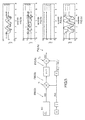
- the figure 1 illustrates the general principle of the invention.
- the pseudo reference mark QEF is considered to be linked to the EF reference mark by a constant or slowly variable rotation over time.
- the sensor assembly EC is fixedly linked in motion to a movable marker BF, movable in the reference mark EF and in the pseudo reference mark QEF.
- FILT filtering is then applied to the measurements thus transformed in the pseudo reference reference frame QEF, then a second transformation T2, inverse of said first transformation, is applied to the measurements filtered by said FILT filtering, from the reference reference mark QEF to the moving reference frame BF.
- a second transformation T2 inverse of said first transformation
- R (t) of change of reference mark in rotation between the pseudo reference mark QEF and the moving marker BF
- the second operator R -1 (t), inverse to said first operator R (t), when said operators are rotation matrices, are the transpose matrices R (t) T of one another. This allows easy calculation by matrix transposition T.
- the figure 2 it is possible to exploit data provided by a gyrometer G included in the sensor assembly to determine the first operator R (t) for transformation in rotation between the reference BF of the mobile carrying the sensors, and the QEF mark, for example by temporal integration of the measurements provided by the gyrometer G.
- This calculation can for example be performed at a calculation frequency higher than the calculation frequency of the application of the first transformation T1, FILT filtering, and the second transformation T2 . It can be performed by a specialized and efficient computing unit to perform the higher frequency calculation than the other steps of the invention to reduce the error due to the size of the time steps.
- the present invention is therefore particularly advantageous in the case of a mobile device in the terrestrial frame, therefore also in the pseudo reference frame QEF, for example, embodying an attitude center comprising at least one Gyrometer and a sensor of the physical field constant in time and space in reference reference EF.
- the pseudo reference frame QEF is therefore linked to the terrestrial reference EF by a transformation comprising an unknown constant rotation part, and a part of rotation slowly drifting in time.
- the first operator R (t) can be determined from measurements provided by another attitude controller, an optical sensor, an electromagnetic sensor, or a mechanical sensor.
- the gyrometer G delivers signals representative of the instantaneous rotational speeds of the mobile device, along the axes of the reference BF linked to the mobile device.
- the instantaneous speeds delivered by the gyrometer are delivered in the moving frame BF.
- the reference reference EF is supposed to be Galilean, unless the effects of the rotation of the Earth are not negligible compared to the performance of the gyrometer. As long as no effect (acceleration), consequence of a rotation, can be measured, a repository can be considered as inertial. Also the definition of an inertial reference depends on the accuracy of the measurements made. In the present invention, it is considered that the terrestrial reference (usually defined by a vertical vector, and a horizontal north) is Galilean.
- the integral calculation method may be implemented at a higher rate than the sampling rate of the accelerometric or magnetometric signals, advantageously on board a specialized circuit for this type of calculation. This reduces errors due to large time sampling steps.
- the orientation of an immobile device in the terrestrial frame EF thus estimated from rotational speeds is unknown to a constant rotation operator near, and it will drift slowly over time.
- the gyro thus gives access only to the value of the orientation of the mobile device in a pseudo reference reference QEF.
- the drift of the estimator is zero, while the constant rotation operator remains unknown.
- the QEF mark is then fixedly bound to the terrestrial reference mark EF by a constant but unknown rotation operator.
- the QEF mark is then linked to the terrestrial reference mark EF by a rotation operator slowly drifting in time.
- the signals coming from a gyrometer G thus make it possible to calculate, at each instant, a constant rotation unknown close and a time drift, function of the bias of the gyrometer, the orientation of the mobile in the terrestrial frame.
- the spherical filtering method proposed here directly takes into account these properties. It therefore does not assume that the Gyrometer is perfect, which is a considerable advantage of this invention, since the defects inherent in the gyrometer are taken into account.
- the method of "spherical filtering" as currently known, is particularly advantageous for devices carrying a gyrometer.
- the present invention is of particular interest for an EC sensor assembly embarking an accelerometer A and / or a magnetometer M.
- the sensors are mechanically secured to the mobile device. It is assumed that, at any moment, an orientation datum of the mobile device is available in the pseudo reference reference frame QEF, thus known to a constant orientation unknown, and possibly having a behavior drifting slowly over time with respect to the reference EF reference. We have seen that it is possible to find this orientation data of the mobile device in the pseudo reference reference QEF, for example by means of a gyro.
- the data processed by the method described allow, with the accelerometer A to separate the gravitational contribution of the own acceleration contribution.
- the described method makes it possible to separate the magnetic disturbances from the contributions of the main field. From the gravitational contribution thus obtained, it is possible to provide the angles of inclination of the device in the terrestrial reference EF. With both sensors it is then possible to provide the complete orientation of the device in the terrestrial reference EF.
- the accelerometer sensor here measures the sum of the gravitational field contributions and the own acceleration contribution. It will be considered that the geometry of the mobile device and the sensors is known and that it is thus possible to express all the signals generated by the sensors in the same frame linked to the mobile device BF or EC. We considers that the measured values forming the accelerometric signals are corrected for bias (or offsets) and gains (or sensitivity).
- R (t) -1 represents the transformation operator in rotation which makes it possible to pass from the reference mark QEF to the mark BF. It is naturally variable in time, the mobile device being deemed mobile. Note that the model of the signal delivered by the accelerometer is presented as a function of g EF , gravity vector in the terrestrial reference, and not g QEF . In the present invention, it is relied on the fact that the operator R between the EF and QEF marks is generally not known. The invention thus directly takes this majority case into account. In a majority practice case R is determined for example from the gyrometer G as on the figure 2 where it is available from another source such as on the figure 1 .
- R (t) -1 * g QEF therefore represents the acceleration contribution measured by the accelerometer A, in the reference BF of the mobile device, due to gravity. It is also a vector with three components. This contribution is naturally variable in time according to the orientations that the mobile device takes in the terrestrial reference. For a pure rotation movement of the mobile device at a given frequency, a signal contribution at this same frequency is thus observed in the measurement of the accelerometer A, due to the gravity field of the Earth.
- ap BF (t) represents the own acceleration of the mobile, in the mobile frame.
- this signal therefore has a contribution of the same frequency distribution as that of the displacement in translation that the mobile device undergoes.
- the sensor is not positioned on the instantaneous center of rotation of the mobile device, an own acceleration contribution due to the rotational speed and the distance to the center of rotation is created and adds to the contribution. due to translation movements.
- the signal therefore has a contribution of the same frequency distribution as that of the rotational displacements that the mobile device undergoes. This has been seen previously.
- aw bf (t) represents the sound of the sensor in the moving reference frame BF.
- R (t) and its inverse transformation R (t) -1 are deduced from each other simply, because they are transformational operators in rotation.
- R (t) -1 is obtained by the transpose of R or R (t) t .
- the operation of calculating the inverse is represented in the figures by a transposition function.
- the signals from the sensor assembly are noted EC (t).
- EC (t) may comprise A BF (t) for the accelerometer and / or M BF (t) (noted, for the sake of simplification, A (t) and M (t) on the figure 3 ) for the magnetometer, according to the magnetometer specific notations which will be introduced below.
- the Figure 2 illustrates the process when a gyrometer G is available to estimate R (t).
- the method of the invention applies in fact perfectly for an estimator of the known rotation operator to a constant rotation matrix close and having a slow drift in time, which is particularly advantageous for gyrometer devices, which are known to present slow drifts and which make it possible to calculate an estimator with a matrix of constant rotation unknown close.
- the invention does not require the rotation transformation operator to be a perfect estimator of the change of landmark between the mobile and a reference linked to the Earth.
- the figure 3 schematically illustrates a process and system of figure 2 according to one aspect of the invention, wherein the sensor assembly comprises an accelerometer A and / or a magnetometer M.
- EC represents the sensor assembly and generates the measurements from sensors such as the accelerometer and / or the magnetometer.
- a (t) the measurements from the accelerometer
- M (t) the measurements from the magnetometer
- the results of the filtering process of the invention are denoted by A f (t) and M f (t).
- the FILT filtering can be a high-pass or a low-pass depending on the measurement contribution that is to be isolated (that is, the physical field constant in time and space in the RF frame or the own acceleration / magnetic disturbance).
- FILT filtering applied in QEF after transformation can be adaptive, for example using linear filtering variable gain or Kalman type linear filtering.
- the Figures 1, 2, 3 present advantageous practice of the filtering proposed by the invention. We understand better why these steps are beneficial and how they work in the light of figures 4 and 5 .
- the Figures 4, 4a, 4b, 4c and 4d and the Figures 5, 5a, 5b, 5c and 5d represent, respectively in the frequency space for Figures 4, 4a, 4b, 4c and 4d and in the space of time for them Figures 5, 5a, 5b, 5c and 5d , the evolution of the behavior of the signals as and when the steps of the process.
- the figure 5 presents the behavior of the signals at different stages of the method of the invention for a time slice of an acceleration signal A (t).
- the behavior of the signals is represented at four different stages of the method of the invention according to the notations of the figures 4 and 5 for the example of the figure 3 , before, during two intermediate steps and after the application of the spherical filtering method.
- FIG 4a is shown diagrammatically, frequency, the signal measured by the accelerometer A BF (t) (or noted A (t) for the sake of simplification in the figures) or the magnetometer M BF (t) (or noted M (t) ) for the sake of simplicity in the figures), in the reference BF of the mobile device.
- the figure 5a presents a time realization of A (t) (or also A BF (t)) at the same step.
- the signal includes a contribution due to the gravitation called “useful signal", in legend Figures 4, 4a, 4b, 4c and 4d , spread according to the spectral behavior of the rotational movements printed on the moving device, ie to the sensor assembly EC, or here on a strip, given as an example of 30Hz.
- This gravitational signal constitutes, in this example, the useful part of the measurement coming from the sensor. It provides the components of the Earth's gravity field along the measurement axes of the sensor in the sensor reference. It is this so-called “useful” information (at least for an application for example for estimating the orientation of the mobile in motion), to which will be added the “noises", in particular the acceleration signal specific to the mobile. .
- the gravitational contribution is used to calculate the orientation of the sensor with respect to the Earth gravity vector, which is known to be oriented vertically with respect to the Terrestrial reference.
- the useful signal is due to the Earth's magnetic field.
- the signal measured by the sensor also comprises a second contribution denoted “acceleration” according to the legend of Figures 4, 4a, 4b, 4c and 4d for the accelerometric sensor, and "disturbance” for the magnetometric sensor according to the legend of Figures 4, 4a, 4b, 4c and 4d , and spread on a band dependent on translational and rotational movements.
- acceleration denoted “acceleration” according to the legend of Figures 4, 4a, 4b, 4c and 4d
- disurbance for the magnetometric sensor according to the legend of Figures 4, 4a, 4b, 4c and 4d
- the figure 5a represents a time measurement of the sensor according to the three measurement axes where all of these three contributions (gravitation, sensor noise and clean acceleration) add up.
- the sensor assembly On the time slice of acceleration of the figure 5 , the sensor assembly is here subjected to movements of translation and rotations in the reference of the Earth. The sensor assembly is first posed, immobile, then subjected to these movements, including clean acceleration, and then rested.
- the spherical filtering method proposed in the present invention thus comprises a first transformation T1 ( figures 4 and 5 ), by a transformation operator in rotation of the mobile marker BF to the pseudo reference mark QEF, signals from the accelerometer, A (t) and / or magnetometer, M (t).
- the frequency behavior of the signals thus transformed is represented in figure 4b .
- the temporal behavior of the time realization realization of the accelerometer is represented in figure 5b .
- the rotation transformation operator T1 (t) T1 defines the transition from the reference point BF to the reference point QEF, it is reasonably considered that it drifts slowly over time, it can easily be shown that the contribution of the contribution due the gravity (or due to the earth's magnetic field) then behaves as a signal having a frequency contribution concentrated around the zero frequency and spread in frequencies according to the drift rate of R (t).
- the figure 4b shows the effect, in frequency representation, of the operator T1 on the useful signal. The power is concentrated around 0, with a spread all the more important as the drift of the operator T1 is large.
- the fact that the operator R (t) is known only at constant rotation close to the terrestrial reference frame, does not modify the frequency behavior of the contribution of the gravitational field.
- FIG 4b the effect of the transformation T1 on the three spectra of the "useful” signal, the "acceleration and disturbance” signal and the white noise of the sensor.
- the figure 5b represents a temporal realization of the accelerometer signal, after transformation by T1.
- This FILT filter may be of parameters determined in advance, but it should be noted that it is also naturally intended, in this case, to be an adaptive filter whose filtering parameters are essentially the cutoff frequency. We can thus constantly adapt the compromise between speed of reaction and quality by producing an adaptive filter.
- the value of the cut-off frequency depends on the quality of the bias of the gyrometer G, if the device comprises a gyrometer used to estimate the operator R (t) of transformation in rotation.
- the effect of the low-pass filter is to keep the entire contribution of the acceleration signal due to gravity (and / or the Earth's magnetic field), and to reduce considerably (here so in a factor of 1 to 30 ) the contribution of the white noise and that of the own acceleration (and / or magnetic disturbances). This key step therefore considerably reduces the contributions that add up to the Earth's gravity field (and / or the Earth's magnetic field).
- the majority contribution is that of the contribution of gravitational acceleration (and / or the Earth's magnetic field), which has not been distorted or attenuated by the process steps, while the other contributions have been considerably reduced in a factor depending on the cut-off frequency of the filter (here low-pass) used in the spherical filtering method, this cutoff frequency being itself dependent on the drift quality of the rotational transformation operator estimator from the mobile marker BF to the pseudo reference mark QEF.
- the figure 5d represents a time slice at the same output step of the filter of the invention. The essentially remaining contribution is that of gravity, the other contributions of clean acceleration and endogenous noise to the sensor are considerably reduced.
- the first and second transformations T1 and T2 simply consist of transforming the measurements provided by the accelerometer A and the magnetometer M into an arbitrary reference point called a pseudo reference mark.
- QEF for example calculated from the measurements of the gyrometer G.
- This reference has a constant orientation and slowly drifting unknown with respect to reference reference EF of the Earth, which the proposed invention is freed, which represents a significant advantage .
- This marker has the property of drifting slowly relative to the Earth coordinate system because of the drift of the gyro G bias.
- the data transformed in the QEF (which drifts slowly relative to a reference reference EF) presents the Frequency characteristics following: for the magnetometer M as for the accelerometer A, the good contribution of terrestrial field (respectively magnetic gravitational) is pushed down the frequency spectrum. For a drift of zero bias, which is hypothetical but which makes it possible to understand the invention in a limiting case, it would be reduced to a continuous contribution. The own acceleration contribution is always present on the entire spectrum. Without further, more precise assumptions, it is considered that the magnetic noise contributions due to spatial anomalies of field or bad calibration noise are present on the whole spectrum.
- the proposed transformation thus has the good property of separating frequentially, for the measurements of the accelerometer, the field of gravity and the proper acceleration or the endogenous noise of the sensor.
- the terrestrial natural field or Gauss field or main field includes all the effects of deep magnetic field sources.
- the field of anomalies of the terrestrial natural field includes the whole of the sources of field not included in the field of Gauss to form the ambient field by adding to the terrestrial natural field, therefore in particular all the contributions of the sources close to the surface of the Earth. It includes all the natural effects (magnetization of rocks, magnetic effect of geological events) and unnatural effects (Cars, Buildings, ).
- the ambient field is the sum of the terrestrial natural field and the field of anomalies (or field of disturbances). He is the one who can be observed.
- the main field is, for a given scenario, and therefore a scale of space and time given, the contribution of the ambient field which is essentially constant in space and time.
- the disturbance field is the contribution that adds to the main field to give the ambient field.
- the disturbance field is usually small in front of the main field.
- h QEF (t) The main physical field at the position of the magnetic sensor of the mobile device or in other words of the sensor assembly EC, in the pseudo-reference reference QEF.
- the main field is substantially invariant in space and time for the scales of the scenario considered in the EF frame.
- the QEF mark drifts slowly in the EF mark.
- h QEF has a constant majority contribution that drifts slowly over time.
- M BF (t) is the signal delivered by the onboard magnetometer M on the mobile device, which measures the ambient magnetic field.
- M BF (t) R (t) -1 * h QEF + mp BF (t) + mw BF (t).
- the senor delivers calibrated measurements, debiaelless and along orthonormal axes of the mobile marker.
- H QEF (t) designates the main field, at the magnetometer position, out of disturbance field magnetic, and expressed in QEF.
- H QEF (t) is therefore an approximately constant vector quantity over time, and we can simplify the equation by simply noting H QEF .
- mp BF (t) represents the disturbances due to the field of magnetic disturbances measured along the axes of the magnetometer.
- mw BF (t) represents the endogenous noise at the magnetometer and the system carrying the magnetometer.
- the invention provides an estimator of the magnetic field h QEF or its perturbations mp BF from the signals M BF (t) derived from the magnetometer M, and with the aid of a knowledge of the transformation operator in rotation between the reference QEF and the movable reference BF linked to the magnetometer M.
- the good constancy properties of the main field are therefore fully exploited by the invention.
- the contribution of the main field thus transformed to QEF is then a slowly drifting constant because the value of the main field is considered constant in the reference reference EF and the QEF mark drifts slowly relative to the reference EF.
- the invention and its variants are based on this finding and proposes a way to estimate either the contribution of the main field, through a low pass filter or the contribution of disturbance by a high pass filter.
- the invention proposed according to the method described above requires having a representation of the rotation of the moving object with respect to the pseudo reference mark QEF, previously noted in the form of an operator R (t). To do this, it is possible to exploit the rotation estimated by an attitude unit employing all or part of the combinations of accelerometers, gyrometers and magnetometer. It is also possible to exploit a representation of the rotation of the moving object relative to the pseudo reference reference QEF, estimated from another sensor (optical, radio, electromagnetic, mechanical). In the more conventional cases that are forced to use only one IMU to the exclusion of other external information, the gyrometer is used to form R (t) and the method is applied to the accelometric and / or magnetometric signals with R (t). ). The invention then allows either to isolate the contribution of gravity or that of the main magnetic field. Those skilled in the art will know how to exploit these isolated signals to calculate an orientation of the inertial unit in the ground reference.
- the rotation between the moving reference mark BF and the pseudo reference mark QEF can take any reference convention linked to the Earth as a pseudo reference mark QEF.
- the QEF mark must only drift "slowly” relative to the EF mark.
- the proposed invention applies. Indeed, the properties of the transformed signals described above of the main field and the variation of the contribution due to bias remain fully valid, even if the pseudo QEF reference mark chosen is not known with respect to the classical landmark ("North, East, Down") at a close rotation.
- the invention makes it possible to make optimal use of the sensors conventionally present in attitude control units, as is the gyrometer.
- the advantage is that the method of the invention takes advantage of the information provided by this sensor, considering directly in the process all its advantages and also its defects.
- it is therefore possible to replace the rotation transformation operator R (t) between the moving frame BF and the pseudo reference mark QEF by a function based on the gyrometer.
- the figures 6 , 6a, 6b and 6d highlight the results of the invention compared to the results of a direct filtering in the sensor mark, as is sometimes present in state-of-the-art techniques illustrated by the figures 6 ' , 6a, 6c, 6e .
- the figure 6 represents the process of the invention and the figure 6 ' represents the state of the art process.
- the signals of the figure 6a illustrate an example of a temporal slice of design and measured in the space of time from a three-axis accelerometer for the same experimental realization as for the scenario of the figure 5 .
- the figure 6a presents the signals at the input of the method of the invention.
- the filtered signals according to the prior art are illustrated by simple application of a low-pass filter ( Figure 6c ), and the superposition of the raw and filtered signals according to the known art (in figure 6e ).
- Figure 6c low-pass filter
- Figure 6e the superposition of the raw and filtered signals according to the known art
- Figure 6b and 6d are shown the filtered signals ( figure 6b ) according to one aspect of the invention using a gyrometer for the determination of the operator T1 and T2, and the superposition of the raw and filtered signals ( figure 6d ) according to this aspect of the invention.
- the method of the state of the art considerably deforms the signals of the gravitational field by its low-pass filtering operation while it correctly filters the clean accelerations, whereas they are correctly extracted by the process. of the invention.
- the other settings of a high-pass or low-pass filter and applied to the measurements in the moving coordinate system are also doomed to failure compared to the advantages provided by the invention.
- the gyrometers in their low cost version, or "low cost" in the English language, have bias drift which can be significant, especially insofar as the calculations performed to obtain a rotation matrix are of the integral method type, which tend to magnify bias effects. Indeed, it is common to observe drifts of several hundred degrees per hour.
- the method proposed here remains robust to these long-term drift problems in measurement. It is sufficient to adapt the cutoff frequency of the filter according to the class of bias of the sensor. Plus bias is important, the more the constant physical fields in the Earth coordinate system will tend to drift rapidly in QEF, the more it will increase the cutoff frequency to avoid damaging the physical field.
- the invention is, however, always advantageous, to the limit where the gyrometer being too inefficient no longer delivers relevant QEF information.
- the invention has been particularly described for the cases of an accelerometer and for the case of a magnetometer. It is particularly particularly relevant for devices carrying one or the other of these sensors.
- Devices comprising in addition a gyrometer are particularly suitable for the invention.
- the gyrometer makes it possible to calculate an estimate of the rotation matrix between the moving marker BF and the pseudo reference mark QEF, which makes it possible to apply the invention.
- Devices comprising a gyrometer, as well as an accelerometer and / or a magnetometer and intended to provide an orientation of the mobile relative to the terrestrial reference may advantageously apply the invention.
- the results of the filtering of the measurement of the accelerometers and the magnetometers initially transformed in the QEF frame are transformed from the pseudo reference mark QEF to the mobile mark BF and, in addition, an additional step, makes it possible to calculate the orientation of the mobile in the reference frame, for example using a method derived from TRIAD or QUEST.
- TRIAD TRIAD
- QUEST Quaternion ESTimator
- the figure 7 schematically represents a system 1 according to the invention, such as a mobile phone.
- system 1 can be implemented as a grippable device that can be moved in space by a user and whose movement and / or orientation in space can therefore be detected.
- such a portable device may be a mobile phone (for example, a cellular telephone, a telephone operating on a local area network, or any other telephone handset), a wired telephone, a personal digital assistant (PDA), a game console video, a video game control, a navigation system, a physical activity tracking device (such as a bracelet or clip), a sensor worn on the foot, or leg, a smart watch, another portable device, a device Mobile Internet (MID), personal navigation device (PND), digital camera, digital video camera, binoculars, telephoto lens, portable music device, video or multimedia player, remote control, other mobile device pocket, or a combination of one or more of these devices.
- MID personal navigation device
- PND personal navigation device
- digital camera digital video camera, binoculars, telephoto lens
- portable music device video or multimedia player
- remote control other mobile device pocket, or a combination of one or more of these devices.
- the system 1 may be a stand-alone system or may operate in conjunction with another portable device or a non-portable device such as a desktop computer, a server, etc., that can communicate with the system 1, for example, through network connections.
- the system may be able to communicate over a wired connection using any type of wired communication protocol (such as serial transmissions, parallel transmissions, packet-switched data communications, etc.) over a wireless connection (such as electromagnetic radiation, infrared radiation or other wireless technology), or a combination of one or more wired connections and one or more wireless connections.
- the system 1 comprises a sensor processing unit 2 (SPU), one or more external sensors such as the external sensor 3, an application memory 4, an application processor 5, and a screen
- SPU sensor processing unit 2
- external sensors such as the external sensor 3
- application memory 4 such as the external sensor 3
- application processor 5 such as the external sensor 4
- screen 4 such as the external sensor 3
- the external term refers to sensors 3 being external to the sensor processing unit 2, and the external sensor may be included in the system 1 or other apparatus.
- the application processor 5 can be configured to perform the various calculations and operations necessary for the general function of the system 1, and can be coupled to the sensor processing unit 2 SPU by a bus 7, which can be any which bus or appropriate interface, for example a Bus Express Peripheral Component Interconnect (PCIe), a Universal Serial Bus (USB), an Asynchronous Universal Transmitter / Receiver (UART) serial bus, an adapted advanced microcontroller bus architecture interface (AMBA), an integrated circuit bus (I2C), a digital serial digital input / output bus (SDIO), or any other equivalent.
- PCIe Peripheral Component Interconnect
- USB Universal Serial Bus
- UART Asynchronous Universal Transmitter / Receiver
- AMBA adapted advanced microcontroller bus architecture interface
- I2C integrated circuit bus
- SDIO digital serial digital input / output bus
- My application memory 4 may include programs, drivers, or other data that uses information provided by the sensor processing unit 2.
- the sensor processing unit 2 comprises a sensor processor 8, a memory 9, and a sensor assembly 10.
- the memory 9 comprises data 10 and algorithms 11 for carrying out operations as described in FIGS. steps of the invention.
- the sensor processor may include a dedicated unit for performing specific operations such as the fast rate gyro integration operation. The other steps of the invention can then either be processed in another more generic computing unit of the sensor processor, or on board the application processor.
- the sensor assembly 10 may comprise an accelerometer, and / or a gyroscope, and / or a magnetometer, and / or a pressure sensor, and / or a temperature sensor ...
- the sensor assembly internal 10 can use the MEMS techniques for the integration of the sensor processing unit 2.
- the components of the sensor processing unit 2, such as the 8 sensor processor and the various sensors 10, can be integrated into a single chip or a set of chips.
- the memory 9 and the sensor assembly 10 may be coupled to the sensor processor 8 by a bus 13, which may be any suitable bus or interface.
- an external sensor 3 as shown is a sensor on board the device 1 which is not integrated in the sensor processing unit 2.
- An accelerometer and / or a gyroscope and / or any other sensor used in the The techniques of the present invention may be implemented as an internal or external sensor.
- the application processor 5 and / or the sensor processor 8 may be one or more microprocessors, central processing units (CPUs), or other processors that execute software programs for system1 or other applications related to system functionality1.
- various software application programs such as menu navigation, gaming, camera control, navigation software, and telephone software, or a wide variety of other software and functional interfaces may be concerned.
- multiple different applications may be provided on the same system 1, and in some of these embodiments, multiple applications may operate simultaneously on the system 1.
- Multiple software layers may be provided on a readable medium by computer such as electronic memory or other storage medium such as a hard disk, an optical disk, a flash drive, etc., for use with the application processor 5 and the sensor processor 8.
- an operating system layer may be provided for system 1 to control and manage real-time system resources, enable application software functions, and other layers and interface application programs with other software and system functions 1.
- one or more layers of the motion algorithm may provide motion algorithms for lower level processing of sensor raw data provided by internal or external sensors.
- a sensor device driver layer may provide a software interface to the hardware sensors of the system 1. Some or all of these layers may be provided in the application memory 4 for access by the application processor 5 to the memory 9 for access by the sensor processor 8, or in any other suitable architecture.
- the steps of the method described above can be performed by one or more programmable processors executing a computer program for performing the functions of the invention by acting on input data and generating output data.
- a computer program can be written in any programming language, such as compiled or interpreted languages, and the computer program can be deployed in any form, including as a standalone program or as a subprogram or function, or any other form suitable for use in a computing environment.
- a computer program can be deployed to run on a computer or multiple computers on a single site or on multiple sites distributed and interconnected by a communication network.
Landscapes
- Engineering & Computer Science (AREA)
- Remote Sensing (AREA)
- Radar, Positioning & Navigation (AREA)
- Physics & Mathematics (AREA)
- General Physics & Mathematics (AREA)
- Automation & Control Theory (AREA)
- Signal Processing (AREA)
- Life Sciences & Earth Sciences (AREA)
- Environmental & Geological Engineering (AREA)
- General Life Sciences & Earth Sciences (AREA)
- Geology (AREA)
- Gyroscopes (AREA)
Priority Applications (2)
| Application Number | Priority Date | Filing Date | Title |
|---|---|---|---|
| EP16305230.1A EP3211370A1 (de) | 2016-02-29 | 2016-02-29 | Filterverfahren für signale, die von einer sensoreinheit ausgehen, die mindestens einen messfühler eines vektoriellen physikalischen feldes umfasst, das im wesentlichen in bezug auf zeit und raum in einem referenzrahmen konstant ist |
| US15/445,777 US10648812B2 (en) | 2016-02-29 | 2017-02-28 | Method for filtering the signals arising from a sensor assembly comprising at least one sensor for measuring a vector physical field which is substantially constant over time and in space in a reference frame |
Applications Claiming Priority (1)
| Application Number | Priority Date | Filing Date | Title |
|---|---|---|---|
| EP16305230.1A EP3211370A1 (de) | 2016-02-29 | 2016-02-29 | Filterverfahren für signale, die von einer sensoreinheit ausgehen, die mindestens einen messfühler eines vektoriellen physikalischen feldes umfasst, das im wesentlichen in bezug auf zeit und raum in einem referenzrahmen konstant ist |
Publications (1)
| Publication Number | Publication Date |
|---|---|
| EP3211370A1 true EP3211370A1 (de) | 2017-08-30 |
Family
ID=55754221
Family Applications (1)
| Application Number | Title | Priority Date | Filing Date |
|---|---|---|---|
| EP16305230.1A Pending EP3211370A1 (de) | 2016-02-29 | 2016-02-29 | Filterverfahren für signale, die von einer sensoreinheit ausgehen, die mindestens einen messfühler eines vektoriellen physikalischen feldes umfasst, das im wesentlichen in bezug auf zeit und raum in einem referenzrahmen konstant ist |
Country Status (2)
| Country | Link |
|---|---|
| US (1) | US10648812B2 (de) |
| EP (1) | EP3211370A1 (de) |
Families Citing this family (2)
| Publication number | Priority date | Publication date | Assignee | Title |
|---|---|---|---|---|
| FR3069068B1 (fr) * | 2017-07-17 | 2019-08-23 | Sysnav | Procede de localisation d'un objet evoluant dans un champ magnetique genere par un ensemble d'au moins trois generateurs magnetiques |
| CN111665396B (zh) * | 2020-03-05 | 2023-04-07 | 深圳市环境监测中心站(深圳市有机物测试与环境设备检测中心) | 信号处理方法、装置和电磁场监测探头 |
Citations (5)
| Publication number | Priority date | Publication date | Assignee | Title |
|---|---|---|---|---|
| WO2010007160A1 (fr) | 2008-07-18 | 2010-01-21 | Movea S.A | Procede d'estimation ameliore de l'orientation d'un objet et centrale d'attitude mettant en oeuvre un tel procede |
| US20120075109A1 (en) * | 2010-09-28 | 2012-03-29 | Xianghui Wang | Multi sensor position and orientation system |
| US20120176492A1 (en) * | 2011-01-11 | 2012-07-12 | Qualcomm Incorporated | Camera-based inertial sensor alignment for pnd |
| FR2976353A1 (fr) | 2011-06-07 | 2012-12-14 | Movea | Procede d'estimation simplifie de l'orientation d'un objet et centrale d'attitude mettant en oeuvre un tel procede |
| US20150346003A1 (en) * | 2012-12-18 | 2015-12-03 | Movea | Iterative method of determining a bias of a sensor for measuring a substantially continuous physical vector field |
Family Cites Families (3)
| Publication number | Priority date | Publication date | Assignee | Title |
|---|---|---|---|---|
| FR2951825B1 (fr) * | 2009-10-26 | 2012-04-20 | Movea | Systeme et procede de comptage de changements de direction d'une personne |
| WO2012072961A2 (fr) * | 2010-12-01 | 2012-06-07 | Commissariat à l'énergie atomique et aux énergies alternatives | Procede et systeme de determination de valeurs de parametres representatifs d'un mouvement d'au moins deux membres d'une entite representee sous la forme d'une chaine articulee |
| KR20130127991A (ko) * | 2010-12-01 | 2013-11-25 | 꼼미사리아 아 레네르지 아토미끄 에뜨 옥스 에너지스 앨터네이티브즈 | 이동체의 경로를 추정하는 방법 및 시스템 |
-
2016
- 2016-02-29 EP EP16305230.1A patent/EP3211370A1/de active Pending
-
2017
- 2017-02-28 US US15/445,777 patent/US10648812B2/en active Active
Patent Citations (5)
| Publication number | Priority date | Publication date | Assignee | Title |
|---|---|---|---|---|
| WO2010007160A1 (fr) | 2008-07-18 | 2010-01-21 | Movea S.A | Procede d'estimation ameliore de l'orientation d'un objet et centrale d'attitude mettant en oeuvre un tel procede |
| US20120075109A1 (en) * | 2010-09-28 | 2012-03-29 | Xianghui Wang | Multi sensor position and orientation system |
| US20120176492A1 (en) * | 2011-01-11 | 2012-07-12 | Qualcomm Incorporated | Camera-based inertial sensor alignment for pnd |
| FR2976353A1 (fr) | 2011-06-07 | 2012-12-14 | Movea | Procede d'estimation simplifie de l'orientation d'un objet et centrale d'attitude mettant en oeuvre un tel procede |
| US20150346003A1 (en) * | 2012-12-18 | 2015-12-03 | Movea | Iterative method of determining a bias of a sensor for measuring a substantially continuous physical vector field |
Non-Patent Citations (1)
| Title |
|---|
| SABATINI A.M.: "Quaternion-based extended Kalman filter for determination orientation by inertial and magnetic sensing", IEEE TRANSACTIONS ON BIOMEDICAL ENGINEERING, vol. 53, no. 7, 2006 |
Also Published As
| Publication number | Publication date |
|---|---|
| US10648812B2 (en) | 2020-05-12 |
| US20170248423A1 (en) | 2017-08-31 |
Similar Documents
| Publication | Publication Date | Title |
|---|---|---|
| EP1984696B1 (de) | Bewegungserfassungsvorrichtung und entsprechendes verfahren | |
| EP2718670B1 (de) | Vereinfachtes verfahren zur schätzung der ausrichtung eines objekts und lagesensor zur durchführung dieses verfahrens | |
| EP3213033B1 (de) | Verfahren zur schätzung eines navigationszustands, der in bezug auf beobachtbarkeit eingeschränkt ist | |
| EP3658921B1 (de) | Verfahren zur kalibrierung eines magnetometers | |
| EP3071934B1 (de) | Ausrichtungsverfahren für ein trägheitsnavigationssystem | |
| EP3807594B1 (de) | Verfahren zum kalibrieren von in einem objekt montierten magnetometern | |
| EP1724592A1 (de) | System zur Schätzung der Geschwindigkeit eines Luftschiffs und Anwendung dieses Systems auf die Erfassung von Hindernissen | |
| EP1886517A2 (de) | Verfahren und einrichtung zum finden eines endgeräts in einem drahtlosen lokalen netzwerk | |
| WO2016156602A1 (fr) | Procédé de suivi de navigation d'un porteur mobile avec un filtre de kalman étendu | |
| EP2307943A1 (de) | Zeiger mit durch datenzusammenführung aufgelöster bewegungserfassung | |
| FR2854301A1 (fr) | Procede de transmission de donnees representant la position dans l'espace d'une camera video et systeme de mise en oeuvre du procede | |
| FR2934043A1 (fr) | Procede d'estimation ameliore de l'orientation d'un objet et centrale d'attitude mettant en oeuvre un tel procede | |
| EP1969314B1 (de) | Verfahren zur schätzung einer bewegung eines festkörpers | |
| FR3042266A1 (fr) | Procede d'estimation du mouvement d'un pieton | |
| FR3015072A1 (fr) | Procede de determination de l'orientation d'un repere capteur lie a un terminal mobile muni d'un ensemble capteur, porte par un utilisateur et comprenant au moins un capteur de mouvement lie en mouvement | |
| FR2922300A1 (fr) | PROCEDE DE DETERMINATION DE l'ATTITUDE, DE LA POSITION ET DE LA VITESSE D'UN ENGIN MOBILE | |
| Karaim et al. | Low-cost IMU data denoising using Savitzky-Golay filters | |
| EP3211370A1 (de) | Filterverfahren für signale, die von einer sensoreinheit ausgehen, die mindestens einen messfühler eines vektoriellen physikalischen feldes umfasst, das im wesentlichen in bezug auf zeit und raum in einem referenzrahmen konstant ist | |
| EP3652501B1 (de) | Verfahren zur schätzung der bewegung eines sich in einem magnetfeld bewegenden objekts | |
| FR3069329A1 (fr) | Procede et dispositif de mesure du champ magnetique par des magnetometres | |
| WO2014095476A1 (fr) | Procede iteratif de determination d'un biais d'un capteur de mesure d'un champ physique vectoriel sensiblement continu | |
| EP3655724B1 (de) | Verfahren zur schätzung der bewegung eines sich in einem magnetfeld bewegenden objekts | |
| WO2019239063A1 (fr) | Procédé de calibration d'un gyromètre équipant un objet | |
| EP2577225B1 (de) | Vorrichtung und verfahren zur bestimmung der tiefendaten von einem optischen, beweglichen sensor | |
| FR3069317A1 (fr) | Procede d'estimation du mouvement d'un objet evoluant dans un environnement et un champ magnetique |
Legal Events
| Date | Code | Title | Description |
|---|---|---|---|
| PUAI | Public reference made under article 153(3) epc to a published international application that has entered the european phase |
Free format text: ORIGINAL CODE: 0009012 |
|
| STAA | Information on the status of an ep patent application or granted ep patent |
Free format text: STATUS: THE APPLICATION HAS BEEN PUBLISHED |
|
| AK | Designated contracting states |
Kind code of ref document: A1 Designated state(s): AL AT BE BG CH CY CZ DE DK EE ES FI FR GB GR HR HU IE IS IT LI LT LU LV MC MK MT NL NO PL PT RO RS SE SI SK SM TR |
|
| AX | Request for extension of the european patent |
Extension state: BA ME |
|
| STAA | Information on the status of an ep patent application or granted ep patent |
Free format text: STATUS: REQUEST FOR EXAMINATION WAS MADE |
|
| 17P | Request for examination filed |
Effective date: 20180228 |
|
| RBV | Designated contracting states (corrected) |
Designated state(s): AL AT BE BG CH CY CZ DE DK EE ES FI FR GB GR HR HU IE IS IT LI LT LU LV MC MK MT NL NO PL PT RO RS SE SI SK SM TR |
|
| STAA | Information on the status of an ep patent application or granted ep patent |
Free format text: STATUS: EXAMINATION IS IN PROGRESS |
|
| 17Q | First examination report despatched |
Effective date: 20210616 |
|
| STAA | Information on the status of an ep patent application or granted ep patent |
Free format text: STATUS: EXAMINATION IS IN PROGRESS |