EP3211181A1 - Seal with integral clip and method of sealing - Google Patents
Seal with integral clip and method of sealing Download PDFInfo
- Publication number
- EP3211181A1 EP3211181A1 EP17157961.8A EP17157961A EP3211181A1 EP 3211181 A1 EP3211181 A1 EP 3211181A1 EP 17157961 A EP17157961 A EP 17157961A EP 3211181 A1 EP3211181 A1 EP 3211181A1
- Authority
- EP
- European Patent Office
- Prior art keywords
- split
- seal
- edge
- ring seal
- sealing lobe
- Prior art date
- Legal status (The legal status is an assumption and is not a legal conclusion. Google has not performed a legal analysis and makes no representation as to the accuracy of the status listed.)
- Granted
Links
- 238000007789 sealing Methods 0.000 title claims abstract description 102
- 238000000034 method Methods 0.000 title claims description 10
- 239000007789 gas Substances 0.000 description 36
- 230000000712 assembly Effects 0.000 description 8
- 238000000429 assembly Methods 0.000 description 8
- 230000003068 static effect Effects 0.000 description 4
- 238000001816 cooling Methods 0.000 description 3
- 238000005304 joining Methods 0.000 description 3
- 230000008646 thermal stress Effects 0.000 description 3
- PXHVJJICTQNCMI-UHFFFAOYSA-N Nickel Chemical compound [Ni] PXHVJJICTQNCMI-UHFFFAOYSA-N 0.000 description 2
- 230000004323 axial length Effects 0.000 description 2
- 230000008901 benefit Effects 0.000 description 2
- 238000010276 construction Methods 0.000 description 2
- 230000003247 decreasing effect Effects 0.000 description 2
- 239000000446 fuel Substances 0.000 description 2
- 230000003116 impacting effect Effects 0.000 description 2
- 238000010348 incorporation Methods 0.000 description 2
- 230000000670 limiting effect Effects 0.000 description 2
- 238000004519 manufacturing process Methods 0.000 description 2
- 239000000463 material Substances 0.000 description 2
- 238000012986 modification Methods 0.000 description 2
- 230000004048 modification Effects 0.000 description 2
- 230000036961 partial effect Effects 0.000 description 2
- 229920000049 Carbon (fiber) Polymers 0.000 description 1
- 230000002411 adverse Effects 0.000 description 1
- 229910045601 alloy Inorganic materials 0.000 description 1
- 239000000956 alloy Substances 0.000 description 1
- 230000004888 barrier function Effects 0.000 description 1
- 239000004917 carbon fiber Substances 0.000 description 1
- 239000000919 ceramic Substances 0.000 description 1
- 230000008859 change Effects 0.000 description 1
- 230000001010 compromised effect Effects 0.000 description 1
- 239000012141 concentrate Substances 0.000 description 1
- 230000007423 decrease Effects 0.000 description 1
- 239000012530 fluid Substances 0.000 description 1
- 239000003292 glue Substances 0.000 description 1
- 230000007246 mechanism Effects 0.000 description 1
- VNWKTOKETHGBQD-UHFFFAOYSA-N methane Chemical compound C VNWKTOKETHGBQD-UHFFFAOYSA-N 0.000 description 1
- 229910052759 nickel Inorganic materials 0.000 description 1
- 230000009467 reduction Effects 0.000 description 1
- 230000002829 reductive effect Effects 0.000 description 1
- 238000005096 rolling process Methods 0.000 description 1
- 238000000926 separation method Methods 0.000 description 1
Images


Classifications
-
- F—MECHANICAL ENGINEERING; LIGHTING; HEATING; WEAPONS; BLASTING
- F01—MACHINES OR ENGINES IN GENERAL; ENGINE PLANTS IN GENERAL; STEAM ENGINES
- F01D—NON-POSITIVE DISPLACEMENT MACHINES OR ENGINES, e.g. STEAM TURBINES
- F01D11/00—Preventing or minimising internal leakage of working-fluid, e.g. between stages
- F01D11/003—Preventing or minimising internal leakage of working-fluid, e.g. between stages by packing rings; Mechanical seals
-
- F—MECHANICAL ENGINEERING; LIGHTING; HEATING; WEAPONS; BLASTING
- F01—MACHINES OR ENGINES IN GENERAL; ENGINE PLANTS IN GENERAL; STEAM ENGINES
- F01D—NON-POSITIVE DISPLACEMENT MACHINES OR ENGINES, e.g. STEAM TURBINES
- F01D11/00—Preventing or minimising internal leakage of working-fluid, e.g. between stages
- F01D11/005—Sealing means between non relatively rotating elements
-
- F—MECHANICAL ENGINEERING; LIGHTING; HEATING; WEAPONS; BLASTING
- F01—MACHINES OR ENGINES IN GENERAL; ENGINE PLANTS IN GENERAL; STEAM ENGINES
- F01D—NON-POSITIVE DISPLACEMENT MACHINES OR ENGINES, e.g. STEAM TURBINES
- F01D25/00—Component parts, details, or accessories, not provided for in, or of interest apart from, other groups
- F01D25/24—Casings; Casing parts, e.g. diaphragms, casing fastenings
- F01D25/246—Fastening of diaphragms or stator-rings
-
- F—MECHANICAL ENGINEERING; LIGHTING; HEATING; WEAPONS; BLASTING
- F02—COMBUSTION ENGINES; HOT-GAS OR COMBUSTION-PRODUCT ENGINE PLANTS
- F02C—GAS-TURBINE PLANTS; AIR INTAKES FOR JET-PROPULSION PLANTS; CONTROLLING FUEL SUPPLY IN AIR-BREATHING JET-PROPULSION PLANTS
- F02C7/00—Features, components parts, details or accessories, not provided for in, or of interest apart form groups F02C1/00 - F02C6/00; Air intakes for jet-propulsion plants
- F02C7/28—Arrangement of seals
-
- F—MECHANICAL ENGINEERING; LIGHTING; HEATING; WEAPONS; BLASTING
- F16—ENGINEERING ELEMENTS AND UNITS; GENERAL MEASURES FOR PRODUCING AND MAINTAINING EFFECTIVE FUNCTIONING OF MACHINES OR INSTALLATIONS; THERMAL INSULATION IN GENERAL
- F16J—PISTONS; CYLINDERS; SEALINGS
- F16J15/00—Sealings
- F16J15/02—Sealings between relatively-stationary surfaces
- F16J15/06—Sealings between relatively-stationary surfaces with solid packing compressed between sealing surfaces
- F16J15/067—Split packings
-
- F—MECHANICAL ENGINEERING; LIGHTING; HEATING; WEAPONS; BLASTING
- F16—ENGINEERING ELEMENTS AND UNITS; GENERAL MEASURES FOR PRODUCING AND MAINTAINING EFFECTIVE FUNCTIONING OF MACHINES OR INSTALLATIONS; THERMAL INSULATION IN GENERAL
- F16J—PISTONS; CYLINDERS; SEALINGS
- F16J15/00—Sealings
- F16J15/02—Sealings between relatively-stationary surfaces
- F16J15/06—Sealings between relatively-stationary surfaces with solid packing compressed between sealing surfaces
- F16J15/08—Sealings between relatively-stationary surfaces with solid packing compressed between sealing surfaces with exclusively metal packing
- F16J15/0887—Sealings between relatively-stationary surfaces with solid packing compressed between sealing surfaces with exclusively metal packing the sealing effect being obtained by elastic deformation of the packing
-
- F—MECHANICAL ENGINEERING; LIGHTING; HEATING; WEAPONS; BLASTING
- F05—INDEXING SCHEMES RELATING TO ENGINES OR PUMPS IN VARIOUS SUBCLASSES OF CLASSES F01-F04
- F05D—INDEXING SCHEME FOR ASPECTS RELATING TO NON-POSITIVE-DISPLACEMENT MACHINES OR ENGINES, GAS-TURBINES OR JET-PROPULSION PLANTS
- F05D2240/00—Components
- F05D2240/55—Seals
- F05D2240/57—Leaf seals
Definitions
- the present application relates generally to seal assemblies, and more particularly to multi-ply split-ring seals.
- a standard full-loop W-seal used between two static components in a gas turbine engine compressor or turbine section has a tendency to be inadvertently pinched due to blind assembly of surrounding components and delicate construction, and a tendency to buckle during operation due to thermal expansion.
- a seal assembly for a gas turbine engine includes first and second split-ring seals.
- the first split-ring seal includes circumferentially separated first and second ends, laterally separated first and second edges, a first sealing lobe adjacent the first edge, and a first integral clip portion adjacent the second edge.
- the first sealing lobe has a curved surface extending laterally outward from the first edge.
- the second split-ring seal is slidably received and nested in the first seal.
- the second split-ring seal includes circumferentially separated third and fourth ends and laterally separated third and fourth edges.
- a method of sealing a cavity in a gas turbine engine includes clipping a portion of a multi-ply split-ring seal to a first component of a gas turbine engine, and compressing a portion of each ply of the multi-ply seal between the first component and a second component of the gas turbine engine.
- a multi-ply seal with an integral clip and optional heat shield can facilitate assembly in a gas turbine engine and reduce or eliminate seal buckling due to thermal expansion.
- seal assemblies used in gas turbine engines, it will be understood by one skilled in the art that use of the disclosed seal assemblies is not limited to gas turbine engines, but extends to multiple applications, particularly those that use W-type or related compressible seals to form a fluid barrier between two static components.
- FIG. 1 is a quarter-sectional view of a gas turbine engine 20 that includes fan section 22, compressor section 24, combustor section 26 and turbine section 28.
- Alternative engines might include an augmenter section (not shown) among other systems or features.
- Fan section 22 drives air along bypass flow path B while compressor section 24 draws air in along core flow path C where air is compressed and communicated to combustor section 26.
- combustor section 26 air is mixed with fuel and ignited to generate a high pressure exhaust gas stream that expands through turbine section 28 where energy is extracted and utilized to drive fan section 22 and compressor section 24.
- turbofan gas turbine engine depicts a turbofan gas turbine engine
- the concepts described herein are not limited to use with turbofans as the teachings may be applied to other types of turbine engines; for example a turbine engine including a three-spool architecture in which three spools concentrically rotate about a common axis and where a low spool enables a low pressure turbine to drive a fan via a gearbox, an intermediate spool that enables an intermediate pressure turbine to drive a first compressor of the compressor section, and a high spool that enables a high pressure turbine to drive a high pressure compressor of the compressor section.
- the example engine 20 generally includes low speed spool 30 and high speed spool 32 mounted for rotation about an engine central longitudinal axis A relative to an engine static structure 36 via several bearing systems 38. It should be understood that various bearing systems 38 at various locations may alternatively or additionally be provided.
- Low speed spool 30 generally includes inner shaft 40 that connects fan 42 and low pressure (or first) compressor section 44 to low pressure (or first) turbine section 46.
- Inner shaft 40 drives fan 42 through a speed change device, such as geared architecture 48, to drive fan 42 at a lower speed than low speed spool 30.
- High-speed spool 32 includes outer shaft 50 that interconnects high pressure (or second) compressor section 52 and high pressure (or second) turbine section 54.
- Inner shaft 40 and outer shaft 50 are concentric and rotate via bearing systems 38 about engine central longitudinal axis A.
- Combustor 56 is arranged between high pressure compressor 52 and high pressure turbine 54.
- high pressure turbine 54 includes at least two stages to provide a double stage high pressure turbine 54.
- high pressure turbine 54 includes only a single stage.
- a "high pressure" compressor or turbine experiences a higher pressure than a corresponding "low pressure” compressor or turbine.
- the example low pressure turbine 46 has a pressure ratio that is greater than about 5.
- the pressure ratio of the example low pressure turbine 46 is measured prior to an inlet of low pressure turbine 46 as related to the pressure measured at the outlet of low pressure turbine 46 prior to an exhaust nozzle.
- Mid-turbine frame 58 of engine static structure 36 is arranged generally between high pressure turbine 54 and low pressure turbine 46.
- Mid-turbine frame 58 further supports bearing systems 38 in turbine section 28 as well as setting airflow entering low pressure turbine 46.
- the core airflow C is compressed by low pressure compressor 44 then by high pressure compressor 52 mixed with fuel and ignited in combustor 56 to produce high speed exhaust gases that are then expanded through high pressure turbine 54 and low pressure turbine 46.
- Mid-turbine frame 58 includes airfoils/vanes 60, which are in the core airflow path and function as an inlet guide vane for low pressure turbine 46. Utilizing vanes 60 of mid-turbine frame 58 as inlet guide vanes for low pressure turbine 46 decreases the length of low pressure turbine 46 without increasing the axial length of mid-turbine frame 58. Reducing or eliminating the number of vanes in low pressure turbine 46 shortens the axial length of turbine section 28. Thus, the compactness of gas turbine engine 20 is increased and a higher power density may be achieved.
- the disclosed gas turbine engine 20 in one example is a high-bypass geared aircraft engine.
- gas turbine engine 20 includes a bypass ratio greater than about six (6), with an example embodiment being greater than about ten (10).
- the example geared architecture 48 is an epicyclical gear train, such as a planetary gear system, star gear system or other known gear system, with a gear reduction ratio of greater than about 2.3.
- gas turbine engine 20 includes a bypass ratio greater than about ten (10:1) and the fan diameter is significantly larger than an outer diameter of low pressure compressor 44. It should be understood, however, that the above parameters are only exemplary of one embodiment of a gas turbine engine including a geared architecture and that the present disclosure is applicable to other gas turbine engines.
- FIG. 2 is a cross-sectional view of a compressor vane assembly of the gas turbine engine.
- FIG. 2 shows component 62, components 64 and 65, seal assembly 66 positioned in a forward compartment between components 62 and 64, and seal 68 positioned in an aft compartment between components 62 and 65.
- component 62 can be a compressor stator ring having vane 60, inner band 70, and outer band 72.
- Inner and outer bands 70 and 72 can be located on either side of vane 60.
- Outer band 72 can include flange 73 extending radially outward from outer band 72.
- component 64 can be a compressor support case having a flange 74 extending radially inward toward outer band 72.
- Seal assembly 66 can seal cooling cavity 75 between components 62 and 64 from core gas flow 76.
- a pressure differential across seal assembly 66 can be low, generally around 10-30 psi (69-207 kPa).
- the pressure differential across seal assembly 66 can be as high as 150 psi (1034 kPa)
- Seal 68 can serve as a prime seal; whereas seal assembly 66 can serve as a redundant seal should seal 68 be compromised.
- FIG. 2 illustrates use of seal assembly 66 in a compressor section, it will be understood by one skilled in the art that the seal assemblies of the present disclosure can be used in multiple sections of the gas turbine engine as well as a variety of devices unrelated to gas turbine engines.
- FIGS. 3 and 4 show one embodiment of seal assembly 66.
- FIG. 3 is a cross-sectional view of seal assembly 66.
- FIG. 4 is a side view of seal assembly 66 in FIG. 3 looking aftward.
- Seal assembly 66 can be a multi-ply (e.g., two-ply) split-ring seal with an integral assembly clip.
- Seal assembly 66 can include split-ring seal 80 and split-ring seal 82.
- Split-ring seal 82 can be slidably received and nested in split-ring seal 80.
- Split-ring seal 80 can include circumferentially separated ends 84 and 86 (shown in FIG. 4 ) and laterally separated edges 88 and 90 (shown in FIG. 3 ).
- split-ring 82 can include circumferentially separated ends 92 and 94 (shown in FIG. 4 ) and laterally separated edges 96 and 98 (shown in FIG. 3 ). Ends 84 and 86 can be separated from ends 92 and 94 by about 180 degrees to reduce leakage through the plies.
- a body portion of each of split-ring seal 80 and split-ring seal 82 can undulate to form a W-type or related seal having one or more turns 99a-d, capable of being compressed between first component 62 and second component 64.
- Each turn 99a-d can substantially form an approximately 180 degree arc with a convex surface facing radially inward or outward toward axially extending portions of components 62 and 64, with adjacent turns facing opposite directions.
- W-seals it will be understood by one skilled in the art that the number of undulations can be increased or decreased.
- split-ring seal assembly 66 can increase strength and rigidity of the seal assembly 66 and allow for thermal expansion without buckling, as each split-ring seal 80 and 82 is capable of slidably expanding relative to the other split-ring seal 80 and 82.
- Some leakage may occur at the interface of ends 84 and 86 and the body portion of split-ring seal 82 and at the interface of ends 92 and 94 and the body portion of split-ring seal 80.
- leakage can be minimized by closely fitting split-ring seals 80 and 82 together, and generally, any negative impact caused by small amounts of leakage is outweighed by the aforementioned benefits of the multi-ply seal assembly.
- ends 84 and 86 can be separated by a distance (d 1 ) along the circumference of split-ring seal 80 (shown in FIG. 4 ).
- ends 92 and 94 can be separated a distance (d 2 ) along the circumference of split-ring seal 82 (shown in FIG. 4 ).
- the distances d 1 and d 2 can generally be equal to one another and can be an arc length corresponding approximately to a five degree angle. However, it will be understood by one skilled in the art, that d 1 and d 2 can be varied as necessary (increased or decreased) to accommodate thermal expansion of split-ring seals 80 and 82.
- Split-ring seals 80 and 82 can have integral clip portions 100 and 102, respectively, extending circumferentially from first end 84 to second end 68 and from third end 92 to fourth end 94. Integral clip portions 100 and 102 can clip or snap on to first component 62 to retain seal assembly 66 in position during assembly.
- Traditional W-seals without integral clip portions must be tack welded, glued, or otherwise fastened to one component to maintain position during assembly. With or without fastening, traditional W-seals, particularly single-ply full-ring W-seal have a tendency to be improperly pinched between components.
- Pinching can occur due to blind assembly (inability to visually inspect positioning of the W-seal during assembly) and delicate or flimsy construction of the W-seal, which allows the W-seal to hang downward outside of an ideal positioning for assembly.
- Integral clip portions 100 and 102 can lock seal assembly 66 in position and can also provide rigidity to seal assembly 66, thereby limiting the tendency of pinching due to downward hanging.
- the use of multiple plies or split-ring seals also increases rigidity for improved assembly.
- Integral clip portion 100 can have two bent portions including axially extending portion 100a and radially extending portions 100b and 100c, extending from either side of axially extending portion 100a, and bends 100d and 100e joining axial portion 100a with radial portions 100b and 100c.
- integral clip portion 102 can have axially extending portion 102a and radially extending portions 102b and 102c, extending from either side of axially extending portion 102a, and bends 102d and 102e joining axial portion 102a with radial portions 102b and 102c.
- Axial surfaces 100a and 102a can be substantially linear in cross-section.
- Bends 100d, 100e, 102d, and 102e can have curved surfaces forming an arc correlating with an angle substantially less than 180 degrees (e.g., 90 degrees) upon assembly.
- Radially extending portions 100b and 102b can be adjacent first side 110 of first component 62.
- Radially extending portions 100c and 102c can be adjacent second side 112 of first component 62 opposite first side 110.
- the terms "radially extending” and "axial extending” are relative terms used merely for the sake of explaining illustrated embodiments, and are provided as reference to the orientation of seal assembly 66 in the disclosed gas turbine engine.
- seal assembly 66 can be disposed in other directions, in which the terms "axially extending” and “radially extending” no longer apply as used in relation to the present embodiment.
- Radially extending portions 100b and 102b can be tightly biased toward radially extending portions 100c and 102c, requiring mechanical means to open integral clip portions 100 and 102 in order to clip seal assembly 66 onto first component 62.
- the tight biasing can provide additional rigidity to seal assembly 66 during assembly and operation.
- such tight biasing may not be necessary for all applications and can be modified as desired or as necessary.
- integral clip portions 100 and 102 alleviate the need for tack welds, glue, or similar means of fastening, such mechanisms can be used in combination with integral clip portions 100 and 102.
- Split-ring seal 80 can have sealing lobe 114 adjacent edge 88. Sealing lobe 114 can have a convex curved surface extending laterally outward from edge 88. Sealing lobe 114 can be compressed against second component 64 upon assembly. The curved outwardly extending shape of sealing lobe 114 can allow increased pressure to be placed on a reduced contact area, thereby improving a seal between seal assembly 66 and second component 64 at the contact area, when assembled.
- Split-ring seal 82 can have sealing lobe 116 adjacent radially extending portion 102b of second clip portion 102. Sealing lobe 116 can have a convex curved surface extending toward and biased toward radially extending portion 102c.
- Sealing lobe 116 can extend from a plane that is approximately perpendicular to a plane from which turns 99a-d extend, such that sealing lobe 116 can be compressed against first side 110 of first component 62 upon assembly. Like sealing lobe 114, the curved outwardly extending shape of sealing lobe 116 improves a seal between seal assembly 66 and first component 62.
- Split-ring seal 82 can additionally have sealing lobe 118 adjacent edge 98. Sealing lobe 118 can have a convex curved surface extending laterally inward of edge 98, such that sealing lobe 118 contacts second side 112 of first component 62 upon assembly. Sealing lobe 118 can be biased toward sealing lobe 116.
- sealing lobe 118 can have a primary function of providing a tight fit to first component 62, while secondarily providing a redundant seal to sealing lobe 116. It will be understood by one skilled in the art that sealing lobe 118 can be modified or removed without adverse impact to the effectiveness of seal assembly 66.
- split-ring seal 82 is closely nested in split-ring seal 80 and therefore split-ring seals 80 and 82 can be very similar in shape.
- split-ring seals 80 and 82 can be formed by rolling.
- Split-ring seals 80 and 82 can be rolled separately and then assembled together; however, other manufacturing methods can be used.
- Split-ring seals 80 and 82 can generally consist of nickel based alloys, having a thickness (t s ) of 5-7 mils (0.127-0.178 mm); however, the material and thickness can be varied as appropriate for varying applications.
- FIGS. 5 and 6 illustrate another embodiment of the multi-ply split-ring seal with integral assembly clip.
- FIG. 5 is a cross-sectional view of seal assembly 124.
- FIG. 6 is a perspective view of an end portion of seal assembly 124.
- Seal assembly 124 is similar to seal assembly 66, having split-ring seal 80 with circumferentially separated ends 84 and 86, laterally separated edges 88 and 90, and sealing lobe 114; and split-ring seal 82 slidably nested in split-ring seal 80 and having circumferentially separated ends 92 and 94 and laterally separated edges 96 and 98. Distinct from seal assembly 66, split-ring seal 82 on seal assembly 124 does not include integral clip portion 102, while split-ring 80 does.
- split-ring 82 can have additional turn 99e and split-ring 80 can have partial turn 125. Partial turn 125 can have a convex curved surface directed radially outward.
- Split-ring seal 82 can include sealing lobe 127 adjacent to edge 98. Sealing lobe 127 can have a convex surface extending laterally outward from edge 98 and can be compressed against first side 110 of first component 62 upon assembly to form a seal. Combined, sealing lobes 114 and 127 serve to seal cooling cavity 75 from core gas flow 76.
- Split-ring seal 80 can have integral clip portion 128 adjacent edge 90.
- Integral clip portion 128 can have one bent portion, including axially extending portion 128a, radially extending portion 128b, and bend 128c joining axially extending portion 128a and radially extending portion 128b at a substantially 90 degree angle upon assembly.
- Radially extending portion 128b can be adjacent edge 90.
- the terms "axially extending” and “radially extending” are relative terms used merely for the sake of explaining illustrated embodiments, and are provided as reference to the orientation of seal assembly 128 in the disclosed gas turbine engine.
- seal assembly 128 can be disposed in other directions, in which the terms “axially extending” and “radially extending” no longer apply as used in relation to the present embodiment.
- Radially extending portion 128b can be biased toward sealing lobe 127 and can assembled in contact with second side 112 of first component 62.
- sealing lobe 127 and radially extending portion 128b can secure seal assembly 124 to first component 62.
- Split-ring seal 80 can additionally include sealing lobe 130 adjacent edge 90 and biased toward sealing lobe 127. Sealing lobe 130 can have a convex curved surface extending laterally inward of edge 90, which can thereby concentrate a pressure applied by integral clip portion 128 on first component 62 upon assembly.
- sealing lobe 130 can serve both to form a redundant seal to second sealing lobe 127 and to provide a tight fit to first component 62. Sealing lobe 130 is not necessary to secure seal assembly 124 to first component 62 and therefore can be modified or removed without substantially impacting the effectiveness of seal assembly 124.
- Seal assembly 124 can include one or more insulating plenums 132 to reduce heat transfer between core gas flow 76 and cooling cavity 75.
- Split-ring seal 80 can be radially separated from split-ring seal 82 along at least a portion of the circumference to create one or more insulating plenums 132, thereby forming a gap or gaps.
- a distance (d 3 ) between split-ring seals 80 and 82 in at least a portion of seal assembly 128 between edges 88 and 90 and edges 96 and 98 forming the gap can be substantially equal to or greater than a thickness (t s ) of split-ring seal 80 (generally 5-7 mils (0.127-0.178 mm), but adjustable based on application).
- the increased distance d 3 can create one or more larger plenums 132, which can serve as insulating layers between split-ring seals 80 and 82.
- Distance d 3 can vary laterally as shown in FIG. 5 . For instance, d 3 can be smaller nearing turns 99a and 99e as well as sealing lobe 114.
- plenums 132 can be closed at or near lateral edges 88, 90, 96, and 98 and circumferential ends 84, 86, 92, and 94.
- split-ring seal 82 can have sealing lobe 134 adjacent edge 96. Sealing lobe 134 can match a shape of sealing lobe 114, having a convex curved surface extending laterally outward. Sealing lobe 114 can be compressed against a concave inner surface 136 of sealing lobe 114 upon assembly to close plenum 132 between edges 88 and 96.
- split-ring seal 80 can contact split-ring seal 82 along the circumference at first turn 99a and laterally opposite second turn 99e.
- First turn 99a can be adjacent second component 64 and second turn 99e can be adjacent first component 62.
- First and second turns 99a and 99e can be separated by at least one additional turn. As shown in FIG. 5 , three additional turns 99b-d separate first and second turns 99a and 99e.
- Split-ring seal 80 can contact split-ring seal 82 at additional turns 99b-d or can be separated from additional turns 99b-d as shown in FIG. 5 to provide additional insulating capacity.
- FIG. 6 shows closure of ends 92 and 94 of split-ring seal 82 against the body of split-ring seal 80.
- split-rings 80 and 82 come together at end 92 to close plenum 132.
- One or both of split-rings 80 and 82 can gradually move inward from point 146, which correlates with a separation illustrated in FIG. 5 , to point 147 where end 92 of split-ring seal 82 meets the body portion of split-ring seal 80.
- the gradual closing of plenum 132 can generally extend 1-2 inches (25.4-50.8 mm) along the circumference of split-ring seal 80.
- Ends 84, 86, and 94 although not all shown, can close in the same or similar manner.
- ends 84, 86, 92, and 94 can be stepped inward to close plenum 132.
- seal assembly 124 can have thermally insulating member 150 as shown in FIG. 7 .
- Insulating member 150 can be a ceramic or carbon fiber blanket or similar insulating member as known in the art.
- FIG. 7 is a cross-sectional view of modified seal assembly 124a.
- Seal assembly 124a can have an insulating member nested between split-ring seals 80 and 82. Insulating member 150 can take the place of plenum 132 or can more fully extend laterally between split-ring seals 80 and 82 as shown in FIG. 7 . As shown in FIG.
- edge 88 of split-ring seal 80 can extend beyond edge 96 of split-ring seal 82 and can fold over edge 152 of insulating member 150 to secure insulting member 150 in place and reduce leakage through insulating member 150.
- edge 96 can extend beyond edge 88 and fold over insulating member 150, provided the alternative does not interfere with proper sealing of seal assembly 124a.
- Ends 84, 86, 92, and 94 of seal assembly 124a can be stepped inward according to FIG. 6 and related disclosure, such that ends 84 and 86 of split-ring seal 80 have step 146 to close against split-ring seal 82, and ends 92 and 94 are similarly stepped in to close against split-ring seal 80.
- FIG. 8 is a cross-sectional view of a modified embodiment of the multi-ply split ring seal assembly shown in FIG. 3 , showing modified seal assembly 66a with insulating member 150 disposed between split-ring seals 80 and 82. Similar to the embodiment shown in FIG. 7 , edge 88 of split-ring seal 80 can extend beyond forward end 92 of split-ring seal and fold over edge 152 of insulating member 150 to secure insulating member 150 in place and reduce leakage through insulating member 150.
- edge 98 of split-ring seal 82 can extend beyond edge 90 of split-ring seal 80 and fold over opposite end 154 of insulating member 150.
- edge 96 can fold over insulating member 150 and edge 90 can fold over insulating member 150, or any combination of the above that allows for proper sealing and securing of seal assembly 66a.
- Ends 84, 86, 92, and 94 of seal assembly 66a can be stepped inward according to FIG. 6 and related disclosure.
- FIGS. 9 and 10 are cross-sectional views of the multi-ply split-ring seal assemblies (124 and 66) of FIGS. 5 and 3 , respectively, with the addition of a heat shield.
- Heat shields may find limited application in the compressor section of the gas turbine engine, but can provide added benefit in the turbine section where temperatures are elevated.
- annular heat shield 160 can be nested in integral clip portion 128, forming additional integral clip portion 162.
- Heat shield 160 can have edge 164 positioned adjacent edge 90 of split-ring seal 80, and can have laterally opposite edge 166 extending laterally outward form edge 88 of split-ring seal 80.
- Integral clip portion 162 can have axial extending portion 162a and radially extending portions 162b and 162c positioned on either side of axially extending portion 162a and such that radially extending portion 162b is adjacent edge 164.
- Heat shield 160 can have sealing lobe 170 adjacent radially extending portion 162c. Sealing lobe 170 can have a convex curved surface extending laterally outward.
- Sealing lobe 170 can displace sealing lobe 127 of split-ring seal 82, such that sealing lobe 170 is compressed against first side 110 of first component 62 upon assembly and such that sealing lobe 127 is compressed into concave inner surface 172 of sealing lobe 170.
- radially extending portion 162b can displace radially extending portion 128b of split-ring seal 80 away from second side 112 of first component 62 upon assembly. Sealing lobe 170 and radially extending portion 162b can be tightly biased toward each other to form a tight fit over first component 62. Similar to previously disclosed embodiments and as shown in FIG. 9 , heat shield 160 can have sealing lobe 174 adjacent edge 164.
- Sealing lobe 174 can have a convex curved surface extending laterally inward from edge 164, such that biasing pressure can be concentrated at edge 164. Sealing lobe 130 of split-ring seal can be fitted to inner concave surface 176 of sealing lobe 174. Sealing lobe 174 can serve as a redundant seal for sealing lobe 172 and can provide a tight fit over first component 62. As disclosed for previous embodiments, sealing lobe 174 can be modified or removed without significantly impacting the effectiveness of seal assembly 124.
- Heat shield 160 can have lobe 178 adjacent edge 166.
- Lobe 178 can have a convex curved surface extending radially outward of edge 166.
- Lobe 178 and axially extending portion 179 can be biased toward turns 140 and 144 of split-ring seals 80 and 82 and can compress against wall 180 upon assembly.
- Wall 180 can be slanted to press heat shield 160 radially inward during assembly to form a tight fit.
- heat shield can have curved section 183 to provide a closer fit to split-ring seal 82.
- Heat shield 160 can reduce thermal stresses on first and second spit-ring seals 80 and 82 and reduce heat transfer across seal assembly 124.
- FIG. 10 shows seal assembly 66 with heat shield 184.
- Heat shield 184 can be structurally very similar to heat shield 160, having edge 164; edge 166; integral clip portion 162, configured to clip onto first component 62; laterally extending convex sealing lobe 170 displacing and being compressed by sealing lobe 118 of split-ring seal 82 upon assembly; laterally extending convex sealing lobe 174 adjacent edge 164 and configured to localize pressure against first component 62; and radially extending sealing lobe 178 configured to engage wall 180.
- FIG. 10 shows seal assembly 66 with heat shield 184.
- Heat shield 184 can be structurally very similar to heat shield 160, having edge 164; edge 166; integral clip portion 162, configured to clip onto first component 62; laterally extending convex sealing lobe 170 displacing and being compressed by sealing lobe 118 of split-ring seal 82 upon assembly; laterally extending convex sealing lobe 174 adjacent edge 164 and configured to localize pressure
- integral clip portion 162 of heat shield 184 can be nested in integral clip portion 102 of split-ring seal 82, which can be nested in integral clip portion 100 of split-ring seal 80, thereby forming a three-ply integral clip assembly.
- the three-ply integral clip assembly can improve strength of fit to first component 62 and rigidity of seal assembly 66. Additionally, the incorporation of heat shield 184 reduces thermal stress on split-ring seals and reduces heat transfer across seal assembly 66.
- the disclosed multi-ply split ring seal assemblies with optional heat shield can facilitate assembly in gas turbine engines, reduce or eliminate seal buckling due to thermal expansion, reduce additional thermal stresses to the seal assembly, increase the lifetime of the seal assembly, and reduce heat transfer across the seal assembly. While the present disclosure relates to assembly in gas turbine engines, it will be understood by one skilled in the art that the disclosed seal assemblies can be adopted for use in multiple applications, particularly where traditional W-seals and related compressible seals are used.
- a seal assembly for a gas turbine engine includes first and second split-ring seal with the second split-ring seal being slidably received and nested in the first seal.
- the first split-ring seal includes circumferentially separated first and second ends, laterally separated first and second edges, a first sealing lobe adjacent the first edge, and a first integral clip portion adjacent the second edge.
- the first sealing lobe includes a curved surface extending laterally outward from the first edge.
- the second split-ring seal can include circumferentially separated third and fourth ends, and laterally separated third and fourth edges.
- seal assembly of the preceding paragraph can optionally include, additionally and/or alternatively, any one or more of the following features, configurations and/or additional components:
- a further embodiment of the foregoing seal assembly wherein the first clip portion can circumferentially extend from the first end to the second end.
- a further embodiment of the foregoing seal assembly wherein at least a portion of each of the first and second seals can be substantially W-shaped.
- a further embodiment of the foregoing seal assembly wherein the second split-ring seal can include a second sealing lobe adjacent the fourth edge.
- the second sealing lobe can be a curved surface extending laterally outward from the fourth edge.
- first split-ring seal further can include a third sealing lobe adjacent the second edge.
- the third sealing lobe can be a curved surface extending laterally inward from the second edge and the second sealing lobe can be biased toward the third sealing lobe.
- a further embodiment of the foregoing seal assembly can include a first component having a first side and second side located opposite the first side.
- the second sealing lobe can contact the first side and the third sealing lobe can contact the second side.
- a further embodiment of the foregoing seal assembly wherein the first split-ring seal can be radially separated from the second split-ring seal along at least a portion of the circumference, and a distance between the first and second seal in at least a portion of the seal assembly between the first and second edges and third and fourth edges can be substantially equal to or greater than a thickness of the first split-ring seal.
- a further embodiment of the foregoing seal assembly wherein the first split-ring seal can contact the second seal along the circumference at a first bend and at a laterally opposite second bend.
- the first and second bends can be separated by at least one additional bend.
- first, second, third and fourth ends can each comprise a step to substantially close one or more gaps between the first split-ring seal and the second split-ring seal.
- a further embodiment of the foregoing seal assembly can include insulating member.
- the insulating member can be nested between the first and second split-ring seals.
- first edge of the first split-ring seal can extend beyond the third edge of the second split-ring seal and fold over an edge of the insulating member.
- a further embodiment of the foregoing seal assembly wherein the second split-ring seal can include a second integral clip portion adjacent the fourth edge.
- the integral clip portion can include first and second radially extending portions, and an axial extending portion.
- the axial extending portion can separate the first and second radially extending portions, and the second radially extending portion can be adjacent the fourth edge.
- a fourth sealing lobe adjacent the first radial extending portion can include a curved surface extending toward and biased toward the second radially extending portion.
- a further embodiment of the foregoing seal assembly can include an annular heat shield nested in the second clip portion.
- the annular heat shield can include a fifth edge positioned adjacent the fourth edge of the second split-ring seal and a sixth edge extending laterally outward from the first edge of the first split-ring seal.
- a further embodiment of the foregoing seal assembly wherein a portion of the first and second split-ring seals extending between the first and second edges and the first and second clip portions can have a substantially undulating shape.
- a further embodiment of the foregoing seal assembly can include a first component having a first side and second side located opposite the first side.
- the fourth sealing lobe can contact the first side and the first radially extending portion can contact the second side.
- a further embodiment of the foregoing seal assembly can include an annular heat shield nested in the first clip portion.
- the annular heat shield can include a fifth edge positioned adjacent the second edge of the first split-ring seal and a sixth edge extending laterally outward from the first edge of the first split-ring seal.
- a further embodiment of the foregoing seal assembly wherein the second split-ring seal can include a second sealing lobe adjacent the fourth edge.
- the second sealing lobe can have a curved surface extending outward from the fourth edge.
- the heat shield can include a sixth sealing lobe having a curvature substantially matching the curved surface of the second sealing lobe and positioned in contact with the second sealing lobe.
- a method of sealing a cavity in a gas turbine engine includes clipping a portion of a multi-ply split-ring seal to a first component of a gas turbine engine and compressing a portion of each ply of the multi-ply seal between the first component and a second component of the gas turbine engine.
- the method of the preceding paragraph can optionally include, additionally and/or alternatively, any one or more of the following features, configurations and/or additional components:
- a further embodiment of the foregoing method can include clipping a heat shield to the first component of the gas turbine engine.
- the heat shield can be disposed between the first component and the seal.
- a further embodiment of the foregoing method providing an insulating layer between plies of the multi-ply seal.
- any relative terms or terms of degree used herein such as “substantially”, “essentially”, “generally”, “approximately” and the like, should be interpreted in accordance with and subject to any applicable definitions or limits expressly stated herein. In all instances, any relative terms or terms of degree used herein should be interpreted to broadly encompass any relevant disclosed embodiments as well as such ranges or variations as would be understood by a person of ordinary skill in the art in view of the entirety of the present disclosure, such as to encompass ordinary manufacturing tolerance variations, incidental alignment variations, alignment or shape variations induced by thermal, rotational or vibrational operational conditions, and the like.
Landscapes
- Engineering & Computer Science (AREA)
- General Engineering & Computer Science (AREA)
- Mechanical Engineering (AREA)
- Chemical & Material Sciences (AREA)
- Combustion & Propulsion (AREA)
- Turbine Rotor Nozzle Sealing (AREA)
- Gasket Seals (AREA)
Abstract
Description
- The present application relates generally to seal assemblies, and more particularly to multi-ply split-ring seals.
- A standard full-loop W-seal used between two static components in a gas turbine engine compressor or turbine section has a tendency to be inadvertently pinched due to blind assembly of surrounding components and delicate construction, and a tendency to buckle during operation due to thermal expansion. A need exists for a seal assembly that is less susceptible to pinching during assembly and buckling upon thermal expansion.
- In one aspect of the present invention, a seal assembly for a gas turbine engine includes first and second split-ring seals. The first split-ring seal includes circumferentially separated first and second ends, laterally separated first and second edges, a first sealing lobe adjacent the first edge, and a first integral clip portion adjacent the second edge. The first sealing lobe has a curved surface extending laterally outward from the first edge. The second split-ring seal is slidably received and nested in the first seal. The second split-ring seal includes circumferentially separated third and fourth ends and laterally separated third and fourth edges.
- In another aspect of the present invention, a method of sealing a cavity in a gas turbine engine includes clipping a portion of a multi-ply split-ring seal to a first component of a gas turbine engine, and compressing a portion of each ply of the multi-ply seal between the first component and a second component of the gas turbine engine.
- The present summary is provided only by way of example, and not limitation. Other aspects of the present disclosure will be appreciated in view of the entirety of the present disclosure, including the entire text, claims and accompanying figures.
-
-
FIG. 1 is a quarter-sectional view of a gas turbine engine. -
FIG. 2 is a cross-sectional view of a compressor vane assembly of the gas turbine engine. -
FIG. 3 is a cross-sectional view of one embodiment of a multi-ply split-ring seal with integral assembly clip. -
FIG. 4 is a side view of the multi-ply split-ring seal with integral assembly clip ofFIG. 3 . -
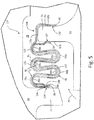
FIG. 5 is a cross-sectional view of another embodiment of the multi-ply split-ring seal with integral assembly clip, taken along line 5-5 ofFIG. 6 . -
FIG. 6 is a perspective view of an end portion of the seal with integral clip assembly ofFIG. 5 . -
FIG. 7 is a cross-sectional view of another embodiment of the multi-ply split-ring seal with integral clip assembly. -
FIG. 8 is a cross-sectional view of another embodiment of the multi-ply split-ring seal with integral clip assembly. -
FIG. 9 is a cross-sectional view of the multi-ply split-ring seal ofFIGS. 5 and6 with a heat shield. -
FIG. 10 is a cross-sectional view of the multi-ply split-ring seal ofFIG. 3 with a heat shield. - While the above-identified figures set forth embodiments of the present invention, other embodiments are also contemplated, as noted in the discussion. In all cases, this disclosure presents the invention by way of representation and not limitation. It should be understood that numerous other modifications and embodiments can be devised by those skilled in the art, which fall within the scope and spirit of the principles of the invention. The figures may not be drawn to scale, and applications and embodiments of the present invention may include features, steps and/or components not specifically shown in the drawings.
- A multi-ply seal with an integral clip and optional heat shield can facilitate assembly in a gas turbine engine and reduce or eliminate seal buckling due to thermal expansion. Although the present disclosure relates to seal assemblies used in gas turbine engines, it will be understood by one skilled in the art that use of the disclosed seal assemblies is not limited to gas turbine engines, but extends to multiple applications, particularly those that use W-type or related compressible seals to form a fluid barrier between two static components.
-
FIG. 1 is a quarter-sectional view of agas turbine engine 20 that includesfan section 22,compressor section 24,combustor section 26 andturbine section 28. Alternative engines might include an augmenter section (not shown) among other systems or features.Fan section 22 drives air along bypass flow path B whilecompressor section 24 draws air in along core flow path C where air is compressed and communicated tocombustor section 26. Incombustor section 26, air is mixed with fuel and ignited to generate a high pressure exhaust gas stream that expands throughturbine section 28 where energy is extracted and utilized to drivefan section 22 andcompressor section 24. - Although the disclosed non-limiting embodiment depicts a turbofan gas turbine engine, it should be understood that the concepts described herein are not limited to use with turbofans as the teachings may be applied to other types of turbine engines; for example a turbine engine including a three-spool architecture in which three spools concentrically rotate about a common axis and where a low spool enables a low pressure turbine to drive a fan via a gearbox, an intermediate spool that enables an intermediate pressure turbine to drive a first compressor of the compressor section, and a high spool that enables a high pressure turbine to drive a high pressure compressor of the compressor section.
- The
example engine 20 generally includeslow speed spool 30 andhigh speed spool 32 mounted for rotation about an engine central longitudinal axis A relative to an enginestatic structure 36 viaseveral bearing systems 38. It should be understood thatvarious bearing systems 38 at various locations may alternatively or additionally be provided. -
Low speed spool 30 generally includesinner shaft 40 that connectsfan 42 and low pressure (or first) compressor section 44 to low pressure (or first)turbine section 46.Inner shaft 40 drivesfan 42 through a speed change device, such as gearedarchitecture 48, to drivefan 42 at a lower speed thanlow speed spool 30. High-speed spool 32 includesouter shaft 50 that interconnects high pressure (or second)compressor section 52 and high pressure (or second)turbine section 54.Inner shaft 40 andouter shaft 50 are concentric and rotate viabearing systems 38 about engine central longitudinal axis A. - Combustor 56 is arranged between
high pressure compressor 52 andhigh pressure turbine 54. In one example,high pressure turbine 54 includes at least two stages to provide a double stagehigh pressure turbine 54. In another example,high pressure turbine 54 includes only a single stage. As used herein, a "high pressure" compressor or turbine experiences a higher pressure than a corresponding "low pressure" compressor or turbine. - The example
low pressure turbine 46 has a pressure ratio that is greater than about 5. The pressure ratio of the examplelow pressure turbine 46 is measured prior to an inlet oflow pressure turbine 46 as related to the pressure measured at the outlet oflow pressure turbine 46 prior to an exhaust nozzle. -
Mid-turbine frame 58 of enginestatic structure 36 is arranged generally betweenhigh pressure turbine 54 andlow pressure turbine 46.Mid-turbine frame 58 further supports bearingsystems 38 inturbine section 28 as well as setting airflow enteringlow pressure turbine 46. - The core airflow C is compressed by low pressure compressor 44 then by
high pressure compressor 52 mixed with fuel and ignited incombustor 56 to produce high speed exhaust gases that are then expanded throughhigh pressure turbine 54 andlow pressure turbine 46.Mid-turbine frame 58 includes airfoils/vanes 60, which are in the core airflow path and function as an inlet guide vane forlow pressure turbine 46. Utilizingvanes 60 ofmid-turbine frame 58 as inlet guide vanes forlow pressure turbine 46 decreases the length oflow pressure turbine 46 without increasing the axial length ofmid-turbine frame 58. Reducing or eliminating the number of vanes inlow pressure turbine 46 shortens the axial length ofturbine section 28. Thus, the compactness ofgas turbine engine 20 is increased and a higher power density may be achieved. - The disclosed
gas turbine engine 20 in one example is a high-bypass geared aircraft engine. In a further example,gas turbine engine 20 includes a bypass ratio greater than about six (6), with an example embodiment being greater than about ten (10). The example gearedarchitecture 48 is an epicyclical gear train, such as a planetary gear system, star gear system or other known gear system, with a gear reduction ratio of greater than about 2.3. - In one disclosed embodiment,
gas turbine engine 20 includes a bypass ratio greater than about ten (10:1) and the fan diameter is significantly larger than an outer diameter of low pressure compressor 44. It should be understood, however, that the above parameters are only exemplary of one embodiment of a gas turbine engine including a geared architecture and that the present disclosure is applicable to other gas turbine engines. -
FIG. 2 is a cross-sectional view of a compressor vane assembly of the gas turbine engine.FIG. 2 showscomponent 62,components seal assembly 66 positioned in a forward compartment betweencomponents components FIG. 2 ,component 62 can be a compressor statorring having vane 60,inner band 70, andouter band 72. Inner andouter bands vane 60.Outer band 72 can includeflange 73 extending radially outward fromouter band 72. As shown inFIG 2 ,component 64 can be a compressor support case having aflange 74 extending radially inward towardouter band 72.Seal assembly 66 can sealcooling cavity 75 betweencomponents core gas flow 76. During normal operation, a pressure differential acrossseal assembly 66 can be low, generally around 10-30 psi (69-207 kPa). During certain engine operating conditions, the pressure differential acrossseal assembly 66 can be as high as 150 psi (1034 kPa) Seal 68 can serve as a prime seal; whereasseal assembly 66 can serve as a redundant seal should seal 68 be compromised. AlthoughFIG. 2 illustrates use ofseal assembly 66 in a compressor section, it will be understood by one skilled in the art that the seal assemblies of the present disclosure can be used in multiple sections of the gas turbine engine as well as a variety of devices unrelated to gas turbine engines. -
FIGS. 3 and4 show one embodiment ofseal assembly 66.FIG. 3 is a cross-sectional view ofseal assembly 66.FIG. 4 is a side view ofseal assembly 66 inFIG. 3 looking aftward.Seal assembly 66 can be a multi-ply (e.g., two-ply) split-ring seal with an integral assembly clip.Seal assembly 66 can include split-ring seal 80 and split-ring seal 82. Split-ring seal 82 can be slidably received and nested in split-ring seal 80. Split-ring seal 80 can include circumferentially separated ends 84 and 86 (shown inFIG. 4 ) and laterally separatededges 88 and 90 (shown inFIG. 3 ). Likewise, split-ring 82 can include circumferentially separated ends 92 and 94 (shown inFIG. 4 ) and laterally separatededges 96 and 98 (shown inFIG. 3 ). Ends 84 and 86 can be separated from ends 92 and 94 by about 180 degrees to reduce leakage through the plies. A body portion of each of split-ring seal 80 and split-ring seal 82 can undulate to form a W-type or related seal having one or more turns 99a-d, capable of being compressed betweenfirst component 62 andsecond component 64. Eachturn 99a-d can substantially form an approximately 180 degree arc with a convex surface facing radially inward or outward toward axially extending portions ofcomponents - Having two or more split-rings (plies) can increase strength and rigidity of the
seal assembly 66 and allow for thermal expansion without buckling, as each split-ring seal ring seal ends ring seal 82 and at the interface ofends ring seal 80. However, leakage can be minimized by closely fitting split-ring seals FIG. 4 ). Likewise, ends 92 and 94 can be separated a distance (d2) along the circumference of split-ring seal 82 (shown inFIG. 4 ). The distances d1 and d2 can generally be equal to one another and can be an arc length corresponding approximately to a five degree angle. However, it will be understood by one skilled in the art, that d1 and d2 can be varied as necessary (increased or decreased) to accommodate thermal expansion of split-ring seals - Split-
ring seals integral clip portions first end 84 to second end 68 and fromthird end 92 tofourth end 94.Integral clip portions first component 62 to retainseal assembly 66 in position during assembly. Traditional W-seals without integral clip portions must be tack welded, glued, or otherwise fastened to one component to maintain position during assembly. With or without fastening, traditional W-seals, particularly single-ply full-ring W-seal have a tendency to be improperly pinched between components. Pinching can occur due to blind assembly (inability to visually inspect positioning of the W-seal during assembly) and delicate or flimsy construction of the W-seal, which allows the W-seal to hang downward outside of an ideal positioning for assembly.Integral clip portions seal assembly 66 in position and can also provide rigidity to sealassembly 66, thereby limiting the tendency of pinching due to downward hanging. The use of multiple plies or split-ring seals also increases rigidity for improved assembly.Integral clip portion 100 can have two bent portions including axially extendingportion 100a and radially extendingportions portion 100a, and bends 100d and 100e joiningaxial portion 100a withradial portions integral clip portion 102 can have axially extendingportion 102a and radially extendingportions portion 102a, and bends 102d and 102e joiningaxial portion 102a withradial portions Axial surfaces Bends Radially extending portions first side 110 offirst component 62.Radially extending portions second side 112 offirst component 62 oppositefirst side 110. The terms "radially extending" and "axial extending" are relative terms used merely for the sake of explaining illustrated embodiments, and are provided as reference to the orientation ofseal assembly 66 in the disclosed gas turbine engine. It will be understood by one skilled in the art that sealassembly 66 can be disposed in other directions, in which the terms "axially extending" and "radially extending" no longer apply as used in relation to the present embodiment.Radially extending portions portions integral clip portions seal assembly 66 ontofirst component 62. The tight biasing can provide additional rigidity to sealassembly 66 during assembly and operation. However, it will be understood by one skilled in the art that such tight biasing may not be necessary for all applications and can be modified as desired or as necessary. Additionally, althoughintegral clip portions integral clip portions - Split-
ring seal 80 can have sealinglobe 114adjacent edge 88.Sealing lobe 114 can have a convex curved surface extending laterally outward fromedge 88.Sealing lobe 114 can be compressed againstsecond component 64 upon assembly. The curved outwardly extending shape of sealinglobe 114 can allow increased pressure to be placed on a reduced contact area, thereby improving a seal betweenseal assembly 66 andsecond component 64 at the contact area, when assembled. Split-ring seal 82 can have sealinglobe 116 adjacent radially extendingportion 102b ofsecond clip portion 102.Sealing lobe 116 can have a convex curved surface extending toward and biased toward radially extendingportion 102c.Sealing lobe 116 can extend from a plane that is approximately perpendicular to a plane from which turns 99a-d extend, such that sealinglobe 116 can be compressed againstfirst side 110 offirst component 62 upon assembly. Like sealinglobe 114, the curved outwardly extending shape of sealinglobe 116 improves a seal betweenseal assembly 66 andfirst component 62. Split-ring seal 82 can additionally have sealinglobe 118adjacent edge 98.Sealing lobe 118 can have a convex curved surface extending laterally inward ofedge 98, such that sealinglobe 118 contactssecond side 112 offirst component 62 upon assembly.Sealing lobe 118 can be biased toward sealinglobe 116. Although disclosed as a "sealing" lobe, sealinglobe 118 can have a primary function of providing a tight fit tofirst component 62, while secondarily providing a redundant seal to sealinglobe 116. It will be understood by one skilled in the art that sealinglobe 118 can be modified or removed without adverse impact to the effectiveness ofseal assembly 66. - As shown in
FIG. 3 , split-ring seal 82 is closely nested in split-ring seal 80 and therefore split-ring seals ring seals ring seals ring seals -
FIGS. 5 and6 illustrate another embodiment of the multi-ply split-ring seal with integral assembly clip.FIG. 5 is a cross-sectional view ofseal assembly 124.FIG. 6 is a perspective view of an end portion ofseal assembly 124.Seal assembly 124 is similar to sealassembly 66, having split-ring seal 80 with circumferentially separated ends 84 and 86, laterally separatededges lobe 114; and split-ring seal 82 slidably nested in split-ring seal 80 and having circumferentially separated ends 92 and 94 and laterally separatededges seal assembly 66, split-ring seal 82 onseal assembly 124 does not includeintegral clip portion 102, while split-ring 80 does. Additionally, as shown inFIG. 5 , split-ring 82 can haveadditional turn 99e and split-ring 80 can havepartial turn 125.Partial turn 125 can have a convex curved surface directed radially outward. Split-ring seal 82 can include sealinglobe 127 adjacent to edge 98.Sealing lobe 127 can have a convex surface extending laterally outward fromedge 98 and can be compressed againstfirst side 110 offirst component 62 upon assembly to form a seal. Combined, sealinglobes cooling cavity 75 fromcore gas flow 76. - Split-
ring seal 80 can haveintegral clip portion 128adjacent edge 90.Integral clip portion 128 can have one bent portion, including axially extendingportion 128a, radially extendingportion 128b, and bend 128c joining axially extendingportion 128a and radially extendingportion 128b at a substantially 90 degree angle upon assembly.Radially extending portion 128b can beadjacent edge 90. As previously discussed, the terms "axially extending" and "radially extending" are relative terms used merely for the sake of explaining illustrated embodiments, and are provided as reference to the orientation ofseal assembly 128 in the disclosed gas turbine engine. It will be understood by one skilled in the art that seal assembly 128 can be disposed in other directions, in which the terms "axially extending" and "radially extending" no longer apply as used in relation to the present embodiment.Radially extending portion 128b can be biased toward sealinglobe 127 and can assembled in contact withsecond side 112 offirst component 62. Combined, sealinglobe 127 and radially extendingportion 128b can secureseal assembly 124 tofirst component 62. Split-ring seal 80 can additionally include sealinglobe 130adjacent edge 90 and biased toward sealinglobe 127.Sealing lobe 130 can have a convex curved surface extending laterally inward ofedge 90, which can thereby concentrate a pressure applied byintegral clip portion 128 onfirst component 62 upon assembly. Similar to sealinglobe 118, sealinglobe 130 can serve both to form a redundant seal tosecond sealing lobe 127 and to provide a tight fit tofirst component 62.Sealing lobe 130 is not necessary to secureseal assembly 124 tofirst component 62 and therefore can be modified or removed without substantially impacting the effectiveness ofseal assembly 124. -
Seal assembly 124 can include one or moreinsulating plenums 132 to reduce heat transfer betweencore gas flow 76 andcooling cavity 75. Split-ring seal 80 can be radially separated from split-ring seal 82 along at least a portion of the circumference to create one or moreinsulating plenums 132, thereby forming a gap or gaps. A distance (d3) between split-ring seals seal assembly 128 betweenedges edges larger plenums 132, which can serve as insulating layers between split-ring seals FIG. 5 . For instance, d3 can be smaller nearing turns 99a and 99e as well as sealinglobe 114. - To limit leakage across
seal assembly 128,plenums 132 can be closed at or nearlateral edges FIG. 5 , split-ring seal 82 can have sealinglobe 134adjacent edge 96.Sealing lobe 134 can match a shape of sealinglobe 114, having a convex curved surface extending laterally outward.Sealing lobe 114 can be compressed against a concaveinner surface 136 of sealinglobe 114 upon assembly to closeplenum 132 betweenedges ring seal 80 can contact split-ring seal 82 along the circumference atfirst turn 99a and laterally oppositesecond turn 99e.First turn 99a can be adjacentsecond component 64 andsecond turn 99e can be adjacentfirst component 62. First andsecond turns FIG. 5 , threeadditional turns 99b-d separate first andsecond turns ring seal 80 can contact split-ring seal 82 atadditional turns 99b-d or can be separated fromadditional turns 99b-d as shown inFIG. 5 to provide additional insulating capacity. -
FIG. 6 shows closure ofends ring seal 82 against the body of split-ring seal 80. As shown inFIG. 6 , split-rings end 92 to closeplenum 132. One or both of split-rings point 146, which correlates with a separation illustrated inFIG. 5 , to point 147 whereend 92 of split-ring seal 82 meets the body portion of split-ring seal 80. The gradual closing ofplenum 132 can generally extend 1-2 inches (25.4-50.8 mm) along the circumference of split-ring seal 80. Ends 84, 86, and 94, although not all shown, can close in the same or similar manner. Alternatively, ends 84, 86, 92, and 94 can be stepped inward to closeplenum 132. - Instead of having
air plenum 132,seal assembly 124 can have thermally insulatingmember 150 as shown inFIG. 7 . Insulatingmember 150 can be a ceramic or carbon fiber blanket or similar insulating member as known in the art.FIG. 7 is a cross-sectional view of modifiedseal assembly 124a.Seal assembly 124a can have an insulating member nested between split-ring seals member 150 can take the place ofplenum 132 or can more fully extend laterally between split-ring seals FIG. 7 . As shown inFIG. 7 , edge 88 of split-ring seal 80 can extend beyondedge 96 of split-ring seal 82 and can fold overedge 152 of insulatingmember 150 to secureinsulting member 150 in place and reduce leakage through insulatingmember 150. Alternatively, edge 96 can extend beyondedge 88 and fold over insulatingmember 150, provided the alternative does not interfere with proper sealing ofseal assembly 124a. Ends 84, 86, 92, and 94 ofseal assembly 124a can be stepped inward according toFIG. 6 and related disclosure, such that ends 84 and 86 of split-ring seal 80 havestep 146 to close against split-ring seal 82, and ends 92 and 94 are similarly stepped in to close against split-ring seal 80. - Incorporation of an insulating member is not limited to seal
assemblies FIG. 8 is a cross-sectional view of a modified embodiment of the multi-ply split ring seal assembly shown inFIG. 3 , showing modifiedseal assembly 66a with insulatingmember 150 disposed between split-ring seals FIG. 7 , edge 88 of split-ring seal 80 can extend beyondforward end 92 of split-ring seal and fold overedge 152 of insulatingmember 150 to secure insulatingmember 150 in place and reduce leakage through insulatingmember 150. On the laterally opposite edges 90 and 98,edge 98 of split-ring seal 82 can extend beyondedge 90 of split-ring seal 80 and fold overopposite end 154 of insulatingmember 150. Alternatively, edge 96 can fold over insulatingmember 150 and edge 90 can fold over insulatingmember 150, or any combination of the above that allows for proper sealing and securing ofseal assembly 66a. Ends 84, 86, 92, and 94 ofseal assembly 66a can be stepped inward according toFIG. 6 and related disclosure. -
FIGS. 9 and10 are cross-sectional views of the multi-ply split-ring seal assemblies (124 and 66) ofFIGS. 5 and3 , respectively, with the addition of a heat shield. Heat shields may find limited application in the compressor section of the gas turbine engine, but can provide added benefit in the turbine section where temperatures are elevated. As shown inFIG. 9 ,annular heat shield 160 can be nested inintegral clip portion 128, forming additionalintegral clip portion 162.Heat shield 160 can haveedge 164 positionedadjacent edge 90 of split-ring seal 80, and can have laterally oppositeedge 166 extending laterally outward formedge 88 of split-ring seal 80.Integral clip portion 162 can have axial extendingportion 162a and radially extendingportions portion 162a and such that radially extendingportion 162b isadjacent edge 164. As previously stated, the terms "axially extending" and "radially extending" are relative terms used merely for the sake of explaining illustrated embodiments.Heat shield 160 can have sealinglobe 170 adjacent radially extendingportion 162c.Sealing lobe 170 can have a convex curved surface extending laterally outward.Sealing lobe 170 can displace sealinglobe 127 of split-ring seal 82, such that sealinglobe 170 is compressed againstfirst side 110 offirst component 62 upon assembly and such that sealinglobe 127 is compressed into concaveinner surface 172 of sealinglobe 170. Likewise radially extendingportion 162b can displace radially extendingportion 128b of split-ring seal 80 away fromsecond side 112 offirst component 62 upon assembly.Sealing lobe 170 and radially extendingportion 162b can be tightly biased toward each other to form a tight fit overfirst component 62. Similar to previously disclosed embodiments and as shown inFIG. 9 ,heat shield 160 can have sealinglobe 174adjacent edge 164.Sealing lobe 174 can have a convex curved surface extending laterally inward fromedge 164, such that biasing pressure can be concentrated atedge 164.Sealing lobe 130 of split-ring seal can be fitted to innerconcave surface 176 of sealinglobe 174.Sealing lobe 174 can serve as a redundant seal for sealinglobe 172 and can provide a tight fit overfirst component 62. As disclosed for previous embodiments, sealinglobe 174 can be modified or removed without significantly impacting the effectiveness ofseal assembly 124. -
Heat shield 160 can havelobe 178adjacent edge 166.Lobe 178 can have a convex curved surface extending radially outward ofedge 166.Lobe 178 and axially extendingportion 179 can be biased toward turns 140 and 144 of split-ring seals wall 180 upon assembly.Wall 180 can be slanted to pressheat shield 160 radially inward during assembly to form a tight fit. Additionally, heat shield can havecurved section 183 to provide a closer fit to split-ring seal 82.Heat shield 160 can reduce thermal stresses on first and second spit-ring seals seal assembly 124. -
FIG. 10 shows seal assembly 66 withheat shield 184.Heat shield 184 can be structurally very similar toheat shield 160, havingedge 164;edge 166;integral clip portion 162, configured to clip ontofirst component 62; laterally extendingconvex sealing lobe 170 displacing and being compressed by sealinglobe 118 of split-ring seal 82 upon assembly; laterally extendingconvex sealing lobe 174adjacent edge 164 and configured to localize pressure againstfirst component 62; and radially extending sealinglobe 178 configured to engagewall 180. Unlike the embodiment disclosed inFIG. 9 ,integral clip portion 162 ofheat shield 184 can be nested inintegral clip portion 102 of split-ring seal 82, which can be nested inintegral clip portion 100 of split-ring seal 80, thereby forming a three-ply integral clip assembly. The three-ply integral clip assembly can improve strength of fit tofirst component 62 and rigidity ofseal assembly 66. Additionally, the incorporation ofheat shield 184 reduces thermal stress on split-ring seals and reduces heat transfer acrossseal assembly 66. - The disclosed multi-ply split ring seal assemblies with optional heat shield can facilitate assembly in gas turbine engines, reduce or eliminate seal buckling due to thermal expansion, reduce additional thermal stresses to the seal assembly, increase the lifetime of the seal assembly, and reduce heat transfer across the seal assembly. While the present disclosure relates to assembly in gas turbine engines, it will be understood by one skilled in the art that the disclosed seal assemblies can be adopted for use in multiple applications, particularly where traditional W-seals and related compressible seals are used.
- The following are non-exclusive descriptions of possible embodiments of the present invention.
- A seal assembly for a gas turbine engine includes first and second split-ring seal with the second split-ring seal being slidably received and nested in the first seal. The first split-ring seal includes circumferentially separated first and second ends, laterally separated first and second edges, a first sealing lobe adjacent the first edge, and a first integral clip portion adjacent the second edge. The first sealing lobe includes a curved surface extending laterally outward from the first edge. The second split-ring seal can include circumferentially separated third and fourth ends, and laterally separated third and fourth edges.
- The seal assembly of the preceding paragraph can optionally include, additionally and/or alternatively, any one or more of the following features, configurations and/or additional components:
- A further embodiment of the foregoing seal assembly, wherein the first clip portion can circumferentially extend from the first end to the second end.
- A further embodiment of the foregoing seal assembly, wherein at least a portion of each of the first and second seals can be substantially W-shaped.
- A further embodiment of the foregoing seal assembly, wherein the second split-ring seal can include a second sealing lobe adjacent the fourth edge. The second sealing lobe can be a curved surface extending laterally outward from the fourth edge.
- A further embodiment of the foregoing seal assembly, wherein the first split-ring seal further can include a third sealing lobe adjacent the second edge. The third sealing lobe can be a curved surface extending laterally inward from the second edge and the second sealing lobe can be biased toward the third sealing lobe.
- A further embodiment of the foregoing seal assembly can include a first component having a first side and second side located opposite the first side. The second sealing lobe can contact the first side and the third sealing lobe can contact the second side.
- A further embodiment of the foregoing seal assembly, wherein the first split-ring seal can be radially separated from the second split-ring seal along at least a portion of the circumference, and a distance between the first and second seal in at least a portion of the seal assembly between the first and second edges and third and fourth edges can be substantially equal to or greater than a thickness of the first split-ring seal.
- A further embodiment of the foregoing seal assembly, wherein the first split-ring seal can contact the second seal along the circumference at a first bend and at a laterally opposite second bend. The first and second bends can be separated by at least one additional bend.
- A further embodiment of the foregoing seal assembly, wherein the first, second, third and fourth ends can each comprise a step to substantially close one or more gaps between the first split-ring seal and the second split-ring seal.
- A further embodiment of the foregoing seal assembly can include insulating member. The insulating member can be nested between the first and second split-ring seals.
- A further embodiment of the foregoing seal assembly, wherein first edge of the first split-ring seal can extend beyond the third edge of the second split-ring seal and fold over an edge of the insulating member.
- A further embodiment of the foregoing seal assembly, wherein the second split-ring seal can include a second integral clip portion adjacent the fourth edge. The integral clip portion can include first and second radially extending portions, and an axial extending portion. The axial extending portion can separate the first and second radially extending portions, and the second radially extending portion can be adjacent the fourth edge. A fourth sealing lobe adjacent the first radial extending portion can include a curved surface extending toward and biased toward the second radially extending portion.
- A further embodiment of the foregoing seal assembly can include an annular heat shield nested in the second clip portion. The annular heat shield can include a fifth edge positioned adjacent the fourth edge of the second split-ring seal and a sixth edge extending laterally outward from the first edge of the first split-ring seal.
- A further embodiment of the foregoing seal assembly, wherein a portion of the first and second split-ring seals extending between the first and second edges and the first and second clip portions can have a substantially undulating shape.
- A further embodiment of the foregoing seal assembly can include a first component having a first side and second side located opposite the first side. The fourth sealing lobe can contact the first side and the first radially extending portion can contact the second side.
- A further embodiment of the foregoing seal assembly can include an annular heat shield nested in the first clip portion. The annular heat shield can include a fifth edge positioned adjacent the second edge of the first split-ring seal and a sixth edge extending laterally outward from the first edge of the first split-ring seal.
- A further embodiment of the foregoing seal assembly, wherein the second split-ring seal can include a second sealing lobe adjacent the fourth edge. The second sealing lobe can have a curved surface extending outward from the fourth edge. The heat shield can include a sixth sealing lobe having a curvature substantially matching the curved surface of the second sealing lobe and positioned in contact with the second sealing lobe.
- A method of sealing a cavity in a gas turbine engine includes clipping a portion of a multi-ply split-ring seal to a first component of a gas turbine engine and compressing a portion of each ply of the multi-ply seal between the first component and a second component of the gas turbine engine.
- The method of the preceding paragraph can optionally include, additionally and/or alternatively, any one or more of the following features, configurations and/or additional components:
- A further embodiment of the foregoing method can include clipping a heat shield to the first component of the gas turbine engine. The heat shield can be disposed between the first component and the seal.
- A further embodiment of the foregoing method providing an insulating layer between plies of the multi-ply seal.
- Any relative terms or terms of degree used herein, such as "substantially", "essentially", "generally", "approximately" and the like, should be interpreted in accordance with and subject to any applicable definitions or limits expressly stated herein. In all instances, any relative terms or terms of degree used herein should be interpreted to broadly encompass any relevant disclosed embodiments as well as such ranges or variations as would be understood by a person of ordinary skill in the art in view of the entirety of the present disclosure, such as to encompass ordinary manufacturing tolerance variations, incidental alignment variations, alignment or shape variations induced by thermal, rotational or vibrational operational conditions, and the like.
- While the invention has been described with reference to an exemplary embodiment(s), it will be understood by those skilled in the art that various changes may be made and equivalents may be substituted for elements thereof without departing from the scope of the invention. In addition, many modifications may be made to adapt a particular situation or material to the teachings of the invention without departing from the essential scope thereof. Therefore, it is intended that the invention not be limited to the particular embodiment(s) disclosed, but that the invention will include all embodiments falling within the scope of the appended claims.
Claims (15)
- A seal assembly (66; 124) for a gas turbine engine (20), the assembly comprising:a first split-ring seal (80) comprising:circumferentially separated first and second ends (84, 86);laterally separated first and second edges (88, 90);a first sealing lobe (114) adjacent the first edge (88), wherein the first sealing lobe (114) comprises a curved surface extending laterally outward from the first edge (88); anda first integral clip portion (100; 138) adjacent the second edge (90); anda second split-ring seal (82) slidably received and nested in the first seal (80), the second split-ring seal (82) comprising:circumferentially separated third and fourth ends (92, 94); andlaterally separated third and fourth edges (96, 98).
- The seal assembly of claim 1, wherein the first clip portion (100; 128) circumferentially extends from the first end (84) to the second end (86) .
- The seal assembly of claim 1 or 2, wherein the first split-ring seal (80) is radially separated from the second split-ring seal (82) along at least a portion of the circumference, and where a distance (d3) between the first and second seal (80, 82) in at least a portion of the seal assembly between the first and second edges (88, 90) and third and fourth edges (92, 94) is substantially equal to or greater than a thickness (ts) of the first split-ring seal (80), wherein, optionally, the first split-ring seal (80) contacts the second seal (82) along the circumference at a first bend (99a) and at a laterally opposite second bend (99e), the first and second bends (99a, 99e) being separated by at least one additional bend (99b-d).
- The seal assembly of any preceding claim further comprising:an insulating member (150), wherein the insulating member (150) is nested between the first and second split-ring seals (80, 82), wherein, optionally, first edge (88) of the first split-ring seal (80) extends beyond the third edge (96) of the second split-ring seal (82) and folds over an edge (152) of the insulating member (150).
- The seal assembly of any preceding claim, wherein the second split-ring seal (82) further comprises a second sealing lobe (127) adjacent the fourth edge (98), wherein the second sealing lobe (127) comprises a curved surface extending laterally outward from the fourth edge (98).
- The seal assembly of claim 5, wherein the first split-ring seal (80) further comprises a third sealing lobe (130) adjacent the second edge (90), wherein the third sealing lobe (130) comprises a curved surface extending laterally inward from the second edge (90), and wherein the second sealing lobe (127) is biased toward the third sealing lobe (130).
- The seal assembly of claim 6, further comprising:a first component (62) having a first side (110) and second side (112) located opposite the first side (110), wherein the second sealing lobe (127) contacts the first side (110) and the third sealing lobe (130) contacts the second side (112).
- The seal assembly of any of claims 1 to 4, wherein the second split-ring seal (82) further comprises:a second integral clip portion (102) adjacent the fourth edge (98), the integral clip portion (102) comprising:first and second radially extending portions (102b, 102b); andan axial extending portion (102a), wherein the axial extending portion (102a) separates the first and second radially extending portions (102b, 102c), and wherein the second radially extending portion (102c) is adjacent the fourth edge (98); anda fourth sealing lobe (116) adjacent the first radial extending portion (102b), wherein the fourth sealing lobe (116) comprises a curved surface extending toward and biased toward the second radially extending portion (102c).
- The seal assembly of claim 8, further comprising:an annular heat shield (184) nested in the second clip portion (102), the annular heat shield (184) comprising:a fifth edge (164) positioned adjacent the fourth edge (98) of the second split-ring seal (82); anda sixth edge (166) extending laterally outward from the first edge (88) of the first split-ring seal (80).
- The seal assembly of claim 8, further comprising:a first component (62) having a first side (110) and second side (112) located opposite the first side (110), wherein the fourth sealing lobe (116) contacts the first side (110) and the second radially extending portion (102c) contacts the second side (112).
- The seal assembly of any of claims 1 to 7, further comprising:an annular heat shield (160) nested in the first clip portion (128), the annular heat shield (160) comprising:a fifth edge (164) positioned adjacent the second edge (90) of the first split-ring seal (80); anda sixth edge (166) extending laterally outward from the first edge (88) of the first split-ring seal (80).
- The seal assembly of claim 11, wherein the second split-ring seal (82) further comprises a/the second sealing lobe (127) adjacent the fourth edge (98), wherein the second sealing lobe (127) comprises a/the curved surface extending outward from the fourth edge (98), and wherein the heat shield (160; 184) further comprises a sixth sealing lobe (170) comprising a curvature substantially matching the curved surface of the second sealing lobe (127) and positioned in contact with the second sealing lobe (127).
- A method of sealing a cavity (75) in a gas turbine engine (20), the method comprising:clipping a portion of a multi-ply split-ring seal (66; 124) to a first component (62) of a gas turbine engine (20); andcompressing a portion of each ply of the multi-ply seal (66; 124) between the first component (62) and a second component (64) of the gas turbine engine (20).
- The method of claim 13, further comprising:clipping a heat shield (160; 184) to the first component (62) of the gas turbine engine (20), wherein the heat shield (160; 184) is disposed between the first component (62) and the seal (66; 124).
- The method of claim 13 or 14, further comprising:providing an insulating layer (132; 150) between plies of the multi-ply seal (166; 124).
Applications Claiming Priority (1)
| Application Number | Priority Date | Filing Date | Title |
|---|---|---|---|
| US15/052,437 US10370992B2 (en) | 2016-02-24 | 2016-02-24 | Seal with integral assembly clip and method of sealing |
Publications (2)
| Publication Number | Publication Date |
|---|---|
| EP3211181A1 true EP3211181A1 (en) | 2017-08-30 |
| EP3211181B1 EP3211181B1 (en) | 2023-11-15 |
Family
ID=58185348
Family Applications (1)
| Application Number | Title | Priority Date | Filing Date |
|---|---|---|---|
| EP17157961.8A Active EP3211181B1 (en) | 2016-02-24 | 2017-02-24 | Seal with integral clip and method of sealing |
Country Status (2)
| Country | Link |
|---|---|
| US (2) | US10370992B2 (en) |
| EP (1) | EP3211181B1 (en) |
Cited By (6)
| Publication number | Priority date | Publication date | Assignee | Title |
|---|---|---|---|---|
| EP3309361A1 (en) * | 2016-10-12 | 2018-04-18 | United Technologies Corporation | Seal, corresponding engine section and gas turbine engine |
| FR3092869A1 (en) * | 2019-02-18 | 2020-08-21 | Safran Aircraft Engines | TURBOMACHINE DISTRIBUTORS WITH CONTACT INSERT |
| EP3252352B1 (en) * | 2016-05-31 | 2021-06-30 | Raytheon Technologies Corporation | Metal gasket bellows seal using dissimilar materials |
| FR3107725A1 (en) * | 2020-02-27 | 2021-09-03 | Safran Aircraft Engines | Assembly for an aircraft turbomachine stator, with reinforced sealing between an outer shell and a bladed stator ring surrounded by this shell |
| EP4345253A1 (en) * | 2022-09-30 | 2024-04-03 | RTX Corporation | Gas turbine engine including flow path flex seal with cooling air bifurcation |
| EP4345252A1 (en) * | 2022-09-30 | 2024-04-03 | RTX Corporation | Gas turbine engine including flow path flex seal and heat shield |
Families Citing this family (5)
| Publication number | Priority date | Publication date | Assignee | Title |
|---|---|---|---|---|
| US10260364B2 (en) | 2015-03-09 | 2019-04-16 | United Technologies Corporation | Sliding seal |
| US10370992B2 (en) * | 2016-02-24 | 2019-08-06 | United Technologies Corporation | Seal with integral assembly clip and method of sealing |
| KR102038112B1 (en) * | 2017-10-13 | 2019-10-29 | 두산중공업 주식회사 | Combustor and gas turbine including the same |
| US10927957B2 (en) * | 2018-08-22 | 2021-02-23 | Rolls-Royce North American Technologies Inc. | Deflection seal system |
| EP3789638A1 (en) * | 2019-09-05 | 2021-03-10 | Siemens Aktiengesellschaft | Seal for combustion apparatus |
Citations (5)
| Publication number | Priority date | Publication date | Assignee | Title |
|---|---|---|---|---|
| EP1521036A1 (en) * | 2003-10-02 | 2005-04-06 | Alstom Technology Ltd | Seal assembly |
| US20080053107A1 (en) * | 2006-08-03 | 2008-03-06 | Siemens Power Generation, Inc. | Slidable spring-loaded transition-to-turbine seal apparatus and heat-shielding system, comprising the seal, at transition/turbine junction of a gas turbine engine |
| US20150184528A1 (en) * | 2013-12-31 | 2015-07-02 | General Electric Company | System for sealing between combustors and turbine of gas turbine engine |
| EP2930312A2 (en) * | 2014-04-11 | 2015-10-14 | United Technologies Corporation | Cooled finger seal |
| EP2949874A1 (en) * | 2014-05-30 | 2015-12-02 | United Technologies Corporation | Dual walled seal assembly |
Family Cites Families (33)
| Publication number | Priority date | Publication date | Assignee | Title |
|---|---|---|---|---|
| US3012802A (en) * | 1958-12-04 | 1961-12-12 | Associated Spring Corp | High temperature seal |
| US4199151A (en) * | 1978-08-14 | 1980-04-22 | General Electric Company | Method and apparatus for retaining seals |
| DE2948686C2 (en) | 1979-12-04 | 1983-09-29 | Gestra Kondensatableiter Gmbh & Co Kg, 2800 Bremen | Bimetal controlled condensate drain |
| US4759555A (en) * | 1985-07-25 | 1988-07-26 | Eg&G Pressure Science, Inc. | Split ring seal with slip joint |
| US4602795A (en) * | 1985-12-06 | 1986-07-29 | United Technologies Corporation | Thermally expansive slip joint for formed sheet metal seals |
| US5125796A (en) * | 1991-05-14 | 1992-06-30 | General Electric Company | Transition piece seal spring for a gas turbine |
| US5249814A (en) * | 1992-01-31 | 1993-10-05 | Eg&G Pressure Science, Inc. | Multi-ply sealing rings and methods for manufacturing same |
| US5630593A (en) * | 1994-09-12 | 1997-05-20 | Eg&G Pressure Science, Inc. | Pressure-energized sealing rings |
| US6076835A (en) | 1997-05-21 | 2000-06-20 | Allison Advanced Development Company | Interstage van seal apparatus |
| US6199871B1 (en) * | 1998-09-02 | 2001-03-13 | General Electric Company | High excursion ring seal |
| US6237921B1 (en) | 1998-09-02 | 2001-05-29 | General Electric Company | Nested bridge seal |
| US6352267B1 (en) | 1999-03-12 | 2002-03-05 | John E. Rode | Adjustaby sizeable ring seal |
| US6299178B1 (en) * | 1999-04-29 | 2001-10-09 | Jetseal, Inc. | Resilient seals with inflection regions and/or ply deformations |
| US6968615B1 (en) * | 2000-10-24 | 2005-11-29 | The Advanced Products Company | High temperature metallic seal |
| US6609375B2 (en) | 2001-09-14 | 2003-08-26 | Honeywell International Inc. | Air cooling system for electric assisted turbocharger |
| JP4577813B2 (en) * | 2003-08-20 | 2010-11-10 | イーグル・エンジニアリング・エアロスペース株式会社 | Sealing device |
| US7178340B2 (en) * | 2003-09-24 | 2007-02-20 | Power Systems Mfg., Llc | Transition duct honeycomb seal |
| US7238003B2 (en) * | 2004-08-24 | 2007-07-03 | Pratt & Whitney Canada Corp. | Vane attachment arrangement |
| US7172388B2 (en) * | 2004-08-24 | 2007-02-06 | Pratt & Whitney Canada Corp. | Multi-point seal |
| WO2008114185A1 (en) | 2007-03-16 | 2008-09-25 | Csir | A wax actuator and a method of actuating by means of a wax actuator |
| US8016297B2 (en) * | 2008-03-27 | 2011-09-13 | United Technologies Corporation | Gas turbine engine seals and engines incorporating such seals |
| US9879555B2 (en) * | 2011-05-20 | 2018-01-30 | Siemens Energy, Inc. | Turbine combustion system transition seals |
| WO2015002673A2 (en) * | 2013-02-20 | 2015-01-08 | United Technologies Corporation | Gas turbine engine seal assembly |
| EP2961939B1 (en) | 2013-02-27 | 2019-04-10 | United Technologies Corporation | Assembly for sealing a gap between components of a turbine engine |
| US20140290269A1 (en) | 2013-03-08 | 2014-10-02 | United Technologies Corporation | Duct blocker seal assembly for a gas turbine engine |
| US10145308B2 (en) * | 2014-02-10 | 2018-12-04 | United Technologies Corporation | Gas turbine engine ring seal |
| US10088049B2 (en) * | 2014-05-06 | 2018-10-02 | United Technologies Corporation | Thermally protected seal assembly |
| US10273821B2 (en) * | 2015-09-10 | 2019-04-30 | General Electric Company | Advanced stationary sealing cooled cross-section for axial retention of ceramic matrix composite shrouds |
| US10370992B2 (en) * | 2016-02-24 | 2019-08-06 | United Technologies Corporation | Seal with integral assembly clip and method of sealing |
| US9708922B1 (en) * | 2016-05-23 | 2017-07-18 | United Technologies Corporation | Seal ring for gas turbine engines |
| US10487943B2 (en) * | 2016-07-12 | 2019-11-26 | United Technologies Corporation | Multi-ply seal ring |
| US10385717B2 (en) * | 2016-10-12 | 2019-08-20 | United Technologies Corporation | Multi-ply seal |
| US10450883B2 (en) * | 2016-10-31 | 2019-10-22 | United Technologies Corporation | W-seal shield for interrupted cavity |
-
2016
- 2016-02-24 US US15/052,437 patent/US10370992B2/en active Active
-
2017
- 2017-02-24 EP EP17157961.8A patent/EP3211181B1/en active Active
-
2019
- 2019-06-26 US US16/453,405 patent/US11459904B2/en active Active
Patent Citations (5)
| Publication number | Priority date | Publication date | Assignee | Title |
|---|---|---|---|---|
| EP1521036A1 (en) * | 2003-10-02 | 2005-04-06 | Alstom Technology Ltd | Seal assembly |
| US20080053107A1 (en) * | 2006-08-03 | 2008-03-06 | Siemens Power Generation, Inc. | Slidable spring-loaded transition-to-turbine seal apparatus and heat-shielding system, comprising the seal, at transition/turbine junction of a gas turbine engine |
| US20150184528A1 (en) * | 2013-12-31 | 2015-07-02 | General Electric Company | System for sealing between combustors and turbine of gas turbine engine |
| EP2930312A2 (en) * | 2014-04-11 | 2015-10-14 | United Technologies Corporation | Cooled finger seal |
| EP2949874A1 (en) * | 2014-05-30 | 2015-12-02 | United Technologies Corporation | Dual walled seal assembly |
Cited By (8)
| Publication number | Priority date | Publication date | Assignee | Title |
|---|---|---|---|---|
| EP3252352B1 (en) * | 2016-05-31 | 2021-06-30 | Raytheon Technologies Corporation | Metal gasket bellows seal using dissimilar materials |
| EP3309361A1 (en) * | 2016-10-12 | 2018-04-18 | United Technologies Corporation | Seal, corresponding engine section and gas turbine engine |
| US10385717B2 (en) | 2016-10-12 | 2019-08-20 | United Technologies Corporation | Multi-ply seal |
| FR3092869A1 (en) * | 2019-02-18 | 2020-08-21 | Safran Aircraft Engines | TURBOMACHINE DISTRIBUTORS WITH CONTACT INSERT |
| FR3107725A1 (en) * | 2020-02-27 | 2021-09-03 | Safran Aircraft Engines | Assembly for an aircraft turbomachine stator, with reinforced sealing between an outer shell and a bladed stator ring surrounded by this shell |
| EP4345253A1 (en) * | 2022-09-30 | 2024-04-03 | RTX Corporation | Gas turbine engine including flow path flex seal with cooling air bifurcation |
| EP4345252A1 (en) * | 2022-09-30 | 2024-04-03 | RTX Corporation | Gas turbine engine including flow path flex seal and heat shield |
| US11965427B1 (en) | 2022-09-30 | 2024-04-23 | Rtx Corporation | Gas turbine engine including flow path flex seal and heat shield |
Also Published As
| Publication number | Publication date |
|---|---|
| US20200032667A1 (en) | 2020-01-30 |
| US20170241280A1 (en) | 2017-08-24 |
| US11459904B2 (en) | 2022-10-04 |
| US10370992B2 (en) | 2019-08-06 |
| EP3211181B1 (en) | 2023-11-15 |
Similar Documents
| Publication | Publication Date | Title |
|---|---|---|
| US11459904B2 (en) | Seal with integral assembly clip and method of sealing | |
| JP4781017B2 (en) | Turbine vane color seal | |
| JP5572178B2 (en) | Vane structure and low pressure turbine for gas turbine engine | |
| EP3284910B1 (en) | Combustor finger seal | |
| US10655489B2 (en) | Systems and methods for assembling flow path components | |
| EP3249170A1 (en) | Seal assembly with seal rings for gas turbine engines | |
| EP3249168B1 (en) | Sealing and retention system | |
| US10273821B2 (en) | Advanced stationary sealing cooled cross-section for axial retention of ceramic matrix composite shrouds | |
| US10865652B2 (en) | Method and device for piston seal anti-rotation | |
| US9945257B2 (en) | Ceramic matrix composite ring shroud retention methods-CMC pin-head | |
| US10794204B2 (en) | Advanced stationary sealing concepts for axial retention of ceramic matrix composite shrouds | |
| EP3252275B1 (en) | Joined two ply w seal | |
| US11608752B2 (en) | Sealing apparatus for an axial flow turbomachine | |
| EP3719359B1 (en) | Extended pilot ring seal arrangement for installation damage prevention | |
| US11111794B2 (en) | Feather seals with leakage metering | |
| EP3309361B1 (en) | Seal, corresponding engine section and gas turbine engine | |
| US20150118042A1 (en) | Method and system for providing sealing in gas turbines | |
| EP3252352B1 (en) | Metal gasket bellows seal using dissimilar materials |
Legal Events
| Date | Code | Title | Description |
|---|---|---|---|
| PUAI | Public reference made under article 153(3) epc to a published international application that has entered the european phase |
Free format text: ORIGINAL CODE: 0009012 |
|
| STAA | Information on the status of an ep patent application or granted ep patent |
Free format text: STATUS: THE APPLICATION HAS BEEN PUBLISHED |
|
| AK | Designated contracting states |
Kind code of ref document: A1 Designated state(s): AL AT BE BG CH CY CZ DE DK EE ES FI FR GB GR HR HU IE IS IT LI LT LU LV MC MK MT NL NO PL PT RO RS SE SI SK SM TR |
|
| AX | Request for extension of the european patent |
Extension state: BA ME |
|
| STAA | Information on the status of an ep patent application or granted ep patent |
Free format text: STATUS: REQUEST FOR EXAMINATION WAS MADE |
|
| 17P | Request for examination filed |
Effective date: 20180228 |
|
| RBV | Designated contracting states (corrected) |
Designated state(s): AL AT BE BG CH CY CZ DE DK EE ES FI FR GB GR HR HU IE IS IT LI LT LU LV MC MK MT NL NO PL PT RO RS SE SI SK SM TR |
|
| STAA | Information on the status of an ep patent application or granted ep patent |
Free format text: STATUS: EXAMINATION IS IN PROGRESS |
|
| STAA | Information on the status of an ep patent application or granted ep patent |
Free format text: STATUS: EXAMINATION IS IN PROGRESS |
|
| 17Q | First examination report despatched |
Effective date: 20201019 |
|
| STAA | Information on the status of an ep patent application or granted ep patent |
Free format text: STATUS: EXAMINATION IS IN PROGRESS |
|
| RAP1 | Party data changed (applicant data changed or rights of an application transferred) |
Owner name: RAYTHEON TECHNOLOGIES CORPORATION |
|
| GRAP | Despatch of communication of intention to grant a patent |
Free format text: ORIGINAL CODE: EPIDOSNIGR1 |
|
| STAA | Information on the status of an ep patent application or granted ep patent |
Free format text: STATUS: GRANT OF PATENT IS INTENDED |
|
| INTG | Intention to grant announced |
Effective date: 20230606 |
|
| GRAS | Grant fee paid |
Free format text: ORIGINAL CODE: EPIDOSNIGR3 |
|
| GRAA | (expected) grant |
Free format text: ORIGINAL CODE: 0009210 |
|
| STAA | Information on the status of an ep patent application or granted ep patent |
Free format text: STATUS: THE PATENT HAS BEEN GRANTED |
|
| RAP3 | Party data changed (applicant data changed or rights of an application transferred) |
Owner name: RTX CORPORATION |
|
| AK | Designated contracting states |
Kind code of ref document: B1 Designated state(s): AL AT BE BG CH CY CZ DE DK EE ES FI FR GB GR HR HU IE IS IT LI LT LU LV MC MK MT NL NO PL PT RO RS SE SI SK SM TR |
|
| REG | Reference to a national code |
Ref country code: CH Ref legal event code: EP Ref country code: GB Ref legal event code: FG4D |
|
| REG | Reference to a national code |
Ref country code: DE Ref legal event code: R096 Ref document number: 602017076462 Country of ref document: DE |
|
| REG | Reference to a national code |
Ref country code: IE Ref legal event code: FG4D |
|
| REG | Reference to a national code |
Ref country code: LT Ref legal event code: MG9D |
|
| REG | Reference to a national code |
Ref country code: NL Ref legal event code: MP Effective date: 20231115 |
|
| PG25 | Lapsed in a contracting state [announced via postgrant information from national office to epo] |
Ref country code: GR Free format text: LAPSE BECAUSE OF FAILURE TO SUBMIT A TRANSLATION OF THE DESCRIPTION OR TO PAY THE FEE WITHIN THE PRESCRIBED TIME-LIMIT Effective date: 20240216 |
|
| PG25 | Lapsed in a contracting state [announced via postgrant information from national office to epo] |
Ref country code: IS Free format text: LAPSE BECAUSE OF FAILURE TO SUBMIT A TRANSLATION OF THE DESCRIPTION OR TO PAY THE FEE WITHIN THE PRESCRIBED TIME-LIMIT Effective date: 20240315 |
|
| PG25 | Lapsed in a contracting state [announced via postgrant information from national office to epo] |
Ref country code: LT Free format text: LAPSE BECAUSE OF FAILURE TO SUBMIT A TRANSLATION OF THE DESCRIPTION OR TO PAY THE FEE WITHIN THE PRESCRIBED TIME-LIMIT Effective date: 20231115 |
|
| REG | Reference to a national code |
Ref country code: AT Ref legal event code: MK05 Ref document number: 1631963 Country of ref document: AT Kind code of ref document: T Effective date: 20231115 |
|
| PG25 | Lapsed in a contracting state [announced via postgrant information from national office to epo] |
Ref country code: NL Free format text: LAPSE BECAUSE OF FAILURE TO SUBMIT A TRANSLATION OF THE DESCRIPTION OR TO PAY THE FEE WITHIN THE PRESCRIBED TIME-LIMIT Effective date: 20231115 |
|
| PG25 | Lapsed in a contracting state [announced via postgrant information from national office to epo] |
Ref country code: AT Free format text: LAPSE BECAUSE OF FAILURE TO SUBMIT A TRANSLATION OF THE DESCRIPTION OR TO PAY THE FEE WITHIN THE PRESCRIBED TIME-LIMIT Effective date: 20231115 |
|
| PG25 | Lapsed in a contracting state [announced via postgrant information from national office to epo] |
Ref country code: ES Free format text: LAPSE BECAUSE OF FAILURE TO SUBMIT A TRANSLATION OF THE DESCRIPTION OR TO PAY THE FEE WITHIN THE PRESCRIBED TIME-LIMIT Effective date: 20231115 |
|
| PG25 | Lapsed in a contracting state [announced via postgrant information from national office to epo] |
Ref country code: NL Free format text: LAPSE BECAUSE OF FAILURE TO SUBMIT A TRANSLATION OF THE DESCRIPTION OR TO PAY THE FEE WITHIN THE PRESCRIBED TIME-LIMIT Effective date: 20231115 Ref country code: LT Free format text: LAPSE BECAUSE OF FAILURE TO SUBMIT A TRANSLATION OF THE DESCRIPTION OR TO PAY THE FEE WITHIN THE PRESCRIBED TIME-LIMIT Effective date: 20231115 Ref country code: IS Free format text: LAPSE BECAUSE OF FAILURE TO SUBMIT A TRANSLATION OF THE DESCRIPTION OR TO PAY THE FEE WITHIN THE PRESCRIBED TIME-LIMIT Effective date: 20240315 Ref country code: GR Free format text: LAPSE BECAUSE OF FAILURE TO SUBMIT A TRANSLATION OF THE DESCRIPTION OR TO PAY THE FEE WITHIN THE PRESCRIBED TIME-LIMIT Effective date: 20240216 Ref country code: ES Free format text: LAPSE BECAUSE OF FAILURE TO SUBMIT A TRANSLATION OF THE DESCRIPTION OR TO PAY THE FEE WITHIN THE PRESCRIBED TIME-LIMIT Effective date: 20231115 Ref country code: BG Free format text: LAPSE BECAUSE OF FAILURE TO SUBMIT A TRANSLATION OF THE DESCRIPTION OR TO PAY THE FEE WITHIN THE PRESCRIBED TIME-LIMIT Effective date: 20240215 Ref country code: AT Free format text: LAPSE BECAUSE OF FAILURE TO SUBMIT A TRANSLATION OF THE DESCRIPTION OR TO PAY THE FEE WITHIN THE PRESCRIBED TIME-LIMIT Effective date: 20231115 Ref country code: PT Free format text: LAPSE BECAUSE OF FAILURE TO SUBMIT A TRANSLATION OF THE DESCRIPTION OR TO PAY THE FEE WITHIN THE PRESCRIBED TIME-LIMIT Effective date: 20240315 |
|
| PGFP | Annual fee paid to national office [announced via postgrant information from national office to epo] |
Ref country code: DE Payment date: 20240123 Year of fee payment: 8 Ref country code: GB Payment date: 20240123 Year of fee payment: 8 |
|
| PG25 | Lapsed in a contracting state [announced via postgrant information from national office to epo] |
Ref country code: SE Free format text: LAPSE BECAUSE OF FAILURE TO SUBMIT A TRANSLATION OF THE DESCRIPTION OR TO PAY THE FEE WITHIN THE PRESCRIBED TIME-LIMIT Effective date: 20231115 Ref country code: RS Free format text: LAPSE BECAUSE OF FAILURE TO SUBMIT A TRANSLATION OF THE DESCRIPTION OR TO PAY THE FEE WITHIN THE PRESCRIBED TIME-LIMIT Effective date: 20231115 Ref country code: PL Free format text: LAPSE BECAUSE OF FAILURE TO SUBMIT A TRANSLATION OF THE DESCRIPTION OR TO PAY THE FEE WITHIN THE PRESCRIBED TIME-LIMIT Effective date: 20231115 Ref country code: NO Free format text: LAPSE BECAUSE OF FAILURE TO SUBMIT A TRANSLATION OF THE DESCRIPTION OR TO PAY THE FEE WITHIN THE PRESCRIBED TIME-LIMIT Effective date: 20240215 Ref country code: LV Free format text: LAPSE BECAUSE OF FAILURE TO SUBMIT A TRANSLATION OF THE DESCRIPTION OR TO PAY THE FEE WITHIN THE PRESCRIBED TIME-LIMIT Effective date: 20231115 Ref country code: HR Free format text: LAPSE BECAUSE OF FAILURE TO SUBMIT A TRANSLATION OF THE DESCRIPTION OR TO PAY THE FEE WITHIN THE PRESCRIBED TIME-LIMIT Effective date: 20231115 |
|
| PGFP | Annual fee paid to national office [announced via postgrant information from national office to epo] |
Ref country code: FR Payment date: 20240123 Year of fee payment: 8 |
|
| PG25 | Lapsed in a contracting state [announced via postgrant information from national office to epo] |
Ref country code: DK Free format text: LAPSE BECAUSE OF FAILURE TO SUBMIT A TRANSLATION OF THE DESCRIPTION OR TO PAY THE FEE WITHIN THE PRESCRIBED TIME-LIMIT Effective date: 20231115 |
|
| PG25 | Lapsed in a contracting state [announced via postgrant information from national office to epo] |
Ref country code: CZ Free format text: LAPSE BECAUSE OF FAILURE TO SUBMIT A TRANSLATION OF THE DESCRIPTION OR TO PAY THE FEE WITHIN THE PRESCRIBED TIME-LIMIT Effective date: 20231115 |
|
| PG25 | Lapsed in a contracting state [announced via postgrant information from national office to epo] |
Ref country code: SK Free format text: LAPSE BECAUSE OF FAILURE TO SUBMIT A TRANSLATION OF THE DESCRIPTION OR TO PAY THE FEE WITHIN THE PRESCRIBED TIME-LIMIT Effective date: 20231115 |
|
| PG25 | Lapsed in a contracting state [announced via postgrant information from national office to epo] |
Ref country code: SM Free format text: LAPSE BECAUSE OF FAILURE TO SUBMIT A TRANSLATION OF THE DESCRIPTION OR TO PAY THE FEE WITHIN THE PRESCRIBED TIME-LIMIT Effective date: 20231115 Ref country code: SK Free format text: LAPSE BECAUSE OF FAILURE TO SUBMIT A TRANSLATION OF THE DESCRIPTION OR TO PAY THE FEE WITHIN THE PRESCRIBED TIME-LIMIT Effective date: 20231115 Ref country code: RO Free format text: LAPSE BECAUSE OF FAILURE TO SUBMIT A TRANSLATION OF THE DESCRIPTION OR TO PAY THE FEE WITHIN THE PRESCRIBED TIME-LIMIT Effective date: 20231115 Ref country code: IT Free format text: LAPSE BECAUSE OF FAILURE TO SUBMIT A TRANSLATION OF THE DESCRIPTION OR TO PAY THE FEE WITHIN THE PRESCRIBED TIME-LIMIT Effective date: 20231115 Ref country code: EE Free format text: LAPSE BECAUSE OF FAILURE TO SUBMIT A TRANSLATION OF THE DESCRIPTION OR TO PAY THE FEE WITHIN THE PRESCRIBED TIME-LIMIT Effective date: 20231115 Ref country code: DK Free format text: LAPSE BECAUSE OF FAILURE TO SUBMIT A TRANSLATION OF THE DESCRIPTION OR TO PAY THE FEE WITHIN THE PRESCRIBED TIME-LIMIT Effective date: 20231115 Ref country code: CZ Free format text: LAPSE BECAUSE OF FAILURE TO SUBMIT A TRANSLATION OF THE DESCRIPTION OR TO PAY THE FEE WITHIN THE PRESCRIBED TIME-LIMIT Effective date: 20231115 |