EP3211180B1 - Turbine bucket lockwire anti-rotation device for gas turbine engine - Google Patents
Turbine bucket lockwire anti-rotation device for gas turbine engine Download PDFInfo
- Publication number
- EP3211180B1 EP3211180B1 EP17157723.2A EP17157723A EP3211180B1 EP 3211180 B1 EP3211180 B1 EP 3211180B1 EP 17157723 A EP17157723 A EP 17157723A EP 3211180 B1 EP3211180 B1 EP 3211180B1
- Authority
- EP
- European Patent Office
- Prior art keywords
- lockwire
- locking key
- central portion
- gas turbine
- turbine engine
- Prior art date
- Legal status (The legal status is an assumption and is not a legal conclusion. Google has not performed a legal analysis and makes no representation as to the accuracy of the status listed.)
- Active
Links
Images





Classifications
-
- F—MECHANICAL ENGINEERING; LIGHTING; HEATING; WEAPONS; BLASTING
- F01—MACHINES OR ENGINES IN GENERAL; ENGINE PLANTS IN GENERAL; STEAM ENGINES
- F01D—NON-POSITIVE DISPLACEMENT MACHINES OR ENGINES, e.g. STEAM TURBINES
- F01D5/00—Blades; Blade-carrying members; Heating, heat-insulating, cooling or antivibration means on the blades or the members
- F01D5/30—Fixing blades to rotors; Blade roots ; Blade spacers
- F01D5/3007—Fixing blades to rotors; Blade roots ; Blade spacers of axial insertion type
-
- F—MECHANICAL ENGINEERING; LIGHTING; HEATING; WEAPONS; BLASTING
- F01—MACHINES OR ENGINES IN GENERAL; ENGINE PLANTS IN GENERAL; STEAM ENGINES
- F01D—NON-POSITIVE DISPLACEMENT MACHINES OR ENGINES, e.g. STEAM TURBINES
- F01D25/00—Component parts, details, or accessories, not provided for in, or of interest apart from, other groups
- F01D25/04—Antivibration arrangements
-
- F—MECHANICAL ENGINEERING; LIGHTING; HEATING; WEAPONS; BLASTING
- F01—MACHINES OR ENGINES IN GENERAL; ENGINE PLANTS IN GENERAL; STEAM ENGINES
- F01D—NON-POSITIVE DISPLACEMENT MACHINES OR ENGINES, e.g. STEAM TURBINES
- F01D5/00—Blades; Blade-carrying members; Heating, heat-insulating, cooling or antivibration means on the blades or the members
- F01D5/30—Fixing blades to rotors; Blade roots ; Blade spacers
- F01D5/32—Locking, e.g. by final locking blades or keys
-
- F—MECHANICAL ENGINEERING; LIGHTING; HEATING; WEAPONS; BLASTING
- F01—MACHINES OR ENGINES IN GENERAL; ENGINE PLANTS IN GENERAL; STEAM ENGINES
- F01D—NON-POSITIVE DISPLACEMENT MACHINES OR ENGINES, e.g. STEAM TURBINES
- F01D5/00—Blades; Blade-carrying members; Heating, heat-insulating, cooling or antivibration means on the blades or the members
- F01D5/30—Fixing blades to rotors; Blade roots ; Blade spacers
- F01D5/32—Locking, e.g. by final locking blades or keys
- F01D5/323—Locking of axial insertion type blades by means of a key or the like parallel to the axis of the rotor
-
- F—MECHANICAL ENGINEERING; LIGHTING; HEATING; WEAPONS; BLASTING
- F01—MACHINES OR ENGINES IN GENERAL; ENGINE PLANTS IN GENERAL; STEAM ENGINES
- F01D—NON-POSITIVE DISPLACEMENT MACHINES OR ENGINES, e.g. STEAM TURBINES
- F01D5/00—Blades; Blade-carrying members; Heating, heat-insulating, cooling or antivibration means on the blades or the members
- F01D5/30—Fixing blades to rotors; Blade roots ; Blade spacers
- F01D5/32—Locking, e.g. by final locking blades or keys
- F01D5/326—Locking of axial insertion type blades by other means
-
- F—MECHANICAL ENGINEERING; LIGHTING; HEATING; WEAPONS; BLASTING
- F01—MACHINES OR ENGINES IN GENERAL; ENGINE PLANTS IN GENERAL; STEAM ENGINES
- F01D—NON-POSITIVE DISPLACEMENT MACHINES OR ENGINES, e.g. STEAM TURBINES
- F01D5/00—Blades; Blade-carrying members; Heating, heat-insulating, cooling or antivibration means on the blades or the members
- F01D5/12—Blades
-
- F—MECHANICAL ENGINEERING; LIGHTING; HEATING; WEAPONS; BLASTING
- F05—INDEXING SCHEMES RELATING TO ENGINES OR PUMPS IN VARIOUS SUBCLASSES OF CLASSES F01-F04
- F05D—INDEXING SCHEME FOR ASPECTS RELATING TO NON-POSITIVE-DISPLACEMENT MACHINES OR ENGINES, GAS-TURBINES OR JET-PROPULSION PLANTS
- F05D2220/00—Application
- F05D2220/30—Application in turbines
- F05D2220/32—Application in turbines in gas turbines
-
- F—MECHANICAL ENGINEERING; LIGHTING; HEATING; WEAPONS; BLASTING
- F05—INDEXING SCHEMES RELATING TO ENGINES OR PUMPS IN VARIOUS SUBCLASSES OF CLASSES F01-F04
- F05D—INDEXING SCHEME FOR ASPECTS RELATING TO NON-POSITIVE-DISPLACEMENT MACHINES OR ENGINES, GAS-TURBINES OR JET-PROPULSION PLANTS
- F05D2230/00—Manufacture
- F05D2230/60—Assembly methods
-
- F—MECHANICAL ENGINEERING; LIGHTING; HEATING; WEAPONS; BLASTING
- F05—INDEXING SCHEMES RELATING TO ENGINES OR PUMPS IN VARIOUS SUBCLASSES OF CLASSES F01-F04
- F05D—INDEXING SCHEME FOR ASPECTS RELATING TO NON-POSITIVE-DISPLACEMENT MACHINES OR ENGINES, GAS-TURBINES OR JET-PROPULSION PLANTS
- F05D2260/00—Function
- F05D2260/30—Retaining components in desired mutual position
-
- F—MECHANICAL ENGINEERING; LIGHTING; HEATING; WEAPONS; BLASTING
- F05—INDEXING SCHEMES RELATING TO ENGINES OR PUMPS IN VARIOUS SUBCLASSES OF CLASSES F01-F04
- F05D—INDEXING SCHEME FOR ASPECTS RELATING TO NON-POSITIVE-DISPLACEMENT MACHINES OR ENGINES, GAS-TURBINES OR JET-PROPULSION PLANTS
- F05D2260/00—Function
- F05D2260/30—Retaining components in desired mutual position
- F05D2260/36—Retaining components in desired mutual position by a form fit connection, e.g. by interlocking
-
- Y—GENERAL TAGGING OF NEW TECHNOLOGICAL DEVELOPMENTS; GENERAL TAGGING OF CROSS-SECTIONAL TECHNOLOGIES SPANNING OVER SEVERAL SECTIONS OF THE IPC; TECHNICAL SUBJECTS COVERED BY FORMER USPC CROSS-REFERENCE ART COLLECTIONS [XRACs] AND DIGESTS
- Y02—TECHNOLOGIES OR APPLICATIONS FOR MITIGATION OR ADAPTATION AGAINST CLIMATE CHANGE
- Y02T—CLIMATE CHANGE MITIGATION TECHNOLOGIES RELATED TO TRANSPORTATION
- Y02T50/00—Aeronautics or air transport
- Y02T50/60—Efficient propulsion technologies, e.g. for aircraft
Definitions
- the present application pertains generally, but not by way of limitation, to gas turbine engines. More particularly, the present application is directed to devices and systems for axially retaining blades in slots of rotor disks or wheels.
- Gas turbine engines operate by passing a volume of gases through a series of compressors and turbines in order to produce rotational shaft power.
- High energy gases rotate a high pressure turbine to generate the shaft power.
- the shaft power drives a high pressure compressor to provide compressed air to a combustion process that generates the high energy gases for turning the high pressure turbine.
- the high energy gases can also be used to rotate another turbine for additional purposes.
- a low pressure turbine can be used to generate propulsion, such as directly via thrust, or indirectly via a shaft and fan or propeller.
- a power turbine can be used to drive a shaft for powering a generator that produces electricity.
- Each compressor and turbine comprises a plurality of stages of vanes and blades, each vane and blade including an airfoil.
- stators redirect the trajectory of the air coming off the blades for flow into the next stage.
- stators convert kinetic energy of moving air into pressure
- stators accelerate pressurized air to extract kinetic energy.
- the rotating blades push air past the stationary vanes.
- the rotating blades extract rotational power from the flowing air.
- a lockwire is disposed near the outer circumference of the rotor wheel to block axial movement of roots of the blades.
- These designs can experience issues related to circumferential motion of the lockwire. This can, in some instances, compromise retention of the lockwire, potentially allowing axial liberation of the blades.
- one or more ends of the lockwire can become radially displaced as the lockwire circumferentially rotates, thereby causing ends of the lockwire to be pushed radially inward of the blade roots.
- the blades can become unrestrained in the axial direction and can become displaced.
- the present inventors have recognized, among other things, potential shortcomings of previous attempted solutions to the problem of circumferential lockwire rotation.
- the attachment of welded tabs or pins to the lockwire can add significant manufacturing complexity to the wire.
- such features may become detached in operation, providing cause for potential foreign object damage in operation.
- a problem to be solved with lockwires includes the tendency for lockwires to circumferentially rotate, which can then cause radial displacement of ends of the lockwire, even with some of the aforementioned attempted solutions. For example, providing stops that only limit circumferential motion of the lockwire fail to inhibit radial motion of the lockwire and are therefore potentially susceptible to the lockwire slipping under the circumferential stop.
- the subject matter of the present disclosure can help provide solutions to these and other problems, such as by providing a locking key that radially supports ends of the lockwire over a range of distances between ends of the lockwire caused by temperature and mechanical variations within the engine during operation, in addition to providing a circumferential rotational stop.
- the present invention provides a retention system for turbine blades in a gas turbine engine as defined in claim 1.
- the present invention further provides a gas turbine engine system as defined in claim 3.
- a gas turbine engine system comprises a rotor wheel, a plurality of blades, a lockwire and a locking key.
- the rotor wheel comprises a plurality of axial grooves extending through a periphery of the rotor wheel, and a plurality of posts formed between adjacent slots, each post having a circumferential slot.
- the plurality of blades are mounted in the plurality of axial grooves of the rotor wheel, and each blade has a circumferential slot circumferentially aligned with the circumferential slots of the plurality of posts.
- the lockwire extends across the plurality of axial grooves of the rotor wheel within each of the circumferential slots of the posts and blades from a first end to a second end to inhibit axial displacement of the plurality of blades within the plurality of grooves.
- the locking key is disposed between the first and second ends of the lockwire to provide support to at least one of the ends of the lockwire and prevent at least one end from being displaced radially inward.
- the locking key can be comprised of a central portion positioned between the ends of the lockwire.
- the central portion links the locking key to the rotor wheel, with first and second arms extending laterally outward from the central portion to restrict radial inward displacement of the first and second ends of the lockwire.
- FIG. 1 is a partially broken away side view of gas turbine engine 10 showing gas generator 12 connected to power generator 13 via power turbine inlet (PTI) 16.
- gas turbine engine 10 is an industrial gas turbine engine circumferentially disposed about a central, longitudinal axis or axial engine centerline CL.
- Gas generator 12 includes, in series order from front to rear, low pressure compressor section 12A, high pressure compressor section 12B, combustor section 12C, high pressure turbine section 12D, and low pressure turbine section 12E.
- Power generator 13 comprises PTI 16, power turbine 14, which is disposed aft of low pressure turbine section 12E, output shaft 18 and exhaust duct 20. Rotation of power turbine 14 drives output shaft 18, which may be coupled to an electrical generator (not shown) that is also part of power generator 13.
- Gas generated by gas generator 12 passes through power turbine 14 and leaves engine 10 at exhaust duct 20.
- FIG. 1 is described with reference to high and low pressure spools, the present disclosure may be used with single spool engines having only a single compressor stage and a single turbine stage.
- Power turbine 14 may, for example, drive an electrical generator, pump, or gearbox (not shown). It is understood that FIG. 1 provides a basic understanding and overview of the various sections and the basic operation of an industrial gas turbine engine. It will become apparent to those skilled in the art that the present application is applicable to all types of gas turbine engines, including those with aerospace or aircraft applications. Similarly, although the present disclosure is described with reference to turbine blades, the present invention is applicable to other components of gas turbine engines, such as compressor blades, fan blades and the like.
- High pressure turbine section 12D comprises first stage vane 22, first stage turbine blade 24 and second stage vane 26.
- First stage vane 22 and second stage vane 26 are joined to engine case 28 at their radially outer ends.
- First stage turbine blade 24 is connected to first stage rotor wheel 30 at its radially inner end.
- the present disclosure is directed towards features for retaining turbine blade 24 within its attachment to rotor wheel 30.
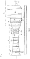
- FIG. 2A is a schematic side view of high pressure turbine section 12D used in gas generator 12 of industrial gas turbine engine 10 of FIG. 1 showing first stage turbine blade 24, second stage turbine blade 32, third stage turbine blade 34, first stage vane 22, second stage vane 26 and third stage vane 36. Vanes 22, 26 and 36 are suspended from engine case 28, while blades 24, 32 and 34 extend from rotor wheels 30, 38 and 40, respectively. High energy gas produced by combustor section 12C flows along gas path G in an axial direction, which extends sequentially past vanes 22, 26 and 36 and blades 24, 32 and 34.
- Gas turbine engine 10 may include additional stages of blades (also known as buckets) and vanes (also known as nozzles), such as in low pressure turbine section 12E, that can incorporate the features of the present disclosure, but are not described for brevity. While an embodiment of the engine has been described having low and high pressure turbine sections with connection to a generator via a power turbine, it will be appreciated that the scope of the disclosure is not so limited, and may apply to other arrangements, such as to have a single turbine section, and connection to a generator, via the compressor shaft, for example.
- Blades 24, 32 and 34 rotate at high speed on wheels 30, 38 and 40 and are therefore subject to radial loading. Additionally, blades 24, 32 and 34 are subject to axial loading from the high energy gases flowing through engine 10. It is desirable to maintain blades 24, 32 and 34 secured to wheels 30, 38 and 40 in order to, among other things, prevent damage to surrounding components, such as vanes 22, 26 and 36. Radial retention of blades can be provided by a blade root and wheel slot interface, while axial retention of blades can be provided by a lockwire.
- first stage blade 24 includes a shank 41, from which airfoil 44 extends.
- FIG. 2B is a rear perspective view of an exemplary first stage of turbine section 12D of FIG. 2A .
- a blade root 42 is attached to the shank 41 and is axially inserted into slot or groove 46 of wheel 30.
- Conventional fir tree or dovetail engagements can be used to prevent radial displacement of root 42 from groove 46.
- Blade root 42 and groove 46 may include features that, together with a lockwire, form retention mechanism 48 for axially restraining blade 24 within wheel 30.
- blade root 42 includes hook 74, which forms a circumferential slot into which the lockwire can be disposed.
- Hook 74 is shown extending from an aft surface of blade root 42.
- lockwires and locking keys of the present disclosure can also be used on forward areas of blades and wheels, (as shown in FIG. 2A ) for the third stage blade 34.
- the lockwires and locking keys of the present disclosure are discussed with reference to a turbine section, they may also be used in compressor sections of gas turbine engines.
- FIG. 3 is a close-up view of first stage turbine blade 24 of turbine section 12D of FIG. 2A disposed behind post 58, in groove 46 of rotor wheel 30 with locking key 52 disposed to retain lockwire 54 and retention pin 56 disposed to retain locking key 52.
- Blade root 42 includes inner surface 62 disposed between forward surface 60, and aft surface 64, which are shown behind forward surface 66, groove 46 and aft surface 68 of post 58.
- Blade 24 is connected to rotor wheel 30 such that inner surface 62 of root 42 contacts or interfaces with groove 46.
- hook 74 extends axially rearward from aft surface 64 and radially inward to form circumferential slot 72.
- circumferential slot 72 of the blade 24 aligns with circumferential slots 70 in the post 58.
- Turbine blade root 42 is connected to and retained within one of a plurality grooves 46 within rotor wheel 30 via lockwire 54.
- Counter-weight key 73 can also be attached to rotor wheel 30 to provide rotational balance.
- Blade root 42 includes hook 74, which extends axially rearward and inward from aft surface 64 to form circumferential slot 72.
- Hook 50 extends axially rearward from aft surface 68 and radially inward to form circumferential slot 70.
- Circumferential slot 72 of blade root 42 aligns with circumferential slots 70 of posts 58.
- lockwire 54 can be threaded through slots 70 and 72 to substantially surround or circumscribe rotor wheel 30 near an outer circumference or perimeter of rotor wheel 30.
- Lockwire 54 is, however, located within the outer periphery of rotor wheel 30 so as to extend across grooves 46 to restrain blade roots 42.
- Locking key 52 can be positioned within one of slots 70 between ends of lockwire 54. Locking key 52 can be retained by pin 56 inserted into bore 75 to prevent displacement of the key 52, and therefore lockwire 54.
- other fasteners than a pin can be used to link locking key 52 to rotor wheel 30, such as screws, bolts and the like.
- Counter-weight key 73 can be disposed in engine 10 opposite locking key 52 on rotor wheel 30 to offset any rotational imbalance produced by locking key 52.
- Counter-weight key 73 can be attached using a pin in a substantially similar manner as locking key 52.
- locking key 52 has a weight that is small enough to not affect the rotation of rotor wheel 30 such that counter-weight key 73 can be omitted.
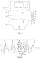
- FIG. 4A is a rear end view of the first stage turbine of FIG. 2B showing locking key 52 disposed between blade roots 42 and ends 78A and 78B of lockwire 54.
- FIG. 4B is a bottom perspective view of the first stage turbine of FIG. 2B showing locking key 52 disposed between blade roots 42 and ends 78A and 78B of lockwire 54.
- Blade root 42 may also include slot 76, which extends upward into the inward-most surface of hook 74 across where lockwire 54 is disposed. Slot 76 allows a tool, such as a pick, to be inserted into slot 72 to interface with lockwire 54. For example, the tool can be inserted into slot 72 to bend an end of lockwire 54 inward so as to be accessible outside of slots 70 and 72. Opposing ends 78A, 78B of lockwire 54 are disposed between adjacent blade roots 42.
- Locking key 52 includes central portion 80 and arms 82A and 82B.
- Central portion 80 includes cut-out 84 into which pin 56 can be disposed to retain locking key 52 against post 58 within circumferential slot 70 ( FIG. 2B ).
- Central portion 80 extends far enough radially outwardly to be at least partially positioned between ends 78A and 78B of lockwire 54. As such, lockwire 54 is prevented from circumferentially rotating beyond a limited amount allowed by the difference of the gap between ends 78A and 78B and the width of central portion 80.
- Central portion 80 includes arms 82A and 82B that extend circumferentially from central portion 80 and are positioned underneath ends 78A and 78B, respectively, to prevent radially inward displacement of ends 78A and 78B. The length of each of arms 82A and 82B is greater than the aforementioned limited amount to ensure that ends 78A and 78B cannot slip off of arms 82A and 82B.
- locking key 52 is almost the same size as the width of slots 70 and 72. Locking key 52 is, however, slightly narrower in order to fit with appropriate clearance within hooks 50 and 74, adjacent aft surfaces 64, 68. Locking key 52 is sized so as to freely slide between the aforementioned surfaces under influence from a technician or other service personnel, but is not so loose so as to unduly vibrate
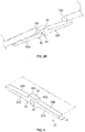
- FIG. 5A is a perspective view of a first embodiment of locking key 52 of FIGS. 3 - 4B showing lockwire 54 in a cold position.
- FIG. 5B is a perspective view of the first embodiment of locking key 52 of FIG. 5A showing lockwire 54 in a hot position.
- ends 78A and 78B are positioned on either side of central portion 80 such as the distances therebetween are random. In one embodiment, ends 78A and 78B abut central portion 80 such that very little or no space is provided between ends 78A and 78B and central portion 80.
- lockwire 54 is installed so that ends 78A and 78B are equally spaced from central portion 80.
- central portion 80 need not be centered and lockwire 52 can be installed with any amount of gap between central portion 80 and either of ends 78A and 78B.
- the spaces between upper surfaces of arms 82A and 82B and the underside of hooks 50 and 74 is approximately equal to the diameter of lockwire 54 (as can be seen in FIG. 7 ) such that lockwire 54 can only be installed with ends 78A and 78B opposite central portion 80.
- lockwire 54 In a hot state, such as when gas turbine engine 10 comes up to operating temperatures, lockwire 54 is subject to a combination of various stresses and strains, such as from thermal growth and centrifugal force. As such, lockwire 54 can expand such that the overall hoop diameter of lockwire 54 increases. In such a condition, the gap distance between ends 78A and 78B can grow to be greater than in the cold state. As such, arms 82A and 82B need to be long enough to accommodate and continue to radially restrain ends 78A and 78B retreating from central portion 80.
- lockwire 54 can be pushed or urged toward one side of central portion 80.
- end 78A of lockwire 54 can be urged toward central portion 80 so as to abut central portion 80, thereby pushing end 78B away from central portion 80.
- arms 82A and 82B are each long enough to accommodate having the entirety of the gap length between ends 78A and 78B on one side of central portion 80.
- locking key 52 can include only one of arms 82A and 82B to support one of ends 78A and 78B.
- arm 82A can be omitted from locking key 52.
- the opposite side of central portion 80 facing end 78A can be coated with a friction increasing feature, such as diamond grit.
- FIG. 6 is a perspective view of locking key 52 of FIGS. 5A and 5B showing arms 82A and 82B extending laterally from central portion 80.
- Central portion 80 includes cut-out 84 and tab 86, which has sidewalls 88A and 88B.
- Arms 82A and 82B extend laterally from central portion 80 at sidewalls 88A and 88B, respectively.
- Arms 82A and 82B include outer surfaces 90A and 90B, respectively.
- Central portion 80 comprises a generally rectilinear body having a lower portion disposed between arms 82A and 82B, and an upper portion defined by tab 86.
- cut-out 84 extends upward into an inner surface of central portion 80 towards tab 86.
- locking key 52 has the same thickness T throughout its length L.
- FIG. 7 is a front view of locking key 52 of FIGS. 5A and 5B showing circumferential curvature of arms 82A and 82B.
- locking key 52 is shown schematically in front of aft surfaces 64 of turbine blades 24 and aft surface 68 of rotor wheel 30, and below cut-away portions of hooks 74 of turbine blades 24 and hook 50 or rotor wheel 30 (See FIG. 2B ).
- Tab 86 is disposed between ends 78A and 78B of lockwire 54, thereby serving as a circumferential stop for lockwire 54 that inhibits and, ultimately, prevents circumferential rotation of lockwire 54.
- Arms 82A and 82B extend generally laterally from central portion 80.
- outer surfaces 90A and 90B can be provided with a slight circumferential curvature to match the curvature of lockwire 54.
- outer surfaces 90A and 90B can be flat and angled slightly inward from tab 86 at angle A.
- FIG. 8A is a front view of locking key 100 of the present disclosure showing an aperture 102, such as a through hole, for engaging retention pin 56 and aerodynamic wings 104A and 104B for supporting lockwire 54.
- FIG. 8B is a side view of locking key 100 of FIG. 8A showing a saddle 108.
- FIG. 8C is a perspective view of locking key 100 of FIGS. 8A and 8B disposed between ends 78A and 78B of lockwire 54.
- Locking key 100 also includes central portion 110 including tab 112, and supports 114A and 114B.
- Wings 104A and 104B include outer surfaces 116A and 116B, respectively, for supporting ends of lockwire 54.
- Tab 112 is sized to fit between the ends of lockwire 54.
- Tab 112 and wings 104A and 104B have the same thickness, as can be seen in FIG. 8B , which is approximately equal to the diameter of lockwire 54.
- supports 114A and 114B are not as thick as wings 104A and 104B, which allows for the formation of cut-back 106 that permits grinding away of retention pin 56.
- cut-back 106 provides a space between supports 114A and 114B and the aft-most portions of hook 50 ( FIG. 2B ) to permit a grinding tool to clearly access pin 56.
- Wings 104A and 104B include saddles 108 for engaging lockwire 54.
- Saddles 108 provide a curved surface, or cup, for receiving ends 78A and 78B of lockwire 54 that can help guide ends 78A and 78B along wings 104A and 104B during the movements of lockwire 54 described with reference to FIGS. 5A and 5B .
- Supports 114A and 114B each also have a V-shape that provides an aerodynamic shape to locking key 100 in both possible directions of rotation of rotor wheel 30.
- supports 114A and 114B are small near their lateral tips, e.g. in the leading edge direction of rotation and grow in size or height near central portion 80 to push air out around locking key 100 during rotation.
- FIG. 8C also illustrates an embodiment where ends 78A and 78B of lockwire 54 contact or are in close proximity to tab 112.
- FIG. 9 is a front view of locking key 100B of the present disclosure showing a slot, or cut-out, 118 for engaging retention pin 56.
- Locking key 100B of FIG. 9 is substantially the same as locking key 100 of FIG. 8A , except that slot 118 replaces through-hole 106.
- Slot 118 provides similar linking of locking key 100B to rotor wheel 30 as locking key 100, but provides less radial restraint to locking key 100B to facilitate easier alignment with bore 75 and pin 56 to ease installation.
- Locking key 52 can be installed using the following method. First, one of ends 78A and 78B of lockwire 54 can be inserted into slot 70 of hook 50 adjacent to bore 75 for pin 56. Lockwire 54 can then be pushed into slots 70 and 72 of blades 24 and posts 58, respectively, around the circumference of rotor wheel 30. Where ends 78A and 78B of lockwire 54 meet again on the opposite side of bore 75, lockwire 54 can be measured and marked so that there will be a gap between ends 78A and 78B equal to the width of tab 86. One of ends 78A and 78B can be partially removed and ground so that the gap between ends 78A and 78B matches, or is slightly larger than, the width of tab 86.
- Ends 78A and 78B can be reinserted into slots 70 and 72 to verify the gap length directly where pin 56 will be before inserting locking key 52 into the gap between ends 78A and 78B. Ends 78A and 78B will rest on arms 82A and 82B. Pin 56 can be inserted into bore 75 and cut-out 84 or another slot or through-bore. Locking keys 100 and 100B can be installed in a similar fashion.
- pin 56 is ground from the underside of hooks 50 and 74 within slots 70 and 72 ( FIG. 2B ). Grinding can be concentrated in the area of cut-out 84 in order to minimize the amount of material that is ground away (e.g., by minimizing grinding of portions of locking key 52). The remaining portion of pin 56 can be pushed or pulled out of bore 75 in any conventional manner, such as by pushing it through bore 75 with a punch tool. As mentioned, the thickness T of locking key 52 is such that locking key 52 can be loose enough to fall out of slots 70 and 72. Subsequently, lockwire 54 can be pulled out using wire removal slot 76 in blade 24. Lockwire 54 can be pulled out over the span of slots 70 and 72. Locking keys 100 and 100b can be removed in a similar fashion.
- the locking keys of the present disclosure prevent circumferential rotation of the lockwire and additionally provide radial inner support to ends of the lockwire to prevent lockwire disengagement.
- the through-hole or slot in the locking key captures the pin used to restrain the lockwire to hold the locking key in place.
- the locking key can also include a tab extending from the outer diameter of the locking key to prevent the lockwire from rotating. Arms or wings of the locking key cradle the lockwire and extend long enough to account for changes in the geometry of the lockwire that can cause the gap between ends of the lockwire to grow.
- the locking key can have only one wing or arm.
- the central tab provides a reference width for grinding the gap length between ends of the lockwire to ensure a snug installation fit.
- the locking key can include a cut-back portion to allow for grinding away of the retention pin and removal of the locking key.
- the locking key can be a one-time use part that that can be inexpensively replaced and installed without requiring modifications of the engine or lockwire.
- the locking key can be used with a counter-weight key on an opposite side of the rotor wheel to assist in balanced operation of the gas turbine engine.
- Locking keys 52 and 100 of the present disclosure and the associated concepts described herein provide advantages to the operation of gas turbine engine 10.
- the concepts solve all understood rotation and wire retention issues.
- By capturing the retention pin movement of the locking key is prevented during operation of the engine.
- the tab on the locking key prevents the lockwire from moving circumferentially.
- Support from circumferential or lateral extension of the arms or wings of the locking key secure ends of the lockwire in an outboard position, while simultaneously allowing for growth in the gap between ends of the lockwire.
- the locking keys described herein are inexpensive to manufacture and can be easily replaced, thereby reducing or eliminating modifications.
- the locking keys are easy to install and remove, such as without modification of the engine or locking key.
Landscapes
- Engineering & Computer Science (AREA)
- Mechanical Engineering (AREA)
- General Engineering & Computer Science (AREA)
- Turbine Rotor Nozzle Sealing (AREA)
Description
- The present application pertains generally, but not by way of limitation, to gas turbine engines. More particularly, the present application is directed to devices and systems for axially retaining blades in slots of rotor disks or wheels.
- Gas turbine engines operate by passing a volume of gases through a series of compressors and turbines in order to produce rotational shaft power. High energy gases rotate a high pressure turbine to generate the shaft power. The shaft power drives a high pressure compressor to provide compressed air to a combustion process that generates the high energy gases for turning the high pressure turbine. The high energy gases can also be used to rotate another turbine for additional purposes. In an aircraft engine, a low pressure turbine can be used to generate propulsion, such as directly via thrust, or indirectly via a shaft and fan or propeller. In an industrial gas turbine, a power turbine can be used to drive a shaft for powering a generator that produces electricity.
- Each compressor and turbine comprises a plurality of stages of vanes and blades, each vane and blade including an airfoil. In general, stators redirect the trajectory of the air coming off the blades for flow into the next stage. In the compressor, stators convert kinetic energy of moving air into pressure, while, in the turbine, stators accelerate pressurized air to extract kinetic energy. In the compressor, the rotating blades push air past the stationary vanes. In the turbine, the rotating blades extract rotational power from the flowing air.
- Typically, blades used in turbines and compressors are removable from the rotor wheel in order to perform maintenance or replace the blades. Thus, various solutions have been implemented to prevent displacement of the blades within the rotor wheel. In one system, a lockwire is disposed near the outer circumference of the rotor wheel to block axial movement of roots of the blades. These designs, however, can experience issues related to circumferential motion of the lockwire. This can, in some instances, compromise retention of the lockwire, potentially allowing axial liberation of the blades. For example, one or more ends of the lockwire can become radially displaced as the lockwire circumferentially rotates, thereby causing ends of the lockwire to be pushed radially inward of the blade roots. Thus, the blades can become unrestrained in the axial direction and can become displaced.
- Several attempts have been made to address circumferential displacement of lockwires.
U.S. Pat. No. 8,905,717 (EP 2439378 A2) to Roman-Morales et al. proposes to solve this problem via attachment of tabs onto the lockwire that will restrict lockwire circumferential motion via interference with radial retention features, such as pins, connected to the rotor wheel. With continued operation, and/or potential weld issues, these tabs may break free and represent a potential risk of domestic object damage to the turbine.U.S. Pub. No. 2014/0112793 (EP 2722484 A2) to Latimer et al. introduces circumferential stops between ends of the lockwire to prevent circumferential motion the lockwire; however these stops do not provide any radial support, and therefore requires additional, separate components to provide radial retention.U.S. Pat. No. 8,485,784 to Eastman et al. discloses other approaches for restricting circumferential motion via attachment of pins to the lockwire. - The present inventors have recognized, among other things, potential shortcomings of previous attempted solutions to the problem of circumferential lockwire rotation. For example, the attachment of welded tabs or pins to the lockwire can add significant manufacturing complexity to the wire. Additionally, such features may become detached in operation, providing cause for potential foreign object damage in operation.
- The present inventors have also recognized that a problem to be solved with lockwires includes the tendency for lockwires to circumferentially rotate, which can then cause radial displacement of ends of the lockwire, even with some of the aforementioned attempted solutions. For example, providing stops that only limit circumferential motion of the lockwire fail to inhibit radial motion of the lockwire and are therefore potentially susceptible to the lockwire slipping under the circumferential stop.
- Furthermore, the present inventors have recognized that problems associated with circumferential and radial displacement of lockwires can become exacerbated by thermal or mechanical growth of the lockwire, which can cause free ends of the lockwire to grow apart and increase their chances of slipping under a circumferential stop or retention pins within the engine.
- The subject matter of the present disclosure can help provide solutions to these and other problems, such as by providing a locking key that radially supports ends of the lockwire over a range of distances between ends of the lockwire caused by temperature and mechanical variations within the engine during operation, in addition to providing a circumferential rotational stop.
- The present invention provides a retention system for turbine blades in a gas turbine engine as defined in
claim 1. - The present invention further provides a gas turbine engine system as defined in claim 3.
- In one example, a gas turbine engine system comprises a rotor wheel, a plurality of blades, a lockwire and a locking key. The rotor wheel comprises a plurality of axial grooves extending through a periphery of the rotor wheel, and a plurality of posts formed between adjacent slots, each post having a circumferential slot. The plurality of blades are mounted in the plurality of axial grooves of the rotor wheel, and each blade has a circumferential slot circumferentially aligned with the circumferential slots of the plurality of posts. The lockwire extends across the plurality of axial grooves of the rotor wheel within each of the circumferential slots of the posts and blades from a first end to a second end to inhibit axial displacement of the plurality of blades within the plurality of grooves. The locking key is disposed between the first and second ends of the lockwire to provide support to at least one of the ends of the lockwire and prevent at least one end from being displaced radially inward.
- The locking key can be comprised of a central portion positioned between the ends of the lockwire. The central portion links the locking key to the rotor wheel, with first and second arms extending laterally outward from the central portion to restrict radial inward displacement of the first and second ends of the lockwire.
- This overview is intended to provide an overview of subject matter of the present patent application. It is not intended to provide an exclusive or exhaustive explanation of the invention. The detailed description is included to provide further information about the present patent application.
-
-
FIG. 1 is a partially broken away side view of an industrial gas turbine engine showing a portion of a turbine section of a gas generator disposed between a combustor section and a power generator. -
FIG. 2A is a schematic side view of the turbine section used in the gas generator of the industrial gas turbine engine ofFIG. 1 showing a plurality of stages of turbine blades and vanes. -
FIG. 2B is a rear perspective view of the first stage of the turbine section ofFIG. 2A showing a locking key exploded from a rotor wheel having a plurality of slots and a turbine blade root connected to one of the slots with a lockwire disposed to retain the blade root within the slot. -
FIG. 3 is a close-up view of a first stage turbine blade of the turbine section ofFIG. 2A disposed in a slot of a rotor wheel with a locking key disposed to retain the lockwire and a retention pin disposed to retain the locking key. -
FIG. 4A is a rear end view of the first stage turbine ofFIG. 2B showing the locking key disposed between blade roots and ends of the lockwire. -
FIG. 4B is a bottom perspective view of the first stage turbine ofFIG. 2B showing the locking key disposed between blade roots and ends of the lockwire. -
FIG. 5A is a perspective view of a first embodiment of the locking key ofFIGS. 3 - 4B showing the lockwire in a cold position. -
FIG. 5B is a perspective view of the first embodiment of the locking key ofFIG. 5A showing the lockwire in a hot position. -
FIG. 6 is a perspective view of the locking key ofFIGS. 5A and5B showing arms extending laterally from a central portion. -
FIG. 7 is a front view of the locking key ofFIGS. 5A and5B showing circumferential curvature of the arms. -
FIG. 8A is a front view of a second embodiment of the locking key of the present disclosure showing a through-hole for engaging a retention pin and aerodynamic wings for supporting the lockwire. -
FIG. 8B is a side view of the locking key ofFIG. 8A showing a cut-back to allow for grinding away of the retention pin and a saddle for engaging the lockwire. -
FIG. 8C is a perspective view of the locking key ofFIGS. 8A and 8B disposed between ends of a lockwire. -
FIG. 9 is a front view of a third embodiment of the locking key of the present disclosure showing a slot for engaging a retention pin and aerodynamic wings for supporting the lockwire. - In the drawings, which are not necessarily drawn to scale, like numerals may describe similar components in different views. Like numerals having different letter suffixes may represent different instances of similar components. The drawings illustrate generally, by way of example, but not by way of limitation, various embodiments discussed in the present document.
-
FIG. 1 is a partially broken away side view ofgas turbine engine 10 showinggas generator 12 connected topower generator 13 via power turbine inlet (PTI) 16. In the illustrated embodiment,gas turbine engine 10 is an industrial gas turbine engine circumferentially disposed about a central, longitudinal axis or axial engine centerline CL.Gas generator 12 includes, in series order from front to rear, lowpressure compressor section 12A, highpressure compressor section 12B,combustor section 12C, highpressure turbine section 12D, and low pressure turbine section12E. Power generator 13 comprisesPTI 16,power turbine 14, which is disposed aft of lowpressure turbine section 12E,output shaft 18 and exhaust duct 20. Rotation ofpower turbine 14 drivesoutput shaft 18, which may be coupled to an electrical generator (not shown) that is also part ofpower generator 13. Gas generated bygas generator 12 passes throughpower turbine 14 and leavesengine 10 at exhaust duct 20. - As is known in the art of gas turbine engines, incoming ambient air becomes pressurized within low and high
pressure compressors sections combustor section 12C, where it is burned. Once burned, combustion gases expand through high and lowpressure turbine sections PTI 16. FromPTI 16, the combustion gases flow intopower turbine 14. High and lowpressure turbine sections engine 10 that rotate in response to the flow of the combustion gases thereby rotating the attached high and lowpressure compressor sections FIG. 1 is described with reference to high and low pressure spools, the present disclosure may be used with single spool engines having only a single compressor stage and a single turbine stage. -
Power turbine 14 may, for example, drive an electrical generator, pump, or gearbox (not shown). It is understood thatFIG. 1 provides a basic understanding and overview of the various sections and the basic operation of an industrial gas turbine engine. It will become apparent to those skilled in the art that the present application is applicable to all types of gas turbine engines, including those with aerospace or aircraft applications. Similarly, although the present disclosure is described with reference to turbine blades, the present invention is applicable to other components of gas turbine engines, such as compressor blades, fan blades and the like. - High
pressure turbine section 12D comprises first stage vane 22, firststage turbine blade 24 andsecond stage vane 26. First stage vane 22 andsecond stage vane 26 are joined toengine case 28 at their radially outer ends. Firststage turbine blade 24 is connected to firststage rotor wheel 30 at its radially inner end. The present disclosure is directed towards features for retainingturbine blade 24 within its attachment torotor wheel 30. -
FIG. 2A is a schematic side view of highpressure turbine section 12D used ingas generator 12 of industrialgas turbine engine 10 ofFIG. 1 showing firststage turbine blade 24, secondstage turbine blade 32, thirdstage turbine blade 34, first stage vane 22,second stage vane 26 andthird stage vane 36.Vanes engine case 28, whileblades rotor wheels combustor section 12C flows along gas path G in an axial direction, which extends sequentiallypast vanes blades Gas turbine engine 10 may include additional stages of blades (also known as buckets) and vanes (also known as nozzles), such as in lowpressure turbine section 12E, that can incorporate the features of the present disclosure, but are not described for brevity. While an embodiment of the engine has been described having low and high pressure turbine sections with connection to a generator via a power turbine, it will be appreciated that the scope of the disclosure is not so limited, and may apply to other arrangements, such as to have a single turbine section, and connection to a generator, via the compressor shaft, for example. -
Blades wheels blades engine 10. It is desirable to maintainblades wheels vanes first stage blade 24 includes ashank 41, from whichairfoil 44 extends. -
FIG. 2B is a rear perspective view of an exemplary first stage ofturbine section 12D ofFIG. 2A . With reference toFIGS. 2A and2B , ablade root 42 is attached to theshank 41 and is axially inserted into slot or groove 46 ofwheel 30. Conventional fir tree or dovetail engagements can be used to prevent radial displacement ofroot 42 fromgroove 46.Blade root 42 andgroove 46 may include features that, together with a lockwire,form retention mechanism 48 for axially restrainingblade 24 withinwheel 30. In particular,blade root 42 includeshook 74, which forms a circumferential slot into which the lockwire can be disposed. -
Hook 74 is shown extending from an aft surface ofblade root 42. However, lockwires and locking keys of the present disclosure can also be used on forward areas of blades and wheels, (as shown inFIG. 2A ) for thethird stage blade 34. Likewise, although the lockwires and locking keys of the present disclosure are discussed with reference to a turbine section, they may also be used in compressor sections of gas turbine engines. -
FIG. 3 is a close-up view of firststage turbine blade 24 ofturbine section 12D ofFIG. 2A disposed behindpost 58, ingroove 46 ofrotor wheel 30 with locking key 52 disposed to retainlockwire 54 andretention pin 56 disposed to retain lockingkey 52.Blade root 42 includesinner surface 62 disposed betweenforward surface 60, andaft surface 64, which are shown behindforward surface 66,groove 46 and aft surface 68 ofpost 58. -
Blade 24 is connected torotor wheel 30 such thatinner surface 62 ofroot 42 contacts or interfaces withgroove 46. On an exemplary firststage turbine blade 24,hook 74 extends axially rearward fromaft surface 64 and radially inward to formcircumferential slot 72. As can be seen inFIG. 2B ,circumferential slot 72 of theblade 24 aligns withcircumferential slots 70 in thepost 58. - As shown in
FIG. 2B , lockingkey 52 is exploded fromrotor wheel 30.Turbine blade root 42 is connected to and retained within one of aplurality grooves 46 withinrotor wheel 30 vialockwire 54. Counter-weight key 73 can also be attached torotor wheel 30 to provide rotational balance.Blade root 42 includeshook 74, which extends axially rearward and inward fromaft surface 64 to formcircumferential slot 72.Hook 50 extends axially rearward fromaft surface 68 and radially inward to formcircumferential slot 70. -
Circumferential slot 72 ofblade root 42 aligns withcircumferential slots 70 ofposts 58. As such, lockwire 54 can be threaded throughslots rotor wheel 30 near an outer circumference or perimeter ofrotor wheel 30.Lockwire 54 is, however, located within the outer periphery ofrotor wheel 30 so as to extend acrossgrooves 46 to restrainblade roots 42. Locking key 52 can be positioned within one ofslots 70 between ends oflockwire 54. Locking key 52 can be retained bypin 56 inserted intobore 75 to prevent displacement of the key 52, and therefore lockwire 54. In other embodiments, other fasteners than a pin can be used to link locking key 52 torotor wheel 30, such as screws, bolts and the like. Counter-weight key 73 can be disposed inengine 10 opposite lockingkey 52 onrotor wheel 30 to offset any rotational imbalance produced by lockingkey 52. Counter-weight key 73 can be attached using a pin in a substantially similar manner as lockingkey 52. However, in various embodiments, lockingkey 52 has a weight that is small enough to not affect the rotation ofrotor wheel 30 such that counter-weight key 73 can be omitted. -
FIG. 4A is a rear end view of the first stage turbine ofFIG. 2B showing locking key 52 disposed betweenblade roots 42 and ends 78A and 78B oflockwire 54.FIG. 4B is a bottom perspective view of the first stage turbine ofFIG. 2B showing locking key 52 disposed betweenblade roots 42 and ends 78A and 78B oflockwire 54. -
Blade root 42 may also includeslot 76, which extends upward into the inward-most surface ofhook 74 across wherelockwire 54 is disposed.Slot 76 allows a tool, such as a pick, to be inserted intoslot 72 to interface withlockwire 54. For example, the tool can be inserted intoslot 72 to bend an end oflockwire 54 inward so as to be accessible outside ofslots lockwire 54 are disposed betweenadjacent blade roots 42. - Locking
key 52 includescentral portion 80 andarms Central portion 80 includes cut-out 84 into whichpin 56 can be disposed to retain locking key 52 againstpost 58 within circumferential slot 70 (FIG. 2B ).Central portion 80 extends far enough radially outwardly to be at least partially positioned between ends 78A and 78B oflockwire 54. As such, lockwire 54 is prevented from circumferentially rotating beyond a limited amount allowed by the difference of the gap between ends 78A and 78B and the width ofcentral portion 80.Central portion 80 includesarms central portion 80 and are positioned underneath ends 78A and 78B, respectively, to prevent radially inward displacement ofends arms arms - As can be seen in
FIG. 4B , the thickness of lockingkey 52 is almost the same size as the width ofslots key 52 is, however, slightly narrower in order to fit with appropriate clearance withinhooks key 52 is sized so as to freely slide between the aforementioned surfaces under influence from a technician or other service personnel, but is not so loose so as to unduly vibrate -
FIG. 5A is a perspective view of a first embodiment of lockingkey 52 ofFIGS. 3 - 4B showing lockwire 54 in a cold position.FIG. 5B is a perspective view of the first embodiment of lockingkey 52 ofFIG. 5A showing lockwire 54 in a hot position. - In a cold state, such as when lockwire 54 and locking
key 52 are installed intogas turbine engine 10, ends 78A and 78B are positioned on either side ofcentral portion 80 such as the distances therebetween are random. In one embodiment, ends 78A and 78B abutcentral portion 80 such that very little or no space is provided betweenends central portion 80. Generally, lockwire 54 is installed so that ends 78A and 78B are equally spaced fromcentral portion 80. However,central portion 80 need not be centered and lockwire 52 can be installed with any amount of gap betweencentral portion 80 and either ofends - In one embodiment, the spaces between upper surfaces of
arms hooks FIG. 7 ) such that lockwire 54 can only be installed withends central portion 80. - In a hot state, such as when
gas turbine engine 10 comes up to operating temperatures, lockwire 54 is subject to a combination of various stresses and strains, such as from thermal growth and centrifugal force. As such, lockwire 54 can expand such that the overall hoop diameter oflockwire 54 increases. In such a condition, the gap distance between ends 78A and 78B can grow to be greater than in the cold state. As such,arms central portion 80. - Furthermore, due to centripetal forces from rotation of
rotor wheel 30, lockwire 54 can be pushed or urged toward one side ofcentral portion 80. Depending on the rotational direction ofturbine section 12D,end 78A oflockwire 54 can be urged towardcentral portion 80 so as to abutcentral portion 80, thereby pushingend 78B away fromcentral portion 80. As such,arms central portion 80. In one embodiment, lockingkey 52 can include only one ofarms ends end 78B will slide away fromcentral portion 80, whileend 78A remains engaged withcentral portion 80,arm 82A can be omitted from lockingkey 52. In such an embodiment, the opposite side ofcentral portion 80 facingend 78A can be coated with a friction increasing feature, such as diamond grit. -
FIG. 6 is a perspective view of lockingkey 52 ofFIGS. 5A and5B showing arms central portion 80.Central portion 80 includes cut-out 84 andtab 86, which has sidewalls 88A and 88B.Arms central portion 80 atsidewalls Arms outer surfaces -
Central portion 80 comprises a generally rectilinear body having a lower portion disposed betweenarms tab 86. In the embodiment ofFIG. 6 , cut-out 84 extends upward into an inner surface ofcentral portion 80 towardstab 86. In one embodiment, lockingkey 52 has the same thickness T throughout its length L. -
FIG. 7 is a front view of lockingkey 52 ofFIGS. 5A and5B showing circumferential curvature ofarms FIG. 7 , lockingkey 52 is shown schematically in front ofaft surfaces 64 ofturbine blades 24 and aft surface 68 ofrotor wheel 30, and below cut-away portions ofhooks 74 ofturbine blades 24 andhook 50 or rotor wheel 30 (SeeFIG. 2B ).Tab 86 is disposed betweenends lockwire 54, thereby serving as a circumferential stop forlockwire 54 that inhibits and, ultimately, prevents circumferential rotation oflockwire 54.Arms central portion 80. However,outer surfaces lockwire 54. Alternatively,outer surfaces tab 86 at angle A. -
FIG. 8A is a front view of lockingkey 100 of the present disclosure showing anaperture 102, such as a through hole, for engagingretention pin 56 andaerodynamic wings lockwire 54.FIG. 8B is a side view of lockingkey 100 ofFIG. 8A showing asaddle 108.FIG. 8C is a perspective view of lockingkey 100 ofFIGS. 8A and 8B disposed betweenends lockwire 54. - Locking key 100 also includes
central portion 110 includingtab 112, and supports 114A and 114B.Wings outer surfaces lockwire 54.Tab 112 is sized to fit between the ends oflockwire 54.Tab 112 andwings FIG. 8B , which is approximately equal to the diameter oflockwire 54. - As can also be seen in
FIG. 8B , supports 114A and 114B are not as thick aswings back 106 that permits grinding away ofretention pin 56. In particular, cut-back 106 provides a space betweensupports FIG. 2B ) to permit a grinding tool to clearly accesspin 56. -
Wings saddles 108 for engaginglockwire 54.Saddles 108 provide a curved surface, or cup, for receiving ends 78A and 78B oflockwire 54 that can help guideends wings lockwire 54 described with reference toFIGS. 5A and5B . -
Supports rotor wheel 30. For example, supports 114A and 114B are small near their lateral tips, e.g. in the leading edge direction of rotation and grow in size or height nearcentral portion 80 to push air out around locking key 100 during rotation.FIG. 8C also illustrates an embodiment where ends 78A and 78B oflockwire 54 contact or are in close proximity totab 112. -
FIG. 9 is a front view of locking key 100B of the present disclosure showing a slot, or cut-out, 118 for engagingretention pin 56. Locking key 100B ofFIG. 9 is substantially the same as lockingkey 100 ofFIG. 8A , except thatslot 118 replaces through-hole 106.Slot 118 provides similar linking of locking key 100B torotor wheel 30 as lockingkey 100, but provides less radial restraint to locking key 100B to facilitate easier alignment withbore 75 andpin 56 to ease installation. - Locking key 52 can be installed using the following method. First, one of
ends lockwire 54 can be inserted intoslot 70 ofhook 50 adjacent to bore 75 forpin 56.Lockwire 54 can then be pushed intoslots blades 24 andposts 58, respectively, around the circumference ofrotor wheel 30. Where ends 78A and 78B oflockwire 54 meet again on the opposite side ofbore 75, lockwire 54 can be measured and marked so that there will be a gap between ends 78A and 78B equal to the width oftab 86. One of ends 78A and 78B can be partially removed and ground so that the gap between ends 78A and 78B matches, or is slightly larger than, the width oftab 86.Ends slots pin 56 will be before inserting locking key 52 into the gap between ends 78A and 78B.Ends arms Pin 56 can be inserted intobore 75 and cut-out 84 or another slot or through-bore. Lockingkeys - In order to remove locking
key 52,pin 56 is ground from the underside ofhooks slots 70 and 72 (FIG. 2B ). Grinding can be concentrated in the area of cut-out 84 in order to minimize the amount of material that is ground away (e.g., by minimizing grinding of portions of locking key 52). The remaining portion ofpin 56 can be pushed or pulled out ofbore 75 in any conventional manner, such as by pushing it through bore 75 with a punch tool. As mentioned, the thickness T of lockingkey 52 is such that locking key 52 can be loose enough to fall out ofslots wire removal slot 76 inblade 24.Lockwire 54 can be pulled out over the span ofslots keys 100 and 100b can be removed in a similar fashion. - The locking keys of the present disclosure prevent circumferential rotation of the lockwire and additionally provide radial inner support to ends of the lockwire to prevent lockwire disengagement. The through-hole or slot in the locking key captures the pin used to restrain the lockwire to hold the locking key in place. The locking key can also include a tab extending from the outer diameter of the locking key to prevent the lockwire from rotating. Arms or wings of the locking key cradle the lockwire and extend long enough to account for changes in the geometry of the lockwire that can cause the gap between ends of the lockwire to grow. In various embodiments, the locking key can have only one wing or arm. The central tab provides a reference width for grinding the gap length between ends of the lockwire to ensure a snug installation fit. The locking key can include a cut-back portion to allow for grinding away of the retention pin and removal of the locking key. The locking key can be a one-time use part that that can be inexpensively replaced and installed without requiring modifications of the engine or lockwire. The locking key can be used with a counter-weight key on an opposite side of the rotor wheel to assist in balanced operation of the gas turbine engine.
- Locking
keys gas turbine engine 10. The concepts solve all understood rotation and wire retention issues. By capturing the retention pin, movement of the locking key is prevented during operation of the engine. The tab on the locking key prevents the lockwire from moving circumferentially. Support from circumferential or lateral extension of the arms or wings of the locking key secure ends of the lockwire in an outboard position, while simultaneously allowing for growth in the gap between ends of the lockwire. The locking keys described herein are inexpensive to manufacture and can be easily replaced, thereby reducing or eliminating modifications. The locking keys are easy to install and remove, such as without modification of the engine or locking key. - In this document, the terms "a" or "an" are used, as is common in patent documents, to include one or more than one, independent of any other instances or usages of "at least one" or "one or more." In this document, the term "or" is used to refer to a nonexclusive or, such that "A or B" includes "A but not B," "B but not A," and "A and B," unless otherwise indicated. In this document, the terms "including" and "in which" are used as the plain-English equivalents of the respective terms "comprising" and "wherein." Also, in the following claims, the terms "including" and "comprising" are open-ended, that is, a system, device, article, composition, formulation, or process that includes elements in addition to those listed after such a term in a claim are still deemed to fall within the scope of that claim. Moreover, in the following claims, the terms "first," "second," and "third," etc. are used merely as labels, and are not intended to impose numerical requirements on their objects.
- The above description is intended to be illustrative, and not restrictive. For example, the above-described examples (or one or more aspects thereof) may be used in combination with each other. Other embodiments can be used, such as by one of ordinary skill in the art upon reviewing the above description. The scope of the invention should be determined with reference to the appended claims.
Claims (15)
- A retention system for turbine blades (24) in a gas turbine engine having a lockwire (54) extending in a circular fashion from a first end (78A) to a second end (78B) such that a gap is present between the first and second ends (78A, 78B), the retention system comprising:a locking key (52; 100; 100B) comprising:
a central portion (80; 110) for placement between the first and second ends (78A, 78B) of the lockwire (54) to prevent circumferential rotation of the lockwire,characterized in that the locking key further comprises:
a pair of arms (82A, 82B; 104A, 104B) extending laterally from the central portion (80; 110) for providing radial support to the first and second ends (78A, 78B) of the lockwire (54). - The retention system of claim 1, wherein each arm (104A, 104B) has a saddle (108) for receiving an end (78A, 78B) of the lockwire (54); and/or
each arm (104A, 104B) has a height near the central portion that tapers toward a lateral end of each arm (104A, 104B); and/or
further comprising a pin (56) for extending through the central portion (80; 110) of the locking key (52; 100; 100B). - A gas turbine engine system comprising:the retention system of claim 1 or 2;a rotor wheel (30) comprising:a plurality of axial grooves (46) extending through a periphery of the rotor wheel (30); anda plurality of posts (58) formed between adjacent grooves (46), each post (58) having a circumferential slot (70);a plurality of blades (24) mounted in the plurality of axial grooves (46) of the rotor wheel (30), each blade (24) having a circumferential slot (72) circumferentially aligned with the circumferential slots (70) of the plurality of posts (58); andthe lockwire (54) extending across the plurality of axial grooves (46) of the rotor wheel (30) within each of the circumferential slots (72, 78) of the posts (58) and the blades (24) from the first end (78A) to the second end (78B) to inhibit axial displacement of the plurality of blades (24) within the plurality of axial grooves (46).
- The gas turbine engine system of claim 3, wherein the locking key (52; 100; 100B) comprises:a central portion (80; 110) positioned between the ends (78A, 78B) of the lockwire (54) and for linking the locking key to the rotor wheel; andat least one arm (82A, 82B; 104A, 104B) extending laterally from the central portion (80; 110) restricting radially inward displacement of at least one of the first and second ends (78A; 78B) of the lockwire (54).
- The gas turbine engine system of claim 4, wherein the locking key (52; 100; 100B) includes a pair of arms (82A, 82B; 104A, 104B) extending in opposite lateral directions from the central portion (80; 110) to support each of the first and second ends (78A, 78B) of the lockwire (54), respectively.
- The gas turbine engine system of claim 5, wherein each arm (104A, 104B) has a saddle (108) for receiving an end (78A; 78B) of the lockwire (54).
- The gas turbine engine system of claim 5 or 6, wherein each arm (104A, 104B) has a height near the central portion that tapers toward a lateral end of each arm.
- The gas turbine engine system of claim 5, 6 or 7, wherein the central portion (80; 110) comprises a tab (86; 112) located between the first and second ends (78A, 78B) of the lockwire (54), the tab (86; 112) projecting radially beyond outer surfaces of the pair of arms (82A, 82B; 104A, 104B) to provide a circumferential stop.
- The gas turbine engine system of claim 8, wherein the tab (86; 112) has a width approximately equal to a distance between the first and second ends (78A, 78B) of the lockwire (54), and/or wherein a distance between the first and second ends (78A, 78B) of the lockwire (54) grows from a first gap length to a second gap length during operation of the gas turbine engine system, and wherein each of the arms (82A, 82B' 104A, 104B) of the pair of arms is longer than a difference between the second gap length and a width of the tab (86; 112).
- The gas turbine engine system of any of claims 4 to 9, further comprising:
a fastener (56) extending through a circumferential slot (70) in one of the plurality of posts (58) and extending through the central portion (80; 110) to link the locking key (52; 100; 100B) to the rotor wheel (30), wherein, optionally, the central portion (80; 110) includes a slot (84; 118) for receiving the fastener (56). - The gas turbine engine of any one of claims 3 to 10, further comprising a counter-weight (73) located on the rotor wheel (30) one-hundred-eighty degrees from the locking key (52; 100; 100B).
- A method of retaining a lockwire (54) in a gas turbine engine system, the method comprising:inserting a lockwire (54) into a plurality of circumferential slots (70) formed in a plurality of posts (58) of a turbine wheel (30) and a plurality of circumferential slots (72) formed in a plurality of blade roots (42) inserted between the plurality of posts (58),characterized by:
inserting a locking key (52; 100; 100B) into a gap between ends (78A, 78B) of the lockwire (54), the locking key (52; 100; 100B) comprising a central portion (80; 110) for placement between the first and second ends (78A, 78B) of the lockwire (54) to prevent circumferential rotation of the lockwire, and the locking key further comprises a pair of arms (82A, 82B; 104A, 104B) extending therefrom, the arms (82A, 82B; 104A, 104B) positioned radially inward of the ends (78A, 78B) of the lockwire (54). - The method of claim 12, further comprising:measuring the gap between the ends (78A, 78B) of the lockwire (54) before inserting the locking key (52; 100; 100B); andremoving material from at least one end (78A, 78B) of the lockwire (54) until the gap has a length approximately equal to a width of a tab (86; 112) on the locking key (52; 100; 100B).
- The method of claim 12 or 13, wherein the lockwire (54) is positioned such that an end (78A, 78B) of the lockwire (54) is located adjacent a fastener bore (75) in a post (58) of the turbine wheel (30), and further comprising inserting a fastener (56) through the locking key (52; 100; 100B) and into the fastener bore (75) to secure the locking key (52; 100; 100B) to the turbine wheel (30).
- The method of claim 12, 13 or 14, further comprising:expanding the lockwire such that a gap distance between ends (78A, 78B) of the lockwire increases over an arc; andsliding at least one end of the lockwire (54) along one of the arms (82A, 82B; 104A, 104B) along an entire length of the arc of the gap distance.
Priority Applications (1)
| Application Number | Priority Date | Filing Date | Title |
|---|---|---|---|
| PL17157723T PL3211180T3 (en) | 2016-02-23 | 2017-02-23 | Turbine bucket lockwire anti-rotation device for gas turbine engine |
Applications Claiming Priority (2)
| Application Number | Priority Date | Filing Date | Title |
|---|---|---|---|
| US201662298554P | 2016-02-23 | 2016-02-23 | |
| US15/067,511 US10145249B2 (en) | 2016-02-23 | 2016-03-11 | Turbine bucket lockwire anti-rotation device for gas turbine engine |
Publications (2)
| Publication Number | Publication Date |
|---|---|
| EP3211180A1 EP3211180A1 (en) | 2017-08-30 |
| EP3211180B1 true EP3211180B1 (en) | 2020-05-27 |
Family
ID=58158947
Family Applications (1)
| Application Number | Title | Priority Date | Filing Date |
|---|---|---|---|
| EP17157723.2A Active EP3211180B1 (en) | 2016-02-23 | 2017-02-23 | Turbine bucket lockwire anti-rotation device for gas turbine engine |
Country Status (4)
| Country | Link |
|---|---|
| US (1) | US10145249B2 (en) |
| EP (1) | EP3211180B1 (en) |
| HU (1) | HUE050275T2 (en) |
| PL (1) | PL3211180T3 (en) |
Families Citing this family (4)
| Publication number | Priority date | Publication date | Assignee | Title |
|---|---|---|---|---|
| US20200131916A1 (en) * | 2018-10-31 | 2020-04-30 | United Technologies Corporation | Turbine blade assembly |
| JP7213835B2 (en) * | 2020-02-10 | 2023-01-27 | 三菱重工業株式会社 | turbine wheel |
| US11788461B2 (en) * | 2021-08-03 | 2023-10-17 | Garrett Transportation I Inc. | Turbocharger control with overspeed protection |
| JP2026064950A (en) * | 2024-10-02 | 2026-04-14 | ジーイー・ベルノバ・テクノロジー・ゲーエムベーハー | System and method for maintaining turbomachinery |
Family Cites Families (22)
| Publication number | Priority date | Publication date | Assignee | Title |
|---|---|---|---|---|
| GB712112A (en) | 1951-07-13 | 1954-07-21 | Bristol Aeroplane Co Ltd | Improvements in or relating to blade-locking means for turbine and the like rotor assemblies |
| FR1115124A (en) | 1954-11-26 | 1956-04-19 | Snecma | Stopping device for moving blades of turbo-machines |
| US3023998A (en) | 1959-03-13 | 1962-03-06 | Jr Walter H Sanderson | Rotor blade retaining device |
| NL295165A (en) | 1962-07-11 | |||
| US3341174A (en) | 1967-02-27 | 1967-09-12 | United Aircraft Corp | Blade lock |
| US3814539A (en) | 1972-10-04 | 1974-06-04 | Gen Electric | Rotor sealing arrangement for an axial flow fluid turbine |
| US3841794A (en) | 1974-03-06 | 1974-10-15 | United Aircraft Corp | Snap-on lock for turbomachinery blades |
| US4171930A (en) | 1977-12-28 | 1979-10-23 | General Electric Company | U-clip for boltless blade retainer |
| US4349318A (en) | 1980-01-04 | 1982-09-14 | Avco Corporation | Boltless blade retainer for a turbine wheel |
| US4676723A (en) | 1986-03-26 | 1987-06-30 | Westinghouse Electric Corp. | Locking system for a turbine side entry blade |
| US4767276A (en) | 1986-12-19 | 1988-08-30 | General Electric Company | Retainer ring |
| FR2694046B1 (en) | 1992-07-22 | 1994-09-23 | Snecma | Sealing and retention device for a rotor notched with pinouts receiving blade roots. |
| JPH10325302A (en) * | 1997-05-26 | 1998-12-08 | Ishikawajima Harima Heavy Ind Co Ltd | Rotor blade damping structure |
| US6234756B1 (en) | 1998-10-26 | 2001-05-22 | Allison Advanced Development Company | Segmented ring blade retainer |
| FR2890104A1 (en) * | 2005-08-31 | 2007-03-02 | Snecma | Rotation blocking device for use in turbomachine rotor of aircraft engine, has ring with split and set of cleat, which is arranged on ring and placed in groove of rotor disk that includes blocking hook with check face |
| FR2930603B1 (en) | 2008-04-24 | 2010-04-30 | Snecma | AXIAL RETAINING DEVICE FOR MOBILE AUBES ON A ROTOR DISC |
| US8485784B2 (en) | 2009-07-14 | 2013-07-16 | General Electric Company | Turbine bucket lockwire rotation prevention |
| US8905717B2 (en) | 2010-10-06 | 2014-12-09 | General Electric Company | Turbine bucket lockwire rotation prevention |
| US8840375B2 (en) | 2011-03-21 | 2014-09-23 | United Technologies Corporation | Component lock for a gas turbine engine |
| US20130323052A1 (en) | 2012-05-31 | 2013-12-05 | Solar Turbines Inc. | Retaining ring |
| US9476310B2 (en) | 2012-10-18 | 2016-10-25 | General Electric Company | Systems and methods to axially retain blades |
| US10208622B2 (en) | 2013-10-09 | 2019-02-19 | United Technologies Corporation | Spacer for power turbine inlet heat shield |
-
2016
- 2016-03-11 US US15/067,511 patent/US10145249B2/en active Active
-
2017
- 2017-02-23 PL PL17157723T patent/PL3211180T3/en unknown
- 2017-02-23 HU HUE17157723A patent/HUE050275T2/en unknown
- 2017-02-23 EP EP17157723.2A patent/EP3211180B1/en active Active
Non-Patent Citations (1)
| Title |
|---|
| None * |
Also Published As
| Publication number | Publication date |
|---|---|
| US10145249B2 (en) | 2018-12-04 |
| PL3211180T3 (en) | 2020-12-14 |
| HUE050275T2 (en) | 2020-12-28 |
| US20170241274A1 (en) | 2017-08-24 |
| EP3211180A1 (en) | 2017-08-30 |
Similar Documents
| Publication | Publication Date | Title |
|---|---|---|
| EP3044425B1 (en) | Blade outer air seal having angled retention hook | |
| US10309240B2 (en) | Method and system for interfacing a ceramic matrix composite component to a metallic component | |
| EP2549061B1 (en) | Turbine rotor non-metallic blade attachment | |
| EP2540994B1 (en) | Chordal mounting arrangement for low-ductility turbine shroud | |
| EP3187688B1 (en) | Rotor blade for a gas turbine and corresponding gas turbine | |
| EP2357322A2 (en) | Mounting apparatus for low-ductility turbine shroud | |
| US20140212284A1 (en) | Hybrid turbine nozzle | |
| EP3187689B1 (en) | Shrouded turbine rotor blades | |
| US8727735B2 (en) | Rotor assembly and reversible turbine blade retainer therefor | |
| EP3042043B1 (en) | Turbomachine bucket having angel wing seal for differently sized discouragers and related fitting method | |
| EP2110514B1 (en) | Asymmetrical rotor blade fir tree attachment | |
| EP3211180A1 (en) | Turbine bucket lockwire anti-rotation device for gas turbine engine | |
| EP2971570B1 (en) | Fan blade dovetail and spacer | |
| CN103046968B (en) | Combustion gas turbine rotor-support-foundation system and adapter assembly thereof | |
| CA2881943C (en) | Turbine blade for a gas turbine engine | |
| JP2016037964A (en) | Turbine blade midspan shroud | |
| EP2977547A1 (en) | Rotor blade dovetail with rounded bearing surfaces | |
| JP2016037965A (en) | Turbine blade mid-span shroud assembly | |
| JP6558827B2 (en) | Turbine blade mid-span shroud assembly | |
| US20200131916A1 (en) | Turbine blade assembly | |
| US11225872B2 (en) | Turbine blade with tip shroud cooling passage | |
| CN114060099A (en) | Rotor assembly for a turbine section of a gas turbine engine | |
| EP3399152B1 (en) | Turbine nozzle-to-shroud interface |
Legal Events
| Date | Code | Title | Description |
|---|---|---|---|
| PUAI | Public reference made under article 153(3) epc to a published international application that has entered the european phase |
Free format text: ORIGINAL CODE: 0009012 |
|
| STAA | Information on the status of an ep patent application or granted ep patent |
Free format text: STATUS: THE APPLICATION HAS BEEN PUBLISHED |
|
| AK | Designated contracting states |
Kind code of ref document: A1 Designated state(s): AL AT BE BG CH CY CZ DE DK EE ES FI FR GB GR HR HU IE IS IT LI LT LU LV MC MK MT NL NO PL PT RO RS SE SI SK SM TR |
|
| AX | Request for extension of the european patent |
Extension state: BA ME |
|
| STAA | Information on the status of an ep patent application or granted ep patent |
Free format text: STATUS: REQUEST FOR EXAMINATION WAS MADE |
|
| 17P | Request for examination filed |
Effective date: 20180228 |
|
| RBV | Designated contracting states (corrected) |
Designated state(s): AL AT BE BG CH CY CZ DE DK EE ES FI FR GB GR HR HU IE IS IT LI LT LU LV MC MK MT NL NO PL PT RO RS SE SI SK SM TR |
|
| RAP1 | Party data changed (applicant data changed or rights of an application transferred) |
Owner name: MECHANICAL DYNAMICS & ANALYSIS LLC |
|
| RIC1 | Information provided on ipc code assigned before grant |
Ipc: F01D 5/32 20060101ALI20191017BHEP Ipc: F01D 5/30 20060101AFI20191017BHEP |
|
| GRAP | Despatch of communication of intention to grant a patent |
Free format text: ORIGINAL CODE: EPIDOSNIGR1 |
|
| STAA | Information on the status of an ep patent application or granted ep patent |
Free format text: STATUS: GRANT OF PATENT IS INTENDED |
|
| INTG | Intention to grant announced |
Effective date: 20191211 |
|
| GRAS | Grant fee paid |
Free format text: ORIGINAL CODE: EPIDOSNIGR3 |
|
| GRAA | (expected) grant |
Free format text: ORIGINAL CODE: 0009210 |
|
| STAA | Information on the status of an ep patent application or granted ep patent |
Free format text: STATUS: THE PATENT HAS BEEN GRANTED |
|
| AK | Designated contracting states |
Kind code of ref document: B1 Designated state(s): AL AT BE BG CH CY CZ DE DK EE ES FI FR GB GR HR HU IE IS IT LI LT LU LV MC MK MT NL NO PL PT RO RS SE SI SK SM TR |
|
| REG | Reference to a national code |
Ref country code: GB Ref legal event code: FG4D |
|
| REG | Reference to a national code |
Ref country code: CH Ref legal event code: EP |
|
| REG | Reference to a national code |
Ref country code: AT Ref legal event code: REF Ref document number: 1274753 Country of ref document: AT Kind code of ref document: T Effective date: 20200615 |
|
| REG | Reference to a national code |
Ref country code: DE Ref legal event code: R096 Ref document number: 602017017150 Country of ref document: DE |
|
| REG | Reference to a national code |
Ref country code: CH Ref legal event code: NV Representative=s name: VALIPAT S.A. C/O BOVARD SA NEUCHATEL, CH |
|
| REG | Reference to a national code |
Ref country code: LT Ref legal event code: MG4D |
|
| PG25 | Lapsed in a contracting state [announced via postgrant information from national office to epo] |
Ref country code: IS Free format text: LAPSE BECAUSE OF FAILURE TO SUBMIT A TRANSLATION OF THE DESCRIPTION OR TO PAY THE FEE WITHIN THE PRESCRIBED TIME-LIMIT Effective date: 20200927 Ref country code: SE Free format text: LAPSE BECAUSE OF FAILURE TO SUBMIT A TRANSLATION OF THE DESCRIPTION OR TO PAY THE FEE WITHIN THE PRESCRIBED TIME-LIMIT Effective date: 20200527 Ref country code: PT Free format text: LAPSE BECAUSE OF FAILURE TO SUBMIT A TRANSLATION OF THE DESCRIPTION OR TO PAY THE FEE WITHIN THE PRESCRIBED TIME-LIMIT Effective date: 20200928 Ref country code: LT Free format text: LAPSE BECAUSE OF FAILURE TO SUBMIT A TRANSLATION OF THE DESCRIPTION OR TO PAY THE FEE WITHIN THE PRESCRIBED TIME-LIMIT Effective date: 20200527 Ref country code: NO Free format text: LAPSE BECAUSE OF FAILURE TO SUBMIT A TRANSLATION OF THE DESCRIPTION OR TO PAY THE FEE WITHIN THE PRESCRIBED TIME-LIMIT Effective date: 20200827 Ref country code: FI Free format text: LAPSE BECAUSE OF FAILURE TO SUBMIT A TRANSLATION OF THE DESCRIPTION OR TO PAY THE FEE WITHIN THE PRESCRIBED TIME-LIMIT Effective date: 20200527 Ref country code: GR Free format text: LAPSE BECAUSE OF FAILURE TO SUBMIT A TRANSLATION OF THE DESCRIPTION OR TO PAY THE FEE WITHIN THE PRESCRIBED TIME-LIMIT Effective date: 20200828 |
|
| REG | Reference to a national code |
Ref country code: NL Ref legal event code: MP Effective date: 20200527 |
|
| PG25 | Lapsed in a contracting state [announced via postgrant information from national office to epo] |
Ref country code: HR Free format text: LAPSE BECAUSE OF FAILURE TO SUBMIT A TRANSLATION OF THE DESCRIPTION OR TO PAY THE FEE WITHIN THE PRESCRIBED TIME-LIMIT Effective date: 20200527 Ref country code: LV Free format text: LAPSE BECAUSE OF FAILURE TO SUBMIT A TRANSLATION OF THE DESCRIPTION OR TO PAY THE FEE WITHIN THE PRESCRIBED TIME-LIMIT Effective date: 20200527 Ref country code: BG Free format text: LAPSE BECAUSE OF FAILURE TO SUBMIT A TRANSLATION OF THE DESCRIPTION OR TO PAY THE FEE WITHIN THE PRESCRIBED TIME-LIMIT Effective date: 20200827 Ref country code: RS Free format text: LAPSE BECAUSE OF FAILURE TO SUBMIT A TRANSLATION OF THE DESCRIPTION OR TO PAY THE FEE WITHIN THE PRESCRIBED TIME-LIMIT Effective date: 20200527 |
|
| REG | Reference to a national code |
Ref country code: AT Ref legal event code: MK05 Ref document number: 1274753 Country of ref document: AT Kind code of ref document: T Effective date: 20200527 |
|
| REG | Reference to a national code |
Ref country code: HU Ref legal event code: AG4A Ref document number: E050275 Country of ref document: HU |
|
| PG25 | Lapsed in a contracting state [announced via postgrant information from national office to epo] |
Ref country code: NL Free format text: LAPSE BECAUSE OF FAILURE TO SUBMIT A TRANSLATION OF THE DESCRIPTION OR TO PAY THE FEE WITHIN THE PRESCRIBED TIME-LIMIT Effective date: 20200527 Ref country code: AL Free format text: LAPSE BECAUSE OF FAILURE TO SUBMIT A TRANSLATION OF THE DESCRIPTION OR TO PAY THE FEE WITHIN THE PRESCRIBED TIME-LIMIT Effective date: 20200527 |
|
| PG25 | Lapsed in a contracting state [announced via postgrant information from national office to epo] |
Ref country code: EE Free format text: LAPSE BECAUSE OF FAILURE TO SUBMIT A TRANSLATION OF THE DESCRIPTION OR TO PAY THE FEE WITHIN THE PRESCRIBED TIME-LIMIT Effective date: 20200527 Ref country code: SM Free format text: LAPSE BECAUSE OF FAILURE TO SUBMIT A TRANSLATION OF THE DESCRIPTION OR TO PAY THE FEE WITHIN THE PRESCRIBED TIME-LIMIT Effective date: 20200527 Ref country code: RO Free format text: LAPSE BECAUSE OF FAILURE TO SUBMIT A TRANSLATION OF THE DESCRIPTION OR TO PAY THE FEE WITHIN THE PRESCRIBED TIME-LIMIT Effective date: 20200527 Ref country code: DK Free format text: LAPSE BECAUSE OF FAILURE TO SUBMIT A TRANSLATION OF THE DESCRIPTION OR TO PAY THE FEE WITHIN THE PRESCRIBED TIME-LIMIT Effective date: 20200527 Ref country code: AT Free format text: LAPSE BECAUSE OF FAILURE TO SUBMIT A TRANSLATION OF THE DESCRIPTION OR TO PAY THE FEE WITHIN THE PRESCRIBED TIME-LIMIT Effective date: 20200527 Ref country code: ES Free format text: LAPSE BECAUSE OF FAILURE TO SUBMIT A TRANSLATION OF THE DESCRIPTION OR TO PAY THE FEE WITHIN THE PRESCRIBED TIME-LIMIT Effective date: 20200527 |
|
| PG25 | Lapsed in a contracting state [announced via postgrant information from national office to epo] |
Ref country code: SK Free format text: LAPSE BECAUSE OF FAILURE TO SUBMIT A TRANSLATION OF THE DESCRIPTION OR TO PAY THE FEE WITHIN THE PRESCRIBED TIME-LIMIT Effective date: 20200527 |
|
| REG | Reference to a national code |
Ref country code: DE Ref legal event code: R097 Ref document number: 602017017150 Country of ref document: DE |
|
| PLBE | No opposition filed within time limit |
Free format text: ORIGINAL CODE: 0009261 |
|
| STAA | Information on the status of an ep patent application or granted ep patent |
Free format text: STATUS: NO OPPOSITION FILED WITHIN TIME LIMIT |
|
| 26N | No opposition filed |
Effective date: 20210302 |
|
| PG25 | Lapsed in a contracting state [announced via postgrant information from national office to epo] |
Ref country code: SI Free format text: LAPSE BECAUSE OF FAILURE TO SUBMIT A TRANSLATION OF THE DESCRIPTION OR TO PAY THE FEE WITHIN THE PRESCRIBED TIME-LIMIT Effective date: 20200527 |
|
| PG25 | Lapsed in a contracting state [announced via postgrant information from national office to epo] |
Ref country code: MC Free format text: LAPSE BECAUSE OF FAILURE TO SUBMIT A TRANSLATION OF THE DESCRIPTION OR TO PAY THE FEE WITHIN THE PRESCRIBED TIME-LIMIT Effective date: 20200527 |
|
| REG | Reference to a national code |
Ref country code: BE Ref legal event code: MM Effective date: 20210228 |
|
| PG25 | Lapsed in a contracting state [announced via postgrant information from national office to epo] |
Ref country code: LU Free format text: LAPSE BECAUSE OF NON-PAYMENT OF DUE FEES Effective date: 20210223 |
|
| PG25 | Lapsed in a contracting state [announced via postgrant information from national office to epo] |
Ref country code: IE Free format text: LAPSE BECAUSE OF NON-PAYMENT OF DUE FEES Effective date: 20210223 |
|
| PG25 | Lapsed in a contracting state [announced via postgrant information from national office to epo] |
Ref country code: BE Free format text: LAPSE BECAUSE OF NON-PAYMENT OF DUE FEES Effective date: 20210228 |
|
| PG25 | Lapsed in a contracting state [announced via postgrant information from national office to epo] |
Ref country code: CY Free format text: LAPSE BECAUSE OF FAILURE TO SUBMIT A TRANSLATION OF THE DESCRIPTION OR TO PAY THE FEE WITHIN THE PRESCRIBED TIME-LIMIT Effective date: 20200527 |
|
| P01 | Opt-out of the competence of the unified patent court (upc) registered |
Effective date: 20230526 |
|
| PG25 | Lapsed in a contracting state [announced via postgrant information from national office to epo] |
Ref country code: MK Free format text: LAPSE BECAUSE OF FAILURE TO SUBMIT A TRANSLATION OF THE DESCRIPTION OR TO PAY THE FEE WITHIN THE PRESCRIBED TIME-LIMIT Effective date: 20200527 |
|
| PG25 | Lapsed in a contracting state [announced via postgrant information from national office to epo] |
Ref country code: MT Free format text: LAPSE BECAUSE OF FAILURE TO SUBMIT A TRANSLATION OF THE DESCRIPTION OR TO PAY THE FEE WITHIN THE PRESCRIBED TIME-LIMIT Effective date: 20200527 |
|
| PG25 | Lapsed in a contracting state [announced via postgrant information from national office to epo] |
Ref country code: TR Free format text: LAPSE BECAUSE OF FAILURE TO SUBMIT A TRANSLATION OF THE DESCRIPTION OR TO PAY THE FEE WITHIN THE PRESCRIBED TIME-LIMIT Effective date: 20200527 |
|
| REG | Reference to a national code |
Ref country code: CH Ref legal event code: U11 Free format text: ST27 STATUS EVENT CODE: U-0-0-U10-U11 (AS PROVIDED BY THE NATIONAL OFFICE) Effective date: 20260301 |
|
| PGFP | Annual fee paid to national office [announced via postgrant information from national office to epo] |
Ref country code: HU Payment date: 20260223 Year of fee payment: 10 |
|
| PGFP | Annual fee paid to national office [announced via postgrant information from national office to epo] |
Ref country code: GB Payment date: 20260223 Year of fee payment: 10 |
|
| PGFP | Annual fee paid to national office [announced via postgrant information from national office to epo] |
Ref country code: DE Payment date: 20260220 Year of fee payment: 10 |
|
| PGFP | Annual fee paid to national office [announced via postgrant information from national office to epo] |
Ref country code: IT Payment date: 20260220 Year of fee payment: 10 |
|
| PGFP | Annual fee paid to national office [announced via postgrant information from national office to epo] |
Ref country code: FR Payment date: 20260224 Year of fee payment: 10 |
|
| PGFP | Annual fee paid to national office [announced via postgrant information from national office to epo] |
Ref country code: CZ Payment date: 20260216 Year of fee payment: 10 Ref country code: CH Payment date: 20260301 Year of fee payment: 10 |
|
| PGFP | Annual fee paid to national office [announced via postgrant information from national office to epo] |
Ref country code: PL Payment date: 20260210 Year of fee payment: 10 |