EP2110514B1 - Asymmetrical rotor blade fir tree attachment - Google Patents
Asymmetrical rotor blade fir tree attachment Download PDFInfo
- Publication number
- EP2110514B1 EP2110514B1 EP09250722.7A EP09250722A EP2110514B1 EP 2110514 B1 EP2110514 B1 EP 2110514B1 EP 09250722 A EP09250722 A EP 09250722A EP 2110514 B1 EP2110514 B1 EP 2110514B1
- Authority
- EP
- European Patent Office
- Prior art keywords
- asymmetric
- lobes
- pockets
- section
- Prior art date
- Legal status (The legal status is an assumption and is not a legal conclusion. Google has not performed a legal analysis and makes no representation as to the accuracy of the status listed.)
- Active
Links
Images


Classifications
-
- F—MECHANICAL ENGINEERING; LIGHTING; HEATING; WEAPONS; BLASTING
- F01—MACHINES OR ENGINES IN GENERAL; ENGINE PLANTS IN GENERAL; STEAM ENGINES
- F01D—NON-POSITIVE DISPLACEMENT MACHINES OR ENGINES, e.g. STEAM TURBINES
- F01D5/00—Blades; Blade-carrying members; Heating, heat-insulating, cooling or antivibration means on the blades or the members
- F01D5/30—Fixing blades to rotors; Blade roots ; Blade spacers
- F01D5/3007—Fixing blades to rotors; Blade roots ; Blade spacers of axial insertion type
Definitions
- the present invention relates to a gas turbine engine, and more particularly to a rotor blade attachment thereof.
- Gas turbine engines often include a multiple of rotor assemblies within a fan, compressor and turbine section.
- Each rotor assembly has a multitude of blades attached about a circumference of a rotor disk. Each of the blades is spaced a distance apart from adjacent blades to accommodate movement and expansion during operation.
- Each blade includes a root section that attaches to the rotor disk, a platform section, and an airfoil section that extends radially outwardly from the platform section.
- Gas turbine engine rotor blades are typically attached in a rotor disk rim through a fir-tree-type root attachment section. The blades are then locked into place with bolts, peening, locking wires, pins, keys, plates, or other locks. The blades need not fit too tightly in the rotor disk due to the centrifugal forces during engine operation. Some blade movement reduces the vibrational stresses produced by high-velocity airstreams between the blades.
- current rotor blade fir-tree-type root design attachments are symmetrical in shape and may vary from one lobe to four or more lobe tooth attachment designs. Although effective, this symmetry results in a reduced cross-sectional area between each blade which may limit Low Cycle Fatigue (LCF) and shear strength (P/A) ( Figure 1B ) capability.
- LCF Low Cycle Fatigue
- P/A shear strength
- a rotor blade having the features of the preamble of claim 1 is disclosed in US-A-3045968 .
- Other blades are disclosed in GB-A-980656 and US-A-2430140 .
- a rotor blade for a gas turbine engine according to an aspect of the present invention is set forth in claim 1.
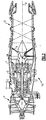
- Figure 2 schematically illustrates a gas turbine engine 10 which generally includes a fan section F, a compressor section C, a combustor section G, a turbine section T, an augmentor section A, and an exhaust duct assembly E.
- the compressor section C, combustor section G, and turbine section T are generally referred to as the core engine.
- An engine longitudinal axis X is centrally disposed and extends longitudinally through these sections.
- FIG. 3 schematically illustrates a High Pressure Turbine (HPT) section of the gas turbine engine 10 having a turbine disk assembly 12 within the turbine section T disposed along the engine longitudinal axis X.
- HPT High Pressure Turbine
- the HPT section includes a blade outer air seal assembly 16 with a rotor assembly 18 disposed between a forward stationary vane assembly 20 and an aft stationary vane assembly 22.
- Each vane assembly 20, 22 includes a plurality of vanes 24 circumferentially disposed around an inner vane support 26F, 26A.
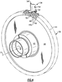
- the rotor assembly 18 includes a plurality of blades 34 circumferentially disposed around a rotor disk 36 ( Figure 4 ).
- the rotor disk 36 generally includes a hub 42, a rim 44, and a web 46 which extends therebetween.
- Each blade 34 generally includes an asymmetric attachment section 50, a platform section 52 and an airfoil section 54 along a longitudinal axis X.
- Each of the blades 34 is received within the rim 44 of the rotor disk 36 such that the asymmetric attachment section 50 is engaged therewith.
- the outer edge of each airfoil section 54 is a blade tip 54T which is adjacent the blade outer air seal assembly 16.
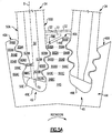
- the asymmetric attachment section 50 defines a first side 50A and a second side 50B.
- the first side 50A is the pressure side and the second side 50B is a suction side relative the rotational direction of the rotor disk 36.
- the first side 50A includes a multiple of lobes 60AA, 60AB, 60AC and a multiple of pockets 62AA, 62AB.
- the second side 50B includes a multiple of lobes 60BA, 60BB, 60BC and a multiple of pockets 62BA, 62BB.
- the multiple of lobes 60AA, 60AB, 60AC and the multiple of pockets 62AA, 62AB on the first side 50 are offset from the respective multiple of lobes 60BA, 60BB, 60BC and the multiple of pockets 62BA, 62BB on the second side 50B.
- the pocket 62AA is across from the lobe 60BA; the lobe 60AB is across from the lobe 62BA; the pocket 62AB is across from the lobe 60BB; and the lobe 60AC is across from the pocket 62BB relative to blade axis B.
- the asymmetrical fir-tree type attachment thereby provides tooth attachment lobes that are radially offset relative to the opposite side of the accepting set.
- the asymmetrical fir-tree type attachment may be manufactured through EDM, broaching, or grinding.
- the rim 44 defines an asymmetrical slot 49 to receive the asymmetric attachment section 50 of the respective blade 34.
- Each asymmetrical slot 49 defines a first side 49A and a second side 49B.
- the first side 49A includes a multiple of lobes 64AA, 64AB, 64AC and a multiple of pockets 66AA, 66AB, 66AC.
- the second side 49B includes a multiple of lobes 64BA, 64BB, 64BC and a multiple of pockets 66BA, 66BB, 66BC.
- the pocket 66AA is across from the lobe 64BA; the lobe 64AB is across from the pocket 66BA; the pocket 66AB is across from the lobe 64BB; the lobe 64AC is across from the pocket 66BB; and the pocket 66AC is across from the lobe 64BC relative to blade axis B.
- a rim section 44S is defined between each of two asymmetric slots 49.
- the rim section 44S includes the lobe 64BA across from the pocket 66AA; the pocket 66BA across from the lobe 64AB; the lobe 64BB across from the pocket 66AB; the pocket 66BB across from the lobe 64AC; and the lobe 64BC across from the pocket 66AC.
- This asymmetrical shape of the asymmetric attachment section 50 and the asymmetrical slot 49 may be formed through EDM, grinding, or broaching, which facilitates the flexibility to shape the fir-tree in a manner that can vary symmetry.
- the variation in symmetry increases the cross-sectional area of the rim section 44S between each blade asymmetrical slot 49 and the asymmetric attachment section 50 by offsetting the lobes.
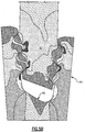
- the asymmetrical interface reduces shear stress and increase the overall capability of the blade 34 and the rotor disk 36.
- the reduced stress ( Figure 5B ) allows for reduced weight or an increase in performance by allowing the rotor system to increase in operational speed (RPM - revolutions per minute).
- RPM operational speed
- the asymmetrical interface of the asymmetric attachment section 50 and the asymmetrical slot 49 may generate a slight moment, the moment is readily compensated for by slight changes to the airfoil section 54.
- An angled distal end 50E ( Figure 5A ) of the asymmetric attachment section 50 relative to an angled distal end 49E of the asymmetric slot 49 provides a larger inlet area for cooling flow into an airflow cooling channel 70 of the blade 34.
- underplatform section hardware 72 illustrated schematically
- a damper and featherseal may be located adjacent an angled outer diameter 44E of the rims section 44S. That is, the underplatform section hardware 72 is located within the triangular area defined by the angled outer diameter 44E and the platform section 52.
Description
- The present invention relates to a gas turbine engine, and more particularly to a rotor blade attachment thereof.
- Gas turbine engines often include a multiple of rotor assemblies within a fan, compressor and turbine section. Each rotor assembly has a multitude of blades attached about a circumference of a rotor disk. Each of the blades is spaced a distance apart from adjacent blades to accommodate movement and expansion during operation. Each blade includes a root section that attaches to the rotor disk, a platform section, and an airfoil section that extends radially outwardly from the platform section.
- Gas turbine engine rotor blades are typically attached in a rotor disk rim through a fir-tree-type root attachment section. The blades are then locked into place with bolts, peening, locking wires, pins, keys, plates, or other locks. The blades need not fit too tightly in the rotor disk due to the centrifugal forces during engine operation. Some blade movement reduces the vibrational stresses produced by high-velocity airstreams between the blades.
- Referring to
Figure 1A , current rotor blade fir-tree-type root design attachments are symmetrical in shape and may vary from one lobe to four or more lobe tooth attachment designs. Although effective, this symmetry results in a reduced cross-sectional area between each blade which may limit Low Cycle Fatigue (LCF) and shear strength (P/A) (Figure 1B ) capability. - A rotor blade having the features of the preamble of
claim 1 is disclosed inUS-A-3045968 . Other blades are disclosed inGB-A-980656 US-A-2430140 . - A rotor blade for a gas turbine engine according to an aspect of the present invention is set forth in
claim 1. - The various features and advantages of this invention will become apparent to those skilled in the art from the following detailed description of the disclosed non-limiting embodiment. The drawings that accompany the detailed description can be briefly described as follows:
-
Figure 1A is an expanded front sectional view of a PRIOR ART rotor disk illustrating a symmetric attachment between two blades and the rotor disk; -
Figure 1B is an expanded front sectional view of a PRIOR ART rotor disk illustrating the stresses on the symmetric attachment between one blade and the rotor disk; -
Figure 2 is a schematic illustration of a gas turbine engine; -
Figure 3 is a general sectional diagrammatic view of a gas turbine engine HPT section of the engine ofFigure 2 ; -
Figure 4 is an expanded perspective view of the blade mounted to a rotor disk; -
Figure 5A is an expanded front sectional view of the rotor disk illustrating an asymmetric attachment between two blades and the rotor disk; and -
Figure 5B is an expanded front sectional view of a rotor disk illustrating the stresses on the asymmetric attachment between one blade and the rotor disk. -
Figure 2 schematically illustrates agas turbine engine 10 which generally includes a fan section F, a compressor section C, a combustor section G, a turbine section T, an augmentor section A, and an exhaust duct assembly E. The compressor section C, combustor section G, and turbine section T are generally referred to as the core engine. An engine longitudinal axis X is centrally disposed and extends longitudinally through these sections. Although a particular engine configuration is illustrated and described in the disclosed embodiment, other engines will also benefit herefrom. -
Figure 3 schematically illustrates a High Pressure Turbine (HPT) section of thegas turbine engine 10 having aturbine disk assembly 12 within the turbine section T disposed along the engine longitudinal axis X. It should be understood that a multiple of disks may be contained within each engine section and that although the HPT section is illustrated and described in the disclosed embodiment, other sections which have other blades such as fan blades, low pressure turbine blades, high pressure turbine blades, high pressure compressor blades and low pressure compressor blades will also benefit herefrom. - The HPT section includes a blade outer
air seal assembly 16 with arotor assembly 18 disposed between a forwardstationary vane assembly 20 and an aftstationary vane assembly 22. Eachvane assembly vanes 24 circumferentially disposed around aninner vane support - The
rotor assembly 18 includes a plurality ofblades 34 circumferentially disposed around a rotor disk 36 (Figure 4 ). Therotor disk 36 generally includes ahub 42, arim 44, and aweb 46 which extends therebetween. Eachblade 34 generally includes anasymmetric attachment section 50, aplatform section 52 and anairfoil section 54 along a longitudinal axis X. Each of theblades 34 is received within therim 44 of therotor disk 36 such that theasymmetric attachment section 50 is engaged therewith. The outer edge of eachairfoil section 54 is ablade tip 54T which is adjacent the blade outerair seal assembly 16. - Referring to
Figure 5A , theasymmetric attachment section 50 defines afirst side 50A and asecond side 50B. In one non-limiting embodiment, thefirst side 50A is the pressure side and thesecond side 50B is a suction side relative the rotational direction of therotor disk 36. Thefirst side 50A includes a multiple of lobes 60AA, 60AB, 60AC and a multiple of pockets 62AA, 62AB. Thesecond side 50B includes a multiple of lobes 60BA, 60BB, 60BC and a multiple of pockets 62BA, 62BB. The multiple of lobes 60AA, 60AB, 60AC and the multiple of pockets 62AA, 62AB on thefirst side 50 are offset from the respective multiple of lobes 60BA, 60BB, 60BC and the multiple of pockets 62BA, 62BB on thesecond side 50B. The pocket 62AA is across from the lobe 60BA; the lobe 60AB is across from the lobe 62BA; the pocket 62AB is across from the lobe 60BB; and the lobe 60AC is across from the pocket 62BB relative to blade axis B. The asymmetrical fir-tree type attachment thereby provides tooth attachment lobes that are radially offset relative to the opposite side of the accepting set. The asymmetrical fir-tree type attachment may be manufactured through EDM, broaching, or grinding. - The
rim 44 defines anasymmetrical slot 49 to receive theasymmetric attachment section 50 of therespective blade 34. Eachasymmetrical slot 49 defines afirst side 49A and asecond side 49B. Thefirst side 49A includes a multiple of lobes 64AA, 64AB, 64AC and a multiple of pockets 66AA, 66AB, 66AC. Thesecond side 49B includes a multiple of lobes 64BA, 64BB, 64BC and a multiple of pockets 66BA, 66BB, 66BC. The pocket 66AA is across from the lobe 64BA; the lobe 64AB is across from the pocket 66BA; the pocket 66AB is across from the lobe 64BB; the lobe 64AC is across from the pocket 66BB; and the pocket 66AC is across from the lobe 64BC relative to blade axis B. - A
rim section 44S is defined between each of twoasymmetric slots 49. Therim section 44S includes the lobe 64BA across from the pocket 66AA; the pocket 66BA across from the lobe 64AB; the lobe 64BB across from the pocket 66AB; the pocket 66BB across from the lobe 64AC; and the lobe 64BC across from the pocket 66AC. - This asymmetrical shape of the
asymmetric attachment section 50 and theasymmetrical slot 49 may be formed through EDM, grinding, or broaching, which facilitates the flexibility to shape the fir-tree in a manner that can vary symmetry. The variation in symmetry increases the cross-sectional area of therim section 44S between each bladeasymmetrical slot 49 and theasymmetric attachment section 50 by offsetting the lobes. - The asymmetrical interface reduces shear stress and increase the overall capability of the
blade 34 and therotor disk 36. The reduced stress (Figure 5B ) allows for reduced weight or an increase in performance by allowing the rotor system to increase in operational speed (RPM - revolutions per minute). Although the asymmetrical interface of theasymmetric attachment section 50 and theasymmetrical slot 49 may generate a slight moment, the moment is readily compensated for by slight changes to theairfoil section 54. - An angled
distal end 50E (Figure 5A ) of theasymmetric attachment section 50 relative to an angleddistal end 49E of theasymmetric slot 49 provides a larger inlet area for cooling flow into anairflow cooling channel 70 of theblade 34. - A shorter neck length below the
platform section 52 is also facilitated by theasymmetric attachment section 50 as underplatform section hardware 72 (illustrated schematically) such as a damper and featherseal may be located adjacent an angledouter diameter 44E of therims section 44S. That is, theunderplatform section hardware 72 is located within the triangular area defined by the angledouter diameter 44E and theplatform section 52. - It should be understood that relative positional terms such as "forward," "aft," "upper," "lower," "above," "below," and the like are with reference to the normal operational attitude of the vehicle and should not be considered otherwise limiting.
- It should be understood that like reference numerals identify corresponding or similar elements throughout the several drawings. It should also be understood that although a particular component arrangement is disclosed in the illustrated embodiment, other arrangements will benefit from the instant invention.
- Although particular step sequences are shown, described, and claimed, it should be understood that steps may be performed in any order, separated or combined unless otherwise indicated and will still benefit from the present invention.
- The foregoing description is exemplary rather than defined by the limitations within. Many modifications and variations of the present invention are possible in light of the above teachings. The disclosed embodiments of this invention have been disclosed, however, one of ordinary skill in the art would recognize that certain modifications would come within the scope of this invention. It is, therefore, to be understood that within the scope of the appended claims, the invention may be practiced otherwise than as specifically described. For that reason the following claims should be studied to determine the true scope and content of this invention.
Claims (11)
- A rotor blade (34) for a gas turbine engine comprising:
an asymmetric attachment section (50), which locates a lobe (60AB) opposite a pocket (62BA), characterised in that said asymmetric attachment section (50) extends from a platform section (52) and an airfoil section (54) extends from said platform section (52) opposite said asymmetric attachment (50); and in that:
the radially outermost lobe (60AA) of the attachment section (50) includes a surface facing away from an axis of rotation of the gas turbine engine, the surface interfacing directly with a radially directed surface of the blade (34). - The rotor blade as recited in claim 1, wherein said asymmetric attachment section (50) defines an angled distal end (50E).
- The rotor blade as recited in claim 1 or 2, wherein said asymmetric attachment section (50) defines a multiple of lobes (60AB ... 60BB) and a multiple of pockets (62AA ... 62BB), each of said multiple of lobes (60AB, 60AC) located on a first side (50A) of said asymmetric attachment section (50) opposite a pocket (62BA, 62BB) of said multiple of pockets on a second side (50B) of said asymmetric attachment section (50).
- The rotor blade as recited in claim 1 or 2, wherein said asymmetric attachment section (50) defines a multiple of lobes (60AB ... 60BB) and a multiple of pockets (62AA ... 62BB), each of said multiple of lobes (60BA, 60BB) located on a second side (50B) of said asymmetric attachment section (50) opposite a pocket (62AA, 62AB) of said multiple of pockets on a first side (50A) of said asymmetric attachment section (50).
- The rotor blade as recited in claim 1 or 2, wherein said asymmetric attachment section (50) defines a multiple of lobes (60AB ... 60BB) and a multiple of pockets (62AA ... 62BB), each of said multiple of lobes (60AB, 60AC) located on a first side (50A) of said asymmetric attachment section (50) opposite a pocket (62BA, 62BB) of said multiple of pockets on a second side (50B) of said asymmetric attachment section (50), each of said multiple of lobes (60BA, 60BB) located on said second side (50B) of said asymmetric attachment section (50) opposite a pocket (62AA, 62AB) of said multiple of pockets on said first side (50A) of said asymmetric attachment section (50).
- The rotor blade (34) as recited in claim 1, wherein said asymmetric attachment section (50) defines a multiple of first lobes (60AB, 60AC) and a multiple of first pockets (62AA, 62AB) on a first side (50A) and a multiple of second lobes (60BA, 60BB) and a multiple of second pockets (62BA, 62BB) on a second side (50B), at least one (60AB) of said multiple of first lobes located opposite a second pocket (62BA) and at least one (62AA) of said multiple of first pockets located opposite a second lobe (60BA).
- A rotor assembly for a gas turbine engine comprising:a rotor disk (36), the rotor disk comprising:a hub (42);a rim (44); anda web (46) which extends between said hub (42) and said rim (44), said rim (44) defines a multiple of asymmetric slots (49), each of said multiple of slots (49) comprises a lobe (64AB) opposite a pocket (66BA); wherein each of two of said multiple of asymmetric slots (49) defines a rim section (44S) therebetween, said rim section (44S) defining an angled outer diameter (44E);the rotor assembly further comprising a rotor blade (34) as recited in claim 1 received in each of the multiple of asymmetric slots (49); and wherein a triangular area is defined by the angled outer diameter (44E) and the platform section (52).
- The rotor assembly as recited in claim 7, wherein each of said multiple of asymmetric slots (49) defines an angled distal end (49E).
- The rotor assembly as recited in claim 7 or 8, wherein each of said multiple of asymmetric slots (49) defines a multiple of lobes (64AA ... 64BC) and a multiple of pockets (66AA ... 66BC), each of said multiple of lobes (64AB, 64AC) located on a first side (49A) of each of said multiple of asymmetric slots (49) opposite a pocket (66BA, 66BB) of said multiple of pockets on a second side (49B) of each of said multiple of asymmetric slots (49).
- The rotor assembly as recited in claim 7 or 8, wherein each of said multiple of asymmetric slots (49) defines a multiple of lobes (64AA ... 64BC) and a multiple of pockets (66AA ... 66BC), each of said multiple of lobes (64AB, 64AC) located on a second side (49B) of each of said multiple of asymmetric slots (49) opposite a pocket (66AA, 66AC) of said multiple of pockets on a first side (49B) of each of said multiple of asymmetric slots (49).
- The rotor assembly as recited in claim 7 or 8, wherein each of said multiple of asymmetric slots (49) defines a multiple of lobes (64AA ... 64BC) and a multiple of pockets (66AA ... 66BC), each of said multiple of lobes (64AB, 64AC) located on a first side (49A) of each of said multiple of asymmetric slots (49) opposite a pocket (66BA, 66BB) of said multiple of pockets on a second side (49B) of each of said multiple of asymmetric slots (49), each of said multiple of lobes (64BA ... 64BC) located on said second side (49B) of each of said multiple of asymmetric slots (49) opposite a pocket (66AA ... 66AC) of said multiple of pockets on said first side (49A) of each of said multiple of asymmetric slots (49).
Applications Claiming Priority (1)
| Application Number | Priority Date | Filing Date | Title |
|---|---|---|---|
| US12/103,673 US8221083B2 (en) | 2008-04-15 | 2008-04-15 | Asymmetrical rotor blade fir-tree attachment |
Publications (3)
| Publication Number | Publication Date |
|---|---|
| EP2110514A2 EP2110514A2 (en) | 2009-10-21 |
| EP2110514A3 EP2110514A3 (en) | 2013-03-06 |
| EP2110514B1 true EP2110514B1 (en) | 2018-05-02 |
Family
ID=40578242
Family Applications (1)
| Application Number | Title | Priority Date | Filing Date |
|---|---|---|---|
| EP09250722.7A Active EP2110514B1 (en) | 2008-04-15 | 2009-03-13 | Asymmetrical rotor blade fir tree attachment |
Country Status (2)
| Country | Link |
|---|---|
| US (1) | US8221083B2 (en) |
| EP (1) | EP2110514B1 (en) |
Families Citing this family (10)
| Publication number | Priority date | Publication date | Assignee | Title |
|---|---|---|---|---|
| US8734112B2 (en) * | 2010-11-30 | 2014-05-27 | United Technologies Corporation | Asymmetrical rotor blade slot attachment |
| US8694285B2 (en) | 2011-05-02 | 2014-04-08 | Hamilton Sundstrand Corporation | Turbine blade base load balancing |
| FR3018849B1 (en) * | 2014-03-24 | 2018-03-16 | Safran Aircraft Engines | REVOLUTION PIECE FOR A TURBOMACHINE ROTOR |
| EP3293362B1 (en) * | 2015-08-21 | 2020-07-22 | Mitsubishi Heavy Industries Compressor Corporation | Steam turbine |
| WO2017209752A1 (en) * | 2016-06-02 | 2017-12-07 | Siemens Aktiengesellschaft | Asymmetric attachment system for a turbine blade |
| US10577951B2 (en) * | 2016-11-30 | 2020-03-03 | Rolls-Royce North American Technologies Inc. | Gas turbine engine with dovetail connection having contoured root |
| GB201800732D0 (en) * | 2018-01-17 | 2018-02-28 | Rolls Royce Plc | Blade for a gas turbine engine |
| US10975714B2 (en) * | 2018-11-22 | 2021-04-13 | Pratt & Whitney Canada Corp. | Rotor assembly with blade sealing tab |
| DE102019207620A1 (en) | 2019-05-24 | 2020-11-26 | MTU Aero Engines AG | Blade with blade root contour with a straight line section provided in a concave contour section |
| US11608750B2 (en) * | 2021-01-12 | 2023-03-21 | Raytheon Technologies Corporation | Airfoil attachment for turbine rotor |
Citations (2)
| Publication number | Priority date | Publication date | Assignee | Title |
|---|---|---|---|---|
| GB2030657A (en) * | 1978-09-30 | 1980-04-10 | Rolls Royce | Blade for gas turbine engine |
| EP1464792A1 (en) * | 2003-03-26 | 2004-10-06 | ROLLS-ROYCE plc | A method of enabling cooling of the engaging firtree features of a turbine disk and associated blades |
Family Cites Families (76)
| Publication number | Priority date | Publication date | Assignee | Title |
|---|---|---|---|---|
| DE570754C (en) * | 1933-02-20 | Siemens Schuckertwerke Akt Ges | Blade attachment for steam or gas turbines | |
| FR892785A (en) * | 1941-06-12 | 1944-05-19 | Hermes Patentverwertungs Gmbh | Turbine fin and method for its attachment |
| US2430140A (en) * | 1945-04-06 | 1947-11-04 | Northrop Hendy Company | Turbine blade and mounting |
| FR989042A (en) * | 1949-04-19 | 1951-09-04 | Rateau Soc | Device for fixing the fins of axial generating or receiving turbomachines |
| US3045968A (en) * | 1959-12-10 | 1962-07-24 | Gen Motors Corp | Fir tree blade mount |
| CH408056A (en) * | 1962-11-23 | 1966-02-28 | Goerlitzer Maschinenbau Veb | Attachment of the rotor blades of centrifugal machines, especially for drum-type compressor rotors of gas turbines |
| US4102603A (en) | 1975-12-15 | 1978-07-25 | General Electric Company | Multiple section rotor disc |
| US4265595A (en) | 1979-01-02 | 1981-05-05 | General Electric Company | Turbomachinery blade retaining assembly |
| GB2043796B (en) | 1979-03-10 | 1983-04-20 | Rolls Royce | Bladed rotor for gas turbine engine |
| US4326835A (en) | 1979-10-29 | 1982-04-27 | General Motors Corporation | Blade platform seal for ceramic/metal rotor assembly |
| US4349318A (en) | 1980-01-04 | 1982-09-14 | Avco Corporation | Boltless blade retainer for a turbine wheel |
| US4418605A (en) | 1980-06-25 | 1983-12-06 | Pratt-Read Corporation | Keyboard for musical instrument |
| GB2097480B (en) * | 1981-04-29 | 1984-06-06 | Rolls Royce | Rotor blade fixing in circumferential slot |
| US4453890A (en) | 1981-06-18 | 1984-06-12 | General Electric Company | Blading system for a gas turbine engine |
| US4583914A (en) | 1982-06-14 | 1986-04-22 | United Technologies Corp. | Rotor blade for a rotary machine |
| US4507052A (en) | 1983-03-31 | 1985-03-26 | General Motors Corporation | End seal for turbine blade bases |
| US4523890A (en) | 1983-10-19 | 1985-06-18 | General Motors Corporation | End seal for turbine blade base |
| CA1204315A (en) | 1984-02-08 | 1986-05-13 | Pratt & Whitney Canada Inc. | Multiple cutter pass flank milling |
| US4659285A (en) | 1984-07-23 | 1987-04-21 | United Technologies Corporation | Turbine cover-seal assembly |
| US4863352A (en) | 1984-11-02 | 1989-09-05 | General Electric Company | Blade carrying means |
| US4895490A (en) | 1988-11-28 | 1990-01-23 | The United States Of America As Represented By The Secretary Of The Air Force | Internal blade retention system for rotary engines |
| US4872810A (en) | 1988-12-14 | 1989-10-10 | United Technologies Corporation | Turbine rotor retention system |
| US4890981A (en) | 1988-12-30 | 1990-01-02 | General Electric Company | Boltless rotor blade retainer |
| US5039278A (en) | 1989-04-11 | 1991-08-13 | General Electric Company | Power turbine ventilation system |
| US5030063A (en) | 1990-02-08 | 1991-07-09 | General Motors Corporation | Turbomachine rotor |
| US5067876A (en) | 1990-03-29 | 1991-11-26 | General Electric Company | Gas turbine bladed disk |
| US5134843A (en) | 1990-10-10 | 1992-08-04 | General Electric Company | Telemetry carrier ring and support |
| US5156528A (en) * | 1991-04-19 | 1992-10-20 | General Electric Company | Vibration damping of gas turbine engine buckets |
| US5259728A (en) | 1992-05-08 | 1993-11-09 | General Electric Company | Bladed disk assembly |
| US5256035A (en) | 1992-06-01 | 1993-10-26 | United Technologies Corporation | Rotor blade retention and sealing construction |
| US5282720A (en) | 1992-09-15 | 1994-02-01 | General Electric Company | Fan blade retainer |
| US5281098A (en) | 1992-10-28 | 1994-01-25 | General Electric Company | Single ring blade retaining assembly |
| GB9223593D0 (en) | 1992-11-11 | 1992-12-23 | Rolls Royce Plc | Gas turbine engine fan blade assembly |
| US5310318A (en) | 1993-07-21 | 1994-05-10 | General Electric Company | Asymmetric axial dovetail and rotor disk |
| US5368444A (en) | 1993-08-30 | 1994-11-29 | General Electric Company | Anti-fretting blade retention means |
| GB9412963D0 (en) | 1994-06-28 | 1994-09-28 | Rolls Royce Plc | Gas turbine engine fan blade assembly |
| US5622475A (en) | 1994-08-30 | 1997-04-22 | General Electric Company | Double rabbet rotor blade retention assembly |
| GB2294732A (en) | 1994-11-05 | 1996-05-08 | Rolls Royce Plc | Integral disc seal for turbomachine |
| US5518369A (en) | 1994-12-15 | 1996-05-21 | Pratt & Whitney Canada Inc. | Gas turbine blade retention |
| GB9517369D0 (en) | 1995-08-24 | 1995-10-25 | Rolls Royce Plc | Bladed rotor |
| US5630703A (en) | 1995-12-15 | 1997-05-20 | General Electric Company | Rotor disk post cooling system |
| GB2313162B (en) | 1996-05-17 | 2000-02-16 | Rolls Royce Plc | Bladed rotor |
| GB9615394D0 (en) | 1996-07-23 | 1996-09-04 | Rolls Royce Plc | Gas turbine engine rotor disc with cooling fluid passage |
| GB9615826D0 (en) | 1996-07-27 | 1996-09-11 | Rolls Royce Plc | Gas turbine engine fan blade retention |
| US6010304A (en) | 1997-10-29 | 2000-01-04 | General Electric Company | Blade retention system for a variable rotor blade |
| US6077035A (en) | 1998-03-27 | 2000-06-20 | Pratt & Whitney Canada Corp. | Deflector for controlling entry of cooling air leakage into the gaspath of a gas turbine engine |
| US5984639A (en) | 1998-07-09 | 1999-11-16 | Pratt & Whitney Canada Inc. | Blade retention apparatus for gas turbine rotor |
| US6109877A (en) | 1998-11-23 | 2000-08-29 | Pratt & Whitney Canada Corp. | Turbine blade-to-disk retention device |
| US6176677B1 (en) | 1999-05-19 | 2001-01-23 | Pratt & Whitney Canada Corp. | Device for controlling air flow in a turbine blade |
| US6413041B1 (en) | 2000-08-02 | 2002-07-02 | Siemens Westinghouse Power Corporation | Method and apparatus for closing holes in superalloy gas turbine blades |
| US6457942B1 (en) | 2000-11-27 | 2002-10-01 | General Electric Company | Fan blade retainer |
| US6481971B1 (en) | 2000-11-27 | 2002-11-19 | General Electric Company | Blade spacer |
| US6464453B2 (en) | 2000-12-04 | 2002-10-15 | General Electric Company | Turbine interstage sealing ring |
| US6578351B1 (en) | 2001-08-29 | 2003-06-17 | Pratt & Whitney Canada Corp. | APU core compressor providing cooler air supply |
| US6533550B1 (en) | 2001-10-23 | 2003-03-18 | Pratt & Whitney Canada Corp. | Blade retention |
| US6735956B2 (en) | 2001-10-26 | 2004-05-18 | Pratt & Whitney Canada Corp. | High pressure turbine blade cooling scoop |
| US6733233B2 (en) | 2002-04-26 | 2004-05-11 | Pratt & Whitney Canada Corp. | Attachment of a ceramic shroud in a metal housing |
| US6837686B2 (en) | 2002-09-27 | 2005-01-04 | Pratt & Whitney Canada Corp. | Blade retention scheme using a retention tab |
| US6884028B2 (en) | 2002-09-30 | 2005-04-26 | General Electric Company | Turbomachinery blade retention system |
| US7284958B2 (en) | 2003-03-22 | 2007-10-23 | Allison Advanced Development Company | Separable blade platform |
| US6976826B2 (en) | 2003-05-29 | 2005-12-20 | Pratt & Whitney Canada Corp. | Turbine blade dimple |
| US6974306B2 (en) | 2003-07-28 | 2005-12-13 | Pratt & Whitney Canada Corp. | Blade inlet cooling flow deflector apparatus and method |
| GB2405183A (en) | 2003-08-21 | 2005-02-23 | Rolls Royce Plc | Ring and channel arrangement for joining components |
| US6932575B2 (en) | 2003-10-08 | 2005-08-23 | United Technologies Corporation | Blade damper |
| DE10348198A1 (en) | 2003-10-16 | 2005-05-12 | Rolls Royce Deutschland | Scoop restraint |
| US7001150B2 (en) | 2003-10-16 | 2006-02-21 | Pratt & Whitney Canada Corp. | Hollow turbine blade stiffening |
| DE102004015301A1 (en) | 2004-03-29 | 2005-10-13 | Mtu Aero Engines Gmbh | Blade, in particular for a gas turbine |
| US7252481B2 (en) | 2004-05-14 | 2007-08-07 | Pratt & Whitney Canada Corp. | Natural frequency tuning of gas turbine engine blades |
| US7153102B2 (en) | 2004-05-14 | 2006-12-26 | Pratt & Whitney Canada Corp. | Bladed disk fixing undercut |
| US7156621B2 (en) | 2004-05-14 | 2007-01-02 | Pratt & Whitney Canada Corp. | Blade fixing relief mismatch |
| US7238008B2 (en) | 2004-05-28 | 2007-07-03 | General Electric Company | Turbine blade retainer seal |
| US7192245B2 (en) | 2004-12-03 | 2007-03-20 | Pratt & Whitney Canada Corp. | Rotor assembly with cooling air deflectors and method |
| US7189056B2 (en) | 2005-05-31 | 2007-03-13 | Pratt & Whitney Canada Corp. | Blade and disk radial pre-swirlers |
| US7189055B2 (en) | 2005-05-31 | 2007-03-13 | Pratt & Whitney Canada Corp. | Coverplate deflectors for redirecting a fluid flow |
| US7244104B2 (en) | 2005-05-31 | 2007-07-17 | Pratt & Whitney Canada Corp. | Deflectors for controlling entry of fluid leakage into the working fluid flowpath of a gas turbine engine |
| US7296969B2 (en) | 2005-10-12 | 2007-11-20 | Hamilton Sundstrand Corporation | Propeller pitch change system |
-
2008
- 2008-04-15 US US12/103,673 patent/US8221083B2/en active Active
-
2009
- 2009-03-13 EP EP09250722.7A patent/EP2110514B1/en active Active
Patent Citations (2)
| Publication number | Priority date | Publication date | Assignee | Title |
|---|---|---|---|---|
| GB2030657A (en) * | 1978-09-30 | 1980-04-10 | Rolls Royce | Blade for gas turbine engine |
| EP1464792A1 (en) * | 2003-03-26 | 2004-10-06 | ROLLS-ROYCE plc | A method of enabling cooling of the engaging firtree features of a turbine disk and associated blades |
Also Published As
| Publication number | Publication date |
|---|---|
| US8221083B2 (en) | 2012-07-17 |
| EP2110514A2 (en) | 2009-10-21 |
| EP2110514A3 (en) | 2013-03-06 |
| US20090257877A1 (en) | 2009-10-15 |
Similar Documents
| Publication | Publication Date | Title |
|---|---|---|
| EP2110514B1 (en) | Asymmetrical rotor blade fir tree attachment | |
| EP3187687B1 (en) | Midspan shrouded turbine rotor blades | |
| EP2372088B1 (en) | Turbofan flow path trenches | |
| EP2093384B2 (en) | Filter system for blade outer air seal | |
| EP2386723B1 (en) | Variable area turbine vane arrangement | |
| US10344601B2 (en) | Contoured flowpath surface | |
| EP2959108B1 (en) | Gas turbine engine having a mistuned stage | |
| EP1890008B1 (en) | Rotor blade | |
| EP1939411A2 (en) | Cantilevered nozzle with crowned flange to improve outer band low cycle fatigue | |
| EP2484867B1 (en) | Rotating component of a turbine engine | |
| US20170183971A1 (en) | Tip shrouded turbine rotor blades | |
| US10294805B2 (en) | Gas turbine engine integrally bladed rotor with asymmetrical trench fillets | |
| EP2984290B1 (en) | Integrally bladed rotor | |
| EP2971570B1 (en) | Fan blade dovetail and spacer | |
| EP3208467B1 (en) | Compressor rotor for supersonic flutter and/or resonant stress mitigation | |
| EP2458154B1 (en) | Rotor disk with asymmetrical rotor blade slot, corresponding rotor disk assembly and manufacturing method | |
| EP3596312B1 (en) | Snubbered blades with improved flutter resistance | |
| US9828864B2 (en) | Fan blade tall dovetail for individually bladed rotors | |
| CN110612382B (en) | Shrouded blade with improved flutter resistance |
Legal Events
| Date | Code | Title | Description |
|---|---|---|---|
| PUAI | Public reference made under article 153(3) epc to a published international application that has entered the european phase |
Free format text: ORIGINAL CODE: 0009012 |
|
| AK | Designated contracting states |
Kind code of ref document: A2 Designated state(s): AT BE BG CH CY CZ DE DK EE ES FI FR GB GR HR HU IE IS IT LI LT LU LV MC MK MT NL NO PL PT RO SE SI SK TR |
|
| AX | Request for extension of the european patent |
Extension state: AL BA RS |
|
| PUAL | Search report despatched |
Free format text: ORIGINAL CODE: 0009013 |
|
| AK | Designated contracting states |
Kind code of ref document: A3 Designated state(s): AT BE BG CH CY CZ DE DK EE ES FI FR GB GR HR HU IE IS IT LI LT LU LV MC MK MT NL NO PL PT RO SE SI SK TR |
|
| AX | Request for extension of the european patent |
Extension state: AL BA RS |
|
| RIC1 | Information provided on ipc code assigned before grant |
Ipc: F01D 5/30 20060101AFI20130125BHEP |
|
| 17P | Request for examination filed |
Effective date: 20130903 |
|
| RBV | Designated contracting states (corrected) |
Designated state(s): AT BE BG CH CY CZ DE DK EE ES FI FR GB GR HR HU IE IS IT LI LT LU LV MC MK MT NL NO PL PT RO SE SI SK TR |
|
| AKX | Designation fees paid |
Designated state(s): DE GB |
|
| RAP1 | Party data changed (applicant data changed or rights of an application transferred) |
Owner name: UNITED TECHNOLOGIES CORPORATION |
|
| 17Q | First examination report despatched |
Effective date: 20161130 |
|
| GRAP | Despatch of communication of intention to grant a patent |
Free format text: ORIGINAL CODE: EPIDOSNIGR1 |
|
| INTG | Intention to grant announced |
Effective date: 20171005 |
|
| GRAS | Grant fee paid |
Free format text: ORIGINAL CODE: EPIDOSNIGR3 |
|
| GRAA | (expected) grant |
Free format text: ORIGINAL CODE: 0009210 |
|
| AK | Designated contracting states |
Kind code of ref document: B1 Designated state(s): DE GB |
|
| REG | Reference to a national code |
Ref country code: GB Ref legal event code: FG4D |
|
| REG | Reference to a national code |
Ref country code: DE Ref legal event code: R096 Ref document number: 602009052070 Country of ref document: DE |
|
| REG | Reference to a national code |
Ref country code: DE Ref legal event code: R097 Ref document number: 602009052070 Country of ref document: DE |
|
| PLBE | No opposition filed within time limit |
Free format text: ORIGINAL CODE: 0009261 |
|
| STAA | Information on the status of an ep patent application or granted ep patent |
Free format text: STATUS: NO OPPOSITION FILED WITHIN TIME LIMIT |
|
| 26N | No opposition filed |
Effective date: 20190205 |
|
| REG | Reference to a national code |
Ref country code: DE Ref legal event code: R081 Ref document number: 602009052070 Country of ref document: DE Owner name: RAYTHEON TECHNOLOGIES CORPORATION (N.D.GES.D.S, US Free format text: FORMER OWNER: UNITED TECHNOLOGIES CORPORATION, FARMINGTON, CONN., US |
|
| PGFP | Annual fee paid to national office [announced via postgrant information from national office to epo] |
Ref country code: GB Payment date: 20230222 Year of fee payment: 15 Ref country code: DE Payment date: 20230221 Year of fee payment: 15 |
|
| P01 | Opt-out of the competence of the unified patent court (upc) registered |
Effective date: 20230519 |