EP3211027B1 - Transfer film with metallic layer and method for its production - Google Patents
Transfer film with metallic layer and method for its production Download PDFInfo
- Publication number
- EP3211027B1 EP3211027B1 EP16000472.7A EP16000472A EP3211027B1 EP 3211027 B1 EP3211027 B1 EP 3211027B1 EP 16000472 A EP16000472 A EP 16000472A EP 3211027 B1 EP3211027 B1 EP 3211027B1
- Authority
- EP
- European Patent Office
- Prior art keywords
- layer
- transfer film
- metallic layer
- lacquer
- metallic
- Prior art date
- Legal status (The legal status is an assumption and is not a legal conclusion. Google has not performed a legal analysis and makes no representation as to the accuracy of the status listed.)
- Active
Links
- 238000000034 method Methods 0.000 title claims description 11
- 238000004519 manufacturing process Methods 0.000 title claims description 6
- 239000010410 layer Substances 0.000 claims description 137
- 239000004922 lacquer Substances 0.000 claims description 30
- QGZKDVFQNNGYKY-UHFFFAOYSA-N Ammonia Chemical compound N QGZKDVFQNNGYKY-UHFFFAOYSA-N 0.000 claims description 8
- 239000012790 adhesive layer Substances 0.000 claims description 6
- 229910021529 ammonia Inorganic materials 0.000 claims description 4
- 229910052802 copper Inorganic materials 0.000 claims description 4
- 229920006228 ethylene acrylate copolymer Polymers 0.000 claims description 4
- 238000007639 printing Methods 0.000 claims description 4
- 229910052782 aluminium Inorganic materials 0.000 claims description 3
- 230000003287 optical effect Effects 0.000 claims description 3
- 239000002904 solvent Substances 0.000 claims description 3
- 150000001252 acrylic acid derivatives Chemical class 0.000 claims description 2
- 229910052804 chromium Inorganic materials 0.000 claims description 2
- 239000006185 dispersion Substances 0.000 claims description 2
- 229910052737 gold Inorganic materials 0.000 claims description 2
- 229910052763 palladium Inorganic materials 0.000 claims description 2
- 229910052697 platinum Inorganic materials 0.000 claims description 2
- 229910052709 silver Inorganic materials 0.000 claims description 2
- 229910052719 titanium Inorganic materials 0.000 claims description 2
- 229910052725 zinc Inorganic materials 0.000 claims description 2
- 229920001577 copolymer Polymers 0.000 claims 1
- XLYOFNOQVPJJNP-UHFFFAOYSA-N water Substances O XLYOFNOQVPJJNP-UHFFFAOYSA-N 0.000 claims 1
- 239000000758 substrate Substances 0.000 description 24
- 239000010949 copper Substances 0.000 description 18
- 238000000576 coating method Methods 0.000 description 10
- 239000002318 adhesion promoter Substances 0.000 description 7
- -1 MOPP Substances 0.000 description 6
- 239000000853 adhesive Substances 0.000 description 6
- 239000011248 coating agent Substances 0.000 description 6
- 239000011888 foil Substances 0.000 description 6
- 230000001070 adhesive effect Effects 0.000 description 5
- 239000003973 paint Substances 0.000 description 5
- 229910052751 metal Inorganic materials 0.000 description 3
- 239000002184 metal Substances 0.000 description 3
- 238000005240 physical vapour deposition Methods 0.000 description 3
- 229920000139 polyethylene terephthalate Polymers 0.000 description 3
- 239000005020 polyethylene terephthalate Substances 0.000 description 3
- 239000002243 precursor Substances 0.000 description 3
- XKRFYHLGVUSROY-UHFFFAOYSA-N Argon Chemical compound [Ar] XKRFYHLGVUSROY-UHFFFAOYSA-N 0.000 description 2
- RYGMFSIKBFXOCR-UHFFFAOYSA-N Copper Chemical compound [Cu] RYGMFSIKBFXOCR-UHFFFAOYSA-N 0.000 description 2
- 229910002091 carbon monoxide Inorganic materials 0.000 description 2
- 239000007795 chemical reaction product Substances 0.000 description 2
- 238000005566 electron beam evaporation Methods 0.000 description 2
- 229920000840 ethylene tetrafluoroethylene copolymer Polymers 0.000 description 2
- 239000012943 hotmelt Substances 0.000 description 2
- 239000000463 material Substances 0.000 description 2
- VNWKTOKETHGBQD-UHFFFAOYSA-N methane Chemical compound C VNWKTOKETHGBQD-UHFFFAOYSA-N 0.000 description 2
- 239000004810 polytetrafluoroethylene Substances 0.000 description 2
- 229920002620 polyvinyl fluoride Polymers 0.000 description 2
- 238000004544 sputter deposition Methods 0.000 description 2
- 238000002207 thermal evaporation Methods 0.000 description 2
- 239000002033 PVDF binder Substances 0.000 description 1
- 239000004696 Poly ether ether ketone Substances 0.000 description 1
- 239000004698 Polyethylene Substances 0.000 description 1
- 102100037681 Protein FEV Human genes 0.000 description 1
- 101710198166 Protein FEV Proteins 0.000 description 1
- 239000002253 acid Substances 0.000 description 1
- 150000007513 acids Chemical class 0.000 description 1
- 239000002313 adhesive film Substances 0.000 description 1
- XAGFODPZIPBFFR-UHFFFAOYSA-N aluminium Chemical compound [Al] XAGFODPZIPBFFR-UHFFFAOYSA-N 0.000 description 1
- 229910052786 argon Inorganic materials 0.000 description 1
- QVGXLLKOCUKJST-UHFFFAOYSA-N atomic oxygen Chemical compound [O] QVGXLLKOCUKJST-UHFFFAOYSA-N 0.000 description 1
- JUPQTSLXMOCDHR-UHFFFAOYSA-N benzene-1,4-diol;bis(4-fluorophenyl)methanone Chemical compound OC1=CC=C(O)C=C1.C1=CC(F)=CC=C1C(=O)C1=CC=C(F)C=C1 JUPQTSLXMOCDHR-UHFFFAOYSA-N 0.000 description 1
- 230000001680 brushing effect Effects 0.000 description 1
- 239000012159 carrier gas Substances 0.000 description 1
- 239000002131 composite material Substances 0.000 description 1
- 150000001875 compounds Chemical class 0.000 description 1
- 230000007547 defect Effects 0.000 description 1
- 230000001419 dependent effect Effects 0.000 description 1
- 230000000694 effects Effects 0.000 description 1
- 238000010894 electron beam technology Methods 0.000 description 1
- QHSJIZLJUFMIFP-UHFFFAOYSA-N ethene;1,1,2,2-tetrafluoroethene Chemical group C=C.FC(F)=C(F)F QHSJIZLJUFMIFP-UHFFFAOYSA-N 0.000 description 1
- 229920006129 ethylene fluorinated ethylene propylene Polymers 0.000 description 1
- 239000004744 fabric Substances 0.000 description 1
- KTWOOEGAPBSYNW-UHFFFAOYSA-N ferrocene Chemical compound [Fe+2].C=1C=C[CH-]C=1.C=1C=C[CH-]C=1 KTWOOEGAPBSYNW-UHFFFAOYSA-N 0.000 description 1
- 229920002457 flexible plastic Polymers 0.000 description 1
- 229920002313 fluoropolymer Polymers 0.000 description 1
- 239000004811 fluoropolymer Substances 0.000 description 1
- 239000007789 gas Substances 0.000 description 1
- 230000003993 interaction Effects 0.000 description 1
- 238000010884 ion-beam technique Methods 0.000 description 1
- 150000002500 ions Chemical class 0.000 description 1
- 239000012939 laminating adhesive Substances 0.000 description 1
- 238000003475 lamination Methods 0.000 description 1
- 229910044991 metal oxide Inorganic materials 0.000 description 1
- 150000004706 metal oxides Chemical class 0.000 description 1
- 150000002739 metals Chemical class 0.000 description 1
- 239000000203 mixture Substances 0.000 description 1
- 125000002524 organometallic group Chemical group 0.000 description 1
- 239000001301 oxygen Substances 0.000 description 1
- 229910052760 oxygen Inorganic materials 0.000 description 1
- 239000002985 plastic film Substances 0.000 description 1
- 229920001643 poly(ether ketone) Polymers 0.000 description 1
- 229920006260 polyaryletherketone Polymers 0.000 description 1
- 229920002530 polyetherether ketone Polymers 0.000 description 1
- 229920000573 polyethylene Polymers 0.000 description 1
- 229940058401 polytetrafluoroethylene Drugs 0.000 description 1
- 229920001343 polytetrafluoroethylene Polymers 0.000 description 1
- 238000007650 screen-printing Methods 0.000 description 1
- 239000004065 semiconductor Substances 0.000 description 1
- 150000004756 silanes Chemical class 0.000 description 1
- 238000005507 spraying Methods 0.000 description 1
- 239000000126 substance Substances 0.000 description 1
- JLTRXTDYQLMHGR-UHFFFAOYSA-N trimethylaluminium Chemical compound C[Al](C)C JLTRXTDYQLMHGR-UHFFFAOYSA-N 0.000 description 1
- 238000001771 vacuum deposition Methods 0.000 description 1
Images
Classifications
-
- B—PERFORMING OPERATIONS; TRANSPORTING
- B32—LAYERED PRODUCTS
- B32B—LAYERED PRODUCTS, i.e. PRODUCTS BUILT-UP OF STRATA OF FLAT OR NON-FLAT, e.g. CELLULAR OR HONEYCOMB, FORM
- B32B38/00—Ancillary operations in connection with laminating processes
- B32B38/10—Removing layers, or parts of layers, mechanically or chemically
-
- B—PERFORMING OPERATIONS; TRANSPORTING
- B42—BOOKBINDING; ALBUMS; FILES; SPECIAL PRINTED MATTER
- B42D—BOOKS; BOOK COVERS; LOOSE LEAVES; PRINTED MATTER CHARACTERISED BY IDENTIFICATION OR SECURITY FEATURES; PRINTED MATTER OF SPECIAL FORMAT OR STYLE NOT OTHERWISE PROVIDED FOR; DEVICES FOR USE THEREWITH AND NOT OTHERWISE PROVIDED FOR; MOVABLE-STRIP WRITING OR READING APPARATUS
- B42D25/00—Information-bearing cards or sheet-like structures characterised by identification or security features; Manufacture thereof
- B42D25/30—Identification or security features, e.g. for preventing forgery
- B42D25/355—Security threads
-
- B—PERFORMING OPERATIONS; TRANSPORTING
- B42—BOOKBINDING; ALBUMS; FILES; SPECIAL PRINTED MATTER
- B42D—BOOKS; BOOK COVERS; LOOSE LEAVES; PRINTED MATTER CHARACTERISED BY IDENTIFICATION OR SECURITY FEATURES; PRINTED MATTER OF SPECIAL FORMAT OR STYLE NOT OTHERWISE PROVIDED FOR; DEVICES FOR USE THEREWITH AND NOT OTHERWISE PROVIDED FOR; MOVABLE-STRIP WRITING OR READING APPARATUS
- B42D25/00—Information-bearing cards or sheet-like structures characterised by identification or security features; Manufacture thereof
- B42D25/30—Identification or security features, e.g. for preventing forgery
- B42D25/36—Identification or security features, e.g. for preventing forgery comprising special materials
- B42D25/373—Metallic materials
-
- B—PERFORMING OPERATIONS; TRANSPORTING
- B42—BOOKBINDING; ALBUMS; FILES; SPECIAL PRINTED MATTER
- B42D—BOOKS; BOOK COVERS; LOOSE LEAVES; PRINTED MATTER CHARACTERISED BY IDENTIFICATION OR SECURITY FEATURES; PRINTED MATTER OF SPECIAL FORMAT OR STYLE NOT OTHERWISE PROVIDED FOR; DEVICES FOR USE THEREWITH AND NOT OTHERWISE PROVIDED FOR; MOVABLE-STRIP WRITING OR READING APPARATUS
- B42D25/00—Information-bearing cards or sheet-like structures characterised by identification or security features; Manufacture thereof
- B42D25/40—Manufacture
- B42D25/45—Associating two or more layers
- B42D25/465—Associating two or more layers using chemicals or adhesives
- B42D25/47—Associating two or more layers using chemicals or adhesives using adhesives
-
- C—CHEMISTRY; METALLURGY
- C08—ORGANIC MACROMOLECULAR COMPOUNDS; THEIR PREPARATION OR CHEMICAL WORKING-UP; COMPOSITIONS BASED THEREON
- C08J—WORKING-UP; GENERAL PROCESSES OF COMPOUNDING; AFTER-TREATMENT NOT COVERED BY SUBCLASSES C08B, C08C, C08F, C08G or C08H
- C08J7/00—Chemical treatment or coating of shaped articles made of macromolecular substances
- C08J7/04—Coating
- C08J7/042—Coating with two or more layers, where at least one layer of a composition contains a polymer binder
- C08J7/0423—Coating with two or more layers, where at least one layer of a composition contains a polymer binder with at least one layer of inorganic material and at least one layer of a composition containing a polymer binder
-
- C—CHEMISTRY; METALLURGY
- C08—ORGANIC MACROMOLECULAR COMPOUNDS; THEIR PREPARATION OR CHEMICAL WORKING-UP; COMPOSITIONS BASED THEREON
- C08J—WORKING-UP; GENERAL PROCESSES OF COMPOUNDING; AFTER-TREATMENT NOT COVERED BY SUBCLASSES C08B, C08C, C08F, C08G or C08H
- C08J7/00—Chemical treatment or coating of shaped articles made of macromolecular substances
- C08J7/04—Coating
- C08J7/043—Improving the adhesiveness of the coatings per se, e.g. forming primers
-
- B—PERFORMING OPERATIONS; TRANSPORTING
- B32—LAYERED PRODUCTS
- B32B—LAYERED PRODUCTS, i.e. PRODUCTS BUILT-UP OF STRATA OF FLAT OR NON-FLAT, e.g. CELLULAR OR HONEYCOMB, FORM
- B32B2307/00—Properties of the layers or laminate
- B32B2307/20—Properties of the layers or laminate having particular electrical or magnetic properties, e.g. piezoelectric
- B32B2307/202—Conductive
-
- B—PERFORMING OPERATIONS; TRANSPORTING
- B32—LAYERED PRODUCTS
- B32B—LAYERED PRODUCTS, i.e. PRODUCTS BUILT-UP OF STRATA OF FLAT OR NON-FLAT, e.g. CELLULAR OR HONEYCOMB, FORM
- B32B2311/00—Metals, their alloys or their compounds
- B32B2311/12—Copper
-
- B—PERFORMING OPERATIONS; TRANSPORTING
- B32—LAYERED PRODUCTS
- B32B—LAYERED PRODUCTS, i.e. PRODUCTS BUILT-UP OF STRATA OF FLAT OR NON-FLAT, e.g. CELLULAR OR HONEYCOMB, FORM
- B32B37/00—Methods or apparatus for laminating, e.g. by curing or by ultrasonic bonding
- B32B37/02—Methods or apparatus for laminating, e.g. by curing or by ultrasonic bonding characterised by a sequence of laminating steps, e.g. by adding new layers at consecutive laminating stations
- B32B37/025—Transfer laminating
-
- C—CHEMISTRY; METALLURGY
- C08—ORGANIC MACROMOLECULAR COMPOUNDS; THEIR PREPARATION OR CHEMICAL WORKING-UP; COMPOSITIONS BASED THEREON
- C08J—WORKING-UP; GENERAL PROCESSES OF COMPOUNDING; AFTER-TREATMENT NOT COVERED BY SUBCLASSES C08B, C08C, C08F, C08G or C08H
- C08J2427/00—Characterised by the use of homopolymers or copolymers of compounds having one or more unsaturated aliphatic radicals, each having only one carbon-to-carbon double bond, and at least one being terminated by a halogen; Derivatives of such polymers
- C08J2427/02—Characterised by the use of homopolymers or copolymers of compounds having one or more unsaturated aliphatic radicals, each having only one carbon-to-carbon double bond, and at least one being terminated by a halogen; Derivatives of such polymers not modified by chemical after-treatment
- C08J2427/04—Characterised by the use of homopolymers or copolymers of compounds having one or more unsaturated aliphatic radicals, each having only one carbon-to-carbon double bond, and at least one being terminated by a halogen; Derivatives of such polymers not modified by chemical after-treatment containing chlorine atoms
- C08J2427/06—Homopolymers or copolymers of vinyl chloride
-
- C—CHEMISTRY; METALLURGY
- C08—ORGANIC MACROMOLECULAR COMPOUNDS; THEIR PREPARATION OR CHEMICAL WORKING-UP; COMPOSITIONS BASED THEREON
- C08J—WORKING-UP; GENERAL PROCESSES OF COMPOUNDING; AFTER-TREATMENT NOT COVERED BY SUBCLASSES C08B, C08C, C08F, C08G or C08H
- C08J2433/00—Characterised by the use of homopolymers or copolymers of compounds having one or more unsaturated aliphatic radicals, each having only one carbon-to-carbon double bond, and only one being terminated by only one carboxyl radical, or of salts, anhydrides, esters, amides, imides, or nitriles thereof; Derivatives of such polymers
- C08J2433/04—Characterised by the use of homopolymers or copolymers of compounds having one or more unsaturated aliphatic radicals, each having only one carbon-to-carbon double bond, and only one being terminated by only one carboxyl radical, or of salts, anhydrides, esters, amides, imides, or nitriles thereof; Derivatives of such polymers esters
- C08J2433/06—Characterised by the use of homopolymers or copolymers of compounds having one or more unsaturated aliphatic radicals, each having only one carbon-to-carbon double bond, and only one being terminated by only one carboxyl radical, or of salts, anhydrides, esters, amides, imides, or nitriles thereof; Derivatives of such polymers esters of esters containing only carbon, hydrogen, and oxygen, the oxygen atom being present only as part of the carboxyl radical
- C08J2433/08—Homopolymers or copolymers of acrylic acid esters
-
- C—CHEMISTRY; METALLURGY
- C08—ORGANIC MACROMOLECULAR COMPOUNDS; THEIR PREPARATION OR CHEMICAL WORKING-UP; COMPOSITIONS BASED THEREON
- C08J—WORKING-UP; GENERAL PROCESSES OF COMPOUNDING; AFTER-TREATMENT NOT COVERED BY SUBCLASSES C08B, C08C, C08F, C08G or C08H
- C08J2433/00—Characterised by the use of homopolymers or copolymers of compounds having one or more unsaturated aliphatic radicals, each having only one carbon-to-carbon double bond, and only one being terminated by only one carboxyl radical, or of salts, anhydrides, esters, amides, imides, or nitriles thereof; Derivatives of such polymers
- C08J2433/04—Characterised by the use of homopolymers or copolymers of compounds having one or more unsaturated aliphatic radicals, each having only one carbon-to-carbon double bond, and only one being terminated by only one carboxyl radical, or of salts, anhydrides, esters, amides, imides, or nitriles thereof; Derivatives of such polymers esters
- C08J2433/06—Characterised by the use of homopolymers or copolymers of compounds having one or more unsaturated aliphatic radicals, each having only one carbon-to-carbon double bond, and only one being terminated by only one carboxyl radical, or of salts, anhydrides, esters, amides, imides, or nitriles thereof; Derivatives of such polymers esters of esters containing only carbon, hydrogen, and oxygen, the oxygen atom being present only as part of the carboxyl radical
- C08J2433/10—Homopolymers or copolymers of methacrylic acid esters
- C08J2433/12—Homopolymers or copolymers of methyl methacrylate
Definitions
- the invention relates to a transfer film according to the preamble of claim 1.
- Transfer foils are used, for example, for the transfer of security elements to documents of value, such as banknotes, to security documents, such as passports or credit cards. Transfer films are also used in the production of electronic components, in particular printed circuit boards. Another area of application for transfer foils is their use in the decorative finishing of surfaces.
- Transfer foils usually consist of a carrier foil to which the layers to be transferred are applied.
- the layers to be transferred are transferred to the desired substrate by bringing the layers into contact with the substrate, the transferred layers being fixed on the substrate by means of an adhesive layer.
- the carrier film of the transfer film is then removed.
- the layers to be transferred must be easily and completely removable from this carrier film.
- a so-called release layer is usually initially provided on the carrier film, to which the layers to be transferred are then applied.
- the release layer enables the layers to be easily removed from the carrier film.
- a transfer film of the type mentioned is from the US 2010/035032 A1 known.
- Other relevant transfer films with a similar structure are from the US 5128207 A , of the US 5338612 A , of the US 2009/139640 A1 as well as the US 4904724 A known.
- a transfer film which is used to transfer a multilayer body to a substrate.
- the transfer film includes a carrier film and a single or multi-layer decorative layer.
- a release layer that is to say a release layer, is arranged between the carrier film and the decorative layer and enables the decorative layer to be separated from the carrier film.
- this release layer remains on the transferred layers after the carrier film has been separated. This is disadvantageous in particular when using transferred metallic layers, in particular copper layers for the production of electronic components, such as printed circuit boards, since the copper layer cannot be contacted directly as a result.
- the treatment of the foils deteriorates the surface quality.
- the changed surface leads to disturbances in the coating quality, which has a negative effect on the properties of the layer to be transferred.
- the object of the invention was to provide a transfer film which eliminates the disadvantages of the prior art and in which the metallic layer to be transferred easily detaches from the carrier film.
- the carrier films preferably have a thickness of 5 to 700 ⁇ m, preferably 5 to 200 ⁇ m, particularly preferably 23 to 50 ⁇ m.
- Carrier films made of PET (polyethylene terephthalate) are preferably used.
- a metallic layer is deposited on this carrier film by PVD or CVD processes, for example by thermal evaporation, by sputtering or electron beam evaporation.
- Layers made of Al, Cu, Ag, Au, Pt, Pd, Zn, Cr, Ti and the like are particularly suitable as metallic layers.
- Cu is preferably used.
- the coating is applied under vacuum (up to 10 -12 mbar, preferably 10 -2 to 10 -6 mbar) at a temperature dependent on the vapor pressure and the thickness of the coating to be applied to the carrier substrate, for example by thermal evaporation, arc or Electron beam evaporation deposited.
- Another possibility is the application of the coating by AC or DC sputtering, the appropriate method being selected depending on the thickness of the layer to be applied and the material used.
- the substances to be applied are introduced into a vacuum coating system in the form of gaseous (e.g. organometallic) precursor compounds (so-called precursors) using an inert carrier gas (e.g. N 2 , argon), broken up by the input of energy and reacted. Some of the reaction products condense on the substrate and form the desired layer there, the remaining reaction products are removed using a vacuum system.
- Gaseous precursors can be, for example, CO, CO 2 , oxygen, silanes, methane, ammonia, ferrocene, trimethyl aluminum, or the like.
- the energy can be introduced, for example, by means of an ion or electron beam, a plasma or via an elevated temperature.
- the metallic layer can be applied over the entire surface or partially on the carrier substrate.
- the thickness of the metallic layer can be 5 to 5000 nm, preferably 25 to 1000 nm.
- a full or partial layer of lacquer is then applied to the metallic layer.
- Both aqueous and solvent-based coating systems based on acrylates or their copymeres based on ethylene acrylate copolymers are suitable.
- the paint compositions are paints based on ethylene acrylate copolymers which are applied as a dispersion stabilized in ammonia.
- the lacquer layer can be applied to the metallic layer by a coating method such as, for example, by brushing, pouring, spraying, printing (screen printing, gravure flexo printing or digital printing method) or roller application method.
- a coating method such as, for example, by brushing, pouring, spraying, printing (screen printing, gravure flexo printing or digital printing method) or roller application method.
- the lacquer layer weakens the adhesion of the metallic layer to the carrier film through the metallic layer.
- the solvent present in the lacquer layer infiltrates the metallic layer due to the nano / microporosity inherent in each metallic layer. This process is supported by the paint components of the paint layer.
- the adhesion of the metallic layer to the carrier film is weakened to such an extent that the application of a release layer to the carrier substrate or the pretreatment of the carrier substrate is no longer necessary
- the metallic layer is easily and completely detached from the carrier film and can therefore be transferred to a substrate easily and without defects.
- the transfer of a metallic layer can take place over the entire surface or partially.
- the transfer of the metallic layer is only to be carried out in regions, that is to say partially, the metallic layer can already be partially applied to the carrier film.
- the metallic layer is then transferred to the substrate only in the areas in which there is no adhesion promoter layer on the carrier substrate; in the regions of the adhesion promoter layer, the metallic layer remains on the carrier film.
- the lacquer layer is also possible to apply the lacquer layer only partially to the metallic layer.
- the metallic layer detaches from the carrier substrate only in those areas in which the lacquer layer is also present.
- this metallic layer (s) is preferably applied by a PVD or CVD process.
- lacquer can also be applied in combination with metals or metal oxides, e.g. for the production of semiconductors.
- the further lacquer layers can also be polymeric lacquer layers, which can have optical, optically active or magnetic features, for example.
- Optical features are understood here to mean, in particular, features that produce a color impression.
- Optically active features are caused, for example, by diffractive structures, such as holograms, diffraction structures, surface reliefs and the like.
- lacquer layers can be applied over the entire surface or partially, for example in the form of characters, patterns, letters, symbols or in the form of a coding.
- the layer structure can then be provided with an adhesive layer, by means of which the layers to be transferred are fixed on a substrate.
- this adhesive layer can also be present on the substrate.
- the adhesive layer can be applied over the entire surface or partially.
- Self-adhesive coatings for example hot-melt or cold-seal adhesive coatings, 1 or 2-component adhesive systems, self-adhesive films or hot-melt films are suitable as adhesive coatings.
- the transfer film is particularly suitable for the transfer of metallic layers to substrates that cannot be directly provided with a metallic layer, for example fabrics, polyethylene films that are not sufficiently temperature-resistant or materials that strongly emit gases, such as paper or paper composites, foamed films and the like.
- security elements for documents of value such as banknotes, security papers, ID cards and the like can also be produced with this transfer film.
- the security elements can be in the form of threads, strips or patches.
- the transfer film according to the invention is suitable for the production of electronic components, since a metallic Cu layer can be contacted perfectly after the transfer.
- the transfer film according to the invention is also suitable for transfer to surfaces of sheet or piece goods, in particular also to three-dimensional surfaces, or for transfer to surfaces which are subsequently to be deformed three-dimensionally.
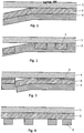
- Figure 1 the basic structure of a transfer film according to the invention is shown.
- a full-surface metallic layer 2 made of Cu is applied to a carrier film made of PET 1.
- a lacquer layer 3 is then applied to this full-area CU layer 2, which causes the Cu layer to detach from the carrier film during transfer to a substrate.
- FIG 2 shows a transfer film for the partial transfer of a Cu layer to a substrate.
- a partial Cu layer 2 is applied to the carrier film 1.
- the lacquer layer 3 is then applied over the entire surface.
- Figure 3 shows an alternative embodiment of a transfer film for the partial transfer of a Cu layer to a substrate.
- a partial adhesion promoter layer 5 is applied to the carrier film 1.
- a full-surface Cu layer 2 is then applied, and a full-surface lacquer layer 3 is applied to this Cu layer.
- the Cu layer separates from the carrier film 1 in those areas in which there is no adhesion promoter layer 5.
- both the Cu layer 2 and the lacquer layer 3 remain on the carrier film.
- Fig. 4 is an alternative embodiment to Fig. 3 shown, Here the lacquer layer is partially applied to the metallic layer. In the areas where the lacquer layer is present, the Cu layer separates from the carrier substrate during the transfer process
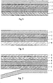
- FIG. 5 A transfer film according to the invention is shown, which is fixed on a substrate by means of an adhesive layer 7. After being fixed on the substrate, the carrier film 1 is pulled off, and the then exposed Cu layer can then be contacted
- FIG. 6 A multilayer structure of the transfer film according to the invention is shown.
- a further metallic layer 4 for example made of aluminum, is applied to the lacquer layer 3.
- the lacquer layer then lying between the two different metal layers also prevents an electrochemical interaction of the two metallic layers with one another.
- FIG. 7 a foil metallized on both sides is shown.
- a metallic layer 4 for example an Al layer, is initially placed on a further carrier film 6 upset.
- This carrier film 6 is then, for example by means of a lamination adhesive 8, against the lacquer layer 3 of a transfer film according to the invention, as shown in FIG Fig. 1 is shown, laminated.
- a film metallized on both sides is formed, in which the metallic layers are situated on opposite surfaces of the carrier film 6.
Landscapes
- Chemical & Material Sciences (AREA)
- Chemical Kinetics & Catalysis (AREA)
- Health & Medical Sciences (AREA)
- Organic Chemistry (AREA)
- Medicinal Chemistry (AREA)
- Polymers & Plastics (AREA)
- Engineering & Computer Science (AREA)
- Mechanical Engineering (AREA)
- Inorganic Chemistry (AREA)
- General Chemical & Material Sciences (AREA)
- General Health & Medical Sciences (AREA)
- Toxicology (AREA)
- Manufacturing & Machinery (AREA)
- Laminated Bodies (AREA)
- Decoration By Transfer Pictures (AREA)
Description
Die Erfindung betrifft eine Transferfolie gemäß dem Oberbegriff von Anspruch 1.The invention relates to a transfer film according to the preamble of
Transferfolien werden beispielsweise für den Transfer von Sicherheitselementen auf Wertdokumente, wie Banknoten, auf Sicherheitsdokumente wie Reisepässe oder Kreditkarten verwendet. Ferner finden Transferfolien bei der Herstellung elektronischer Bauelemente, insbesondere Leiterplatten, Anwendung.
Ein weiteres Anwendungsgebiet für Transferfolien ist der Einsatz bei der dekorativen Veredlung von Oberflächen.Transfer foils are used, for example, for the transfer of security elements to documents of value, such as banknotes, to security documents, such as passports or credit cards. Transfer films are also used in the production of electronic components, in particular printed circuit boards.
Another area of application for transfer foils is their use in the decorative finishing of surfaces.
Üblicherweise bestehen Transferfolien aus einer Trägerfolie, auf die die zu transferierenden Schichten aufgebracht sind. Die Übertragung der zu transferierenden Schichten auf das gewünschte Substrat erfolgt durch in-Kontakt-bringen der Schichten mit dem Substrat, wobei die transferierten Schichten auf dem Substrat mittels einer Kleberschicht fixiert werden. Anschließend wird die Trägerfolie der Transferfolie abgezogen.Transfer foils usually consist of a carrier foil to which the layers to be transferred are applied. The layers to be transferred are transferred to the desired substrate by bringing the layers into contact with the substrate, the transferred layers being fixed on the substrate by means of an adhesive layer. The carrier film of the transfer film is then removed.
Dazu müssen die zu transferierenden Schichten leicht und vollständig von dieser Trägerfolie ablösbar sein. Dazu wird auf der Trägerfolie üblicherweise vorerst eine sogenannte Releaseschicht vorgesehen, auf die dann die zu transferierenden Schichten aufgebracht werden. Die Releaseschicht ermöglicht die leichte Ablösbarkeit der Schichten von der Trägerfolie.For this purpose, the layers to be transferred must be easily and completely removable from this carrier film. For this purpose, a so-called release layer is usually initially provided on the carrier film, to which the layers to be transferred are then applied. The release layer enables the layers to be easily removed from the carrier film.
Eine Transferfolie der eingangsgenannten Art ist aus der
Aus
Nachteil dieser Releaseschicht ist, dass die Releaseschicht nach der Abtrennung der Trägerfolie auf den transferierten Schichten zurückbleibt. Das ist insbesondere bei der Verwendung von transferierten metallischen Schichten, insbesondere Kupferschichten zur Herstellung elektronischer Bauteile, wie Leiterplatten, von Nachteil, da die Kupferschicht dadurch nicht direkt kontaktierbar ist.The disadvantage of this release layer is that the release layer remains on the transferred layers after the carrier film has been separated. This is disadvantageous in particular when using transferred metallic layers, in particular copper layers for the production of electronic components, such as printed circuit boards, since the copper layer cannot be contacted directly as a result.
Zur Verminderung der Haftung von metallischen Schichten wurde daher versucht, die Oberfläche der Trägerfolie mechanisch oder chemisch (durch Behandlung mit Säuren) vorzubehandeln.To reduce the adhesion of metallic layers, attempts have therefore been made to pretreat the surface of the carrier film mechanically or chemically (by treatment with acids).
Durch die Behandlung der Folien wird die Oberflächenqualität verschlechtert. Durch die veränderte Oberfläche kommt es zu Störungen in der Beschichtungsqualität, welche sich negativ auf die Eigenschaften der zu transferierenden Schicht auswirkt.The treatment of the foils deteriorates the surface quality. The changed surface leads to disturbances in the coating quality, which has a negative effect on the properties of the layer to be transferred.
Aufgabe der Erfindung war es eine Transferfolie bereitzustellen, die die Nachteile des Standes der Technik beseitigt und bei der sich die zu transferierende metallische Schicht leicht von der Trägerfolie löst.The object of the invention was to provide a transfer film which eliminates the disadvantages of the prior art and in which the metallic layer to be transferred easily detaches from the carrier film.
Diese Aufgabe wird mit einer Transferfolie der eingangsgenannten Art durch die Merkmale des kennzeichnenden Teils von Anspruch 1 gelöst.This object is achieved with a transfer film of the type mentioned by the features of the characterizing part of
Als Trägerfolie kommen insbesondere flexible Kunststofffolien PI, PP, MOPP, PPS, PEEK, PEK, PEI, PSU, PAEK, LCP, PEN, PBT, PET, PA, PC, COC, POM, ABS, PVC, ETFE (Ethylentetrafluorethylen), PTFE (Polytetra-fluorethylen), PVF (Polyvinylfluorid), PVDF (Polyvinylidenfluorid), und EFEP (EthylenTetrafluorethylen-Hexafluorpropylen-Fluorterpolymer) in Frage.Flexible plastic films PI, PP, MOPP, PPS, PEEK, PEK, PEI, PSU, PAEK, LCP, PEN, PBT, PET, PA, PC, COC, POM, ABS, PVC, ETFE (ethylene tetrafluoroethylene), PTFE are used as carrier film (Polytetra-fluoroethylene), PVF (polyvinyl fluoride), PVDF (polyvinylidene fluoride), and EFEP (ethylene tetrafluoroethylene-hexafluoropropylene fluoropolymer).
Die Trägerfolien weisen vorzugsweise eine Dicke von 5 - 700 µm, bevorzugt 5 - 200 µm, besonders bevorzugt 23 - 50 µm auf.
Bevorzugt werden Trägerfolien aus PET (Polyethylentherephthalat) verwendet.The carrier films preferably have a thickness of 5 to 700 μm, preferably 5 to 200 μm, particularly preferably 23 to 50 μm.
Carrier films made of PET (polyethylene terephthalate) are preferably used.
Auf diese Trägerfolie wird eine metallische Schicht, durch PVD- oder CVD-Verfahren etwa durch thermisches Verdampfen, durch Sputtern oder Elektronenstrahlbedampfung abgeschieden.A metallic layer is deposited on this carrier film by PVD or CVD processes, for example by thermal evaporation, by sputtering or electron beam evaporation.
Als metallische Schichten eignen sich insbesondere Schichten aus Al, Cu, Ag, Au, Pt, Pd, Zn, Cr, Ti und dergleichen. Bevorzugt wird Cu verwendet.Layers made of Al, Cu, Ag, Au, Pt, Pd, Zn, Cr, Ti and the like are particularly suitable as metallic layers. Cu is preferably used.
In einem PVD- Verfahren wird die Beschichtung unter Vakuum (bis 10-12 mbar, vorzugsweise 10-2 bis 10-6 mbar) bei einer vom Dampfdruck und der Dicke der aufzubringenden Beschichtung abhängigen Temperatur auf dem Trägersubstrat beispielsweise durch thermisches Verdampfen, Lichtbogen- oder Elektronenstrahlverdampfen abgeschieden.In a PVD process, the coating is applied under vacuum (up to 10 -12 mbar, preferably 10 -2 to 10 -6 mbar) at a temperature dependent on the vapor pressure and the thickness of the coating to be applied to the carrier substrate, for example by thermal evaporation, arc or Electron beam evaporation deposited.
Eine weitere Möglichkeit ist das Aufbringen der Beschichtung durch AC- oder DC-Sputtern, wobei je nach Dicke der aufzubringenden Schicht und eingesetztem Material das entsprechende Verfahren gewählt wird.Another possibility is the application of the coating by AC or DC sputtering, the appropriate method being selected depending on the thickness of the layer to be applied and the material used.
In einem CVD-Verfahren werden die aufzubringenden Stoffe in Form von gasförmigen (z.B. organometallischen) Vorläuferverbindungen (sogenannten Precursoren) mittels eines inerten Trägergases (z.B. N2, Argon) in ein Vakuumbeschichtungssystem eingebracht, durch Eintrag von Energie aufgebrochen und zur Reaktion gebracht. Ein Teil der Reaktionsprodukte kondensiert auf dem Substrat und bildet dort die gewünschte Schicht, die übrigen Reaktionsprodukte werden über ein Vakuumsystem entfernt. Gasförmige Precursoren können z.B. CO, CO2, Sauerstoff, Silane, Methan, Ammoniak, Ferrocen, Trimethylaluminium, oder dergleichen sein.
Die Einbringung der Energie kann z.B. mittels eines lonen- oder Elektronenstrahls, eines Plasmas oder über erhöhte Temperatur erfolgen.In a CVD process, the substances to be applied are introduced into a vacuum coating system in the form of gaseous (e.g. organometallic) precursor compounds (so-called precursors) using an inert carrier gas (e.g. N 2 , argon), broken up by the input of energy and reacted. Some of the reaction products condense on the substrate and form the desired layer there, the remaining reaction products are removed using a vacuum system. Gaseous precursors can be, for example, CO, CO 2 , oxygen, silanes, methane, ammonia, ferrocene, trimethyl aluminum, or the like.
The energy can be introduced, for example, by means of an ion or electron beam, a plasma or via an elevated temperature.
Die metallische Schicht kann dabei vollflächig oder partiell auf das Trägersubstrat aufgebracht werden. Die Dicke der metallischen Schicht kann dabei 5 - 5000 nm, bevorzugt 25 - 1000 nm betragen.The metallic layer can be applied over the entire surface or partially on the carrier substrate. The thickness of the metallic layer can be 5 to 5000 nm, preferably 25 to 1000 nm.
Auf die metallische Schicht wird anschließend eine vollflächige oder partielle Schicht aus einem Lack aufgebracht.
Geeignet sind sowohl wässrige als auch lösungsmittelbasierte Lacksysteme auf Basis von Acrylaten oder deren Copymeren, auf Basis von Ethylenacrylatcopolymeren. Die Lackzusammensetzungen sind Lacke auf Basis von Ethylenacrylatcopolymeren, die als in Ammoniak stabilisierte Dispersion aufgebracht ist.A full or partial layer of lacquer is then applied to the metallic layer.
Both aqueous and solvent-based coating systems based on acrylates or their copymeres based on ethylene acrylate copolymers are suitable. The paint compositions are paints based on ethylene acrylate copolymers which are applied as a dispersion stabilized in ammonia.
Die Lackschicht kann durch ein Beschichtungsverfahren wie beispielsweise durch Aufstreichen, Gießen, Sprühen, Drucken (Siebdruck-, Tiefdruck-Flexodruck, oder Digitaldruckverfahren) oder Walzenauftragsverfahren auf die metallische Schicht aufgebracht werden.The lacquer layer can be applied to the metallic layer by a coating method such as, for example, by brushing, pouring, spraying, printing (screen printing, gravure flexo printing or digital printing method) or roller application method.
Die Lackschicht schwächt durch die metallische Schicht hindurch die Haftung der metallischen Schicht zur Trägerfolie. Das in der Lackschicht vorhandene Lösungsmittel unterwandert durch die jeder metallischen Schicht eigene Nano/Mikroporosität die metallische Schicht. Dieser Vorgang wird durch die Lackkomponenten der Lackschicht unterstützt. Dadurch wird die Haftung der metallischen Schicht an der Trägerfolie soweit geschwächt, dass die Aufbringung einer Releaseschicht auf das Trägersusbtrat bzw. die Vorbehandlung des Trägersubstrats nicht mehr notwendig istThe lacquer layer weakens the adhesion of the metallic layer to the carrier film through the metallic layer. The solvent present in the lacquer layer infiltrates the metallic layer due to the nano / microporosity inherent in each metallic layer. This process is supported by the paint components of the paint layer. As a result, the adhesion of the metallic layer to the carrier film is weakened to such an extent that the application of a release layer to the carrier substrate or the pretreatment of the carrier substrate is no longer necessary
Die metallische Schicht löst sich leicht und vollständig von der Trägerfolie und kann daher defektfrei und einfach auf ein Substrat transferiert werden. Dabei kann der Transfer einer metallischen Schicht vollflächig oder partiell erfolgen.The metallic layer is easily and completely detached from the carrier film and can therefore be transferred to a substrate easily and without defects. The transfer of a metallic layer can take place over the entire surface or partially.
Soll der Transfer der metallischen Schicht nur bereichsweise, das heißt partiell erfolgen, kann die metallische Schicht bereits partiell auf die Trägerfolie aufgebracht sein.If the transfer of the metallic layer is only to be carried out in regions, that is to say partially, the metallic layer can already be partially applied to the carrier film.
Alternativ ist es möglich auf der Trägerfolie eine partielle Haftvermittlerschicht vorzusehen und die metallische Schicht vollflächig auszuführen.
Beim Transfer auf ein Substrat wird dann die metallische Schicht nur in den Bereichen auf das Substrat übertragen, in denen keine Haftvermittlerschicht auf dem Trägersubstrat vorhanden ist, in den Bereichen der Haftvermittlerschicht verbleibt die metallische Schicht auf der Trägerfolie.Alternatively, it is possible to provide a partial adhesion promoter layer on the carrier film and to carry out the metal layer over the entire surface.
When transferring to a substrate, the metallic layer is then transferred to the substrate only in the areas in which there is no adhesion promoter layer on the carrier substrate; in the regions of the adhesion promoter layer, the metallic layer remains on the carrier film.
Alternativ ist es weiter möglich die Lackschicht nur partiell auf die metallische Schicht aufzubringen. In diesem Fall löst sich die metallische Schicht nur in jenen Bereichen vom Trägersubstrat, in denen auch die Lackschicht vorhanden ist.Alternatively, it is also possible to apply the lacquer layer only partially to the metallic layer. In this case, the metallic layer detaches from the carrier substrate only in those areas in which the lacquer layer is also present.
Es ist auch möglich mehrschichtige Aufbauten, gegebenenfalls mit gleichen oder unterschiedlichen metallischen Schichten, vollflächig oder partiell auf der Trägerfolie vorzusehen. Dabei werden die weitere metallische Schicht oder die weiteren metallischen Schichten nacheinander auf die auf der ersten metallischen Schicht vorhandene Lackschicht aufgebracht. Die Aufbringung dieser metallischen Schicht(en) erfolgt wie bereits beschrieben vorzugsweise durch ein PVD- oder CVD-Verfahren.It is also possible to provide multilayer structures, possibly with the same or different metallic layers, over the entire surface or partially on the carrier film. The further metallic layer or the further metallic layers are successively applied to the lacquer layer on the first metallic layer. As already described, this metallic layer (s) is preferably applied by a PVD or CVD process.
Auch weitere vollflächige oder partielle Lackschichten können in Kombination mit Metallen oder Metalloxiden nacheinander aufgebracht werden, z.B. zur Herstellung von Halbleitern.Other full or partial layers of lacquer can also be applied in combination with metals or metal oxides, e.g. for the production of semiconductors.
Die weiteren Lackschichten können auch polymere Lackschichten sein, die beispielsweise optische, optisch aktive oder magnetische Merkmale aufweisen können.The further lacquer layers can also be polymeric lacquer layers, which can have optical, optically active or magnetic features, for example.
Unter optischen Merkmalen werden hier insbesondere einen Farbeindruck hervorrufende Merkmale verstanden. Optisch aktive Merkmale werden beispielsweise von diffraktiven Strukturen, wie Hologrammen, Beugungsstrukturen, Oberflächenreliefs und dergleichen hervorgerufen.Optical features are understood here to mean, in particular, features that produce a color impression. Optically active features are caused, for example, by diffractive structures, such as holograms, diffraction structures, surface reliefs and the like.
Diese Lackschichten können vollflächig oder partiell, beispielsweise in Form von Zeichen, Mustern, Buchstaben Symbolen oder in Form einer Codierung aufgebracht sein.These lacquer layers can be applied over the entire surface or partially, for example in the form of characters, patterns, letters, symbols or in the form of a coding.
Der Schichtaufbau kann anschließend mit einer Kleberschicht versehen werden, durch die die zu transferierenden Schichten auf einem Substrat fixiert werden. Alternativ kann diese Kleberschicht auch auf dem Substrat vorhanden sein. Die Kleberschicht kann dabei vollflächig oder partiell aufgebracht sein.The layer structure can then be provided with an adhesive layer, by means of which the layers to be transferred are fixed on a substrate. Alternatively, this adhesive layer can also be present on the substrate. The adhesive layer can be applied over the entire surface or partially.
Als Klebebeschichtungen kommen beispielsweise Selbstklebebeschichtungen Heiß- oder Kaltsiegelklebebeschichtungen, 1 oder 2-Komponenten-Klebersysteme, Selbstklebefolien oder Hotmeltfolien in Frage.Self-adhesive coatings, for example hot-melt or cold-seal adhesive coatings, 1 or 2-component adhesive systems, self-adhesive films or hot-melt films are suitable as adhesive coatings.
Besonders geeignet ist die Transferfolie zum Transfer von metallischen Schichten auf Substrate, die nicht direkt mit einer metallischen Schicht versehen werden können, beispielsweise Gewebe, Polyethylenfolien, die nicht ausreichend temperaturbeständig sind oder Materialien, die stark ausgasen, wie beispielsweise Papier oder Papierverbunde, geschäumte Folien und dergleichen.The transfer film is particularly suitable for the transfer of metallic layers to substrates that cannot be directly provided with a metallic layer, for example fabrics, polyethylene films that are not sufficiently temperature-resistant or materials that strongly emit gases, such as paper or paper composites, foamed films and the like.
Daher sind mit dieser Transferfolie auch beispielsweise Sicherheitselemente für Wertdokumente, wie Banknoten Sicherheitspapiere, Ausweise und dergleichen herstellbar. Die Sicherheitselemente können dabei in Form von Fäden, Streifen oder Patches vorliegen.For this reason, security elements for documents of value, such as banknotes, security papers, ID cards and the like can also be produced with this transfer film. The security elements can be in the form of threads, strips or patches.
Ferner ist die erfindungsgemäße Transferfolie geeignet zur Herstellung elektronischer Bauteile, da eine metallische Cu-Schicht nach dem Transfer einwandfrei kontaktierbar ist.Furthermore, the transfer film according to the invention is suitable for the production of electronic components, since a metallic Cu layer can be contacted perfectly after the transfer.
Die erfindungsgemäße Transferfolie ist auch geeignet zum Transfer auf Oberflächen von Plattenware oder Stückgut, insbesondere auch auf dreidimensionale Oberflächen, bzw. zum Transfer auf Oberflächen die anschließend dreidimensional verformt werden sollen.The transfer film according to the invention is also suitable for transfer to surfaces of sheet or piece goods, in particular also to three-dimensional surfaces, or for transfer to surfaces which are subsequently to be deformed three-dimensionally.
In den
Darin bedeuten
- 1 die Trägerfolie
- 2 die metallische Schicht, wie eine Cu-Schicht
- 3 die Lackschicht
- 4 eine weitere metallische Schicht, beispielsweise eine Al-Schicht
- 5 eine Haftvermittlerschicht
- 6 eine weitere Trägerfolie
- 7 eine Klebebeschichtung zur Fixierung auf einem Substrat
- 8 eine Kaschierkleberschicht
- 1 the carrier film
- 2 the metallic layer, like a Cu layer
- 3 the paint layer
- 4 a further metallic layer, for example an Al layer
- 5 an adhesion promoter layer
- 6 another carrier film
- 7 an adhesive coating for fixing on a substrate
- 8 a laminating adhesive layer
In
Auf diese vollflächige CU-Schicht 2 ist anschließend eine Lackschicht 3 aufgebracht, die die Ablösung der Cu-Schicht von der Trägerfolie beim Transfer auf ein Substrat bewirkt.In
A
In
In
In
Auf die Trägerfolie 1 ist eine partielle Haftvermittlerschicht 5 aufgebracht. Anschließend wird eine vollflächige Cu-Schicht 2 und auf diese Cu-Schicht eine vollflächige Lackschicht 3 aufgebracht.
Beim Transfer trennt sich beim Abtrennen der Trägerfolie die Cu-Schicht in jenen Bereichen von der Trägerfolie 1, in denen keine Haftvermittlerschicht 5 vorhanden ist. In den Bereichen, in denen die Haftvermittlerschicht auf der Trägerfolie vorhanden ist, verbleibt sowohl die Cu-Schicht 2 als auch die Lackschicht 3 auf der Trägerfolie.A partial
During the transfer, when the carrier film is separated, the Cu layer separates from the
In
In
In
Auf den wie in
Es ist aber auch möglich, anstelle der Al- Schicht eine weitere Cu-Schicht auf die Lackschicht aufzubringen.In
On the as in
However, it is also possible to apply a further Cu layer to the lacquer layer instead of the Al layer.
In
Claims (11)
- A transfer film comprising a carrier film and a metallic layer applied thereto, wherein a layer of a lacquer is applied to the metallic layer, wherein the lacquer layer consists of a water-containing or solvent-containing lacquer system based on acrylates or copolymers thereof, characterized in that the lacquer layer based on ethylene-acrylate copolymers is applied as a dispersion stabilized with ammonia and reduces the adhesion of the metallic layer to the carrier film through the metallic layer.
- The transfer film according to claim 1, characterized in that the metallic layer consists of Al, Cu, Ag, Au, Pt, Pd, Zn, Cr, Ti.
- The transfer film according to one of claims 1 or 2, characterized in that the metallic layer is applied to the carrier film on the full surface or partially.
- The transfer film according to one of claims 1 to 3, characterized in that the lacquer layer is applied to the metallic layer on the full surface or partially.
- The transfer film according to one of claims 1 to 4, characterized in that a bonding layer is partially applied to the carrier film.
- The transfer film according to one of claims 1 to 5, characterized in that a further metallic layer is applied to the lacquer layer.
- The transfer film according to one of claims 1 to 6, characterized in that a full-surface or partial printing layer with optical optically active or magnetic features is applied to the lacquer layer.
- The transfer film according to one of claims 1 to 7, characterized in that the transfer film is provided with an adhesive layer situated on the layer structure.
- The transfer film according to one of claims 1 to 8, characterized in that the transfer film is laminated on the side of the lacquer layer against a further carrier film which has a further metallic layer on the opposite surface.
- A method for producing a transfer film, characterized by the following method steps:- providing a carrier film- applying a metallic layer to a surface of the carrier film- applying a lacquer layer which is based on ethylene-acrylate copolymers and stabilized with ammonia to the metallic layer.
- Use of the transfer film according to one of claims 1 to 9 for producing security elements for value documents and security papers, electronic components such as circuit boards, for applying metallic layers to surfaces of pallet goods or piece goods.
Priority Applications (2)
| Application Number | Priority Date | Filing Date | Title |
|---|---|---|---|
| EP16000472.7A EP3211027B1 (en) | 2016-02-26 | 2016-02-26 | Transfer film with metallic layer and method for its production |
| PCT/EP2016/002192 WO2017144074A1 (en) | 2016-02-26 | 2016-12-27 | Transfer film with a metallic layer, and method for producing same |
Applications Claiming Priority (1)
| Application Number | Priority Date | Filing Date | Title |
|---|---|---|---|
| EP16000472.7A EP3211027B1 (en) | 2016-02-26 | 2016-02-26 | Transfer film with metallic layer and method for its production |
Publications (2)
| Publication Number | Publication Date |
|---|---|
| EP3211027A1 EP3211027A1 (en) | 2017-08-30 |
| EP3211027B1 true EP3211027B1 (en) | 2020-07-01 |
Family
ID=55524042
Family Applications (1)
| Application Number | Title | Priority Date | Filing Date |
|---|---|---|---|
| EP16000472.7A Active EP3211027B1 (en) | 2016-02-26 | 2016-02-26 | Transfer film with metallic layer and method for its production |
Country Status (2)
| Country | Link |
|---|---|
| EP (1) | EP3211027B1 (en) |
| WO (1) | WO2017144074A1 (en) |
Family Cites Families (6)
| Publication number | Priority date | Publication date | Assignee | Title |
|---|---|---|---|---|
| DE3743040A1 (en) * | 1987-12-18 | 1989-07-13 | Basf Ag | METHOD FOR PRODUCING AQUEOUS POLYMER DISPERSIONS |
| US5128207A (en) * | 1989-03-08 | 1992-07-07 | Siemens Aktiengesellschaft | Method for producing uniform polymethylmethacrylate layers |
| JPH05155160A (en) * | 1991-12-03 | 1993-06-22 | Brother Ind Ltd | Ink ribbon for producing dry transfer material |
| WO2007048563A2 (en) | 2005-10-27 | 2007-05-03 | Ovd Kinegram Ag | Method for transferring a multilayer body and a transfer film |
| EP1785268A1 (en) * | 2005-11-12 | 2007-05-16 | Hueck Folien Ges.m.b.H | Decorative sheet |
| EP1818425A1 (en) * | 2006-02-06 | 2007-08-15 | Hueck Folien Ges.m.b.H. | Method for making partially metallized substrates |
-
2016
- 2016-02-26 EP EP16000472.7A patent/EP3211027B1/en active Active
- 2016-12-27 WO PCT/EP2016/002192 patent/WO2017144074A1/en active Application Filing
Non-Patent Citations (1)
| Title |
|---|
| None * |
Also Published As
| Publication number | Publication date |
|---|---|
| WO2017144074A1 (en) | 2017-08-31 |
| EP3211027A1 (en) | 2017-08-30 |
Similar Documents
| Publication | Publication Date | Title |
|---|---|---|
| EP2578414B1 (en) | Security element with colour-switching effect, use of same and method for producing same | |
| EP1291463A1 (en) | Process for producing a selectively metallized foil, and their products | |
| EP2851194B1 (en) | Safety element, in particular safety label | |
| AT501356A1 (en) | SAFETY ELEMENTS AND SAFETY FEATURES WITH COLOR EFFECTS | |
| WO2016202416A1 (en) | Security label with evidence of tampering | |
| AT502319B1 (en) | SUBSTRATES WITH PREFERABLY TRANSFERABLE LAYERS AND / OR SURFACE STRUCTURES, METHOD FOR THEIR PRODUCTION AND THEIR USE | |
| EP1871616B1 (en) | Security element having a spatially resolved magnetic coding, method and device for producing the same and the use thereof | |
| EP1584647B2 (en) | Sheet material with optical features | |
| EP3211027B1 (en) | Transfer film with metallic layer and method for its production | |
| AT520010B1 (en) | Process for the selective coating of surface areas of a lacquer layer | |
| WO2016055166A2 (en) | Coating film, layered structure and method for coating a substrate | |
| AT523393B1 (en) | Process for the production of a security element with a colored microstructure | |
| AT520011B1 (en) | Method for producing a security element and security element produced by this method and its use | |
| WO2008009447A2 (en) | Multilayered body comprising an electroconductive polymer layer and method for the production thereof | |
| WO2020002010A1 (en) | Method and device for print enhancement | |
| EP2251207B1 (en) | Method for the manufacture of a safety marker | |
| AT504631B1 (en) | FOIL MATERIALS, ESPECIALLY FOR SAFETY ELEMENTS | |
| EP2711191B1 (en) | Method for printing films | |
| EP2450196B1 (en) | Method for manufacturing safety paper | |
| AT507353B1 (en) | METHOD OF STRUCTURING INORGANIC OR ORGANIC LAYERS | |
| AT503712A2 (en) | CODED OPTICALLY ACTIVE SECURITY ELEMENTS AND SAFETY FEATURES | |
| DE102015226246A1 (en) | Process for producing a surface for the transport of printing material |
Legal Events
| Date | Code | Title | Description |
|---|---|---|---|
| PUAI | Public reference made under article 153(3) epc to a published international application that has entered the european phase |
Free format text: ORIGINAL CODE: 0009012 |
|
| STAA | Information on the status of an ep patent application or granted ep patent |
Free format text: STATUS: THE APPLICATION HAS BEEN PUBLISHED |
|
| AK | Designated contracting states |
Kind code of ref document: A1 Designated state(s): AL AT BE BG CH CY CZ DE DK EE ES FI FR GB GR HR HU IE IS IT LI LT LU LV MC MK MT NL NO PL PT RO RS SE SI SK SM TR |
|
| AX | Request for extension of the european patent |
Extension state: BA ME |
|
| STAA | Information on the status of an ep patent application or granted ep patent |
Free format text: STATUS: REQUEST FOR EXAMINATION WAS MADE |
|
| 17P | Request for examination filed |
Effective date: 20180222 |
|
| RBV | Designated contracting states (corrected) |
Designated state(s): AL AT BE BG CH CY CZ DE DK EE ES FI FR GB GR HR HU IE IS IT LI LT LU LV MC MK MT NL NO PL PT RO RS SE SI SK SM TR |
|
| STAA | Information on the status of an ep patent application or granted ep patent |
Free format text: STATUS: EXAMINATION IS IN PROGRESS |
|
| 17Q | First examination report despatched |
Effective date: 20180704 |
|
| RAP1 | Party data changed (applicant data changed or rights of an application transferred) |
Owner name: HUECK FOLIEN GESELLSCHAFT M.B.H. |
|
| GRAP | Despatch of communication of intention to grant a patent |
Free format text: ORIGINAL CODE: EPIDOSNIGR1 |
|
| STAA | Information on the status of an ep patent application or granted ep patent |
Free format text: STATUS: GRANT OF PATENT IS INTENDED |
|
| INTG | Intention to grant announced |
Effective date: 20200214 |
|
| GRAS | Grant fee paid |
Free format text: ORIGINAL CODE: EPIDOSNIGR3 |
|
| GRAA | (expected) grant |
Free format text: ORIGINAL CODE: 0009210 |
|
| STAA | Information on the status of an ep patent application or granted ep patent |
Free format text: STATUS: THE PATENT HAS BEEN GRANTED |
|
| AK | Designated contracting states |
Kind code of ref document: B1 Designated state(s): AL AT BE BG CH CY CZ DE DK EE ES FI FR GB GR HR HU IE IS IT LI LT LU LV MC MK MT NL NO PL PT RO RS SE SI SK SM TR |
|
| REG | Reference to a national code |
Ref country code: AT Ref legal event code: REF Ref document number: 1286149 Country of ref document: AT Kind code of ref document: T Effective date: 20200715 Ref country code: CH Ref legal event code: EP |
|
| REG | Reference to a national code |
Ref country code: IE Ref legal event code: FG4D Free format text: LANGUAGE OF EP DOCUMENT: GERMAN |
|
| REG | Reference to a national code |
Ref country code: DE Ref legal event code: R096 Ref document number: 502016010353 Country of ref document: DE |
|
| REG | Reference to a national code |
Ref country code: LT Ref legal event code: MG4D |
|
| PG25 | Lapsed in a contracting state [announced via postgrant information from national office to epo] |
Ref country code: BG Free format text: LAPSE BECAUSE OF FAILURE TO SUBMIT A TRANSLATION OF THE DESCRIPTION OR TO PAY THE FEE WITHIN THE PRESCRIBED TIME-LIMIT Effective date: 20201001 |
|
| REG | Reference to a national code |
Ref country code: NL Ref legal event code: MP Effective date: 20200701 |
|
| PG25 | Lapsed in a contracting state [announced via postgrant information from national office to epo] |
Ref country code: NO Free format text: LAPSE BECAUSE OF FAILURE TO SUBMIT A TRANSLATION OF THE DESCRIPTION OR TO PAY THE FEE WITHIN THE PRESCRIBED TIME-LIMIT Effective date: 20201001 Ref country code: FI Free format text: LAPSE BECAUSE OF FAILURE TO SUBMIT A TRANSLATION OF THE DESCRIPTION OR TO PAY THE FEE WITHIN THE PRESCRIBED TIME-LIMIT Effective date: 20200701 Ref country code: LT Free format text: LAPSE BECAUSE OF FAILURE TO SUBMIT A TRANSLATION OF THE DESCRIPTION OR TO PAY THE FEE WITHIN THE PRESCRIBED TIME-LIMIT Effective date: 20200701 Ref country code: HR Free format text: LAPSE BECAUSE OF FAILURE TO SUBMIT A TRANSLATION OF THE DESCRIPTION OR TO PAY THE FEE WITHIN THE PRESCRIBED TIME-LIMIT Effective date: 20200701 Ref country code: CZ Free format text: LAPSE BECAUSE OF FAILURE TO SUBMIT A TRANSLATION OF THE DESCRIPTION OR TO PAY THE FEE WITHIN THE PRESCRIBED TIME-LIMIT Effective date: 20200701 Ref country code: PT Free format text: LAPSE BECAUSE OF FAILURE TO SUBMIT A TRANSLATION OF THE DESCRIPTION OR TO PAY THE FEE WITHIN THE PRESCRIBED TIME-LIMIT Effective date: 20201102 Ref country code: SE Free format text: LAPSE BECAUSE OF FAILURE TO SUBMIT A TRANSLATION OF THE DESCRIPTION OR TO PAY THE FEE WITHIN THE PRESCRIBED TIME-LIMIT Effective date: 20200701 Ref country code: GR Free format text: LAPSE BECAUSE OF FAILURE TO SUBMIT A TRANSLATION OF THE DESCRIPTION OR TO PAY THE FEE WITHIN THE PRESCRIBED TIME-LIMIT Effective date: 20201002 Ref country code: ES Free format text: LAPSE BECAUSE OF FAILURE TO SUBMIT A TRANSLATION OF THE DESCRIPTION OR TO PAY THE FEE WITHIN THE PRESCRIBED TIME-LIMIT Effective date: 20200701 |
|
| PG25 | Lapsed in a contracting state [announced via postgrant information from national office to epo] |
Ref country code: IS Free format text: LAPSE BECAUSE OF FAILURE TO SUBMIT A TRANSLATION OF THE DESCRIPTION OR TO PAY THE FEE WITHIN THE PRESCRIBED TIME-LIMIT Effective date: 20201101 Ref country code: PL Free format text: LAPSE BECAUSE OF FAILURE TO SUBMIT A TRANSLATION OF THE DESCRIPTION OR TO PAY THE FEE WITHIN THE PRESCRIBED TIME-LIMIT Effective date: 20200701 Ref country code: LV Free format text: LAPSE BECAUSE OF FAILURE TO SUBMIT A TRANSLATION OF THE DESCRIPTION OR TO PAY THE FEE WITHIN THE PRESCRIBED TIME-LIMIT Effective date: 20200701 Ref country code: RS Free format text: LAPSE BECAUSE OF FAILURE TO SUBMIT A TRANSLATION OF THE DESCRIPTION OR TO PAY THE FEE WITHIN THE PRESCRIBED TIME-LIMIT Effective date: 20200701 |
|
| PG25 | Lapsed in a contracting state [announced via postgrant information from national office to epo] |
Ref country code: NL Free format text: LAPSE BECAUSE OF FAILURE TO SUBMIT A TRANSLATION OF THE DESCRIPTION OR TO PAY THE FEE WITHIN THE PRESCRIBED TIME-LIMIT Effective date: 20200701 |
|
| REG | Reference to a national code |
Ref country code: DE Ref legal event code: R097 Ref document number: 502016010353 Country of ref document: DE |
|
| PG25 | Lapsed in a contracting state [announced via postgrant information from national office to epo] |
Ref country code: RO Free format text: LAPSE BECAUSE OF FAILURE TO SUBMIT A TRANSLATION OF THE DESCRIPTION OR TO PAY THE FEE WITHIN THE PRESCRIBED TIME-LIMIT Effective date: 20200701 Ref country code: SM Free format text: LAPSE BECAUSE OF FAILURE TO SUBMIT A TRANSLATION OF THE DESCRIPTION OR TO PAY THE FEE WITHIN THE PRESCRIBED TIME-LIMIT Effective date: 20200701 Ref country code: EE Free format text: LAPSE BECAUSE OF FAILURE TO SUBMIT A TRANSLATION OF THE DESCRIPTION OR TO PAY THE FEE WITHIN THE PRESCRIBED TIME-LIMIT Effective date: 20200701 Ref country code: DK Free format text: LAPSE BECAUSE OF FAILURE TO SUBMIT A TRANSLATION OF THE DESCRIPTION OR TO PAY THE FEE WITHIN THE PRESCRIBED TIME-LIMIT Effective date: 20200701 Ref country code: IT Free format text: LAPSE BECAUSE OF FAILURE TO SUBMIT A TRANSLATION OF THE DESCRIPTION OR TO PAY THE FEE WITHIN THE PRESCRIBED TIME-LIMIT Effective date: 20200701 |
|
| PLBE | No opposition filed within time limit |
Free format text: ORIGINAL CODE: 0009261 |
|
| STAA | Information on the status of an ep patent application or granted ep patent |
Free format text: STATUS: NO OPPOSITION FILED WITHIN TIME LIMIT |
|
| PG25 | Lapsed in a contracting state [announced via postgrant information from national office to epo] |
Ref country code: AL Free format text: LAPSE BECAUSE OF FAILURE TO SUBMIT A TRANSLATION OF THE DESCRIPTION OR TO PAY THE FEE WITHIN THE PRESCRIBED TIME-LIMIT Effective date: 20200701 |
|
| 26N | No opposition filed |
Effective date: 20210406 |
|
| PG25 | Lapsed in a contracting state [announced via postgrant information from national office to epo] |
Ref country code: SK Free format text: LAPSE BECAUSE OF FAILURE TO SUBMIT A TRANSLATION OF THE DESCRIPTION OR TO PAY THE FEE WITHIN THE PRESCRIBED TIME-LIMIT Effective date: 20200701 |
|
| PG25 | Lapsed in a contracting state [announced via postgrant information from national office to epo] |
Ref country code: SI Free format text: LAPSE BECAUSE OF FAILURE TO SUBMIT A TRANSLATION OF THE DESCRIPTION OR TO PAY THE FEE WITHIN THE PRESCRIBED TIME-LIMIT Effective date: 20200701 |
|
| REG | Reference to a national code |
Ref country code: DE Ref legal event code: R119 Ref document number: 502016010353 Country of ref document: DE |
|
| PG25 | Lapsed in a contracting state [announced via postgrant information from national office to epo] |
Ref country code: MC Free format text: LAPSE BECAUSE OF FAILURE TO SUBMIT A TRANSLATION OF THE DESCRIPTION OR TO PAY THE FEE WITHIN THE PRESCRIBED TIME-LIMIT Effective date: 20200701 |
|
| GBPC | Gb: european patent ceased through non-payment of renewal fee |
Effective date: 20210226 |
|
| REG | Reference to a national code |
Ref country code: BE Ref legal event code: MM Effective date: 20210228 |
|
| PG25 | Lapsed in a contracting state [announced via postgrant information from national office to epo] |
Ref country code: CH Free format text: LAPSE BECAUSE OF NON-PAYMENT OF DUE FEES Effective date: 20210228 Ref country code: LI Free format text: LAPSE BECAUSE OF NON-PAYMENT OF DUE FEES Effective date: 20210228 Ref country code: LU Free format text: LAPSE BECAUSE OF NON-PAYMENT OF DUE FEES Effective date: 20210226 |
|
| PG25 | Lapsed in a contracting state [announced via postgrant information from national office to epo] |
Ref country code: IE Free format text: LAPSE BECAUSE OF NON-PAYMENT OF DUE FEES Effective date: 20210226 Ref country code: GB Free format text: LAPSE BECAUSE OF NON-PAYMENT OF DUE FEES Effective date: 20210226 Ref country code: FR Free format text: LAPSE BECAUSE OF NON-PAYMENT OF DUE FEES Effective date: 20210228 Ref country code: DE Free format text: LAPSE BECAUSE OF NON-PAYMENT OF DUE FEES Effective date: 20210901 |
|
| PG25 | Lapsed in a contracting state [announced via postgrant information from national office to epo] |
Ref country code: BE Free format text: LAPSE BECAUSE OF NON-PAYMENT OF DUE FEES Effective date: 20210228 |
|
| PG25 | Lapsed in a contracting state [announced via postgrant information from national office to epo] |
Ref country code: HU Free format text: LAPSE BECAUSE OF FAILURE TO SUBMIT A TRANSLATION OF THE DESCRIPTION OR TO PAY THE FEE WITHIN THE PRESCRIBED TIME-LIMIT; INVALID AB INITIO Effective date: 20160226 |
|
| PG25 | Lapsed in a contracting state [announced via postgrant information from national office to epo] |
Ref country code: CY Free format text: LAPSE BECAUSE OF FAILURE TO SUBMIT A TRANSLATION OF THE DESCRIPTION OR TO PAY THE FEE WITHIN THE PRESCRIBED TIME-LIMIT Effective date: 20200701 |
|
| PGFP | Annual fee paid to national office [announced via postgrant information from national office to epo] |
Ref country code: AT Payment date: 20240202 Year of fee payment: 9 |
|
| PG25 | Lapsed in a contracting state [announced via postgrant information from national office to epo] |
Ref country code: MK Free format text: LAPSE BECAUSE OF FAILURE TO SUBMIT A TRANSLATION OF THE DESCRIPTION OR TO PAY THE FEE WITHIN THE PRESCRIBED TIME-LIMIT Effective date: 20200701 |