EP3210819A1 - Support assembly for a vehicle comprising a spherical tire - Google Patents
Support assembly for a vehicle comprising a spherical tire Download PDFInfo
- Publication number
- EP3210819A1 EP3210819A1 EP17156477.6A EP17156477A EP3210819A1 EP 3210819 A1 EP3210819 A1 EP 3210819A1 EP 17156477 A EP17156477 A EP 17156477A EP 3210819 A1 EP3210819 A1 EP 3210819A1
- Authority
- EP
- European Patent Office
- Prior art keywords
- support assembly
- tires
- spherical
- drive system
- vehicle
- Prior art date
- Legal status (The legal status is an assumption and is not a legal conclusion. Google has not performed a legal analysis and makes no representation as to the accuracy of the status listed.)
- Withdrawn
Links
- 239000000463 material Substances 0.000 claims abstract description 25
- 229920001971 elastomer Polymers 0.000 claims description 91
- 229920000642 polymer Polymers 0.000 claims description 78
- 239000005060 rubber Substances 0.000 claims description 64
- 230000005291 magnetic effect Effects 0.000 claims description 62
- -1 poly(N-isopropylacrylamide) Polymers 0.000 claims description 38
- 229920003048 styrene butadiene rubber Polymers 0.000 claims description 30
- 239000000806 elastomer Substances 0.000 claims description 27
- 229920003213 poly(N-isopropyl acrylamide) Polymers 0.000 claims description 16
- 239000005062 Polybutadiene Substances 0.000 claims description 15
- 150000001993 dienes Chemical class 0.000 claims description 14
- 229920002857 polybutadiene Polymers 0.000 claims description 11
- 229920003051 synthetic elastomer Polymers 0.000 claims description 7
- 239000000839 emulsion Substances 0.000 claims description 5
- 229920001194 natural rubber Polymers 0.000 claims description 4
- 238000013016 damping Methods 0.000 claims description 2
- 229920001977 poly(N,N-diethylacrylamides) Polymers 0.000 claims description 2
- 230000008093 supporting effect Effects 0.000 claims description 2
- PPBRXRYQALVLMV-UHFFFAOYSA-N Styrene Chemical compound C=CC1=CC=CC=C1 PPBRXRYQALVLMV-UHFFFAOYSA-N 0.000 description 36
- 230000007246 mechanism Effects 0.000 description 34
- KAKZBPTYRLMSJV-UHFFFAOYSA-N Butadiene Chemical compound C=CC=C KAKZBPTYRLMSJV-UHFFFAOYSA-N 0.000 description 30
- 230000033001 locomotion Effects 0.000 description 27
- 230000006854 communication Effects 0.000 description 21
- 238000004891 communication Methods 0.000 description 21
- 239000000203 mixture Substances 0.000 description 21
- 239000000178 monomer Substances 0.000 description 20
- 150000001875 compounds Chemical class 0.000 description 19
- 229920001577 copolymer Polymers 0.000 description 19
- 239000002174 Styrene-butadiene Substances 0.000 description 18
- 238000000034 method Methods 0.000 description 17
- VYPSYNLAJGMNEJ-UHFFFAOYSA-N Silicium dioxide Chemical compound O=[Si]=O VYPSYNLAJGMNEJ-UHFFFAOYSA-N 0.000 description 16
- NINIDFKCEFEMDL-UHFFFAOYSA-N Sulfur Chemical group [S] NINIDFKCEFEMDL-UHFFFAOYSA-N 0.000 description 15
- 229910052717 sulfur Inorganic materials 0.000 description 14
- 239000011593 sulfur Substances 0.000 description 14
- 238000012545 processing Methods 0.000 description 13
- 239000003921 oil Substances 0.000 description 12
- 235000019198 oils Nutrition 0.000 description 12
- 239000011557 critical solution Substances 0.000 description 11
- NLHHRLWOUZZQLW-UHFFFAOYSA-N Acrylonitrile Chemical compound C=CC#N NLHHRLWOUZZQLW-UHFFFAOYSA-N 0.000 description 10
- RRHGJUQNOFWUDK-UHFFFAOYSA-N Isoprene Chemical compound CC(=C)C=C RRHGJUQNOFWUDK-UHFFFAOYSA-N 0.000 description 10
- 238000003860 storage Methods 0.000 description 10
- 230000001747 exhibiting effect Effects 0.000 description 9
- 230000006870 function Effects 0.000 description 9
- 239000002184 metal Substances 0.000 description 9
- 125000004432 carbon atom Chemical group C* 0.000 description 8
- 239000012986 chain transfer agent Substances 0.000 description 8
- 239000003795 chemical substances by application Substances 0.000 description 8
- 238000010168 coupling process Methods 0.000 description 8
- 238000005859 coupling reaction Methods 0.000 description 8
- 238000007720 emulsion polymerization reaction Methods 0.000 description 8
- 238000005339 levitation Methods 0.000 description 8
- 229910052751 metal Inorganic materials 0.000 description 8
- 229920001897 terpolymer Polymers 0.000 description 8
- MTAZNLWOLGHBHU-UHFFFAOYSA-N butadiene-styrene rubber Chemical compound C=CC=C.C=CC1=CC=CC=C1 MTAZNLWOLGHBHU-UHFFFAOYSA-N 0.000 description 7
- 239000003086 colorant Substances 0.000 description 7
- 230000008878 coupling Effects 0.000 description 7
- 239000000945 filler Substances 0.000 description 7
- 125000000524 functional group Chemical group 0.000 description 7
- 229920000578 graft copolymer Polymers 0.000 description 7
- 230000003993 interaction Effects 0.000 description 7
- 150000003961 organosilicon compounds Chemical class 0.000 description 7
- 239000000377 silicon dioxide Substances 0.000 description 7
- 238000012546 transfer Methods 0.000 description 7
- 125000000391 vinyl group Chemical group [H]C([*])=C([H])[H] 0.000 description 7
- 238000000576 coating method Methods 0.000 description 6
- DOIRQSBPFJWKBE-UHFFFAOYSA-N dibutyl phthalate Chemical compound CCCCOC(=O)C1=CC=CC=C1C(=O)OCCCC DOIRQSBPFJWKBE-UHFFFAOYSA-N 0.000 description 6
- HQQADJVZYDDRJT-UHFFFAOYSA-N ethene;prop-1-ene Chemical group C=C.CC=C HQQADJVZYDDRJT-UHFFFAOYSA-N 0.000 description 6
- 239000001257 hydrogen Substances 0.000 description 6
- 229910052739 hydrogen Inorganic materials 0.000 description 6
- 229920001195 polyisoprene Polymers 0.000 description 6
- 238000004073 vulcanization Methods 0.000 description 6
- XLYOFNOQVPJJNP-UHFFFAOYSA-N water Substances O XLYOFNOQVPJJNP-UHFFFAOYSA-N 0.000 description 6
- 230000009471 action Effects 0.000 description 5
- 125000000217 alkyl group Chemical group 0.000 description 5
- 239000006229 carbon black Substances 0.000 description 5
- 235000019241 carbon black Nutrition 0.000 description 5
- 238000006243 chemical reaction Methods 0.000 description 5
- 229920003193 cis-1,4-polybutadiene polymer Polymers 0.000 description 5
- 238000010528 free radical solution polymerization reaction Methods 0.000 description 5
- 150000002430 hydrocarbons Chemical class 0.000 description 5
- 238000002156 mixing Methods 0.000 description 5
- 238000006116 polymerization reaction Methods 0.000 description 5
- 239000000243 solution Substances 0.000 description 5
- 239000005061 synthetic rubber Substances 0.000 description 5
- 125000003396 thiol group Chemical group [H]S* 0.000 description 5
- 229920002554 vinyl polymer Polymers 0.000 description 5
- ZGHFDIIVVIFNPS-UHFFFAOYSA-N 3-Methyl-3-buten-2-one Chemical compound CC(=C)C(C)=O ZGHFDIIVVIFNPS-UHFFFAOYSA-N 0.000 description 4
- HGINCPLSRVDWNT-UHFFFAOYSA-N Acrolein Chemical compound C=CC=O HGINCPLSRVDWNT-UHFFFAOYSA-N 0.000 description 4
- 239000004215 Carbon black (E152) Substances 0.000 description 4
- XLOMVQKBTHCTTD-UHFFFAOYSA-N Zinc monoxide Chemical compound [Zn]=O XLOMVQKBTHCTTD-UHFFFAOYSA-N 0.000 description 4
- 239000000654 additive Substances 0.000 description 4
- 229920005549 butyl rubber Polymers 0.000 description 4
- 239000011203 carbon fibre reinforced carbon Substances 0.000 description 4
- 238000004146 energy storage Methods 0.000 description 4
- FJKIXWOMBXYWOQ-UHFFFAOYSA-N ethenoxyethane Chemical compound CCOC=C FJKIXWOMBXYWOQ-UHFFFAOYSA-N 0.000 description 4
- 239000000446 fuel Substances 0.000 description 4
- 229930195733 hydrocarbon Natural products 0.000 description 4
- 125000004435 hydrogen atom Chemical class [H]* 0.000 description 4
- 230000001939 inductive effect Effects 0.000 description 4
- 229910001092 metal group alloy Inorganic materials 0.000 description 4
- 229910001172 neodymium magnet Inorganic materials 0.000 description 4
- 239000000049 pigment Substances 0.000 description 4
- 229920001084 poly(chloroprene) Polymers 0.000 description 4
- 230000002829 reductive effect Effects 0.000 description 4
- 230000004044 response Effects 0.000 description 4
- 238000012712 reversible addition−fragmentation chain-transfer polymerization Methods 0.000 description 4
- 238000010058 rubber compounding Methods 0.000 description 4
- 230000000930 thermomechanical effect Effects 0.000 description 4
- 239000012989 trithiocarbonate Substances 0.000 description 4
- LYCAIKOWRPUZTN-UHFFFAOYSA-N Ethylene glycol Chemical compound OCCO LYCAIKOWRPUZTN-UHFFFAOYSA-N 0.000 description 3
- 150000001336 alkenes Chemical class 0.000 description 3
- 239000003963 antioxidant agent Substances 0.000 description 3
- 230000006399 behavior Effects 0.000 description 3
- 230000005540 biological transmission Effects 0.000 description 3
- RTACIUYXLGWTAE-UHFFFAOYSA-N buta-1,3-diene;2-methylbuta-1,3-diene;styrene Chemical compound C=CC=C.CC(=C)C=C.C=CC1=CC=CC=C1 RTACIUYXLGWTAE-UHFFFAOYSA-N 0.000 description 3
- 229920003211 cis-1,4-polyisoprene Polymers 0.000 description 3
- 229960002380 dibutyl phthalate Drugs 0.000 description 3
- 238000006073 displacement reaction Methods 0.000 description 3
- 239000012990 dithiocarbamate Substances 0.000 description 3
- 230000000694 effects Effects 0.000 description 3
- 238000013467 fragmentation Methods 0.000 description 3
- 238000006062 fragmentation reaction Methods 0.000 description 3
- 238000007306 functionalization reaction Methods 0.000 description 3
- 239000004615 ingredient Substances 0.000 description 3
- 150000002739 metals Chemical class 0.000 description 3
- 230000000379 polymerizing effect Effects 0.000 description 3
- 229920005989 resin Polymers 0.000 description 3
- 239000011347 resin Substances 0.000 description 3
- 230000002441 reversible effect Effects 0.000 description 3
- 238000010074 rubber mixing Methods 0.000 description 3
- 230000007704 transition Effects 0.000 description 3
- HIZCIEIDIFGZSS-UHFFFAOYSA-L trithiocarbonate Chemical compound [S-]C([S-])=S HIZCIEIDIFGZSS-UHFFFAOYSA-L 0.000 description 3
- PMJHHCWVYXUKFD-SNAWJCMRSA-N (E)-1,3-pentadiene Chemical compound C\C=C\C=C PMJHHCWVYXUKFD-SNAWJCMRSA-N 0.000 description 2
- HECLRDQVFMWTQS-RGOKHQFPSA-N 1755-01-7 Chemical compound C1[C@H]2[C@@H]3CC=C[C@@H]3[C@@H]1C=C2 HECLRDQVFMWTQS-RGOKHQFPSA-N 0.000 description 2
- OXBLVCZKDOZZOJ-UHFFFAOYSA-N 2,3-Dihydrothiophene Chemical compound C1CC=CS1 OXBLVCZKDOZZOJ-UHFFFAOYSA-N 0.000 description 2
- SDJHPPZKZZWAKF-UHFFFAOYSA-N 2,3-dimethylbuta-1,3-diene Chemical compound CC(=C)C(C)=C SDJHPPZKZZWAKF-UHFFFAOYSA-N 0.000 description 2
- SMZOUWXMTYCWNB-UHFFFAOYSA-N 2-(2-methoxy-5-methylphenyl)ethanamine Chemical compound COC1=CC=C(C)C=C1CCN SMZOUWXMTYCWNB-UHFFFAOYSA-N 0.000 description 2
- NIXOWILDQLNWCW-UHFFFAOYSA-N 2-Propenoic acid Natural products OC(=O)C=C NIXOWILDQLNWCW-UHFFFAOYSA-N 0.000 description 2
- 238000006596 Alder-ene reaction Methods 0.000 description 2
- QYEXBYZXHDUPRC-UHFFFAOYSA-N B#[Ti]#B Chemical compound B#[Ti]#B QYEXBYZXHDUPRC-UHFFFAOYSA-N 0.000 description 2
- OKTJSMMVPCPJKN-UHFFFAOYSA-N Carbon Chemical compound [C] OKTJSMMVPCPJKN-UHFFFAOYSA-N 0.000 description 2
- CWYNVVGOOAEACU-UHFFFAOYSA-N Fe2+ Chemical compound [Fe+2] CWYNVVGOOAEACU-UHFFFAOYSA-N 0.000 description 2
- ZRALSGWEFCBTJO-UHFFFAOYSA-N Guanidine Chemical compound NC(N)=N ZRALSGWEFCBTJO-UHFFFAOYSA-N 0.000 description 2
- 244000043261 Hevea brasiliensis Species 0.000 description 2
- XEEYBQQBJWHFJM-UHFFFAOYSA-N Iron Chemical compound [Fe] XEEYBQQBJWHFJM-UHFFFAOYSA-N 0.000 description 2
- VQTUBCCKSQIDNK-UHFFFAOYSA-N Isobutene Chemical group CC(C)=C VQTUBCCKSQIDNK-UHFFFAOYSA-N 0.000 description 2
- CERQOIWHTDAKMF-UHFFFAOYSA-N Methacrylic acid Chemical compound CC(=C)C(O)=O CERQOIWHTDAKMF-UHFFFAOYSA-N 0.000 description 2
- VVQNEPGJFQJSBK-UHFFFAOYSA-N Methyl methacrylate Chemical compound COC(=O)C(C)=C VVQNEPGJFQJSBK-UHFFFAOYSA-N 0.000 description 2
- 229910052779 Neodymium Inorganic materials 0.000 description 2
- PXHVJJICTQNCMI-UHFFFAOYSA-N Nickel Chemical compound [Ni] PXHVJJICTQNCMI-UHFFFAOYSA-N 0.000 description 2
- 229930040373 Paraformaldehyde Natural products 0.000 description 2
- 229920005683 SIBR Polymers 0.000 description 2
- XUIMIQQOPSSXEZ-UHFFFAOYSA-N Silicon Chemical compound [Si] XUIMIQQOPSSXEZ-UHFFFAOYSA-N 0.000 description 2
- 229910033181 TiB2 Inorganic materials 0.000 description 2
- ATJFFYVFTNAWJD-UHFFFAOYSA-N Tin Chemical compound [Sn] ATJFFYVFTNAWJD-UHFFFAOYSA-N 0.000 description 2
- 206010044565 Tremor Diseases 0.000 description 2
- 230000009102 absorption Effects 0.000 description 2
- 238000010521 absorption reaction Methods 0.000 description 2
- 230000001133 acceleration Effects 0.000 description 2
- 150000003926 acrylamides Chemical class 0.000 description 2
- 150000001253 acrylic acids Chemical class 0.000 description 2
- 150000001299 aldehydes Chemical class 0.000 description 2
- 125000003545 alkoxy group Chemical group 0.000 description 2
- 125000005370 alkoxysilyl group Chemical group 0.000 description 2
- 239000007864 aqueous solution Substances 0.000 description 2
- 229920005557 bromobutyl Polymers 0.000 description 2
- WFYPICNXBKQZGB-UHFFFAOYSA-N butenyne Chemical group C=CC#C WFYPICNXBKQZGB-UHFFFAOYSA-N 0.000 description 2
- 229910002110 ceramic alloy Inorganic materials 0.000 description 2
- 229920005556 chlorobutyl Polymers 0.000 description 2
- 239000011248 coating agent Substances 0.000 description 2
- 125000000753 cycloalkyl group Chemical group 0.000 description 2
- 238000013461 design Methods 0.000 description 2
- 238000010586 diagram Methods 0.000 description 2
- 239000002889 diamagnetic material Substances 0.000 description 2
- 235000014113 dietary fatty acids Nutrition 0.000 description 2
- CJSBUWDGPXGFGA-UHFFFAOYSA-N dimethyl-butadiene Natural products CC(C)=CC=C CJSBUWDGPXGFGA-UHFFFAOYSA-N 0.000 description 2
- 230000026058 directional locomotion Effects 0.000 description 2
- 150000004659 dithiocarbamates Chemical class 0.000 description 2
- 125000005670 ethenylalkyl group Chemical class 0.000 description 2
- 150000002170 ethers Chemical class 0.000 description 2
- 125000002534 ethynyl group Chemical class [H]C#C* 0.000 description 2
- 239000000194 fatty acid Substances 0.000 description 2
- 229930195729 fatty acid Natural products 0.000 description 2
- 150000004665 fatty acids Chemical class 0.000 description 2
- 229920005555 halobutyl Polymers 0.000 description 2
- 125000004968 halobutyl group Chemical group 0.000 description 2
- 238000010438 heat treatment Methods 0.000 description 2
- 230000001965 increasing effect Effects 0.000 description 2
- 239000003999 initiator Substances 0.000 description 2
- 150000002576 ketones Chemical class 0.000 description 2
- 239000000696 magnetic material Substances 0.000 description 2
- 238000005259 measurement Methods 0.000 description 2
- 125000005395 methacrylic acid group Chemical class 0.000 description 2
- 230000003278 mimic effect Effects 0.000 description 2
- 229920003052 natural elastomer Polymers 0.000 description 2
- QEFYFXOXNSNQGX-UHFFFAOYSA-N neodymium atom Chemical compound [Nd] QEFYFXOXNSNQGX-UHFFFAOYSA-N 0.000 description 2
- 230000003287 optical effect Effects 0.000 description 2
- 125000001979 organolithium group Chemical group 0.000 description 2
- PMJHHCWVYXUKFD-UHFFFAOYSA-N penta-1,3-diene Chemical compound CC=CC=C PMJHHCWVYXUKFD-UHFFFAOYSA-N 0.000 description 2
- 230000002093 peripheral effect Effects 0.000 description 2
- 229920006324 polyoxymethylene Polymers 0.000 description 2
- 239000005077 polysulfide Substances 0.000 description 2
- 229920001021 polysulfide Polymers 0.000 description 2
- 150000008117 polysulfides Polymers 0.000 description 2
- 229920001343 polytetrafluoroethylene Polymers 0.000 description 2
- 239000004810 polytetrafluoroethylene Substances 0.000 description 2
- 239000010734 process oil Substances 0.000 description 2
- 238000005096 rolling process Methods 0.000 description 2
- 230000001953 sensory effect Effects 0.000 description 2
- 238000000926 separation method Methods 0.000 description 2
- 229910052710 silicon Inorganic materials 0.000 description 2
- 239000010703 silicon Substances 0.000 description 2
- 239000002904 solvent Substances 0.000 description 2
- 238000009987 spinning Methods 0.000 description 2
- 230000003068 static effect Effects 0.000 description 2
- 239000011115 styrene butadiene Substances 0.000 description 2
- 239000000126 substance Substances 0.000 description 2
- 150000003573 thiols Chemical class 0.000 description 2
- 238000013519 translation Methods 0.000 description 2
- 229920001567 vinyl ester resin Polymers 0.000 description 2
- 239000001993 wax Substances 0.000 description 2
- 239000012991 xanthate Substances 0.000 description 2
- 239000011787 zinc oxide Substances 0.000 description 2
- 229920002818 (Hydroxyethyl)methacrylate Polymers 0.000 description 1
- CBXRMKZFYQISIV-UHFFFAOYSA-N 1-n,1-n,1-n',1-n',2-n,2-n,2-n',2-n'-octamethylethene-1,1,2,2-tetramine Chemical compound CN(C)C(N(C)C)=C(N(C)C)N(C)C CBXRMKZFYQISIV-UHFFFAOYSA-N 0.000 description 1
- LLMLGZUZTFMXSA-UHFFFAOYSA-N 2,3,4,5,6-pentachlorobenzenethiol Chemical compound SC1=C(Cl)C(Cl)=C(Cl)C(Cl)=C1Cl LLMLGZUZTFMXSA-UHFFFAOYSA-N 0.000 description 1
- OVSKIKFHRZPJSS-UHFFFAOYSA-N 2,4-D Chemical compound OC(=O)COC1=CC=C(Cl)C=C1Cl OVSKIKFHRZPJSS-UHFFFAOYSA-N 0.000 description 1
- DAVVKEZTUOGEAK-UHFFFAOYSA-N 2-(2-methoxyethoxy)ethyl 2-methylprop-2-enoate Chemical compound COCCOCCOC(=O)C(C)=C DAVVKEZTUOGEAK-UHFFFAOYSA-N 0.000 description 1
- RNTXYZIABJIFKQ-UHFFFAOYSA-N 4-cyano-4-dodecylsulfanylcarbothioylsulfanylpentanoic acid Chemical compound CCCCCCCCCCCCSC(=S)SC(C)(C#N)CCC(O)=O RNTXYZIABJIFKQ-UHFFFAOYSA-N 0.000 description 1
- ZCYVEMRRCGMTRW-UHFFFAOYSA-N 7553-56-2 Chemical compound [I] ZCYVEMRRCGMTRW-UHFFFAOYSA-N 0.000 description 1
- IJGRMHOSHXDMSA-UHFFFAOYSA-N Atomic nitrogen Chemical compound N#N IJGRMHOSHXDMSA-UHFFFAOYSA-N 0.000 description 1
- 238000004438 BET method Methods 0.000 description 1
- ZOXJGFHDIHLPTG-UHFFFAOYSA-N Boron Chemical compound [B] ZOXJGFHDIHLPTG-UHFFFAOYSA-N 0.000 description 1
- 229920000049 Carbon (fiber) Polymers 0.000 description 1
- 235000014653 Carica parviflora Nutrition 0.000 description 1
- 241000243321 Cnidaria Species 0.000 description 1
- BWGNESOTFCXPMA-UHFFFAOYSA-N Dihydrogen disulfide Chemical compound SS BWGNESOTFCXPMA-UHFFFAOYSA-N 0.000 description 1
- 239000012988 Dithioester Substances 0.000 description 1
- 229910052688 Gadolinium Inorganic materials 0.000 description 1
- 230000005355 Hall effect Effects 0.000 description 1
- FYYHWMGAXLPEAU-UHFFFAOYSA-N Magnesium Chemical compound [Mg] FYYHWMGAXLPEAU-UHFFFAOYSA-N 0.000 description 1
- 241000254043 Melolonthinae Species 0.000 description 1
- UTGQNNCQYDRXCH-UHFFFAOYSA-N N,N'-diphenyl-1,4-phenylenediamine Chemical compound C=1C=C(NC=2C=CC=CC=2)C=CC=1NC1=CC=CC=C1 UTGQNNCQYDRXCH-UHFFFAOYSA-N 0.000 description 1
- CHJJGSNFBQVOTG-UHFFFAOYSA-N N-methyl-guanidine Natural products CNC(N)=N CHJJGSNFBQVOTG-UHFFFAOYSA-N 0.000 description 1
- 239000006057 Non-nutritive feed additive Substances 0.000 description 1
- BPQQTUXANYXVAA-UHFFFAOYSA-N Orthosilicate Chemical compound [O-][Si]([O-])([O-])[O-] BPQQTUXANYXVAA-UHFFFAOYSA-N 0.000 description 1
- 229910052772 Samarium Inorganic materials 0.000 description 1
- 229920000026 Si 363 Polymers 0.000 description 1
- 239000004115 Sodium Silicate Substances 0.000 description 1
- 229920002472 Starch Polymers 0.000 description 1
- 235000021355 Stearic acid Nutrition 0.000 description 1
- 229920010741 Ultra High Molecular Weight Polyethylene (UHMWPE) Polymers 0.000 description 1
- 239000006096 absorbing agent Substances 0.000 description 1
- QTBSBXVTEAMEQO-UHFFFAOYSA-N acetic acid Substances CC(O)=O QTBSBXVTEAMEQO-UHFFFAOYSA-N 0.000 description 1
- 239000012190 activator Substances 0.000 description 1
- 230000000996 additive effect Effects 0.000 description 1
- 229910052782 aluminium Inorganic materials 0.000 description 1
- XAGFODPZIPBFFR-UHFFFAOYSA-N aluminium Chemical compound [Al] XAGFODPZIPBFFR-UHFFFAOYSA-N 0.000 description 1
- 229910002111 aluminum magnesium boride Inorganic materials 0.000 description 1
- 150000001412 amines Chemical class 0.000 description 1
- 238000007098 aminolysis reaction Methods 0.000 description 1
- 238000004458 analytical method Methods 0.000 description 1
- 230000003466 anti-cipated effect Effects 0.000 description 1
- 238000003491 array Methods 0.000 description 1
- 125000003118 aryl group Chemical group 0.000 description 1
- 230000000712 assembly Effects 0.000 description 1
- 238000000429 assembly Methods 0.000 description 1
- QVGXLLKOCUKJST-UHFFFAOYSA-N atomic oxygen Chemical group [O] QVGXLLKOCUKJST-UHFFFAOYSA-N 0.000 description 1
- 230000007175 bidirectional communication Effects 0.000 description 1
- 229910052796 boron Inorganic materials 0.000 description 1
- 210000004556 brain Anatomy 0.000 description 1
- DKVNPHBNOWQYFE-UHFFFAOYSA-N carbamodithioic acid Chemical compound NC(S)=S DKVNPHBNOWQYFE-UHFFFAOYSA-N 0.000 description 1
- 239000004917 carbon fiber Substances 0.000 description 1
- 230000001413 cellular effect Effects 0.000 description 1
- 239000000919 ceramic Substances 0.000 description 1
- 230000008859 change Effects 0.000 description 1
- 229910017052 cobalt Inorganic materials 0.000 description 1
- 239000010941 cobalt Substances 0.000 description 1
- GUTLYIVDDKVIGB-UHFFFAOYSA-N cobalt atom Chemical compound [Co] GUTLYIVDDKVIGB-UHFFFAOYSA-N 0.000 description 1
- 239000002131 composite material Substances 0.000 description 1
- 238000013329 compounding Methods 0.000 description 1
- 238000004590 computer program Methods 0.000 description 1
- 239000000470 constituent Substances 0.000 description 1
- 238000007796 conventional method Methods 0.000 description 1
- 230000010485 coping Effects 0.000 description 1
- 230000001808 coupling effect Effects 0.000 description 1
- 125000000000 cycloalkoxy group Chemical group 0.000 description 1
- 125000000113 cyclohexyl group Chemical group [H]C1([H])C([H])([H])C([H])([H])C([H])(*)C([H])([H])C1([H])[H] 0.000 description 1
- 230000003247 decreasing effect Effects 0.000 description 1
- 230000003111 delayed effect Effects 0.000 description 1
- 230000001419 dependent effect Effects 0.000 description 1
- 230000001627 detrimental effect Effects 0.000 description 1
- 230000005292 diamagnetic effect Effects 0.000 description 1
- SWSQBOPZIKWTGO-UHFFFAOYSA-N dimethylaminoamidine Natural products CN(C)C(N)=N SWSQBOPZIKWTGO-UHFFFAOYSA-N 0.000 description 1
- 229910001873 dinitrogen Inorganic materials 0.000 description 1
- VFHVQBAGLAREND-UHFFFAOYSA-N diphenylphosphoryl-(2,4,6-trimethylphenyl)methanone Chemical group CC1=CC(C)=CC(C)=C1C(=O)P(=O)(C=1C=CC=CC=1)C1=CC=CC=C1 VFHVQBAGLAREND-UHFFFAOYSA-N 0.000 description 1
- 150000002019 disulfides Chemical class 0.000 description 1
- 125000005022 dithioester group Chemical group 0.000 description 1
- 238000005516 engineering process Methods 0.000 description 1
- 239000012530 fluid Substances 0.000 description 1
- 239000006261 foam material Substances 0.000 description 1
- UIWYJDYFSGRHKR-UHFFFAOYSA-N gadolinium atom Chemical compound [Gd] UIWYJDYFSGRHKR-UHFFFAOYSA-N 0.000 description 1
- 239000000499 gel Substances 0.000 description 1
- 229910021389 graphene Inorganic materials 0.000 description 1
- 230000005484 gravity Effects 0.000 description 1
- 150000002357 guanidines Chemical class 0.000 description 1
- 229920001519 homopolymer Polymers 0.000 description 1
- 230000001976 improved effect Effects 0.000 description 1
- 230000006698 induction Effects 0.000 description 1
- 230000010354 integration Effects 0.000 description 1
- 230000002452 interceptive effect Effects 0.000 description 1
- 239000011630 iodine Substances 0.000 description 1
- 229910052740 iodine Inorganic materials 0.000 description 1
- 229910052742 iron Inorganic materials 0.000 description 1
- 230000001788 irregular Effects 0.000 description 1
- 239000007788 liquid Substances 0.000 description 1
- 230000007774 longterm Effects 0.000 description 1
- 229920002521 macromolecule Polymers 0.000 description 1
- 239000011777 magnesium Substances 0.000 description 1
- 229910052749 magnesium Inorganic materials 0.000 description 1
- 238000004519 manufacturing process Methods 0.000 description 1
- 230000005055 memory storage Effects 0.000 description 1
- FQPSGWSUVKBHSU-UHFFFAOYSA-N methacrylamide Chemical class CC(=C)C(N)=O FQPSGWSUVKBHSU-UHFFFAOYSA-N 0.000 description 1
- VNWKTOKETHGBQD-UHFFFAOYSA-N methane Chemical compound C VNWKTOKETHGBQD-UHFFFAOYSA-N 0.000 description 1
- 239000004200 microcrystalline wax Substances 0.000 description 1
- 235000019808 microcrystalline wax Nutrition 0.000 description 1
- 230000000116 mitigating effect Effects 0.000 description 1
- 238000012986 modification Methods 0.000 description 1
- 230000004048 modification Effects 0.000 description 1
- OVHHHVAVHBHXAK-UHFFFAOYSA-N n,n-diethylprop-2-enamide Chemical compound CCN(CC)C(=O)C=C OVHHHVAVHBHXAK-UHFFFAOYSA-N 0.000 description 1
- LCXIFAOALNZGDO-UHFFFAOYSA-N n-cyclopropylprop-2-enamide Chemical compound C=CC(=O)NC1CC1 LCXIFAOALNZGDO-UHFFFAOYSA-N 0.000 description 1
- QNILTEGFHQSKFF-UHFFFAOYSA-N n-propan-2-ylprop-2-enamide Chemical compound CC(C)NC(=O)C=C QNILTEGFHQSKFF-UHFFFAOYSA-N 0.000 description 1
- 229910052759 nickel Inorganic materials 0.000 description 1
- 239000012038 nucleophile Substances 0.000 description 1
- 230000000269 nucleophilic effect Effects 0.000 description 1
- QIQXTHQIDYTFRH-UHFFFAOYSA-N octadecanoic acid Chemical compound CCCCCCCCCCCCCCCCCC(O)=O QIQXTHQIDYTFRH-UHFFFAOYSA-N 0.000 description 1
- OQCDKBAXFALNLD-UHFFFAOYSA-N octadecanoic acid Natural products CCCCCCCC(C)CCCCCCCCC(O)=O OQCDKBAXFALNLD-UHFFFAOYSA-N 0.000 description 1
- JRZJOMJEPLMPRA-UHFFFAOYSA-N olefin Natural products CCCCCCCC=C JRZJOMJEPLMPRA-UHFFFAOYSA-N 0.000 description 1
- 229920000620 organic polymer Polymers 0.000 description 1
- 239000001301 oxygen Chemical group 0.000 description 1
- 229910052760 oxygen Chemical group 0.000 description 1
- 230000020477 pH reduction Effects 0.000 description 1
- 239000002245 particle Substances 0.000 description 1
- 230000008447 perception Effects 0.000 description 1
- 239000013500 performance material Substances 0.000 description 1
- 239000003208 petroleum Substances 0.000 description 1
- 125000001997 phenyl group Chemical group [H]C1=C([H])C([H])=C(*)C([H])=C1[H] 0.000 description 1
- 229920003023 plastic Polymers 0.000 description 1
- 239000004033 plastic Substances 0.000 description 1
- 239000004014 plasticizer Substances 0.000 description 1
- 239000004417 polycarbonate Substances 0.000 description 1
- 229920000515 polycarbonate Polymers 0.000 description 1
- 229920001296 polysiloxane Polymers 0.000 description 1
- 238000001556 precipitation Methods 0.000 description 1
- 230000008569 process Effects 0.000 description 1
- 238000004886 process control Methods 0.000 description 1
- 238000000425 proton nuclear magnetic resonance spectrum Methods 0.000 description 1
- 230000001698 pyrogenic effect Effects 0.000 description 1
- 238000007342 radical addition reaction Methods 0.000 description 1
- 150000003254 radicals Chemical group 0.000 description 1
- 230000009467 reduction Effects 0.000 description 1
- 230000001105 regulatory effect Effects 0.000 description 1
- 230000001846 repelling effect Effects 0.000 description 1
- JPPLPDOXWBVPCW-UHFFFAOYSA-N s-(3-triethoxysilylpropyl) octanethioate Chemical compound CCCCCCCC(=O)SCCC[Si](OCC)(OCC)OCC JPPLPDOXWBVPCW-UHFFFAOYSA-N 0.000 description 1
- KZUNJOHGWZRPMI-UHFFFAOYSA-N samarium atom Chemical compound [Sm] KZUNJOHGWZRPMI-UHFFFAOYSA-N 0.000 description 1
- 230000035939 shock Effects 0.000 description 1
- 229920002379 silicone rubber Polymers 0.000 description 1
- 239000004945 silicone rubber Substances 0.000 description 1
- NTHWMYGWWRZVTN-UHFFFAOYSA-N sodium silicate Chemical compound [Na+].[Na+].[O-][Si]([O-])=O NTHWMYGWWRZVTN-UHFFFAOYSA-N 0.000 description 1
- 229910052911 sodium silicate Inorganic materials 0.000 description 1
- 238000010561 standard procedure Methods 0.000 description 1
- 239000008107 starch Substances 0.000 description 1
- 235000019698 starch Nutrition 0.000 description 1
- 239000008117 stearic acid Substances 0.000 description 1
- 230000000638 stimulation Effects 0.000 description 1
- QAZLUNIWYYOJPC-UHFFFAOYSA-M sulfenamide Chemical group [Cl-].COC1=C(C)C=[N+]2C3=NC4=CC=C(OC)C=C4N3SCC2=C1C QAZLUNIWYYOJPC-UHFFFAOYSA-M 0.000 description 1
- 239000002887 superconductor Substances 0.000 description 1
- 230000001360 synchronised effect Effects 0.000 description 1
- 230000002195 synergetic effect Effects 0.000 description 1
- 229920001059 synthetic polymer Polymers 0.000 description 1
- 238000012360 testing method Methods 0.000 description 1
- 229920001169 thermoplastic Polymers 0.000 description 1
- 229920001187 thermosetting polymer Polymers 0.000 description 1
- 239000004634 thermosetting polymer Substances 0.000 description 1
- 239000004416 thermosoftening plastic Substances 0.000 description 1
- 150000003557 thiazoles Chemical class 0.000 description 1
- 150000003568 thioethers Chemical class 0.000 description 1
- 150000003585 thioureas Chemical class 0.000 description 1
- 229960002447 thiram Drugs 0.000 description 1
- VTHOKNTVYKTUPI-UHFFFAOYSA-N triethoxy-[3-(3-triethoxysilylpropyltetrasulfanyl)propyl]silane Chemical compound CCO[Si](OCC)(OCC)CCCSSSSCCC[Si](OCC)(OCC)OCC VTHOKNTVYKTUPI-UHFFFAOYSA-N 0.000 description 1
- 238000002371 ultraviolet--visible spectrum Methods 0.000 description 1
- 235000015112 vegetable and seed oil Nutrition 0.000 description 1
- 239000008158 vegetable oil Substances 0.000 description 1
- 239000002023 wood Substances 0.000 description 1
Images







Classifications
-
- B—PERFORMING OPERATIONS; TRANSPORTING
- B60—VEHICLES IN GENERAL
- B60C—VEHICLE TYRES; TYRE INFLATION; TYRE CHANGING; CONNECTING VALVES TO INFLATABLE ELASTIC BODIES IN GENERAL; DEVICES OR ARRANGEMENTS RELATED TO TYRES
- B60C1/00—Tyres characterised by the chemical composition or the physical arrangement or mixture of the composition
- B60C1/0016—Compositions of the tread
-
- B—PERFORMING OPERATIONS; TRANSPORTING
- B60—VEHICLES IN GENERAL
- B60K—ARRANGEMENT OR MOUNTING OF PROPULSION UNITS OR OF TRANSMISSIONS IN VEHICLES; ARRANGEMENT OR MOUNTING OF PLURAL DIVERSE PRIME-MOVERS IN VEHICLES; AUXILIARY DRIVES FOR VEHICLES; INSTRUMENTATION OR DASHBOARDS FOR VEHICLES; ARRANGEMENTS IN CONNECTION WITH COOLING, AIR INTAKE, GAS EXHAUST OR FUEL SUPPLY OF PROPULSION UNITS IN VEHICLES
- B60K7/00—Disposition of motor in, or adjacent to, traction wheel
- B60K7/0007—Disposition of motor in, or adjacent to, traction wheel the motor being electric
-
- A—HUMAN NECESSITIES
- A63—SPORTS; GAMES; AMUSEMENTS
- A63H—TOYS, e.g. TOPS, DOLLS, HOOPS OR BUILDING BLOCKS
- A63H17/00—Toy vehicles, e.g. with self-drive; ; Cranes, winches or the like; Accessories therefor
- A63H17/26—Details; Accessories
- A63H17/262—Chassis; Wheel mountings; Wheels; Axles; Suspensions; Fitting body portions to chassis
-
- A—HUMAN NECESSITIES
- A63—SPORTS; GAMES; AMUSEMENTS
- A63H—TOYS, e.g. TOPS, DOLLS, HOOPS OR BUILDING BLOCKS
- A63H29/00—Drive mechanisms for toys in general
- A63H29/22—Electric drives
-
- B—PERFORMING OPERATIONS; TRANSPORTING
- B60—VEHICLES IN GENERAL
- B60B—VEHICLE WHEELS; CASTORS; AXLES FOR WHEELS OR CASTORS; INCREASING WHEEL ADHESION
- B60B19/00—Wheels not otherwise provided for or having characteristics specified in one of the subgroups of this group
- B60B19/14—Ball-type wheels
-
- B—PERFORMING OPERATIONS; TRANSPORTING
- B60—VEHICLES IN GENERAL
- B60C—VEHICLE TYRES; TYRE INFLATION; TYRE CHANGING; CONNECTING VALVES TO INFLATABLE ELASTIC BODIES IN GENERAL; DEVICES OR ARRANGEMENTS RELATED TO TYRES
- B60C11/00—Tyre tread bands; Tread patterns; Anti-skid inserts
-
- B—PERFORMING OPERATIONS; TRANSPORTING
- B60—VEHICLES IN GENERAL
- B60C—VEHICLE TYRES; TYRE INFLATION; TYRE CHANGING; CONNECTING VALVES TO INFLATABLE ELASTIC BODIES IN GENERAL; DEVICES OR ARRANGEMENTS RELATED TO TYRES
- B60C11/00—Tyre tread bands; Tread patterns; Anti-skid inserts
- B60C11/0008—Tyre tread bands; Tread patterns; Anti-skid inserts characterised by the tread rubber
-
- B—PERFORMING OPERATIONS; TRANSPORTING
- B60—VEHICLES IN GENERAL
- B60C—VEHICLE TYRES; TYRE INFLATION; TYRE CHANGING; CONNECTING VALVES TO INFLATABLE ELASTIC BODIES IN GENERAL; DEVICES OR ARRANGEMENTS RELATED TO TYRES
- B60C99/00—Subject matter not provided for in other groups of this subclass
-
- B—PERFORMING OPERATIONS; TRANSPORTING
- B60—VEHICLES IN GENERAL
- B60L—PROPULSION OF ELECTRICALLY-PROPELLED VEHICLES; SUPPLYING ELECTRIC POWER FOR AUXILIARY EQUIPMENT OF ELECTRICALLY-PROPELLED VEHICLES; ELECTRODYNAMIC BRAKE SYSTEMS FOR VEHICLES IN GENERAL; MAGNETIC SUSPENSION OR LEVITATION FOR VEHICLES; MONITORING OPERATING VARIABLES OF ELECTRICALLY-PROPELLED VEHICLES; ELECTRIC SAFETY DEVICES FOR ELECTRICALLY-PROPELLED VEHICLES
- B60L13/00—Electric propulsion for monorail vehicles, suspension vehicles or rack railways; Magnetic suspension or levitation for vehicles
- B60L13/04—Magnetic suspension or levitation for vehicles
-
- B—PERFORMING OPERATIONS; TRANSPORTING
- B60—VEHICLES IN GENERAL
- B60L—PROPULSION OF ELECTRICALLY-PROPELLED VEHICLES; SUPPLYING ELECTRIC POWER FOR AUXILIARY EQUIPMENT OF ELECTRICALLY-PROPELLED VEHICLES; ELECTRODYNAMIC BRAKE SYSTEMS FOR VEHICLES IN GENERAL; MAGNETIC SUSPENSION OR LEVITATION FOR VEHICLES; MONITORING OPERATING VARIABLES OF ELECTRICALLY-PROPELLED VEHICLES; ELECTRIC SAFETY DEVICES FOR ELECTRICALLY-PROPELLED VEHICLES
- B60L13/00—Electric propulsion for monorail vehicles, suspension vehicles or rack railways; Magnetic suspension or levitation for vehicles
- B60L13/10—Combination of electric propulsion and magnetic suspension or levitation
-
- B—PERFORMING OPERATIONS; TRANSPORTING
- B60—VEHICLES IN GENERAL
- B60C—VEHICLE TYRES; TYRE INFLATION; TYRE CHANGING; CONNECTING VALVES TO INFLATABLE ELASTIC BODIES IN GENERAL; DEVICES OR ARRANGEMENTS RELATED TO TYRES
- B60C11/00—Tyre tread bands; Tread patterns; Anti-skid inserts
- B60C11/0008—Tyre tread bands; Tread patterns; Anti-skid inserts characterised by the tread rubber
- B60C2011/0016—Physical properties or dimensions
-
- B—PERFORMING OPERATIONS; TRANSPORTING
- B60—VEHICLES IN GENERAL
- B60C—VEHICLE TYRES; TYRE INFLATION; TYRE CHANGING; CONNECTING VALVES TO INFLATABLE ELASTIC BODIES IN GENERAL; DEVICES OR ARRANGEMENTS RELATED TO TYRES
- B60C2200/00—Tyres specially adapted for particular applications
-
- B—PERFORMING OPERATIONS; TRANSPORTING
- B60—VEHICLES IN GENERAL
- B60K—ARRANGEMENT OR MOUNTING OF PROPULSION UNITS OR OF TRANSMISSIONS IN VEHICLES; ARRANGEMENT OR MOUNTING OF PLURAL DIVERSE PRIME-MOVERS IN VEHICLES; AUXILIARY DRIVES FOR VEHICLES; INSTRUMENTATION OR DASHBOARDS FOR VEHICLES; ARRANGEMENTS IN CONNECTION WITH COOLING, AIR INTAKE, GAS EXHAUST OR FUEL SUPPLY OF PROPULSION UNITS IN VEHICLES
- B60K7/00—Disposition of motor in, or adjacent to, traction wheel
- B60K2007/0061—Disposition of motor in, or adjacent to, traction wheel the motor axle being parallel to the wheel axle
-
- B—PERFORMING OPERATIONS; TRANSPORTING
- B60—VEHICLES IN GENERAL
- B60L—PROPULSION OF ELECTRICALLY-PROPELLED VEHICLES; SUPPLYING ELECTRIC POWER FOR AUXILIARY EQUIPMENT OF ELECTRICALLY-PROPELLED VEHICLES; ELECTRODYNAMIC BRAKE SYSTEMS FOR VEHICLES IN GENERAL; MAGNETIC SUSPENSION OR LEVITATION FOR VEHICLES; MONITORING OPERATING VARIABLES OF ELECTRICALLY-PROPELLED VEHICLES; ELECTRIC SAFETY DEVICES FOR ELECTRICALLY-PROPELLED VEHICLES
- B60L2260/00—Operating Modes
- B60L2260/20—Drive modes; Transition between modes
- B60L2260/34—Stabilising upright position of vehicles, e.g. of single axle vehicles
Definitions
- the present invention relates to transportation, and, more particularly, to an assembly for supporting a vehicle while traversing a ground or other surface.
- a conventional support assembly device may include a spherical housing and an internal drive system including one or more motors coupled to one or more wheels engaged to an inner surface of the spherical housing.
- a biasing mechanism including a spring and contact end, may be coupled to the internal drive system to provide diametrically opposing force between the wheels and contact end to allow for power to the motors to be transferred to the inner surface of the spherical housing, causing the self-propelled device to roll along a contact surface.
- the self-propelled device may rotate based on a combination of movement of its center of mass, independent power to the motors, and the force of the biasing mechanism against the inner surface.
- a magnetic coupling component may be included with the biasing mechanism.
- the magnetic coupling component may comprise ferrous metal or a permanent magnet, such as a neodymium magnet, to provide a magnetic field through the spherical housing to magnetically interact with external devices and/or accessories.
- the invention relates to a support assembly in accordance with claims 1 or 13 respectively.
- a support assembly for a vehicle in accordance with the present invention includes at least two spherical tires travelling on a road surface and rotating relative to the road surface and the vehicle and a drive system magnetically driving rotation of the tires relative to the drive system itself such that no portion of the drive system physically contacts the tires or the road surface.
- the tires each have an outer tread layer comprising a material having a first stiffness when dry and a second stiffness when wet, the first stiffness being greater than the second stiffness.
- the drive system magnetically levitates the vehicle a first predetermined distance from the tires.
- the drive system magnetically levitates itself a second predetermined distance from an inner surface of the tires.
- the tires are closed spheres having an interior space completely separate from external environment.
- the drive system comprises a first magnetically passive part and a second magnetically active part.
- the first part generates only a constant magnetic field.
- the second part generates a constant magnetic field and a variable magnetic field.
- the drive system maintains the vehicle at a substantially constant orientation relative to the drive system.
- the tires include a plurality of layers.
- one of the plurality of layers mechanically supports a portion of a load determined by the vehicle.
- one of the plurality of layers comprises a tread for generating traction between the tires and the road surface.
- one of the plurality of layers comprises an elastomeric layer for damping vibration caused by the tires traveling over the road surface.
- Another support assembly for a vehicle in accordance with the present invention includes at least one spherical tire travelling on a road surface and rotating relative to the road surface and the vehicle.
- the tire has an outer tread layer comprising a material having polymeric backbone chain having a diene based elastomer selected from the group consisting of solution polymerized styrene butadiene rubber, emulsion polymerized styrene butadiene rubber, natural polyisoprene rubber, synthetic polyisoprene rubber, and polybutadiene and polymeric sidechains bonded to the backbone chain, the sidechains comprising a polymer selected from the group consisting of poly(N-isopropylacrylamide), poly(N-cyclopropylacrylamide), and poly(N, N-diethylacrylamide).
- An example conventional device such as that described in US-B-8,536,266 , US-B-9,090,214 , and US-B-9,211,920 incorporated by reference in their entirety herein, includes a spherical housing and an internal drive system including one or more motors coupled to one or more wheels engaged to an inner surface of the spherical housing.
- a biasing mechanism including a spring and contact end, is coupled to the internal drive system to provide diametrically opposing force between the wheels and contact end to allow for power to the motors to be transferred to the inner surface of the spherical housing, causing the self-propelled device to roll along a contact surface.
- the self-propelled device may rotate based on a combination of movement of its center of mass, independent power to the motors, and the force of the biasing mechanism against the inner surface.
- a magnetic coupling component may be included with the biasing mechanism.
- the magnetic coupling component may comprise ferrous metal or a permanent magnet, such as a neodymium magnet, to provide a magnetic field through the spherical housing to magnetically interact with external devices and/or accessories.
- An example external accessory for the device includes a magnetic coupling component to magnetically couple with the magnetic coupling component of the biasing mechanism (e.g., the contact end). Accordingly, when the spherical housing of the self-propelled device is caused to roll, the external accessory can remain stably coupled to the contact end of the biasing mechanism via magnetic interaction through the spherical housing.
- Either the self-propelled device, the external accessory, or both may include a magnet (e.g., a neodymium magnet) to produce the magnetic field causing the magnetic interaction.
- a magnet e.g., a neodymium magnet
- Such interaction may involve a magnetic attraction in which contact occurs between the external accessory and the outer surface of the spherical housing.
- friction may be reduced by coating the outer surface of the spherical housing and/or a contact surface of the external accessory with a substantially frictionless material.
- the magnetic interaction may involve a repulsive force including stability mechanism (e.g., one or more further magnets) to create stable magnetic levitation between the external accessory and the spherical housing.
- substantially means between 0° and less than 90° in the context of an angular rotation of the biasing mechanism while the self-propelled device is under operational control. Accordingly, a “substantially” stable, a “substantially” constant angle, or a “substantial” perpendicularity between the biasing mechanism (or spring component) and an external surface on which the self-propelled device rolls, means less than 90° with respect to that surface, and typically less than 45° while the self-propelled device is in a non-accelerated state.
- substantially in the context of friction between the outer surface of the spherical housing and the contact surface of the external accessory device, means a below normal frictional relation between two typical smooth surfaces (e.g., polished metal or wood surfaces).
- a “substantially” frictionless material means a material designed or manufactured for reduced friction.
- One or more conventional examples described herein provide that methods, techniques, and actions performed by a computing device are performed programmatically, or as a computer-implemented method.
- Programmatically means through the use of code or computer-executable instructions. These instructions may be stored in one or more memory resources of the computing device.
- a programmatically performed step may or may not be automatic.
- a programmatic module or component includes a program, a sub-routine, a portion of a program, a software component, and/or a hardware component capable of performing one or more stated tasks or functions.
- a module or component may exist on a hardware component independently of other modules or components.
- a module or component may be a shared element or process of other modules, programs, and/or machines.
- Some examples described herein may generally require the use of computing devices, including processing and memory resources.
- computing devices including processing and memory resources.
- one or more examples described herein may be implemented, in whole or in part, on computing devices such as digital cameras, digital camcorders, desktop computers, cellular/smart phones, personal digital assistants (PDAs), laptop computers, printers, digital picture frames, and/or tablet devices.
- Memory, processing, and network resources may all be used in connection with the establishment, use, and/or performance of any example described herein (including with the performance of any method and/or with the implementation of any system).
- one or more examples described herein may be implemented through the use of instructions that are executable by one or more processors. These instructions may be carried on a computer-readable medium.
- Machines shown or described with figures below provide examples of processing resources and computer-readable mediums on which instructions for implementing examples may be carried and/or executed.
- the numerous machines shown with examples may include processors and various forms of memory for holding data and instructions.
- Examples of computer-readable mediums may include permanent memory storage devices, such as hard drives on personal computers or servers.
- Other examples of computer storage mediums may include portable storage units, such as CD or DVD units, flash memory (such as carried on smart phones, multifunctional devices, and/or tablets), and magnetic memory.
- Computers, terminals, network enabled devices may all utilize processors, memory, and/or instructions stored on computer-readable mediums. Additionally, examples may be implemented in the form of computer-programs, or a non-transitory computer usable carrier medium capable of carrying such a program.
- the self-propelled device 100 preferably moves under control of another device, such as a computing device operated by a user.
- the self-propelled device 100 may be configured with resources that enable one or more of the following: maintain self-awareness of orientation and/or position relative to an initial reference frame after the device initiates movement; process control input programmatically, so as to enable a diverse range of program-specific responses to different control inputs; enable another device to control its movement using software or programming logic that is communicative with programming logic on the self-propelled device; and/or generate an output response for its movement and state that it is software interpretable by the control device.
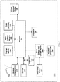
- the self-propelled device 100 preferably includes several interconnected subsystems and modules.
- a processor 114 may execute programmatic instructions from a program memory 104.
- the instructions stored in the program memory 104 may be changed, for example to add features, correct flaws, and/or modify device behavior.
- the program memory 104 may store programming instructions that are communicative or otherwise operable with software on a linked controller device.
- the processor 114 may execute different sets of programming instructions in order to alter the manner in which the self-propelled device 100 interprets or otherwise responds to control inputs from the linked controller.
- a wireless communication port 110 in conjunction with a communication transducer 102, preferably exchanges data between the processor 114 and other external devices.
- the data exchanges may provide communications, control, logical instructions, state information, and/or updates for the program memory 104.
- the processor 114 may generate output corresponding to state and/or position information, communicated to the linked controller via the wireless communication port 110.
- the mobility of the self-propelled device 100 may limit hard-wired connections.
- connection may be understood to mean a logical connection, such as a wireless link made without a physical connection to the self-propelled device 100.
- the wireless communication port 110 preferably implements the communication protocol and the transducer 102 is preferably an antenna suitable for transmission and reception of radio signals. Other wireless communication mediums and protocols may also be used in alternative implementations.
- Sensors 112 may transmit information about the surrounding environment and condition to the processor 114.
- the sensors 112 may include inertial measurement devices, including a three-axis gyroscope, a three-axis accelerometer, and/or a three-axis magnetometer.
- the sensors 114 may provide input to enable the processor 114 to maintain awareness of the device's orientation and/or position relative to an initial reference frame after the device 100 initiates movement. Also, the sensors 112 may include instruments for detecting light, temperature, humidity, and/or measuring chemical concentrations or radioactivity.
- a state/variable memory 106 preferably stores information about the present state of the system, including, for example, position, orientation, rates of rotation, and/or translation about each axis.
- the state/variable memory 106 may also store information corresponding to an initial reference frame of the device 100 upon, for example, the device being put in use (e.g., the device being switched on), as well as position and orientation information once the device is in use.
- the device 100 may utilize information of the state/variable memory 106 in order to maintain position and orientation information of the device once the device moves.
- a clock 108 preferably provides timing information to the processor 114 by implementing a time-base for measuring intervals and rates of change.
- the clock 108 may provide day, date, year, time, and/or alarm functions.
- the clock 108 may allow the self-propelled device 100 to sound an alarm or alert at pre-set times.
- An expansion port 120 preferably provides a connection for addition of accessories or devices.
- the expansion port 120 may provide for future expansion, as well as flexibility to add options or enhancements.
- the expansion port 120 may be used to add peripherals, sensors, processing hardware, storage, displays, or actuators to the basic self-propelled device 100.
- the expansion port 120 may provide an interface capable of communicating with a suitably configured component using analog or digital signals.
- the expansion port 120 may provide electrical interfaces and protocols that are standard or well-known.
- the expansion port 120 may implement an optical interface.
- Example interfaces appropriate for the expansion port 120 may include the universal serial bus (USB), inter-integrated circuit bus (I2C), serial peripheral interface (SPI), and/or ethernet.
- a display 118 may be included to present information to outside devices or users.
- the display 118 may present information in a variety of forms.
- display 118 may produce light in colors and patterns, sound, vibration, music, and/or combinations of sensory stimuli.
- the display 118 may operate in conjunction with actuators 126 to communicate information from physical movements of device 100.
- the device 100 may be made to emulate a human head, nod and/or shake to communicate "yes" or "no.”
- the display 118 may be an emitter of light, either in the visible or invisible range. Invisible light in the infrared or ultraviolet range may be useful, for example, to send information invisible to human senses, but available to specialized detectors.
- the display 118 may include an array of light emitting diodes (LEDs) emitting various light frequencies and arranged such that their relative intensity is variable and the light emitted is blended to form color mixtures.
- LEDs light emitting diodes
- the display 118 may include an LED array comprising several LEDs, each emitting a human-visible primary color.
- the processor 114 may vary the relative intensity of each of the LEDs to produce a wide range of colors.
- Primary colors of light are those in which a few colors may be blended in different amounts to produce a wide gamut of apparent colors.
- Many sets of primary colors are known, including, for example, red/green/blue, red/green/blue/white, and red/green/blue/amber.
- red, green and blue LEDs together may define a usable set of three available primary-color devices comprising the display 118.
- other sets of primary colors and white LEDs may be used.
- the display 118 may further include an LED used to indicate a reference point on the device 100 for alignment.
- a power cell 124 may store energy for operating the electronics and electromechanical components of the device 100.
- the power cell 124 may be a rechargeable battery.
- an inductive charge port 128 may allow for recharging the power cell 124 without a wired electrical connection.
- the inductive charge port 128 may accept magnetic energy and convert it to electrical energy to recharge the power cell 124.
- the charge port 128 may also provide a wireless communication interface with an external charging device.
- a deep sleep sensor 122 may be included to place the self-propelled device 100 into a very low power or "deep sleep” mode where most of the electronic devices use no battery power. This may be useful for long-term storage or shipping.
- the deep sleep sensor 122 may be non-contact in that it senses through the housing of the device 100 without a wired connection.
- the deep sleep sensor 122 may be a Hall-effect sensor mounted so that an external magnet may be applied at a pre-determined location on the device 100 to activate a deep sleep mode.
- Drive actuators 126 may be included to convert electrical energy into mechanical energy for various uses.
- a primary use of the drive actuators 126 may be to propel and steer the self-propelled device 100. Movement and steering actuators may also be referred to as a drive system or traction system.
- the drive system may move the device 100 in rotation and translation, under control of the processor 114.
- Examples of drive actuators 126 may include, without limitation, wheels, motors, solenoids, propellers, paddle wheels, and/or pendulums.
- the drive actuators 126 may include two parallel wheels, each mounted to an axle connected to an independently variable-speed motor through a reduction gear system. Thus, the speeds of the two drive motors may be controlled by the processor 114.
- the drive actuators 126 may produce a variety of movements in addition to merely rotating and translating the self-propelled device 100.
- the drive actuators 126 may allow the device 100 to execute communicative or emotionally evocative movements, including emulation of human gestures, for example, head nodding, shaking, trembling, spinning, and/or flipping.
- the processor 114 may coordinate the drive actuators 126 with the display 118.
- the processor 114 may provide signals to the drive actuators 126 and the display 118 to cause the device 100 to spin or tremble and simultaneously emit patterns of colored light.
- the device 100 may emit light and/or sound patterns synchronized with movements.
- the self-propelled device 100 may be used as a controller for other network-connected devices.
- the device 100 may contain sensors and wireless communication capability, and so it can perform a controller role for other devices.
- the self-propelled device 100 may be held in the hand and used to sense gestures, movements, rotations, combination inputs, etc.
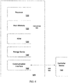
- FIG. 3 is an example conventional schematic depiction of a self-propelled device 214 under control of a controller device 208, such as a smart phone or tablet computing device. More specifically, the self-propelled device 214 may be controlled in its movement by programming logic and/or controls that can originate from the controller device 208. The self-propelled device 214 may move under control of the computing device 208, which can be operated by a user 202. The computing device 208 may wirelessly communicate control data 204 to the self-propelled device 214 using a standard or proprietary wireless communication protocol. In variations, the self-propelled device 214 may be at least partially self-controlled, utilizing sensors and internal programming logic to control the parameters of its movement (e.g., velocity, direction, etc.).
- the parameters of its movement e.g., velocity, direction, etc.
- the self-propelled device 214 may communicate data relating to the device's position and/or movement parameters for the purpose of generating or alternating content on the computing device 208.
- the self-propelled device 214 may control aspects of the computing device 208 by way of its movements and/or internal programming logic.
- the self-propelled device 214 may have multiple modes of operation, including those of operation in which the device is controlled by the computing device 208, is a controller for another device (e.g., another self-propelled device or the computing device 208), and/or is partially or wholly self-autonomous.
- the self-propelled device 214 and the computing device 208 may share a computing platform on which programming logic is shared in order to enable the user 202 to operate the computing device 208 and generate multiple kinds of input, including simple directional input, command input, gesture input, motion and/or other sensory input, voice input, or combinations thereof, enable the self-propelled device 214 to interpret input received from the computing device 208 as a command or set of commands, and/or enable the self-propelled device 214 to communicate data regarding that device's position, movement, and/or state in order to effect a state on the computing device 208 (e.g., display state, such as content corresponding to a controller-user interface).
- the self-propelled device 214 may include a programmatic interface that facilitates additional programming logic and/or instructions for using the device.
- the computing device 208 may execute programming that is communicative with the programming logic on the self-propelled device 214.
- the self-propelled device 214 includes an actuator or drive mechanism causing motion or directional movement.
- the self-propelled device 214 may be referred to by a number of related terms and phrases, including controlled device, robot, robotic device, remote device, autonomous device, and remote-controlled device.
- the self-propelled device 214 may be structured to move and be controlled in various media. For example, the self-propelled device 214 may move through media such as flat surfaces, sandy surfaces, and/or rocky surfaces.
- the self-propelled device 214 preferably corresponds to a spherical object that can roll and/or perform other movements such as spinning.
- the self-propelled device 214 preferably includes an external accessory 216 magnetically coupled to the self-propelled device 214 via magnetic coupling through the spherical housing of the device.
- the self-propelled device 214 may correspond to a radio-controlled aircraft, such as an airplane, helicopter, hovercraft, and/or balloon.
- the device 214 may correspond to a radio controlled watercraft, such as a boat or submarine. Numerous other variations may also be implemented, such as those in which the device 214 is a robot.
- the self-propelled device 214 may include a sealed hollow envelope, substantially spherical in shape, capable of directional movement by action of actuators inside the envelope.
- the self-propelled device 214 may communicate with the computing device 208 using network communication links 210, 212.
- One link 210 may transfer data from the computing device 208 to self-propelled device 214.
- the other link 212 may transfer data from the self-propelled device 214 to the computing device 208.
- the links 210, 212 may be separate unidirectional links or a single bi-directional communication link communicating in both directions.
- the links 210, 212 may not be identical in type, bandwidth, and/or capability.
- the link 210 from the computing device 208 to the self-propelled device 214 may be capable of a higher communication rate and bandwidth compared to the link 212. In some situations, only one link 210 or 212 may be established. Communication may then be unidirectional.
- the computing device 208 may correspond to any device comprising at least a processor and communication capability suitable for establishing at least unidirectional communications with the self-propelled device 214.
- Examples of such devices may include, without limitation mobile computing devices (e.g., multifunctional messaging/voice communication devices such as smart phones), tablet computers, portable communication devices, and/or personal computers.
- the user 202 may interact with the self-propelled device 214 via the computing device 208 in order to control the self-propelled device 214 and/or to receive feedback or interaction on the computing device 208 from the self-propelled device 214.
- the user 202 may specify input 204 through various mechanisms of the computing device 208. Examples of such inputs may include text entry, voice command, touching a sensing surface or screen, physical manipulations, gestures, taps, shaking, and combinations thereof.
- the user 202 may interact with the computing device 208 in order to receive feedback 206.
- the feedback 206 may be generated by the computing device 208 in response to user input.
- the feedback 206 may also be based on data communicated from the self-propelled device 214 to the computing device 208, regarding, for example, the self-propelled device's position or state. Examples of feedback 206 may include text display, graphical display, sound, music, tonal patterns, modulation of color or intensity of light, haptic, vibrational, and/or tactile stimulation.
- the feedback 206 may be combined with input that is generated on the computing device 208.
- the computing device 208 may thereby output content that is modified to reflect position or state information communicated from the self-propelled device 214.
- the computing device 208 and/or the self-propelled device 214 may thus be configured such that user input 204 and feedback 206 maximize usability and accessibility for the user 202, who may have limited sensing, thinking, perception, motor, and/or other abilities. This allows a user 202 with handicaps or special needs to operate the system 200.
- FIG. 4 schematically shows another conventional example of a self-propelled device 300.
- the self-propelled device 300 may be of a size and weight allowing it to be easily grasped, lifted, and/or carried in an adult human hand.
- the self-propelled device 300 may include a spherical housing 302 with an outer surface that makes contact with an external surface as the device moves by rolling.
- the spherical housing 302 include an inner surface 304 and several mechanical and electronic components enclosed by the inner surface of the spherical housing.
- the spherical housing 302 may be composed of a material that transmits signals used for wireless communication, yet are impervious to moisture and dirt.
- the spherical housing 302 may further be durable, washable, and/or shatter-resistant.
- the spherical housing 302 may also be structured to enable transmission of light and textured to diffuse the light.
- the spherical housing 302 may be a sealed polycarbonate plastic.
- the spherical housing 302 may comprise two hemispherical shells with an associated attachment mechanism, such that the spherical housing may be opened to allow access to internal electronic and mechanical components.
- spherical housing 302 for processing, wireless communication, propulsion, and/or other functions (collectively referred to as an "interior mechanism").
- examples may include a drive system 301 enabling the device 300 to propel itself.
- the drive system 301 may be coupled to processing resources and other control mechanisms.
- a carrier 314 serves as an attachment point and support for components of the drive system 301.
- the components of the drive system 301 may not be rigidly attached to the spherical housing 302. Instead, the drive system 301 may include a pair of rollers 318, 320 that are in frictional contact with the inner surface 304 of the spherical housing 302.
- the carrier 314 may be in mechanical and/or electrical contact with an energy storage component 316.
- the energy storage component 316 may provide a reservoir of energy to power the device 300 and its associated electronic components.
- the energy storage component 316 may be replenished through an inductive charge port 326.
- the energy storage component 316 may be a rechargeable battery.
- Such a battery may comprise lithium-polymer cells. Other suitable rechargeable battery chemistries/mechanisms may also be used.
- the carrier 314 may provide a mounting location for most of the internal components, including printed circuit boards for electronic assemblies, sensor arrays, antennas, and connectors, as well as providing a mechanical attachment point for internal components.
- the drive system 301 may include motors 322, 324 and wheels 318, 320.
- the motors 322, 324 may connect to the wheels 318, 320, respectively, each through an associated shaft, axle, and gear drive (not shown).
- the perimeter of wheels 318, 320 may mechanically contact the inner surface 304 at essentially two points. These points may provide the drive mechanism of the spherical housing 302, or ball, and may be coated with a material to increase friction and reduce slippage between the wheels 318, 320 and the inner surface 304.
- the wheels 318, 320 may include silicone rubber tires.
- a biasing mechanism 315 may actively force the wheels 318, 320 against the inner surface 304.
- a spring 312 and a spring end 310 may comprise the biasing mechanism 315. More specifically, the spring 312 and the spring end 310 may be positioned to contact the inner surface 304 at a point diametrically opposed to the wheels 318, 320.
- the spring 312 and the spring end 310 may provide additional contact force to reduce slippage of the wheels 318, 320, particularly in situations where the interior mechanism is not positioned with the wheels at the bottom and where gravity does not provide adequate force to prevent the drive wheels 318, 320 from slipping.
- the spring 312 may provide a force to press the wheels 318, 320 and the spring end 310 against the inner surface 304.
- the spring end 310 may provide near-frictionless contact with the inner surface 304.
- the spring end 310 may be a rounded surface configured to mirror a low-friction contact region at all contact points with the inner surface 304.
- the rounded surface may include one or more bearings to further reduce friction at the contact point where spring end 310 moves along inner surface 304.
- the spring 312 and the spring end 310 may be made of a non-magnetic material to avoid interference with sensitive magnetic sensors.
- the spring end 310 may include one or more magnetic components to magnetically couple to an external accessory device 330.
- the spring 312 may have a spring constant such that the wheels 318, 320 and the spring end 310 may be constantly engaged to the inner surface 304 of the spherical housing 302. As such, much of the power from the motors 322, 324 may be transferred directly to rotating the spherical housing 302, as opposed to causing the internal components (e.g., the biasing mechanism 315 and internal drive system 301) to slant or pitch.
- the internal components e.g., the biasing mechanism 315 and internal drive system 301
- motion of the self-propelled device 300 may be caused, at least partially, by pitching the internal components (and therefore the center of mass of the device), motion may also be directly caused by active force of the wheels 318, 320 against the inner surface 304 of the spherical housing 302 (via the biasing mechanism 315) and direct transfer of electrical power from the motors 322, 324 to the wheels 318, 320.
- the pitch of the biasing mechanism 315 may be substantially reduced, and remain substantially constant (e.g., substantially perpendicular to the external surface on which the self-propelled device 300 moves).
- the pitch of the biasing mechanism 315 may increase (e.g., to over 45 degrees) during periods of hard acceleration or deceleration.
- the pitch of the biasing mechanism 315 may remain stable or subtly vary (e.g., within 10° to 15°).
- the spring end 310 may be formed of a magnetic metal attracted to a magnet. Such metals may include iron, nickel, cobalt, gadolinium, neodymium, samarium, and/or other metal alloys containing proportions of these metals. Alternatively, the spring end 310 may include a substantially frictionless contact portion, in contact with the inner surface 304 of the spherical housing 302, and a magnetically interactive portion, in contact or non-contact with the inner surface 304, including the above metals or metal alloys.
- the substantially frictionless contact portion can be comprised of an organic polymer such as a thermoplastic or thermosetting polymer.
- the spring end 310 may be a magnet, such as a polished neodymium permanent magnet.
- the spring end 310 may produce a magnetic field extending beyond the outer surface of the spherical housing 302 to magnetically couple with the external accessory device 330.
- the spring end 310 may be comprised of a substantially frictionless contact portion and have a magnet included therein.
- the magnetic component of the self-propelled device 300 may be included on any internal component, such as the spring 312 or the carrier 314, or an additional component coupled to the biasing mechanism 315 or the carrier.
- the external accessory device 330 may include a magnetic component 332 to magnetically couple with the biasing mechanism 315 (e.g., the spring end 310).
- the magnetic component 332 may comprise a permanent magnet, such as a neodymium magnet.
- the magnetic component 332 may magnetically couple to the spring end 310. As such, the magnetic field produced by the magnetic component 332 may extend through the spherical housing 302 to remain in magnetic contact with the spring end 310.
- the magnetic component 332 of the external accessory device 330 may comprise a magnetic metal attracted to a magnet comprising the spring end 310.
- One or more of the spring ends 310 and the magnetic components may comprise any number of electro and/or permanent magnets. Such magnets may be irregular in shape to provide added magnetic stability upon motion of the self-propelled device 300.
- the magnetic component 332 of the external accessory device 330 may be a single magnetic strip or multiple magnetic strips including one or more tributary strips to couple with a single or multiple correspondingly shaped magnets on the spring end 310. Multiple magnets may be dispersed through the external accessory device 330 and the spring end 310 to provide additional stability.
- the spring end 310 and external accessory device 330 may be in a stable magnetically repulsive state as the self-propelled device 300 moves.
- Either the magnetic component 332 or the spring end 310 may further include a superconductor material to substantially eliminate dynamic instability of a repelling magnetic force and allow stable magnetic levitation of the external accessory device 330 in relation to the spring end 310 while the spherical housing 302 slides therebetween.
- a diamagnetic material may be included in one or more of the self-propelled device 300, spring end 310, and/or the external accessory device 330 for stable magnetic levitation.
- the self-propelled device 300 may maneuver in any direction with the external accessory device 330 remaining in a substantially constant position along a vertical axis of the self-propelled device.
- the external accessory device 330 may be in the form of any shape and may comprise any suitable material.
- a contact surface 334 of the external accessory device 330, or a surface closest to the outer surface of the spherical housing 302 (during magnetic interaction), may correspond to the outer surface of the spherical housing 304.
- Both the spherical housing 302 of the self-propelled device 300 and the external accessory device 330, namely the contact surface 334 may have substantially equivalent radii of curvature. This radius may be on the order of 10 cm to 30 cm. However, the radius may one meter up to the size of a human transportation vehicle and beyond.
- magnetic coupling or interaction may be achieved using powerful electromagnets disposed within the self-propelled device 300 to couple with the external accessory device 330, which may perform actions, carry payload, include a novel design, represent a character or figure, etc.
- the contact surface 334 of the external accessory device 330 may be formed or coated with a substantially frictionless material, such as a synthetic compound or suitable polymer.
- a substantially frictionless material such as a synthetic compound or suitable polymer.
- suitable compounds may include polytetrafluoroethylene (PTFE), polyoxymethylene (POM), ultra-repellant surfaces, and/or liquid-impregnated surfaces and materials, such as slippery liquid infused porous surface (SLIPS).
- SLIPS slippery liquid infused porous surface
- substantially frictionless surfaces or coatings may include "ceramic alloys," or “cermets,” which may be created by combining a metal alloy with a ceramic compound.
- a metal/ceramic alloy comprised of boron, aluminum, and magnesium may be combined with the cermetic compound of titanium diboride (TiB 2 ) to provide a near-frictionless coating for the contact surface 334 of the external accessory device 330.
- the outer surface of the spherical housing 302 may comprise of any of the above substantially frictionless coatings or compounds discussed with respect to the contact surface 334 of the external accessory device 330. Any combination of substantially frictionless coatings or compounds may be incorporated with respect to the outer surface of the spherical housing 302 and the contact surface 334 of the external accessory device 330.
- the spherical housing 302 may be formed to include an inner surface 304 more conducive to providing added friction using, for example, a rubber compound or other suitable synthetic compound, such as a silicone.
- the spherical housing 302 may include an outer surface having near-frictionless properties using coatings or compounds, as discussed above.
- the external accessory device 330 When the self-propelled device 300 moves, the external accessory device 330 preferably remain magnetically coupled to the spring end 310 at a substantially constant position on top of the self-propelled device 300.
- the biasing mechanism 315 may have a variable tilt angle relative to the plane of motion that remains somewhat minimal, but in most cases, does not typically exceed 45°, except during periods of relatively extreme acceleration or deceleration. However, during continuous and stable maneuvering of the self-propelled device 300, the tilt of the biasing mechanism 315 may be closer to naught, or within 10°.
- the azimuth may vary at any angle depending on independent power transferred from the motors 322, 344 to the wheels 318, 320.
- FIG. 5 illustrates an example conventional technique for causing motion of a self-propelled spherical device 400.
- the self-propelled device 400 may have a sensor platform 404, center of rotation 402 and center of mass 406 and contact a planar surface 412.
- the drive mechanism for the device 400 may comprises two independently-controlled wheeled actuators 408 in contact with the inner surface of the spherical housing of the device 400.
- the displacement of the center of mass 406 relative to center of rotation 402 may be maintained by action of wheeled actuators 408.
- the displacement of the center of mass 406 relative to center of rotation 402 may be difficult to measure. Thus, it may be difficult to obtain feedback for a closed-loop controller to maintain constant velocity.
- the displacement may be proportional to the tilt angle 410 between the sensor platform 404 and the planar surface 412.
- the tilt angle 410 may be sensed or estimated from a variety of sensor inputs. Therefore, the speed controller for the device 400 may be implemented to use the tilt angle 410 to regulate speed for the wheeled actuators 408 and maintain a constant speed across the planar surface 412.
- the speed controller may determine the desired angle 410 to produce the desired speed and the desired angle set-point may be an input to a closed loop controller regulating the drive mechanism.
- This speed control technique may be extended to control turns and rotations of the spherical device 400 with feedback of appropriate sensed angles and angular rates.
- FIG. 6 schematically shows a computer system upon which the above examples may be implemented.
- One or more components discussed with respect to the system 100 of FIG. 2 may be performed by the system 500 of FIG. 6 .
- the system 100 may also be implemented using a combination of multiple computer systems.
- the computer system 500 may include processing resources 510, a main memory 520, read only memory (ROM) 530, a storage device 540, and a communication interface 550.
- the computer system 500 may include at least one processor 510 and a main memory 520, such as a random access memory (RAM) or other dynamic storage device with instructions 522 to be executed by the processor 510.
- the main memory 520 also may store temporary variables or other intermediate information during execution of instructions executed by the processor 510.
- the computer system 500 may also include a read only memory (ROM) 530 or other static storage device for storing static information and instructions for the processor 510.
- ROM read only memory
- a storage device 540 such as a magnetic disk or optical disk, may store information and instructions.
- the storage device 540 may correspond to a computer-readable medium that triggers logic for maneuvering the self-propelled device 100, 200, 300, 400.
- the communication interface 550 enables the computer system 500 to communicate with a controller device 580 via an established network link 552 (wireless and/or hardwire). Using the network link 552, the computer system 500 may receive command instructions for maneuvering the self-propelled device 100, 200, 300, 400.
- the computer system 500 may implement the techniques described herein. Those techniques may be performed by the computer system 500 in response to the processor 510 executing one or more sequences of one or more instructions contained in the main memory 520. Such instructions may be read into the main memory 520 from another machine-readable medium, such as the storage device 540. Execution of the instructions contained in the main memory 520 may cause the processor 510 to perform the process steps described herein. Hard-wired circuitry may be used in place of, or in combination with, software instructions to implement examples described herein. Thus, the examples described are not limited to any specific combination of hardware circuitry and software.
- the spherical shape of this concept may transform the way autonomous or any vehicles move.
- the spherical, shape may positively contribute to the safety, maneuverability, and comfort to match the demands of autonomous and any mobility.
- the multi-orientation tires may move in all directions, contributing to safety and comfort for passengers, as well as coping with any space limitations.
- Active anti-sliding technology may allow the tire to move as needed to reduce sliding from potential hazards, such as black ice or sudden obstacles.
- the spherical shape may provide a smooth ride to address passenger comfort.
- the spherical shape may create a fluid, lateral movement to help the car overtake any obstacles without changing its driving direction. Further, because 360 degree turns are possible with the spherical shape, anticipated parking constrictions may be overcome, as less space is needed for cars fitted with spherical tires to pull into parking spots. Assuming public parking areas play the same role in the future, this could significantly increase the capacity of public parking areas without increasing their overall size.
- a spherical tire/drive apparatus in accordance with the present invention may rely on magnetic levitation to carry the load of a vehicle.
- a spherical tire may be suspended from the vehicle by magnetic fields similar to magnetic levitation trains, which result in increased comfort and reduced noise for users.
- Such an apparatus may allow total integration of moving parts into the body of the spherical tire and/or the body of the vehicle (e.g., no moving parts or critical surfaces exposed to the environment). Further, a recharging system, through magnetic induction, may be totally isolated from the external environment.
- the apparatus may simplify manufacturing and assembly as well as eliminate some components entirely, such as rims, steering system, axles, shock absorbers, springs, etc., thereby also reducing weight and cost.
- the magnetic levitation and control may eliminate all direct contact between the vehicle and the road thereby mitigating vibration, noise, and other undesired effects of direct contact.
- the spherical tire may have several spherical tread layers, which may or may not mimic the functionality of conventional tire treads.
- the structure interior to the spherical tread may be an auxetic or normal foam material which is strong enough to take the load of the vehicle, but flexible enough to allow the tread to deform and generate an appropriate contact patch with the road.
- a magnetic material layer and/or a diamagnetic layer may be located interior to the spherical tread structure for providing the levitation and control between tires and the vehicle.
- the vehicle may be permanently levitated away from the spherical tires or the alternate levitation, so that the vehicle/tires expend no energy when the vehicle is at rest and unused.
- Diamagnetic materials may generate a magnetic field only if they themselves are brought into an active magnetic field.
- One part or all of the energy for the magnetic fields may come from a battery inside the spherical tire or a battery in the vehicle.
- the battery in the spherical tire may be charged and recharged by inductive transfer from a battery in the vehicle.
- An electric motor inside the spherical tire may provide the tire and the vehicle mobility, similar to that described above.
- magnetic pulses may emote the tire and vehicle.
- the load bearing portion of the spherical tire may be constructed of graphene layers or layers of carbon-fiber.
- a support assembly 1000 for a vehicle 901 in accordance with the present invention includes at least two spherical tires 1010, a drive system 1100 emoting the tires 1010 such that the vehicle 901 may be transported along a road surface.
- the vehicle 901 may be a car, golf cart, motorcycle, military transport, etc.
- the drive system 110 preferably magnetically levitates the vehicle 901 a first predetermined distance from the tires 1010 and magnetically maintains the drive system 1100 at a constant orientation relative to the road surface.
- a first part 1110 of the drive system 1100 may magnetically levitate itself a second predetermined distance from an inner surface 1020 of the tires 1010 such that the part 1110 is entirely enclosed within an interior space 1025 of each tire 1010.
- Another part 1120 of the drive system 1100 may magnetically levitate the vehicle 901 the first predetermined distance from the tires 1010.
- Either part 1110 or 1120 of the drive system 1100 may be a magnetically passive component that responds to variations of a magnetic field.
- a corresponding other part 1120 or 1110 of the drive system 1100 may be a magnetically active component that generates variations in the magnetic field.
- Either component 1110, 1120 may itself generate a constant magnetic field.
- the spherical tires 1010 preferably include several spherical layers 1030. Some of the layers 1030 may function similarly to layers of a conventional pneumatic tire, such as the tread, the belts, the overlay, the carcass, etc. At least one of the layers 1035 may include a material responsive to a magnetic field variations such that each of the tires 1010 may be controllably rotated about a spherical center 1011 of the tires relative to the vehicle 901, the drive system 1100, and the road surface.
- Aqueous solutions of a variety of polar aprotic polymers exhibit a lower critical solution temperature (LCST).
- LCST critical solution temperature
- the intramolecular hydrogen bonding is preferred compared to the hydrogen bonding with water molecules. This leads to collapse of the polymer coils and a precipitation of the polymer from solution. This phase transition is reversible so that the polymer redissolves when the temperature is again decreased below the LCST.
- An example of an LCST polymer is poly(N-isopropyl acrylamide) (PNIPAM).
- PNIPAM poly(N-isopropyl acrylamide)
- Aqueous solutions of this polymer exhibit an LCST transition at about 33 °C.
- LCST polymers with elastomers offer the possibility of better control of elastomer performance in a variety of applications where the elastomer is exposed to water.
- Simple mixing of an LCST polymer with an elastomer results in a compound that will experience macrophase separation due to the lack of covalent bonds between the LCST polymer and the elastomer. Such a macrophase separation may have a detrimental effect on tread compound properties.
- the spherical tread layer 1030 may include a rubber composition comprising: a copolymer comprising a polymeric backbone chain derived from a monomer comprising at least one conjugated diene monomer and optionally at least one vinyl aromatic monomer; and polymeric sidechains bonded to the backbone chain, the sidechains comprising a polymer capable of exhibiting a lower critical solution temperature (LCST); optionally, at least one additional diene based elastomer; and a filler selected from the group consisting of carbon black and silica.
- LCST critical solution temperature
- the rubber composition may include a copolymer comprising a polymeric backbone chain derived from a monomer comprising at least one conjugated diene monomer and optionally at least one vinyl aromatic monomer; and polymeric sidechains bonded to the backbone chain, the sidechains comprising a polymer capable of exhibiting a lower critical solution temperature (LCST).
- LCST critical solution temperature
- the copolymer may have the structure of Formula I: where X is a polymer derived from a monomer comprising at least one conjugated diene monomer and optionally at least one vinyl aromatic monomer; Z is a polymer capable of exhibiting a lower critical solution temperature (LCST); Y is a divalent group bonded to both X and Z; and n is the number of - ⁇ Y-Z] groups bonded to X.
- X is a polymer derived from a monomer comprising at least one conjugated diene monomer and optionally at least one vinyl aromatic monomer
- Z is a polymer capable of exhibiting a lower critical solution temperature (LCST)
- Y is a divalent group bonded to both X and Z
- n is the number of - ⁇ Y-Z] groups bonded to X.
- the polymer X is a diene based elastomer comprising at least one carbon-carbon double bond.
- rubber or elastomer containing olefinic unsaturation or "diene based elastomer” as used herein are equivalent and are intended to include both natural rubber and its various raw and reclaim forms as well as various synthetic rubbers.
- the terms “rubber” and “elastomer” may be used interchangeably, unless otherwise prescribed.
- the terms “rubber composition,” “compounded rubber” and “rubber compound” are used interchangeably to refer to rubber which has been blended or mixed with various ingredients and materials and such terms are well known to those having skill in the rubber mixing or rubber compounding art.
- Representative synthetic rubbers are the homopolymerization products of butadiene and its homologues and derivatives, for example, methylbutadiene (i.e., isoprene), dimethylbutadiene and pentadiene as well as copolymers such as those formed from butadiene or its homologues or derivatives with other unsaturated monomers.
- methylbutadiene i.e., isoprene
- dimethylbutadiene and pentadiene as well as copolymers such as those formed from butadiene or its homologues or derivatives with other unsaturated monomers.
- acetylenes for example, vinyl acetylene
- olefins for example, isobutylene, which copolymerizes with isoprene to form butyl rubber
- vinyl compounds for example, acrylic acid, acrylonitrile (which polymerize with butadiene to form NBR), methacrylic acid and styrene, the latter compound polymerizing with butadiene to form SBR, as well as vinyl esters and various unsaturated aldehydes, ketones and ethers, e.g., acrolein, methyl isopropenyl ketone and vinylethyl ether.
- synthetic rubbers include neoprene (polychloroprene), polybutadiene (including cis-1,4-polybutadiene), polyisoprene (including cis-1,4-polyisoprene), butyl rubber, halobutyl rubber such as chlorobutyl rubber or bromobutyl rubber, styrene/isoprene/butadiene rubber, copolymers of 1,3-butadiene or isoprene with monomers such as styrene, acrylonitrile and methyl methacrylate, as well as ethylene/propylene terpolymers, also known as ethylene/propylene/diene monomer (EPDM), and in particular, ethylene/propylene/ dicyclopentadiene terpolymers.
- neoprene polychloroprene
- polybutadiene including cis-1,4-polybutadiene
- rubbers which may be used include alkoxy-silyl end functionalized solution polymerized polymers (SBR, PBR, IBR and SIBR), silicon-coupled and tin-coupled star-branched polymers.
- SBR alkoxy-silyl end functionalized solution polymerized polymers
- PBR polybutadiene
- SIBR silicon-coupled and tin-coupled star-branched polymers.
- the preferred rubber or elastomers are polyisoprene (natural or synthetic), polybutadiene and SBR.
- an emulsion polymerization derived styrene/butadiene might be used having a relatively conventional styrene content of 20 to 28 percent bound styrene or, for some applications, an E-SBR having a medium to relatively high bound styrene content, namely, a bound styrene content of 30 to 45 percent.
- E-SBR emulsion polymerization prepared E-SBR
- styrene and 1,3-butadiene are copolymerized as an aqueous emulsion.
- the bound styrene content can vary, for example, from 5 to 50 percent.
- the E-SBR may also contain acrylonitrile to form a terpolymer rubber, as E-SBAR, in amounts, for example, of 2 to 30 weight percent bound acrylonitrile in the terpolymer.
- Emulsion polymerization prepared styrene/butadiene/acrylonitrile copolymer rubbers containing 2 to 40 weight percent bound acrylonitrile in the copolymer may also be contemplated as diene based rubbers for use in this invention.
- the solution polymerization prepared SBR (S-SBR) may have a bound styrene content in a range of 5 to 50, preferably 9 to 36, percent.
- the S-SBR can be conveniently prepared, for example, by organo lithium catalyzation in the presence of an organic hydrocarbon solvent.
- cis 1,4-polybutadiene rubber may be used.
- BR cis 1,4-polybutadiene rubber
- Such BR may be prepared, for example, by organic solution polymerization of 1,3-butadiene.
- the BR may be conveniently characterized, for example, by having at least a 90 percent cis 1,4-content.
- the term "phr” as used herein, refers to "parts by weight of a respective material per 100 parts by weight of rubber, or elastomer.”
- the polymer Z having a lower critical solution temperature may include homopolymers and copolymers of various second monomers known to have LCST behavior, including but not limited to polymers of: acrylamides and substituted acrylamides, methacrylamides and substituted methacrylamids, acrylic acids and substituted acrylic acids, methacrylic acids and substituted methacrylic acids, vinyl alkyl ethers and substituted vinyl alkyl ethers, vinyl caprolactams and substituted vinyl caprolactams, and other monomers known to lead to polymers with LCST behavior, such as oligo(ethylene glycol) methacrylate and 2-(2-methoxyethoxy) ethyl methacrylate, and the like.
- acrylamides and substituted acrylamides methacrylamides and substituted methacrylamids
- acrylic acids and substituted acrylic acids methacrylic acids and substituted methacrylic acids
- vinyl alkyl ethers and substituted vinyl alkyl ethers vinyl caprolact
- LCST critical solution temperature
- the polymer Z is a polymer of a second monomer of Formula II: where R 1 and R 2 are independently selected from the group consisting of hydrogen, C2 to C6 linear alkyl, C2 to C6 branched alkyl, and C3 to C6 cycloalkyl, with the proviso that at least one of R 1 and R 2 is not hydrogen.
- Z may be Formula (III) where R 1 and R 2 are independently selected from the group consisting of hydrogen, C2 to C6 linear alkyl, C2 to C6 branched alkyl, and C3 to C6 cycloalkyl, with the proviso that at least one of R 1 and R 2 is not hydrogen, and m is the degree of polymerization of the hydrocarbon chain.
- the polymer Z is a polymer of an N-substituted acrylamide derivative.
- the polymer Z is a polymer of N-isopropylacrylamide, N-cyclopropylacrylamide, or N, N-diethylacrylamide.
- the polymer Z capable of exhibiting a lower critical solution temperature has a weight average molecular weight ranging from 500 to 20000 g/gmol.
- the polymer Z may be capable of exhibiting a lower critical solution temperature and have a lower critical solution temperature in a range of from 0°C to 100°C.
- the copolymer comprises from 1 to 20 weight percent Z.
- Y may be a divalent group bonded to both X and Z.
- Y is sulfur or oxygen.
- Y is sulfur.
- Y originates as a terminal functional group of the polymer Z capable of reacting with a carbon-carbon double bond of the polymer X.
- the terminal functional group is a thiol group.
- Such a terminal functional group may be incorporated into the polymer Z during polymerization, for example, through use of a suitable chain transfer agent or terminating agent as is known in the art.
- the number n of ⁇ -Y-Z] groups may be bonded to X ranges from 2 to 30 in a given copolymer molecule.
- the copolymer may be produced by various methods.
- the copolymer may be produced by functionalizing the polymer X with side chains of LCST polymer Z to produce a graft copolymer with an elastomer backbone and LCST polymer sidechains.
- a convenient way for the functionalization of a variety of elastomers is the thiol-ene reaction during which alkene moieties being present in the elastomers are transformed into thioethers by reaction with thiols. This reaction may proceed with vinyl groups as they are present in styrene-butadiene rubbers, butadiene rubbers, and polyisoprene rubbers.
- the LCST polymers may feature thiol end groups. These can be introduced by reaction of thiocarbonylthio endgroups with nucleophilic agents. Polymers exhibiting thiocarbonylthio end groups can be produced by reversible addition-fragmentation chain transfer (RAFT) polymerization.
- RAFT reversible addition-fragmentation chain transfer
- One reaction scheme describes the use of PNIPAM as LCST polymer, however, this invention is not limited to that as any LCST polymer with a reactive end group, which for example can be produced by RAFT polymerization, can be used for the functionalization of the elastomer.
- a first step of the method to produce the graft copolymer may be obtaining a first polymer comprising at least one carbon-carbon double bond.
- a second step of the method may be obtaining a second polymer.
- the second polymer may exhibit a lower critical solution temperature (LCST) and comprise a terminal functional group capable of reacting with the carbon-carbon double bond of the first polymer.
- LCST critical solution temperature
- the second polymer is obtained by polymerizing a second monomer in the presence of a thiocarbonylthio RAFT chain transfer agent to form a polymer comprising a terminal thiocarbonylthio group; and cleaving the terminal thiocarbonylthio group to a thiol group to form the second polymer comprising a terminal thiol group.
- the terminal functional group of the second polymer is incorporated in the second polymer during polymerization through the mechanism of reversible addition-fragmentation chain transfer (RAFT). More details of the RAFT polymerization mechanism may be found by reference to Moad et al., Aust. J. Chem. 2005, 58, 379-410 .
- RAFT polymerization of free-radical polymerizable monomers may be accomplished in the presence of a thiocarbonylthio RAFT chain transfer agent of Formula (IV): where R 3 is a free radical leaving group able to reinitiate polymerization, and Q is a functional group that influences the rate of radical addition and fragmentation.
- Suitable thiocarbonylthio RAFT chain transfer agents include dithioesters, trithiocarbonates, dithiocarbamates, and xanthates.
- the thiocarbonylthio chain transfer agent is a trithiocarbonate.
- the thiocarbonylthio chain transfer agent is selected from the group consisting of S-1-dodecyl-S-( ⁇ '-dimethyl- ⁇ "-acetic acid) trithiocarbonate and 4-cyano-4-dodecylsulfanylthiocarbonylsulfanyl-4-methyl butyric acid.
- the chain-terminated polymer Upon RAFT polymerization in the presence of a suitable thiocarbonylthio chain transfer agent, the chain-terminated polymer has the Formula (V): where P n represents the polymer chain exhibiting a LCST.
- the chain terminated polymer of formula V may then be reacted with a suitable nucleophile to cleave the C-S linkage to obtain a second polymer of formula (VI) having a terminal thiol group of Formula (VI): H-S-P n (VI)
- the chain terminated polymer of Formula V is treated by aminolysis to obtain the thiol-terminated polymer of Formula VI.
- a third step of the method may be reacting the second polymer with the first polymer to form a graft copolymer, the graft copolymer comprising a backbone derived from the first polymer and sidechains derived from the second polymer.
- a second polymer may be linked to the first polymer through reaction of a terminal functional group of the second polymer with the unsaturated carbon-carbon bond of the first polymer.
- the thiol-terminated second polymer may be reacted with the first polymer in the presence of a free-radical initiator via a thiol-ene reaction, see for example Macromolecules 2008, 41, 9946-9947 .
- the free-radical initiator is selected from the group consisting of 2,4,6-Trimethylbenzoyldiphenylphosphine oxide and azobisisobutyonitrile (AIBN).
- the rubber composition may optionally include, in addition to the copolymer comprising a polymer having a lower critical solution temperature (LCST), one or more rubbers or elastomers containing olefinic unsaturation.
- LCST lower critical solution temperature
- the phrases "rubber or elastomer containing olefinic unsaturation” or “diene based elastomer” are intended to include both natural rubber and its various raw and reclaim forms as well as various synthetic rubbers. In the description of this invention, the terms “rubber” and “elastomer” may be used interchangeably, unless otherwise prescribed.
- rubber composition refers to rubber which has been blended or mixed with various ingredients and materials and such terms are well known to those having skill in the rubber mixing or rubber compounding art.
- Representative synthetic polymers are the homopolymerization products of butadiene and its homologues and derivatives, for example, methylbutadiene, dimethylbutadiene and pentadiene as well as copolymers such as those formed from butadiene or its homologues or derivatives with other unsaturated monomers.
- acetylenes for example, vinyl acetylene
- olefins for example, isobutylene, which copolymerizes with isoprene to form butyl rubber
- vinyl compounds for example, acrylic acid, acrylonitrile (which polymerize with butadiene to form NBR), methacrylic acid and styrene, the latter compound polymerizing with butadiene to form SBR, as well as vinyl esters and various unsaturated aldehydes, ketones and ethers, e.g., acrolein, methyl isopropenyl ketone and vinylethyl ether.
- synthetic rubbers include neoprene (polychloroprene), polybutadiene (including cis-1,4-polybutadiene), polyisoprene (including cis-1,4-polyisoprene), butyl rubber, halobutyl rubber such as chlorobutyl rubber or bromobutyl rubber, styrene/isoprene/butadiene rubber, copolymers of 1,3-butadiene or isoprene with monomers such as styrene, acrylonitrile and methyl methacrylate, as well as ethylene/propylene terpolymers, also known as ethylene/propylene/diene monomer (EPDM), and in particular, ethylene/propylene/ dicyclopentadiene terpolymers.
- neoprene polychloroprene
- polybutadiene including cis-1,4-polybutadiene
- rubbers which may be used include alkoxy-silyl end functionalized solution polymerized polymers (SBR, PBR, IBR and SIBR), silicon-coupled and tin-coupled star-branched polymers.
- SBR alkoxy-silyl end functionalized solution polymerized polymers
- PBR polybutadiene
- SIBR silicon-coupled and tin-coupled star-branched polymers.
- the preferred rubber or elastomers are polyisoprene (natural or synthetic), polybutadiene and SBR.
- the at least one additional rubber may be of at least two of diene based rubbers.
- a combination of two or more rubbers may be cis 1,4-polyisoprene rubber (natural or synthetic, although natural is preferred), 3,4-polyisoprene rubber, styrene/isoprene/butadiene rubber, emulsion and solution polymerization derived styrene/butadiene rubbers, cis 1,4-polybutadiene rubbers and emulsion polymerization prepared butadiene/acrylonitrile copolymers.
- an emulsion polymerization derived styrene/butadiene might be used having a relatively conventional styrene content of 20 to 28 percent bound styrene or, for some applications, an E-SBR having a medium to relatively high bound styrene content, namely, a bound styrene content of 30 to 45 percent.
- E-SBR emulsion polymerization prepared E-SBR
- styrene and 1,3-butadiene are copolymerized as an aqueous emulsion.
- the bound styrene content can vary, for example, from 5 to 50 percent.
- the E-SBR may also contain acrylonitrile to form a terpolymer rubber, as E-SBAR, in amounts, for example, of 2 to 30 weight percent bound acrylonitrile in the terpolymer.
- Emulsion polymerization prepared styrene/butadiene/acrylonitrile copolymer rubbers containing 2 to 40 weight percent bound acrylonitrile in the copolymer are also contemplated as diene based rubbers for use in this invention.
- the solution polymerization prepared SBR (S-SBR) may have a bound styrene content in a range of 5 to 50, preferably 9 to 36, percent.
- the S-SBR may be prepared, for example, by organo lithium catalyzation in the presence of an organic hydrocarbon solvent.
- cis 1,4-polybutadiene rubber (BR) may be used.
- Such BR can be prepared, for example, by organic solution polymerization of 1,3-butadiene.
- the BR may be characterized, for example, by having at least a 90 percent cis 1,4-content.
- the rubber composition may also include up to 70 phr of processing oil.
- Processing oil may be included in the rubber composition as extending oil typically used to extend elastomers. Processing oil may also be included in the rubber composition by addition of the oil directly during rubber compounding.
- the processing oil used may include both extending oil present in the elastomers, and process oil added during compounding.
- Suitable process oils include various oils as are known in the art, including aromatic, paraffinic, naphthenic, vegetable oils, and low PCA oils, such as MES, TDAE, SRAE and heavy naphthenic oils.
- Suitable low PCA oils include those having a polycyclic aromatic content of less than 3 percent by weight as determined by the IP346 method. Procedures for the IP346 method may be found in Standard Methods for Analysis & Testing of Petroleum and Related Products and British Standard 2000 Parts, 2003, 62nd edition, published by the Institute of Petroleum, United Kingdom .
- the rubber composition may include from 10 to 150 phr of silica. In another example, from 20 to 80 phr of silica may be used.
- Siliceous pigments may be used in the rubber compound, including pyrogenic and precipitated siliceous pigments (silica). In one example, precipitated silica is used. Siliceous pigments employed may be precipitated silicas such as, for example, those obtained by the acidification of a soluble silicate, e.g., sodium silicate.
- Such silicas may be characterized, for example, by having a BET surface area, as measured using nitrogen gas.
- the BET surface area may be in the range of 40 to 600 square meters per gram.
- the BET surface area may be in a range of 80 to 300 square meters per gram.
- the BET method of measuring surface area is described in the Journal of the American Chemical Society, Volume 60, Page 304 (1930 ).
- Silica may also be characterized by having a dibutylphthalate (DBP) absorption value in a range of 100 to 400, alternatively 150 to 300.
- DBP dibutylphthalate
- Silica may have an average ultimate particle size, for example, in the range of 0.01 to 0.05 micron as determined by the electron microscope, although the silica particles may be even smaller, or possibly larger, in size.
- Various commercially available silicas may be used, such as, only for example herein, and without limitation, silicas commercially available from PPG Industries under the Hi-Sil trademark with designations 210 and 243.; silicas available from Rhodia, with, for example, designations of Z1165MP and Z165GR, and silicas available from Degussa AG with, for example, designations VN2 and VN3,.
- Carbon blacks may be used as a filler in an amount ranging from 10 to 150 phr. In another example, from 20 to 80 phr of carbon black may be used.
- Representative examples of such carbon blacks include N110, N121, N134, N220, N231, N234, N242, N293, N299, N315, N326, N330, N332, N339, N343, N347, N351, N358, N375, N539, N550, N582, N630, N642, N650, N683, N754, N762, N765, N774, N787, N907, N908, N990 and N991.
- These carbon blacks have iodine absorptions ranging from 9 to 145 g/kg and DBP number ranging from 34 to 150 cm 3 /100 g.
- fillers may be used in the rubber composition including, but not limited to, particulate fillers including ultra high molecular weight polyethylene (UHMWPE), crosslinked particulate polymer gels and plasticized starch composite filler.
- UHMWPE ultra high molecular weight polyethylene
- Other fillers may be used in an amount ranging from 1 to 30 phr.
- the rubber composition may contain a sulfur containing organosilicon compound.
- suitable sulfur containing organosilicon compounds are of the Formula (VII): Z-Alk-S n -Alk-Z (VII) in which Z is selected from the group consisting of where R 4 is an alkyl group of 1 to 4 carbon atoms, cyclohexyl or phenyl; R 5 is alkoxy of 1 to 8 carbon atoms, or cycloalkoxy of 5 to 8 carbon atoms; Alk is a divalent hydrocarbon of 1 to 18 carbon atoms and n is an integer of 2 to 8.
- the sulfur containing organosilicon compounds are the 3,3'-bis(trimethoxy or triethoxy silylpropyl) polysulfides. In one example, the sulfur containing organosilicon compounds are 3,3'-bis(triethoxysilylpropyl) disulfide and/or 3,3'-bis(triethoxysilylpropyl) tetrasulfide. Therefore, as to formula VII, Z may be where R 5 is an alkoxy of 2 to 4 carbon atoms, alternatively 2 carbon atoms; alk is a divalent hydrocarbon of 2 to 4 carbon atoms, alternatively with 3 carbon atoms; and n is an integer of from 2 to 5, alternatively 2 or 4.
- the sulfur containing organosilicon compound is Si-363.
- the amount of the sulfur containing organosilicon compound in a rubber composition may vary depending on the level of other additives that are used. Generally speaking, the amount of the compound may range from 0.5 to 20 phr. In one example, the amount will range from 1 to 10 phr.
- the rubber composition would be compounded by methods generally known in the rubber compounding art, such as mixing the various sulfur-vulcanizable constituent rubbers with various commonly used additive materials such as, for example, sulfur donors, curing aids, such as activators and retarders and processing additives, such as oils, resins including tackifying resins and plasticizers, fillers, pigments, fatty acid, zinc oxide, waxes, antioxidants and antiozonants and peptizing agents.
- additives mentioned above are selected and commonly used in conventional amounts.
- sulfur donors include elemental sulfur (free sulfur), an amine disulfide, polymeric polysulfide and sulfur olefin adducts.
- the sulfur-vulcanizing agent is elemental sulfur.
- the sulfur-vulcanizing agent may be used in an amount ranging from 0.5 to 8 phr, alternatively with a range of from 1.5 to 6 phr.
- Typical amounts of tackifier resins, if used, comprise 0.5 to 10 phr, usually 1 to 5 phr.
- processing aids comprise 1 to 50 phr.
- Typical amounts of antioxidants comprise 1 to 5 phr.
- antioxidants may be, for example, diphenyl-p-phenylenediamine and others, such as, for example, those disclosed in The Vanderbilt Rubber Handbook (1978), Pages 344 through 346.
- Typical amounts of antiozonants comprise 1 to 5 phr.
- Typical amounts of fatty acids, if used, which can include stearic acid comprise 0.5 to 3 phr.
- Typical amounts of zinc oxide comprise 2 to 5 phr.
- waxes comprise 1 to 5 phr. Often microcrystalline waxes are used.
- peptizers comprise 0.1 to 1 phr.
- Typical peptizers may be, for example, pentachlorothiophenol and dibenzamidodiphenyl disulfide.
- Accelerators are used to control the time and/or temperature required for vulcanization and to improve the properties of the vulcanizate.
- a single accelerator system may be used, i.e., primary accelerator.
- the primary accelerator(s) may be used in total amounts ranging from 0.5 to 4, alternatively 0.8 to 1.5, phr.
- combinations of a primary and a secondary accelerator might be used with the secondary accelerator being used in smaller amounts, such as from 0.05 to 3 phr, in order to activate and to improve the properties of the vulcanizate.
- Combinations of these accelerators might be expected to produce a synergistic effect on the final properties and are somewhat better than those produced by use of either accelerator alone.
- delayed action accelerators may be used which are not affected by normal processing temperatures but produce a satisfactory cure at ordinary vulcanization temperatures.
- Vulcanization retarders might also be used.
- Suitable types of accelerators may be amines, disulfides, guanidines, thioureas, thiazoles, thiurams, sulfenamides, dithiocarbamates and xanthates.
- the primary accelerator is a sulfenamide. If a second accelerator is used, the secondary accelerator may be a guanidine, dithiocarbamate, or thiuram compound.
- the rubber ingredients may be mixed in at least two stages, namely, at least one non-productive stage followed by a productive mix stage.
- the final curatives including sulfur-vulcanizing agents, may be mixed in the final stage which may be called the "productive" mix stage in which the mixing typically occurs at a temperature, or ultimate temperature, lower than the mix temperature(s) than the preceding non-productive mix stage(s).
- the terms "non-productive" and “productive” mix stages are well known to those having skill in the rubber mixing art.
- the rubber composition may be subjected to a thermomechanical mixing step.
- the thermomechanical mixing step generally comprises a mechanical working in a mixer or extruder for a period of time suitable in order to produce a rubber temperature between 140°C and 190°C.
- the appropriate duration of the thermomechanical working varies as a function of the operating conditions, and the volume and nature of the components. For example, the thermomechanical working may be from 1 to 20 minutes.
- the rubber composition may be incorporated in a variety of rubber components of the tire, such as the spherical tread layer 1030 of FIG. 1 .
- the rubber component may be a tread (including tread cap and tread base), sidewall, apex, chafer, sidewall insert, wirecoat or innerliner.
- Vulcanization of the spherical tire may be carried out at conventional temperatures ranging from 100°C to 200°C. In one example, the vulcanization is conducted at temperatures ranging from 110°C to 180°C. Any of the usual vulcanization processes may be used such as heating in a press or mold, heating with superheated steam or hot air.
- a spherical tread layer 1030 in accordance with the present invention may imitate, or bio-mimic, nature.
- the tread layer 1030 may mimic the pattern of brain coral.
- a groove bottom in the tread layer 1030 may comprise a material, such as that described above. The material may react similar to a natural sponge, stiff when dry and softer when wet to deliver adequate driving performance and aquaplaning resistance. Such a texture may absorb water on the road and eject water from the tire footprint through centrifugal force to reduce the risk of aquaplaning.
- the material at the groove bottoms may stiffen the tread for improved dry performance and handling.
- the material at the groove bottoms may soften, leading in effect to deeper grooves and better wet traction.
Landscapes
- Engineering & Computer Science (AREA)
- Mechanical Engineering (AREA)
- Transportation (AREA)
- Physics & Mathematics (AREA)
- Electromagnetism (AREA)
- Power Engineering (AREA)
- Chemical & Material Sciences (AREA)
- Combustion & Propulsion (AREA)
- Toys (AREA)
- Other Resins Obtained By Reactions Not Involving Carbon-To-Carbon Unsaturated Bonds (AREA)
- Addition Polymer Or Copolymer, Post-Treatments, Or Chemical Modifications (AREA)
- Electric Propulsion And Braking For Vehicles (AREA)
- Tires In General (AREA)
- Arrangement Or Mounting Of Propulsion Units For Vehicles (AREA)
- Compositions Of Macromolecular Compounds (AREA)
Abstract
A support assembly for a vehicle (901) is disclosed. The assembly (1000) comprises at least two spherical tires (1010) for travelling on a road surface and configured for rotating relative to the road surface and the vehicle, the spherical tires (1010) having an outer tread layer comprising a material having a first stiffness when dry and a second stiffness when wet, the first stiffness being greater than the second stiffness, and a drive system (1100) magnetically driving rotation of the spherical tires (1010) relative to the drive system (1100) itself such that no portion of the drive system (1100) physically contacts the spherical tires (1010) or the road surface.
Description
- The present invention relates to transportation, and, more particularly, to an assembly for supporting a vehicle while traversing a ground or other surface.
- A conventional support assembly device may include a spherical housing and an internal drive system including one or more motors coupled to one or more wheels engaged to an inner surface of the spherical housing. A biasing mechanism, including a spring and contact end, may be coupled to the internal drive system to provide diametrically opposing force between the wheels and contact end to allow for power to the motors to be transferred to the inner surface of the spherical housing, causing the self-propelled device to roll along a contact surface. The self-propelled device may rotate based on a combination of movement of its center of mass, independent power to the motors, and the force of the biasing mechanism against the inner surface. A magnetic coupling component may be included with the biasing mechanism. The magnetic coupling component may comprise ferrous metal or a permanent magnet, such as a neodymium magnet, to provide a magnetic field through the spherical housing to magnetically interact with external devices and/or accessories.
- The invention relates to a support assembly in accordance with
claims 1 or 13 respectively. - Dependent claims refer to preferred embodiments of the invention.
- A support assembly for a vehicle in accordance with the present invention includes at least two spherical tires travelling on a road surface and rotating relative to the road surface and the vehicle and a drive system magnetically driving rotation of the tires relative to the drive system itself such that no portion of the drive system physically contacts the tires or the road surface. The tires each have an outer tread layer comprising a material having a first stiffness when dry and a second stiffness when wet, the first stiffness being greater than the second stiffness.
- According to a preferred aspect of the assembly, the drive system magnetically levitates the vehicle a first predetermined distance from the tires.
- According to a preferred aspect of the assembly, the drive system magnetically levitates itself a second predetermined distance from an inner surface of the tires.
- According to a preferred aspect of the assembly, the tires are closed spheres having an interior space completely separate from external environment.
- According to a preferred aspect of the assembly, the drive system comprises a first magnetically passive part and a second magnetically active part.
- According to a preferred aspect of the assembly, the first part generates only a constant magnetic field.
- According to a preferred aspect of the assembly, the second part generates a constant magnetic field and a variable magnetic field.
- According to a preferred aspect of the assembly, the drive system maintains the vehicle at a substantially constant orientation relative to the drive system.
- According to a preferred aspect of the assembly, the tires include a plurality of layers.
- According to a preferred aspect of the assembly, one of the plurality of layers mechanically supports a portion of a load determined by the vehicle.
- According to a preferred aspect of the assembly, one of the plurality of layers comprises a tread for generating traction between the tires and the road surface.
- According to a preferred aspect of the assembly, one of the plurality of layers comprises an elastomeric layer for damping vibration caused by the tires traveling over the road surface.
- Another support assembly for a vehicle in accordance with the present invention includes at least one spherical tire travelling on a road surface and rotating relative to the road surface and the vehicle. The tire has an outer tread layer comprising a material having polymeric backbone chain having a diene based elastomer selected from the group consisting of solution polymerized styrene butadiene rubber, emulsion polymerized styrene butadiene rubber, natural polyisoprene rubber, synthetic polyisoprene rubber, and polybutadiene and polymeric sidechains bonded to the backbone chain, the sidechains comprising a polymer selected from the group consisting of poly(N-isopropylacrylamide), poly(N-cyclopropylacrylamide), and poly(N, N-diethylacrylamide).
- The disclosure herein is described by way of example, and not by way of limitation, in the figures of the alccompanying drawings and in which like reference numerals refer to similar elements, and in which:
-
FIG. 1 schematically illustrates an assembly in accordance with the present invention; -
FIG. 2 is an example block diagram illustrating a conventional system to control operation of a self-propelled device; -
FIG. 3 is a schematic depiction of a conventional self-propelled device under control of a controller; -
FIG. 4 schematically illustrates an example of a conventional self-propelled device; -
FIG. 5 illustrates another example of a conventional self-propelled device; -
FIG. 6 is an example block diagram for a computer system and the self-propelled device ofFIGS. 4 and5 ; -
FIG. 7 shows UV-VIS spectra of a trithiocarbonate RAFT chain transfer agent, PNIPAM with a trithiocarbonate-end group and PNIPAM with a thiol group; -
FIG. 8 shows transmission measurement of turbidity versus temperature for several PNIPAM polymers with CTA endgroups; -
FIG. 9 shows the 1H-NMR spectrum of a styrene-butadiene elastomer and a styrene-butadiene elastomer functionalized with PNIPAM. -
FIG. 10 shows GPC curves for a styrene-butadiene elastomer and for three PNIPAM-functionalized styrene-butadiene elastomers; -
FIG. 11 shows contact angle as a function of PNIPAM content of PNIPAM functionalized styrene-butadiene elastomer; -
FIG. 12 shows the relative difference in contact angle above and below the LCST for PNIPAM functionalized styrene-butadiene elastomer; -
FIG. 13 shows rheological properties as a function of temperature for a styrene-butadiene elastomer; -
FIG. 14 shows rheological properties as a function of temperature for a graft copolymer of styrene-butadiene and PNIPAM, with 6 percent PNIPAM; and -
FIG. 15 shows rheological properties as a function of temperature for a graft copolymer of styrene-butadiene and PNIPAM, with 4 percent PNIPAM - An example conventional device, such as that described in
US-B-8,536,266 ,US-B-9,090,214 US-B-9,211,920 - An example external accessory for the device includes a magnetic coupling component to magnetically couple with the magnetic coupling component of the biasing mechanism (e.g., the contact end). Accordingly, when the spherical housing of the self-propelled device is caused to roll, the external accessory can remain stably coupled to the contact end of the biasing mechanism via magnetic interaction through the spherical housing.
- Either the self-propelled device, the external accessory, or both, may include a magnet (e.g., a neodymium magnet) to produce the magnetic field causing the magnetic interaction. Such interaction may involve a magnetic attraction in which contact occurs between the external accessory and the outer surface of the spherical housing. In such examples, friction may be reduced by coating the outer surface of the spherical housing and/or a contact surface of the external accessory with a substantially frictionless material. Additionally or alternatively, the magnetic interaction may involve a repulsive force including stability mechanism (e.g., one or more further magnets) to create stable magnetic levitation between the external accessory and the spherical housing.
- As used herein, "substantially" means between 0° and less than 90° in the context of an angular rotation of the biasing mechanism while the self-propelled device is under operational control. Accordingly, a "substantially" stable, a "substantially" constant angle, or a "substantial" perpendicularity between the biasing mechanism (or spring component) and an external surface on which the self-propelled device rolls, means less than 90° with respect to that surface, and typically less than 45° while the self-propelled device is in a non-accelerated state. As further used herein, "substantially" in the context of friction between the outer surface of the spherical housing and the contact surface of the external accessory device, means a below normal frictional relation between two typical smooth surfaces (e.g., polished metal or wood surfaces). Thus, a "substantially" frictionless material means a material designed or manufactured for reduced friction.
- One or more conventional examples described herein provide that methods, techniques, and actions performed by a computing device are performed programmatically, or as a computer-implemented method. Programmatically, as used herein, means through the use of code or computer-executable instructions. These instructions may be stored in one or more memory resources of the computing device. A programmatically performed step may or may not be automatic.
- One or more conventional examples described herein may be implemented using programmatic modules or components of a system. A programmatic module or component includes a program, a sub-routine, a portion of a program, a software component, and/or a hardware component capable of performing one or more stated tasks or functions. As used herein, a module or component may exist on a hardware component independently of other modules or components. Alternatively, a module or component may be a shared element or process of other modules, programs, and/or machines.
- Some examples described herein may generally require the use of computing devices, including processing and memory resources. For example, one or more examples described herein may be implemented, in whole or in part, on computing devices such as digital cameras, digital camcorders, desktop computers, cellular/smart phones, personal digital assistants (PDAs), laptop computers, printers, digital picture frames, and/or tablet devices. Memory, processing, and network resources may all be used in connection with the establishment, use, and/or performance of any example described herein (including with the performance of any method and/or with the implementation of any system).
- Furthermore, one or more examples described herein may be implemented through the use of instructions that are executable by one or more processors. These instructions may be carried on a computer-readable medium. Machines shown or described with figures below provide examples of processing resources and computer-readable mediums on which instructions for implementing examples may be carried and/or executed. In particular, the numerous machines shown with examples may include processors and various forms of memory for holding data and instructions. Examples of computer-readable mediums may include permanent memory storage devices, such as hard drives on personal computers or servers. Other examples of computer storage mediums may include portable storage units, such as CD or DVD units, flash memory (such as carried on smart phones, multifunctional devices, and/or tablets), and magnetic memory. Computers, terminals, network enabled devices (e.g., mobile devices, such as cell phones) may all utilize processors, memory, and/or instructions stored on computer-readable mediums. Additionally, examples may be implemented in the form of computer-programs, or a non-transitory computer usable carrier medium capable of carrying such a program.
- Referring now to
FIG. 2 , a schematic depiction of an example self-propelleddevice 100 is shown. The self-propelleddevice 100 preferably moves under control of another device, such as a computing device operated by a user. The self-propelleddevice 100 may be configured with resources that enable one or more of the following: maintain self-awareness of orientation and/or position relative to an initial reference frame after the device initiates movement; process control input programmatically, so as to enable a diverse range of program-specific responses to different control inputs; enable another device to control its movement using software or programming logic that is communicative with programming logic on the self-propelled device; and/or generate an output response for its movement and state that it is software interpretable by the control device. - The self-propelled
device 100 preferably includes several interconnected subsystems and modules. Aprocessor 114 may execute programmatic instructions from aprogram memory 104. The instructions stored in theprogram memory 104 may be changed, for example to add features, correct flaws, and/or modify device behavior. Theprogram memory 104 may store programming instructions that are communicative or otherwise operable with software on a linked controller device. Theprocessor 114 may execute different sets of programming instructions in order to alter the manner in which the self-propelleddevice 100 interprets or otherwise responds to control inputs from the linked controller. - A
wireless communication port 110, in conjunction with acommunication transducer 102, preferably exchanges data between theprocessor 114 and other external devices. The data exchanges, for example, may provide communications, control, logical instructions, state information, and/or updates for theprogram memory 104. Theprocessor 114 may generate output corresponding to state and/or position information, communicated to the linked controller via thewireless communication port 110. The mobility of the self-propelleddevice 100 may limit hard-wired connections. Thus, the term "connection" may be understood to mean a logical connection, such as a wireless link made without a physical connection to the self-propelleddevice 100. - The
wireless communication port 110 preferably implements the communication protocol and thetransducer 102 is preferably an antenna suitable for transmission and reception of radio signals. Other wireless communication mediums and protocols may also be used in alternative implementations.Sensors 112 may transmit information about the surrounding environment and condition to theprocessor 114. Thesensors 112 may include inertial measurement devices, including a three-axis gyroscope, a three-axis accelerometer, and/or a three-axis magnetometer. Thesensors 114 may provide input to enable theprocessor 114 to maintain awareness of the device's orientation and/or position relative to an initial reference frame after thedevice 100 initiates movement. Also, thesensors 112 may include instruments for detecting light, temperature, humidity, and/or measuring chemical concentrations or radioactivity. - A state/
variable memory 106 preferably stores information about the present state of the system, including, for example, position, orientation, rates of rotation, and/or translation about each axis. The state/variable memory 106 may also store information corresponding to an initial reference frame of thedevice 100 upon, for example, the device being put in use (e.g., the device being switched on), as well as position and orientation information once the device is in use. Thus, thedevice 100 may utilize information of the state/variable memory 106 in order to maintain position and orientation information of the device once the device moves. - A
clock 108 preferably provides timing information to theprocessor 114 by implementing a time-base for measuring intervals and rates of change. Theclock 108 may provide day, date, year, time, and/or alarm functions. Theclock 108 may allow the self-propelleddevice 100 to sound an alarm or alert at pre-set times. - An
expansion port 120 preferably provides a connection for addition of accessories or devices. Theexpansion port 120 may provide for future expansion, as well as flexibility to add options or enhancements. For example, theexpansion port 120 may be used to add peripherals, sensors, processing hardware, storage, displays, or actuators to the basic self-propelleddevice 100. - In variations, the
expansion port 120 may provide an interface capable of communicating with a suitably configured component using analog or digital signals. Thus, theexpansion port 120 may provide electrical interfaces and protocols that are standard or well-known. Furthermore, theexpansion port 120 may implement an optical interface. Example interfaces appropriate for theexpansion port 120 may include the universal serial bus (USB), inter-integrated circuit bus (I2C), serial peripheral interface (SPI), and/or ethernet. - A
display 118 may be included to present information to outside devices or users. Thedisplay 118 may present information in a variety of forms. In variations,display 118 may produce light in colors and patterns, sound, vibration, music, and/or combinations of sensory stimuli. Thedisplay 118 may operate in conjunction withactuators 126 to communicate information from physical movements ofdevice 100. For example, thedevice 100 may be made to emulate a human head, nod and/or shake to communicate "yes" or "no." - In variations, the
display 118 may be an emitter of light, either in the visible or invisible range. Invisible light in the infrared or ultraviolet range may be useful, for example, to send information invisible to human senses, but available to specialized detectors. In some examples, thedisplay 118 may include an array of light emitting diodes (LEDs) emitting various light frequencies and arranged such that their relative intensity is variable and the light emitted is blended to form color mixtures. - The
display 118 may include an LED array comprising several LEDs, each emitting a human-visible primary color. Theprocessor 114 may vary the relative intensity of each of the LEDs to produce a wide range of colors. Primary colors of light are those in which a few colors may be blended in different amounts to produce a wide gamut of apparent colors. Many sets of primary colors are known, including, for example, red/green/blue, red/green/blue/white, and red/green/blue/amber. For example, red, green and blue LEDs together may define a usable set of three available primary-color devices comprising thedisplay 118. In other examples, other sets of primary colors and white LEDs may be used. Thedisplay 118 may further include an LED used to indicate a reference point on thedevice 100 for alignment. - A
power cell 124 may store energy for operating the electronics and electromechanical components of thedevice 100. Thepower cell 124 may be a rechargeable battery. Furthermore, aninductive charge port 128 may allow for recharging thepower cell 124 without a wired electrical connection. In variations, theinductive charge port 128 may accept magnetic energy and convert it to electrical energy to recharge thepower cell 124. Thecharge port 128 may also provide a wireless communication interface with an external charging device. - A
deep sleep sensor 122 may be included to place the self-propelleddevice 100 into a very low power or "deep sleep" mode where most of the electronic devices use no battery power. This may be useful for long-term storage or shipping. In variations, thedeep sleep sensor 122 may be non-contact in that it senses through the housing of thedevice 100 without a wired connection. Thedeep sleep sensor 122 may be a Hall-effect sensor mounted so that an external magnet may be applied at a pre-determined location on thedevice 100 to activate a deep sleep mode. - Drive
actuators 126 may be included to convert electrical energy into mechanical energy for various uses. A primary use of thedrive actuators 126 may be to propel and steer the self-propelleddevice 100. Movement and steering actuators may also be referred to as a drive system or traction system. The drive system may move thedevice 100 in rotation and translation, under control of theprocessor 114. Examples ofdrive actuators 126 may include, without limitation, wheels, motors, solenoids, propellers, paddle wheels, and/or pendulums. The drive actuators 126 may include two parallel wheels, each mounted to an axle connected to an independently variable-speed motor through a reduction gear system. Thus, the speeds of the two drive motors may be controlled by theprocessor 114. - The drive actuators 126 may produce a variety of movements in addition to merely rotating and translating the self-propelled
device 100. Thus, in some variations, thedrive actuators 126 may allow thedevice 100 to execute communicative or emotionally evocative movements, including emulation of human gestures, for example, head nodding, shaking, trembling, spinning, and/or flipping. In some variations, theprocessor 114 may coordinate thedrive actuators 126 with thedisplay 118. For example, theprocessor 114 may provide signals to thedrive actuators 126 and thedisplay 118 to cause thedevice 100 to spin or tremble and simultaneously emit patterns of colored light. Thus, thedevice 100 may emit light and/or sound patterns synchronized with movements. - In further variations, the self-propelled
device 100 may be used as a controller for other network-connected devices. Thedevice 100 may contain sensors and wireless communication capability, and so it can perform a controller role for other devices. For example, the self-propelleddevice 100 may be held in the hand and used to sense gestures, movements, rotations, combination inputs, etc. -
FIG. 3 is an example conventional schematic depiction of a self-propelleddevice 214 under control of acontroller device 208, such as a smart phone or tablet computing device. More specifically, the self-propelleddevice 214 may be controlled in its movement by programming logic and/or controls that can originate from thecontroller device 208. The self-propelleddevice 214 may move under control of thecomputing device 208, which can be operated by auser 202. Thecomputing device 208 may wirelessly communicatecontrol data 204 to the self-propelleddevice 214 using a standard or proprietary wireless communication protocol. In variations, the self-propelleddevice 214 may be at least partially self-controlled, utilizing sensors and internal programming logic to control the parameters of its movement (e.g., velocity, direction, etc.). Still further, the self-propelleddevice 214 may communicate data relating to the device's position and/or movement parameters for the purpose of generating or alternating content on thecomputing device 208. The self-propelleddevice 214 may control aspects of thecomputing device 208 by way of its movements and/or internal programming logic. The self-propelleddevice 214 may have multiple modes of operation, including those of operation in which the device is controlled by thecomputing device 208, is a controller for another device (e.g., another self-propelled device or the computing device 208), and/or is partially or wholly self-autonomous. - The self-propelled
device 214 and thecomputing device 208 may share a computing platform on which programming logic is shared in order to enable theuser 202 to operate thecomputing device 208 and generate multiple kinds of input, including simple directional input, command input, gesture input, motion and/or other sensory input, voice input, or combinations thereof, enable the self-propelleddevice 214 to interpret input received from thecomputing device 208 as a command or set of commands, and/or enable the self-propelleddevice 214 to communicate data regarding that device's position, movement, and/or state in order to effect a state on the computing device 208 (e.g., display state, such as content corresponding to a controller-user interface). The self-propelleddevice 214 may include a programmatic interface that facilitates additional programming logic and/or instructions for using the device. Thecomputing device 208 may execute programming that is communicative with the programming logic on the self-propelleddevice 214. - According to some examples, the self-propelled
device 214 includes an actuator or drive mechanism causing motion or directional movement. The self-propelleddevice 214 may be referred to by a number of related terms and phrases, including controlled device, robot, robotic device, remote device, autonomous device, and remote-controlled device. The self-propelleddevice 214 may be structured to move and be controlled in various media. For example, the self-propelleddevice 214 may move through media such as flat surfaces, sandy surfaces, and/or rocky surfaces. - As shown in
FIG. 4 , the self-propelleddevice 214 preferably corresponds to a spherical object that can roll and/or perform other movements such as spinning. The self-propelleddevice 214 preferably includes anexternal accessory 216 magnetically coupled to the self-propelleddevice 214 via magnetic coupling through the spherical housing of the device. The self-propelleddevice 214 may correspond to a radio-controlled aircraft, such as an airplane, helicopter, hovercraft, and/or balloon. Thedevice 214 may correspond to a radio controlled watercraft, such as a boat or submarine. Numerous other variations may also be implemented, such as those in which thedevice 214 is a robot. - The self-propelled
device 214 may include a sealed hollow envelope, substantially spherical in shape, capable of directional movement by action of actuators inside the envelope. The self-propelleddevice 214 may communicate with thecomputing device 208 usingnetwork communication links link 210 may transfer data from thecomputing device 208 to self-propelleddevice 214. Theother link 212 may transfer data from the self-propelleddevice 214 to thecomputing device 208. Thelinks links link 210 from thecomputing device 208 to the self-propelleddevice 214 may be capable of a higher communication rate and bandwidth compared to thelink 212. In some situations, only onelink - The
computing device 208 may correspond to any device comprising at least a processor and communication capability suitable for establishing at least unidirectional communications with the self-propelleddevice 214. Examples of such devices may include, without limitation mobile computing devices (e.g., multifunctional messaging/voice communication devices such as smart phones), tablet computers, portable communication devices, and/or personal computers. - The
user 202 may interact with the self-propelleddevice 214 via thecomputing device 208 in order to control the self-propelleddevice 214 and/or to receive feedback or interaction on thecomputing device 208 from the self-propelleddevice 214. As such, theuser 202 may specifyinput 204 through various mechanisms of thecomputing device 208. Examples of such inputs may include text entry, voice command, touching a sensing surface or screen, physical manipulations, gestures, taps, shaking, and combinations thereof. - The
user 202 may interact with thecomputing device 208 in order to receivefeedback 206. Thefeedback 206 may be generated by thecomputing device 208 in response to user input. Thefeedback 206 may also be based on data communicated from the self-propelleddevice 214 to thecomputing device 208, regarding, for example, the self-propelled device's position or state. Examples offeedback 206 may include text display, graphical display, sound, music, tonal patterns, modulation of color or intensity of light, haptic, vibrational, and/or tactile stimulation. Thefeedback 206 may be combined with input that is generated on thecomputing device 208. Thecomputing device 208 may thereby output content that is modified to reflect position or state information communicated from the self-propelleddevice 214. - The
computing device 208 and/or the self-propelleddevice 214 may thus be configured such thatuser input 204 andfeedback 206 maximize usability and accessibility for theuser 202, who may have limited sensing, thinking, perception, motor, and/or other abilities. This allows auser 202 with handicaps or special needs to operate thesystem 200. -
FIG. 4 schematically shows another conventional example of a self-propelleddevice 300. The self-propelleddevice 300 may be of a size and weight allowing it to be easily grasped, lifted, and/or carried in an adult human hand. The self-propelleddevice 300 may include aspherical housing 302 with an outer surface that makes contact with an external surface as the device moves by rolling. Thespherical housing 302 include aninner surface 304 and several mechanical and electronic components enclosed by the inner surface of the spherical housing. - The
spherical housing 302 may be composed of a material that transmits signals used for wireless communication, yet are impervious to moisture and dirt. Thespherical housing 302 may further be durable, washable, and/or shatter-resistant. Thespherical housing 302 may also be structured to enable transmission of light and textured to diffuse the light. Thespherical housing 302 may be a sealed polycarbonate plastic. Thespherical housing 302 may comprise two hemispherical shells with an associated attachment mechanism, such that the spherical housing may be opened to allow access to internal electronic and mechanical components. - Several electronic and mechanical components may be located inside the
spherical housing 302 for processing, wireless communication, propulsion, and/or other functions (collectively referred to as an "interior mechanism"). Among the components, examples may include adrive system 301 enabling thedevice 300 to propel itself. Thedrive system 301 may be coupled to processing resources and other control mechanisms. Acarrier 314 serves as an attachment point and support for components of thedrive system 301. The components of thedrive system 301 may not be rigidly attached to thespherical housing 302. Instead, thedrive system 301 may include a pair ofrollers inner surface 304 of thespherical housing 302. - The
carrier 314 may be in mechanical and/or electrical contact with anenergy storage component 316. Theenergy storage component 316 may provide a reservoir of energy to power thedevice 300 and its associated electronic components. Theenergy storage component 316 may be replenished through aninductive charge port 326. Theenergy storage component 316 may be a rechargeable battery. Such a battery may comprise lithium-polymer cells. Other suitable rechargeable battery chemistries/mechanisms may also be used. Thecarrier 314 may provide a mounting location for most of the internal components, including printed circuit boards for electronic assemblies, sensor arrays, antennas, and connectors, as well as providing a mechanical attachment point for internal components. - The
drive system 301 may includemotors wheels motors wheels wheels inner surface 304 at essentially two points. These points may provide the drive mechanism of thespherical housing 302, or ball, and may be coated with a material to increase friction and reduce slippage between thewheels inner surface 304. For example, thewheels - A
biasing mechanism 315 may actively force thewheels inner surface 304. Aspring 312 and aspring end 310 may comprise thebiasing mechanism 315. More specifically, thespring 312 and thespring end 310 may be positioned to contact theinner surface 304 at a point diametrically opposed to thewheels spring 312 and thespring end 310 may provide additional contact force to reduce slippage of thewheels drive wheels spring 312 may provide a force to press thewheels spring end 310 against theinner surface 304. - The
spring end 310 may provide near-frictionless contact with theinner surface 304. Thespring end 310 may be a rounded surface configured to mirror a low-friction contact region at all contact points with theinner surface 304. The rounded surface may include one or more bearings to further reduce friction at the contact point wherespring end 310 moves alonginner surface 304. Thespring 312 and thespring end 310 may be made of a non-magnetic material to avoid interference with sensitive magnetic sensors. However, thespring end 310 may include one or more magnetic components to magnetically couple to anexternal accessory device 330. - The
spring 312 may have a spring constant such that thewheels spring end 310 may be constantly engaged to theinner surface 304 of thespherical housing 302. As such, much of the power from themotors spherical housing 302, as opposed to causing the internal components (e.g., thebiasing mechanism 315 and internal drive system 301) to slant or pitch. Thus, while motion of the self-propelleddevice 300 may be caused, at least partially, by pitching the internal components (and therefore the center of mass of the device), motion may also be directly caused by active force of thewheels inner surface 304 of the spherical housing 302 (via the biasing mechanism 315) and direct transfer of electrical power from themotors wheels biasing mechanism 315 may be substantially reduced, and remain substantially constant (e.g., substantially perpendicular to the external surface on which the self-propelleddevice 300 moves). The pitch of thebiasing mechanism 315 may increase (e.g., to over 45 degrees) during periods of hard acceleration or deceleration. Furthermore, under normal operating conditions, the pitch of thebiasing mechanism 315 may remain stable or subtly vary (e.g., within 10° to 15°). - The
spring end 310 may be formed of a magnetic metal attracted to a magnet. Such metals may include iron, nickel, cobalt, gadolinium, neodymium, samarium, and/or other metal alloys containing proportions of these metals. Alternatively, thespring end 310 may include a substantially frictionless contact portion, in contact with theinner surface 304 of thespherical housing 302, and a magnetically interactive portion, in contact or non-contact with theinner surface 304, including the above metals or metal alloys. The substantially frictionless contact portion can be comprised of an organic polymer such as a thermoplastic or thermosetting polymer. - Alternatively, the
spring end 310 may be a magnet, such as a polished neodymium permanent magnet. Thespring end 310 may produce a magnetic field extending beyond the outer surface of thespherical housing 302 to magnetically couple with theexternal accessory device 330. Also, thespring end 310 may be comprised of a substantially frictionless contact portion and have a magnet included therein. - The magnetic component of the self-propelled
device 300 may be included on any internal component, such as thespring 312 or thecarrier 314, or an additional component coupled to thebiasing mechanism 315 or the carrier. Theexternal accessory device 330 may include amagnetic component 332 to magnetically couple with the biasing mechanism 315 (e.g., the spring end 310). Themagnetic component 332 may comprise a permanent magnet, such as a neodymium magnet. Themagnetic component 332 may magnetically couple to thespring end 310. As such, the magnetic field produced by themagnetic component 332 may extend through thespherical housing 302 to remain in magnetic contact with thespring end 310. Themagnetic component 332 of theexternal accessory device 330 may comprise a magnetic metal attracted to a magnet comprising thespring end 310. - One or more of the spring ends 310 and the magnetic components may comprise any number of electro and/or permanent magnets. Such magnets may be irregular in shape to provide added magnetic stability upon motion of the self-propelled
device 300. Themagnetic component 332 of theexternal accessory device 330 may be a single magnetic strip or multiple magnetic strips including one or more tributary strips to couple with a single or multiple correspondingly shaped magnets on thespring end 310. Multiple magnets may be dispersed through theexternal accessory device 330 and thespring end 310 to provide additional stability. - The
spring end 310 and externalaccessory device 330 may be in a stable magnetically repulsive state as the self-propelleddevice 300 moves. Either themagnetic component 332 or thespring end 310 may further include a superconductor material to substantially eliminate dynamic instability of a repelling magnetic force and allow stable magnetic levitation of theexternal accessory device 330 in relation to thespring end 310 while thespherical housing 302 slides therebetween. A diamagnetic material may be included in one or more of the self-propelleddevice 300,spring end 310, and/or theexternal accessory device 330 for stable magnetic levitation. Thus, without the use of guiderails or a magnetic track, the self-propelleddevice 300 may maneuver in any direction with theexternal accessory device 330 remaining in a substantially constant position along a vertical axis of the self-propelled device. - The
external accessory device 330 may be in the form of any shape and may comprise any suitable material. Acontact surface 334 of theexternal accessory device 330, or a surface closest to the outer surface of the spherical housing 302 (during magnetic interaction), may correspond to the outer surface of thespherical housing 304. Both thespherical housing 302 of the self-propelleddevice 300 and theexternal accessory device 330, namely thecontact surface 334, may have substantially equivalent radii of curvature. This radius may be on the order of 10 cm to 30 cm. However, the radius may one meter up to the size of a human transportation vehicle and beyond. As such, magnetic coupling or interaction may be achieved using powerful electromagnets disposed within the self-propelleddevice 300 to couple with theexternal accessory device 330, which may perform actions, carry payload, include a novel design, represent a character or figure, etc. - The
contact surface 334 of theexternal accessory device 330 may be formed or coated with a substantially frictionless material, such as a synthetic compound or suitable polymer. Other suitable compounds may include polytetrafluoroethylene (PTFE), polyoxymethylene (POM), ultra-repellant surfaces, and/or liquid-impregnated surfaces and materials, such as slippery liquid infused porous surface (SLIPS). Further examples of substantially frictionless surfaces or coatings may include "ceramic alloys," or "cermets," which may be created by combining a metal alloy with a ceramic compound. A metal/ceramic alloy comprised of boron, aluminum, and magnesium (AlMgB14) may be combined with the cermetic compound of titanium diboride (TiB2) to provide a near-frictionless coating for thecontact surface 334 of theexternal accessory device 330. - The outer surface of the
spherical housing 302 may comprise of any of the above substantially frictionless coatings or compounds discussed with respect to thecontact surface 334 of theexternal accessory device 330. Any combination of substantially frictionless coatings or compounds may be incorporated with respect to the outer surface of thespherical housing 302 and thecontact surface 334 of theexternal accessory device 330. - The
spherical housing 302 may be formed to include aninner surface 304 more conducive to providing added friction using, for example, a rubber compound or other suitable synthetic compound, such as a silicone. Thespherical housing 302 may include an outer surface having near-frictionless properties using coatings or compounds, as discussed above. - When the self-propelled
device 300 moves, theexternal accessory device 330 preferably remain magnetically coupled to thespring end 310 at a substantially constant position on top of the self-propelleddevice 300. As such, while the self-propelleddevice 300 is being maneuvered, thebiasing mechanism 315 may have a variable tilt angle relative to the plane of motion that remains somewhat minimal, but in most cases, does not typically exceed 45°, except during periods of relatively extreme acceleration or deceleration. However, during continuous and stable maneuvering of the self-propelleddevice 300, the tilt of thebiasing mechanism 315 may be closer to naught, or within 10°. During maneuvering, the azimuth may vary at any angle depending on independent power transferred from themotors 322, 344 to thewheels -
FIG. 5 illustrates an example conventional technique for causing motion of a self-propelledspherical device 400. The self-propelleddevice 400 may have asensor platform 404, center ofrotation 402 and center ofmass 406 and contact aplanar surface 412. The drive mechanism for thedevice 400 may comprises two independently-controlledwheeled actuators 408 in contact with the inner surface of the spherical housing of thedevice 400. - To achieve continuous motion at a constant velocity, the displacement of the center of
mass 406 relative to center ofrotation 402 may be maintained by action ofwheeled actuators 408. The displacement of the center ofmass 406 relative to center ofrotation 402 may be difficult to measure. Thus, it may be difficult to obtain feedback for a closed-loop controller to maintain constant velocity. However, the displacement may be proportional to thetilt angle 410 between thesensor platform 404 and theplanar surface 412. Thetilt angle 410 may be sensed or estimated from a variety of sensor inputs. Therefore, the speed controller for thedevice 400 may be implemented to use thetilt angle 410 to regulate speed for thewheeled actuators 408 and maintain a constant speed across theplanar surface 412. The speed controller may determine the desiredangle 410 to produce the desired speed and the desired angle set-point may be an input to a closed loop controller regulating the drive mechanism. This speed control technique may be extended to control turns and rotations of thespherical device 400 with feedback of appropriate sensed angles and angular rates. -
FIG. 6 schematically shows a computer system upon which the above examples may be implemented. One or more components discussed with respect to thesystem 100 ofFIG. 2 may be performed by thesystem 500 ofFIG. 6 . Thesystem 100 may also be implemented using a combination of multiple computer systems. Thecomputer system 500 may include processing resources 510, amain memory 520, read only memory (ROM) 530, astorage device 540, and acommunication interface 550. Thecomputer system 500 may include at least one processor 510 and amain memory 520, such as a random access memory (RAM) or other dynamic storage device withinstructions 522 to be executed by the processor 510. Themain memory 520 also may store temporary variables or other intermediate information during execution of instructions executed by the processor 510. Thecomputer system 500 may also include a read only memory (ROM) 530 or other static storage device for storing static information and instructions for the processor 510. Astorage device 540, such as a magnetic disk or optical disk, may store information and instructions. For example, thestorage device 540 may correspond to a computer-readable medium that triggers logic for maneuvering the self-propelleddevice - The
communication interface 550 enables thecomputer system 500 to communicate with acontroller device 580 via an established network link 552 (wireless and/or hardwire). Using the network link 552, thecomputer system 500 may receive command instructions for maneuvering the self-propelleddevice - The
computer system 500 may implement the techniques described herein. Those techniques may be performed by thecomputer system 500 in response to the processor 510 executing one or more sequences of one or more instructions contained in themain memory 520. Such instructions may be read into themain memory 520 from another machine-readable medium, such as thestorage device 540. Execution of the instructions contained in themain memory 520 may cause the processor 510 to perform the process steps described herein. Hard-wired circuitry may be used in place of, or in combination with, software instructions to implement examples described herein. Thus, the examples described are not limited to any specific combination of hardware circuitry and software. - The spherical shape of this concept may transform the way autonomous or any vehicles move. The spherical, shape may positively contribute to the safety, maneuverability, and comfort to match the demands of autonomous and any mobility. The multi-orientation tires may move in all directions, contributing to safety and comfort for passengers, as well as coping with any space limitations. Active anti-sliding technology may allow the tire to move as needed to reduce sliding from potential hazards, such as black ice or sudden obstacles.
- The spherical shape may provide a smooth ride to address passenger comfort. The spherical shape may create a fluid, lateral movement to help the car overtake any obstacles without changing its driving direction. Further, because 360 degree turns are possible with the spherical shape, anticipated parking constrictions may be overcome, as less space is needed for cars fitted with spherical tires to pull into parking spots. Assuming public parking areas play the same role in the future, this could significantly increase the capacity of public parking areas without increasing their overall size.
- A spherical tire/drive apparatus in accordance with the present invention may rely on magnetic levitation to carry the load of a vehicle. Such a spherical tire may be suspended from the vehicle by magnetic fields similar to magnetic levitation trains, which result in increased comfort and reduced noise for users. Such an apparatus may allow total integration of moving parts into the body of the spherical tire and/or the body of the vehicle (e.g., no moving parts or critical surfaces exposed to the environment). Further, a recharging system, through magnetic induction, may be totally isolated from the external environment.
- The apparatus may simplify manufacturing and assembly as well as eliminate some components entirely, such as rims, steering system, axles, shock absorbers, springs, etc., thereby also reducing weight and cost. The magnetic levitation and control may eliminate all direct contact between the vehicle and the road thereby mitigating vibration, noise, and other undesired effects of direct contact.
- The spherical tire may have several spherical tread layers, which may or may not mimic the functionality of conventional tire treads. The structure interior to the spherical tread may be an auxetic or normal foam material which is strong enough to take the load of the vehicle, but flexible enough to allow the tread to deform and generate an appropriate contact patch with the road.
- A magnetic material layer and/or a diamagnetic layer may be located interior to the spherical tread structure for providing the levitation and control between tires and the vehicle. The vehicle may be permanently levitated away from the spherical tires or the alternate levitation, so that the vehicle/tires expend no energy when the vehicle is at rest and unused. Diamagnetic materials may generate a magnetic field only if they themselves are brought into an active magnetic field.
- One part or all of the energy for the magnetic fields may come from a battery inside the spherical tire or a battery in the vehicle. The battery in the spherical tire may be charged and recharged by inductive transfer from a battery in the vehicle.
- An electric motor inside the spherical tire may provide the tire and the vehicle mobility, similar to that described above. Alternatively, magnetic pulses may emote the tire and vehicle. The load bearing portion of the spherical tire may be constructed of graphene layers or layers of carbon-fiber.
- As shown in
FIG. 1 , asupport assembly 1000 for avehicle 901 in accordance with the present invention includes at least twospherical tires 1010, adrive system 1100 emoting thetires 1010 such that thevehicle 901 may be transported along a road surface. Thevehicle 901 may be a car, golf cart, motorcycle, military transport, etc. Thedrive system 110 preferably magnetically levitates the vehicle 901 a first predetermined distance from thetires 1010 and magnetically maintains thedrive system 1100 at a constant orientation relative to the road surface. Afirst part 1110 of thedrive system 1100 may magnetically levitate itself a second predetermined distance from aninner surface 1020 of thetires 1010 such that thepart 1110 is entirely enclosed within aninterior space 1025 of eachtire 1010. Anotherpart 1120 of thedrive system 1100 may magnetically levitate thevehicle 901 the first predetermined distance from thetires 1010. Eitherpart drive system 1100 may be a magnetically passive component that responds to variations of a magnetic field. A correspondingother part drive system 1100 may be a magnetically active component that generates variations in the magnetic field. Eithercomponent - The
spherical tires 1010 preferably include severalspherical layers 1030. Some of thelayers 1030 may function similarly to layers of a conventional pneumatic tire, such as the tread, the belts, the overlay, the carcass, etc. At least one of the layers 1035 may include a material responsive to a magnetic field variations such that each of thetires 1010 may be controllably rotated about aspherical center 1011 of the tires relative to thevehicle 901, thedrive system 1100, and the road surface. - In the ongoing effort to further improve tire design, there is a tension among tire performance, rolling resistance (or fuel economy), and treadwear. Typically, for use in a consumer tire, a tread compound is designed to optimize these three performances. However, efforts to improve fuel economy often lead to compromises in performance and/or treadwear. For higher performance tires, the achievement better performance often comes with a compromise in treadwear and/or fuel economy. There is a desire therefore to develop elastomeric tread compounds, such as the
spherical tread layer 1030 inFIG. 1 , that may improve performance, fuel economy, and/or treadwear with little or no compromise in the other two. - Aqueous solutions of a variety of polar aprotic polymers exhibit a lower critical solution temperature (LCST). When these solutions are heated above the LCST, the intramolecular hydrogen bonding is preferred compared to the hydrogen bonding with water molecules. This leads to collapse of the polymer coils and a precipitation of the polymer from solution. This phase transition is reversible so that the polymer redissolves when the temperature is again decreased below the LCST. An example of an LCST polymer is poly(N-isopropyl acrylamide) (PNIPAM). Aqueous solutions of this polymer exhibit an LCST transition at about 33 °C.
- The combination of LCST polymers with elastomers offers the possibility of better control of elastomer performance in a variety of applications where the elastomer is exposed to water. Simple mixing of an LCST polymer with an elastomer results in a compound that will experience macrophase separation due to the lack of covalent bonds between the LCST polymer and the elastomer. Such a macrophase separation may have a detrimental effect on tread compound properties.
- The
spherical tread layer 1030 may include a rubber composition comprising: a copolymer comprising a polymeric backbone chain derived from a monomer comprising at least one conjugated diene monomer and optionally at least one vinyl aromatic monomer; and polymeric sidechains bonded to the backbone chain, the sidechains comprising a polymer capable of exhibiting a lower critical solution temperature (LCST); optionally, at least one additional diene based elastomer; and a filler selected from the group consisting of carbon black and silica. - The rubber composition may include a copolymer comprising a polymeric backbone chain derived from a monomer comprising at least one conjugated diene monomer and optionally at least one vinyl aromatic monomer; and polymeric sidechains bonded to the backbone chain, the sidechains comprising a polymer capable of exhibiting a lower critical solution temperature (LCST).
- In one example, the copolymer may have the structure of Formula I:

- In one example, the polymer X is a diene based elastomer comprising at least one carbon-carbon double bond. The phrases "rubber or elastomer containing olefinic unsaturation" or "diene based elastomer" as used herein are equivalent and are intended to include both natural rubber and its various raw and reclaim forms as well as various synthetic rubbers. In the description of this invention, the terms "rubber" and "elastomer" may be used interchangeably, unless otherwise prescribed. The terms "rubber composition," "compounded rubber" and "rubber compound" are used interchangeably to refer to rubber which has been blended or mixed with various ingredients and materials and such terms are well known to those having skill in the rubber mixing or rubber compounding art. Representative synthetic rubbers are the homopolymerization products of butadiene and its homologues and derivatives, for example, methylbutadiene (i.e., isoprene), dimethylbutadiene and pentadiene as well as copolymers such as those formed from butadiene or its homologues or derivatives with other unsaturated monomers. Among the latter are acetylenes, for example, vinyl acetylene; olefins, for example, isobutylene, which copolymerizes with isoprene to form butyl rubber; vinyl compounds, for example, acrylic acid, acrylonitrile (which polymerize with butadiene to form NBR), methacrylic acid and styrene, the latter compound polymerizing with butadiene to form SBR, as well as vinyl esters and various unsaturated aldehydes, ketones and ethers, e.g., acrolein, methyl isopropenyl ketone and vinylethyl ether. Specific examples of synthetic rubbers include neoprene (polychloroprene), polybutadiene (including cis-1,4-polybutadiene), polyisoprene (including cis-1,4-polyisoprene), butyl rubber, halobutyl rubber such as chlorobutyl rubber or bromobutyl rubber, styrene/isoprene/butadiene rubber, copolymers of 1,3-butadiene or isoprene with monomers such as styrene, acrylonitrile and methyl methacrylate, as well as ethylene/propylene terpolymers, also known as ethylene/propylene/diene monomer (EPDM), and in particular, ethylene/propylene/ dicyclopentadiene terpolymers. Additional examples of rubbers which may be used include alkoxy-silyl end functionalized solution polymerized polymers (SBR, PBR, IBR and SIBR), silicon-coupled and tin-coupled star-branched polymers. The preferred rubber or elastomers are polyisoprene (natural or synthetic), polybutadiene and SBR.
- In another example, an emulsion polymerization derived styrene/butadiene (E-SBR) might be used having a relatively conventional styrene content of 20 to 28 percent bound styrene or, for some applications, an E-SBR having a medium to relatively high bound styrene content, namely, a bound styrene content of 30 to 45 percent.
- By emulsion polymerization prepared E-SBR, it is meant that styrene and 1,3-butadiene are copolymerized as an aqueous emulsion. The bound styrene content can vary, for example, from 5 to 50 percent. In one aspect, the E-SBR may also contain acrylonitrile to form a terpolymer rubber, as E-SBAR, in amounts, for example, of 2 to 30 weight percent bound acrylonitrile in the terpolymer.
- Emulsion polymerization prepared styrene/butadiene/acrylonitrile copolymer rubbers containing 2 to 40 weight percent bound acrylonitrile in the copolymer may also be contemplated as diene based rubbers for use in this invention. The solution polymerization prepared SBR (S-SBR) may have a bound styrene content in a range of 5 to 50, preferably 9 to 36, percent. The S-SBR can be conveniently prepared, for example, by organo lithium catalyzation in the presence of an organic hydrocarbon solvent.
- In another example, cis 1,4-polybutadiene rubber (BR) may be used. Such BR may be prepared, for example, by organic solution polymerization of 1,3-butadiene. The BR may be conveniently characterized, for example, by having at least a 90 percent cis 1,4-content. The term "phr" as used herein, refers to "parts by weight of a respective material per 100 parts by weight of rubber, or elastomer."
- In one example, the polymer Z having a lower critical solution temperature (LCST) may include homopolymers and copolymers of various second monomers known to have LCST behavior, including but not limited to polymers of: acrylamides and substituted acrylamides, methacrylamides and substituted methacrylamids, acrylic acids and substituted acrylic acids, methacrylic acids and substituted methacrylic acids, vinyl alkyl ethers and substituted vinyl alkyl ethers, vinyl caprolactams and substituted vinyl caprolactams, and other monomers known to lead to polymers with LCST behavior, such as oligo(ethylene glycol) methacrylate and 2-(2-methoxyethoxy) ethyl methacrylate, and the like.
- By "capable of exhibiting a lower critical solution temperature (LCST)," it is meant that in the presence of water, the polymer Z associates with the water to form a water-swollen polymer phase, wherein the water-swollen polymer phase will show an LCST transition when heated from a temperature below the LCST to a temperature above the LCST. The polymer Z is accordingly capable of exhibiting an LCST when the polymer Z exists as a side chain on the graft copolymer.
- In one example, the polymer Z is a polymer of a second monomer of Formula II:

- In one example, Z may be Formula (III)

- In one example, the polymer Z is a polymer of an N-substituted acrylamide derivative.
- In one example, the polymer Z is a polymer of N-isopropylacrylamide, N-cyclopropylacrylamide, or N, N-diethylacrylamide.
- In one example, the polymer Z capable of exhibiting a lower critical solution temperature has a weight average molecular weight ranging from 500 to 20000 g/gmol.
- In one example, the polymer Z may be capable of exhibiting a lower critical solution temperature and have a lower critical solution temperature in a range of from 0°C to 100°C.
- In one example, the copolymer comprises from 1 to 20 weight percent Z. Y may be a divalent group bonded to both X and Z. In one example, Y is sulfur or oxygen. In one example, Y is sulfur.
- Generally, Y originates as a terminal functional group of the polymer Z capable of reacting with a carbon-carbon double bond of the polymer X. Thus, as it exists in the copolymer Y links X to Z. In one example, the terminal functional group is a thiol group. Such a terminal functional group may be incorporated into the polymer Z during polymerization, for example, through use of a suitable chain transfer agent or terminating agent as is known in the art. The number n of ⁅-Y-Z] groups may be bonded to X ranges from 2 to 30 in a given copolymer molecule.
- The copolymer may be produced by various methods. In one example, the copolymer may be produced by functionalizing the polymer X with side chains of LCST polymer Z to produce a graft copolymer with an elastomer backbone and LCST polymer sidechains. A convenient way for the functionalization of a variety of elastomers is the thiol-ene reaction during which alkene moieties being present in the elastomers are transformed into thioethers by reaction with thiols. This reaction may proceed with vinyl groups as they are present in styrene-butadiene rubbers, butadiene rubbers, and polyisoprene rubbers. In order to allow the functionalization of the elastomers, the LCST polymers may feature thiol end groups. These can be introduced by reaction of thiocarbonylthio endgroups with nucleophilic agents. Polymers exhibiting thiocarbonylthio end groups can be produced by reversible addition-fragmentation chain transfer (RAFT) polymerization. One reaction scheme describes the use of PNIPAM as LCST polymer, however, this invention is not limited to that as any LCST polymer with a reactive end group, which for example can be produced by RAFT polymerization, can be used for the functionalization of the elastomer.
- A first step of the method to produce the graft copolymer may be obtaining a first polymer comprising at least one carbon-carbon double bond. A second step of the method may be obtaining a second polymer. The second polymer may exhibit a lower critical solution temperature (LCST) and comprise a terminal functional group capable of reacting with the carbon-carbon double bond of the first polymer. In one example, the second polymer is obtained by polymerizing a second monomer in the presence of a thiocarbonylthio RAFT chain transfer agent to form a polymer comprising a terminal thiocarbonylthio group; and cleaving the terminal thiocarbonylthio group to a thiol group to form the second polymer comprising a terminal thiol group.
- In one example, the terminal functional group of the second polymer is incorporated in the second polymer during polymerization through the mechanism of reversible addition-fragmentation chain transfer (RAFT). More details of the RAFT polymerization mechanism may be found by reference to Moad et al., Aust. J. Chem. 2005, 58, 379-410. RAFT polymerization of free-radical polymerizable monomers may be accomplished in the presence of a thiocarbonylthio RAFT chain transfer agent of Formula (IV):

- Upon RAFT polymerization in the presence of a suitable thiocarbonylthio chain transfer agent, the chain-terminated polymer has the Formula (V):


- The chain terminated polymer of formula V may then be reacted with a suitable nucleophile to cleave the C-S linkage to obtain a second polymer of formula (VI) having a terminal thiol group of Formula (VI):
H-S-Pn (VI)
- In one example, the chain terminated polymer of Formula V is treated by aminolysis to obtain the thiol-terminated polymer of Formula VI.
- A third step of the method may be reacting the second polymer with the first polymer to form a graft copolymer, the graft copolymer comprising a backbone derived from the first polymer and sidechains derived from the second polymer. During reacting of the second polymer with the first polymer, a second polymer may be linked to the first polymer through reaction of a terminal functional group of the second polymer with the unsaturated carbon-carbon bond of the first polymer. In one example, the thiol-terminated second polymer may be reacted with the first polymer in the presence of a free-radical initiator via a thiol-ene reaction, see for example Macromolecules 2008, 41, 9946-9947. In one example, the free-radical initiator is selected from the group consisting of 2,4,6-Trimethylbenzoyldiphenylphosphine oxide and azobisisobutyonitrile (AIBN).
- The rubber composition may optionally include, in addition to the copolymer comprising a polymer having a lower critical solution temperature (LCST), one or more rubbers or elastomers containing olefinic unsaturation. The phrases "rubber or elastomer containing olefinic unsaturation" or "diene based elastomer" are intended to include both natural rubber and its various raw and reclaim forms as well as various synthetic rubbers. In the description of this invention, the terms "rubber" and "elastomer" may be used interchangeably, unless otherwise prescribed. The terms "rubber composition," "compounded rubber" and "rubber compound" are used interchangeably to refer to rubber which has been blended or mixed with various ingredients and materials and such terms are well known to those having skill in the rubber mixing or rubber compounding art. Representative synthetic polymers are the homopolymerization products of butadiene and its homologues and derivatives, for example, methylbutadiene, dimethylbutadiene and pentadiene as well as copolymers such as those formed from butadiene or its homologues or derivatives with other unsaturated monomers. Among the latter are acetylenes, for example, vinyl acetylene; olefins, for example, isobutylene, which copolymerizes with isoprene to form butyl rubber; vinyl compounds, for example, acrylic acid, acrylonitrile (which polymerize with butadiene to form NBR), methacrylic acid and styrene, the latter compound polymerizing with butadiene to form SBR, as well as vinyl esters and various unsaturated aldehydes, ketones and ethers, e.g., acrolein, methyl isopropenyl ketone and vinylethyl ether. Specific examples of synthetic rubbers include neoprene (polychloroprene), polybutadiene (including cis-1,4-polybutadiene), polyisoprene (including cis-1,4-polyisoprene), butyl rubber, halobutyl rubber such as chlorobutyl rubber or bromobutyl rubber, styrene/isoprene/butadiene rubber, copolymers of 1,3-butadiene or isoprene with monomers such as styrene, acrylonitrile and methyl methacrylate, as well as ethylene/propylene terpolymers, also known as ethylene/propylene/diene monomer (EPDM), and in particular, ethylene/propylene/ dicyclopentadiene terpolymers. Additional examples of rubbers which may be used include alkoxy-silyl end functionalized solution polymerized polymers (SBR, PBR, IBR and SIBR), silicon-coupled and tin-coupled star-branched polymers. The preferred rubber or elastomers are polyisoprene (natural or synthetic), polybutadiene and SBR.
- The at least one additional rubber may be of at least two of diene based rubbers. For example, a combination of two or more rubbers may be cis 1,4-polyisoprene rubber (natural or synthetic, although natural is preferred), 3,4-polyisoprene rubber, styrene/isoprene/butadiene rubber, emulsion and solution polymerization derived styrene/butadiene rubbers, cis 1,4-polybutadiene rubbers and emulsion polymerization prepared butadiene/acrylonitrile copolymers.
- In one example, an emulsion polymerization derived styrene/butadiene (E-SBR) might be used having a relatively conventional styrene content of 20 to 28 percent bound styrene or, for some applications, an E-SBR having a medium to relatively high bound styrene content, namely, a bound styrene content of 30 to 45 percent.
- By emulsion polymerization prepared E-SBR, it is meant that styrene and 1,3-butadiene are copolymerized as an aqueous emulsion. Such are well known to those skilled in such art. The bound styrene content can vary, for example, from 5 to 50 percent. In one aspect, the E-SBR may also contain acrylonitrile to form a terpolymer rubber, as E-SBAR, in amounts, for example, of 2 to 30 weight percent bound acrylonitrile in the terpolymer.
- Emulsion polymerization prepared styrene/butadiene/acrylonitrile copolymer rubbers containing 2 to 40 weight percent bound acrylonitrile in the copolymer are also contemplated as diene based rubbers for use in this invention. The solution polymerization prepared SBR (S-SBR) may have a bound styrene content in a range of 5 to 50, preferably 9 to 36, percent. The S-SBR may be prepared, for example, by organo lithium catalyzation in the presence of an organic hydrocarbon solvent. In one example, cis 1,4-polybutadiene rubber (BR) may be used. Such BR can be prepared, for example, by organic solution polymerization of 1,3-butadiene. The BR may be characterized, for example, by having at least a 90 percent cis 1,4-content. The term "phr" as used herein, and according to conventional practice, refers to "parts by weight of a respective material per 100 parts by weight of rubber, or elastomer."
- The rubber composition may also include up to 70 phr of processing oil. Processing oil may be included in the rubber composition as extending oil typically used to extend elastomers. Processing oil may also be included in the rubber composition by addition of the oil directly during rubber compounding. The processing oil used may include both extending oil present in the elastomers, and process oil added during compounding. Suitable process oils include various oils as are known in the art, including aromatic, paraffinic, naphthenic, vegetable oils, and low PCA oils, such as MES, TDAE, SRAE and heavy naphthenic oils. Suitable low PCA oils include those having a polycyclic aromatic content of less than 3 percent by weight as determined by the IP346 method. Procedures for the IP346 method may be found in Standard Methods for Analysis & Testing of Petroleum and Related Products and British Standard 2000 Parts, 2003, 62nd edition, published by the Institute of Petroleum, United Kingdom.
- The rubber composition may include from 10 to 150 phr of silica. In another example, from 20 to 80 phr of silica may be used. Siliceous pigments may be used in the rubber compound, including pyrogenic and precipitated siliceous pigments (silica). In one example, precipitated silica is used. Siliceous pigments employed may be precipitated silicas such as, for example, those obtained by the acidification of a soluble silicate, e.g., sodium silicate.
- Such silicas may be characterized, for example, by having a BET surface area, as measured using nitrogen gas. In one embodiment, the BET surface area may be in the range of 40 to 600 square meters per gram. In another example, the BET surface area may be in a range of 80 to 300 square meters per gram. The BET method of measuring surface area is described in the Journal of the American Chemical Society, ). Silica may also be characterized by having a dibutylphthalate (DBP) absorption value in a range of 100 to 400, alternatively 150 to 300. Silica may have an average ultimate particle size, for example, in the range of 0.01 to 0.05 micron as determined by the electron microscope, although the silica particles may be even smaller, or possibly larger, in size. Various commercially available silicas may be used, such as, only for example herein, and without limitation, silicas commercially available from PPG Industries under the Hi-Sil trademark with
designations 210 and 243.; silicas available from Rhodia, with, for example, designations of Z1165MP and Z165GR, and silicas available from Degussa AG with, for example, designations VN2 and VN3,. - Carbon blacks may be used as a filler in an amount ranging from 10 to 150 phr. In another example, from 20 to 80 phr of carbon black may be used. Representative examples of such carbon blacks include N110, N121, N134, N220, N231, N234, N242, N293, N299, N315, N326, N330, N332, N339, N343, N347, N351, N358, N375, N539, N550, N582, N630, N642, N650, N683, N754, N762, N765, N774, N787, N907, N908, N990 and N991. These carbon blacks have iodine absorptions ranging from 9 to 145 g/kg and DBP number ranging from 34 to 150 cm3/100 g.
- Other fillers may be used in the rubber composition including, but not limited to, particulate fillers including ultra high molecular weight polyethylene (UHMWPE), crosslinked particulate polymer gels and plasticized starch composite filler. Other fillers may be used in an amount ranging from 1 to 30 phr.
- In one example, the rubber composition may contain a sulfur containing organosilicon compound. Examples of suitable sulfur containing organosilicon compounds are of the Formula (VII):
Z-Alk-Sn-Alk-Z (VII)
in which Z is selected from the group consisting of
- In one example, the sulfur containing organosilicon compounds are the 3,3'-bis(trimethoxy or triethoxy silylpropyl) polysulfides. In one example, the sulfur containing organosilicon compounds are 3,3'-bis(triethoxysilylpropyl) disulfide and/or 3,3'-bis(triethoxysilylpropyl) tetrasulfide. Therefore, as to formula VII, Z may be

- In one example, the sulfur containing organosilicon compounds includes 3-(octanoylthio)-1-propyltriethoxysilane, CH3(CH2)6C(=O) -S-CH2CH2CH2Si(OCH2CH3)3, which is available commercially as NXT™ from Momentive Performance Materials. In another example, the sulfur containing organosilicon compound is Si-363. The amount of the sulfur containing organosilicon compound in a rubber composition may vary depending on the level of other additives that are used. Generally speaking, the amount of the compound may range from 0.5 to 20 phr. In one example, the amount will range from 1 to 10 phr.
- It is readily understood by those having skill in the art that the rubber composition would be compounded by methods generally known in the rubber compounding art, such as mixing the various sulfur-vulcanizable constituent rubbers with various commonly used additive materials such as, for example, sulfur donors, curing aids, such as activators and retarders and processing additives, such as oils, resins including tackifying resins and plasticizers, fillers, pigments, fatty acid, zinc oxide, waxes, antioxidants and antiozonants and peptizing agents. As known to those skilled in the art, depending on the intended use of the sulfur vulcanizable and sulfur-vulcanized material (rubbers), the additives mentioned above are selected and commonly used in conventional amounts. Representative examples of sulfur donors include elemental sulfur (free sulfur), an amine disulfide, polymeric polysulfide and sulfur olefin adducts. In one embodiment, the sulfur-vulcanizing agent is elemental sulfur. The sulfur-vulcanizing agent may be used in an amount ranging from 0.5 to 8 phr, alternatively with a range of from 1.5 to 6 phr. Typical amounts of tackifier resins, if used, comprise 0.5 to 10 phr, usually 1 to 5 phr. Typical amounts of processing aids comprise 1 to 50 phr. Typical amounts of antioxidants comprise 1 to 5 phr. Representative antioxidants may be, for example, diphenyl-p-phenylenediamine and others, such as, for example, those disclosed in The Vanderbilt Rubber Handbook (1978), Pages 344 through 346. Typical amounts of antiozonants comprise 1 to 5 phr. Typical amounts of fatty acids, if used, which can include stearic acid comprise 0.5 to 3 phr. Typical amounts of zinc oxide comprise 2 to 5 phr. Typical amounts of waxes comprise 1 to 5 phr. Often microcrystalline waxes are used. Typical amounts of peptizers comprise 0.1 to 1 phr. Typical peptizers may be, for example, pentachlorothiophenol and dibenzamidodiphenyl disulfide.
- Accelerators are used to control the time and/or temperature required for vulcanization and to improve the properties of the vulcanizate. In one example, a single accelerator system may be used, i.e., primary accelerator. The primary accelerator(s) may be used in total amounts ranging from 0.5 to 4, alternatively 0.8 to 1.5, phr. In another example, combinations of a primary and a secondary accelerator might be used with the secondary accelerator being used in smaller amounts, such as from 0.05 to 3 phr, in order to activate and to improve the properties of the vulcanizate. Combinations of these accelerators might be expected to produce a synergistic effect on the final properties and are somewhat better than those produced by use of either accelerator alone. In addition, delayed action accelerators may be used which are not affected by normal processing temperatures but produce a satisfactory cure at ordinary vulcanization temperatures. Vulcanization retarders might also be used. Suitable types of accelerators may be amines, disulfides, guanidines, thioureas, thiazoles, thiurams, sulfenamides, dithiocarbamates and xanthates. In one example, the primary accelerator is a sulfenamide. If a second accelerator is used, the secondary accelerator may be a guanidine, dithiocarbamate, or thiuram compound.
- The rubber ingredients may be mixed in at least two stages, namely, at least one non-productive stage followed by a productive mix stage. The final curatives, including sulfur-vulcanizing agents, may be mixed in the final stage which may be called the "productive" mix stage in which the mixing typically occurs at a temperature, or ultimate temperature, lower than the mix temperature(s) than the preceding non-productive mix stage(s). The terms "non-productive" and "productive" mix stages are well known to those having skill in the rubber mixing art. The rubber composition may be subjected to a thermomechanical mixing step. The thermomechanical mixing step generally comprises a mechanical working in a mixer or extruder for a period of time suitable in order to produce a rubber temperature between 140°C and 190°C. The appropriate duration of the thermomechanical working varies as a function of the operating conditions, and the volume and nature of the components. For example, the thermomechanical working may be from 1 to 20 minutes.
- The rubber composition may be incorporated in a variety of rubber components of the tire, such as the
spherical tread layer 1030 ofFIG. 1 . For example, the rubber component may be a tread (including tread cap and tread base), sidewall, apex, chafer, sidewall insert, wirecoat or innerliner. - Vulcanization of the spherical tire may be carried out at conventional temperatures ranging from 100°C to 200°C. In one example, the vulcanization is conducted at temperatures ranging from 110°C to 180°C. Any of the usual vulcanization processes may be used such as heating in a press or mold, heating with superheated steam or hot air.
- A
spherical tread layer 1030 in accordance with the present invention may imitate, or bio-mimic, nature. For example, thetread layer 1030 may mimic the pattern of brain coral. A groove bottom in thetread layer 1030 may comprise a material, such as that described above. The material may react similar to a natural sponge, stiff when dry and softer when wet to deliver adequate driving performance and aquaplaning resistance. Such a texture may absorb water on the road and eject water from the tire footprint through centrifugal force to reduce the risk of aquaplaning. Thus, when dry, the material at the groove bottoms may stiffen the tread for improved dry performance and handling. When wet, the material at the groove bottoms may soften, leading in effect to deeper grooves and better wet traction. - It is contemplated for examples described herein to extend to individual elements and concepts described herein, independently of other concepts, ideas or system, as well as for examples to include combinations of elements recited anywhere in this application. Although examples are described in detail herein with reference to the accompanying drawings, it is to be understood that this disclosure is not limited to those precise examples. As such, many modifications and variations will be apparent to practitioners skilled in this art.
Claims (13)
- A support assembly for a vehicle (901), the assembly (1000) comprising:at least two spherical tires (1010) for travelling on a road surface and configured for rotating relative to the road surface and the vehicle, the spherical tires (1010) having an outer tread layer comprising a material having a first stiffness when dry and a second stiffness when wet, the first stiffness being greater than the second stiffness, anda drive system (1100) magnetically driving rotation of the spherical tires (1010) relative to the drive system (1100) itself such that no portion of the drive system (1100) physically contacts the spherical tires (1010) or the road surface.
- The support assembly as set forth in claim 1, wherein the drive system (1100) is configured for magnetically levitating the vehicle (901) a first predetermined distance from the spherical tires (1010).
- The support assembly as set forth in claim 2 wherein the drive system (1100) is configured for magnetically levitating itself a second predetermined distance from an inner surface (1020) of the spherical tires (1010).
- The support assembly as set forth in at least one of the previous claims wherein the tires (1010) are designed as closed sphere having an interior space (1025) completely separate from external environment.
- The support assembly as set forth in at least one of the previous claims wherein the drive system (1100) comprises a first magnetically passive part and a second magnetically active part.
- The support assembly as set forth in claim 5 wherein the first part generates only a constant magnetic field.
- The support assembly as set forth in claim 5 or claim 6 wherein the second part generates a constant magnetic field and a variable magnetic field.
- The support assembly as set forth in at least one of the previous claims wherein the drive system (1100) is configured to maintain the vehicle (901) at a substantially constant orientation relative to the drive system (1100).
- The support assembly as set forth in at least one of the previous claims wherein the tires (1010) include a plurality of layers.
- The support assembly as set forth in claim 9 wherein one of the plurality of layers is for mechanically supporting a portion of a load determined by the vehicle (901).
- The support assembly as set forth in claim 9 or 10 wherein one of the plurality of layers comprises a tread for generating traction between the tires (1010) and the road surface.
- The support assembly as set forth in at least one of the previous claims 9 to 11 wherein one of the plurality of layers comprises an elastomeric layer for damping vibration caused by the tires (1010) traveling over the road surface.
- A support assembly for a vehicle (901), the assembly comprising:at least one spherical tire (1010) configured for travelling on a road surface and rotating relative to the road surface and the vehicle (901), the tire (1010) having an outer tread layer comprising a material having polymeric backbone chain having a diene based elastomer selected from the group consisting of solution polymerized styrene butadiene rubber, emulsion polymerized styrene butadiene rubber, natural polyisoprene rubber, synthetic polyisoprene rubber, and polybutadiene and polymeric sidechains bonded to the backbone chain, the sidechains comprising a polymer selected from the group consisting of poly(N-isopropylacrylamide), poly(N-cyclopropylacrylamide), and poly(N, N-diethylacrylamide).
Applications Claiming Priority (1)
| Application Number | Priority Date | Filing Date | Title |
|---|---|---|---|
| US201662299167P | 2016-02-24 | 2016-02-24 |
Publications (1)
| Publication Number | Publication Date |
|---|---|
| EP3210819A1 true EP3210819A1 (en) | 2017-08-30 |
Family
ID=58098476
Family Applications (1)
| Application Number | Title | Priority Date | Filing Date |
|---|---|---|---|
| EP17156477.6A Withdrawn EP3210819A1 (en) | 2016-02-24 | 2017-02-16 | Support assembly for a vehicle comprising a spherical tire |
Country Status (5)
| Country | Link |
|---|---|
| US (2) | US20170239585A1 (en) |
| EP (1) | EP3210819A1 (en) |
| JP (1) | JP2017165399A (en) |
| KR (1) | KR20170099771A (en) |
| CN (1) | CN107116967A (en) |
Families Citing this family (9)
| Publication number | Priority date | Publication date | Assignee | Title |
|---|---|---|---|---|
| CN107757743B (en) * | 2017-11-22 | 2023-08-29 | 桂林电子科技大学 | Mechanism and Method for Improving the Efficiency of Artificial Potential Field of Spherical Omnidirectional Wheel |
| US10315460B1 (en) * | 2018-03-09 | 2019-06-11 | Essam Abdelrahman Ammar | Apparatus and methods for a spherical assembly |
| CN108258828B (en) * | 2018-03-14 | 2023-11-24 | 广州大学 | An internally driven spherical tire and its driving method |
| WO2019191246A1 (en) * | 2018-03-30 | 2019-10-03 | Tyrata, Inc. | Structures and methods providing sensor-package integration |
| KR20200069913A (en) * | 2018-12-07 | 2020-06-17 | 현대자동차주식회사 | Control method of multipurpose rollable moving device |
| WO2020232066A1 (en) * | 2019-05-15 | 2020-11-19 | Essam Abdelrahman Ammar | Apparatus and methods for a spherical assembly |
| US11791748B2 (en) * | 2019-07-24 | 2023-10-17 | Tdk Corporation | Smart wheel energy harvester |
| KR102484468B1 (en) * | 2020-11-25 | 2023-01-05 | 한국타이어앤테크놀로지 주식회사 | Ball tire with multi surface roughnessess and control system thereof |
| JP2023114144A (en) * | 2022-02-04 | 2023-08-17 | 横浜ゴム株式会社 | Rubber composition for tire and tire |
Citations (4)
| Publication number | Priority date | Publication date | Assignee | Title |
|---|---|---|---|---|
| JPH05148390A (en) * | 1991-11-27 | 1993-06-15 | Yokohama Rubber Co Ltd:The | Pneumatic tire |
| US8232699B2 (en) * | 2012-01-13 | 2012-07-31 | Letang Kyli Irene | Magnetically levitating vehicle |
| US20130165579A1 (en) * | 2011-12-21 | 2013-06-27 | Ralf Mruk | Pneumatic tire |
| US9090214B2 (en) | 2011-01-05 | 2015-07-28 | Orbotix, Inc. | Magnetically coupled accessory for a self-propelled device |
Family Cites Families (4)
| Publication number | Priority date | Publication date | Assignee | Title |
|---|---|---|---|---|
| US5317976A (en) * | 1991-11-22 | 1994-06-07 | Kabushikikaisha Equos Research | Vehicle and high-speed transport system having rotating alternating polarity magnet member for levitating, propelling, and guiding the vehicle |
| JP2011196774A (en) * | 2010-03-18 | 2011-10-06 | Asahi Kasei Electronics Co Ltd | Device for measuring tire radius, method for measuring displacement of the tire radius, and wheel |
| KR101640546B1 (en) * | 2010-06-28 | 2016-07-18 | 현대자동차주식회사 | Structure of free-drive wheel for automobile |
| CN203637443U (en) * | 2013-12-04 | 2014-06-11 | 吉林大学 | Magnetic suspension spoke-free wheel |
-
2016
- 2016-03-10 US US15/065,961 patent/US20170239585A1/en not_active Abandoned
-
2017
- 2017-02-16 EP EP17156477.6A patent/EP3210819A1/en not_active Withdrawn
- 2017-02-22 KR KR1020170023644A patent/KR20170099771A/en not_active Withdrawn
- 2017-02-23 JP JP2017032292A patent/JP2017165399A/en active Pending
- 2017-02-24 CN CN201710102860.XA patent/CN107116967A/en active Pending
- 2017-08-01 US US15/665,532 patent/US20170354897A1/en not_active Abandoned
Patent Citations (6)
| Publication number | Priority date | Publication date | Assignee | Title |
|---|---|---|---|---|
| JPH05148390A (en) * | 1991-11-27 | 1993-06-15 | Yokohama Rubber Co Ltd:The | Pneumatic tire |
| US9090214B2 (en) | 2011-01-05 | 2015-07-28 | Orbotix, Inc. | Magnetically coupled accessory for a self-propelled device |
| US9211920B1 (en) | 2011-01-05 | 2015-12-15 | Sphero, Inc. | Magnetically coupled accessory for a self-propelled device |
| US20130165579A1 (en) * | 2011-12-21 | 2013-06-27 | Ralf Mruk | Pneumatic tire |
| US8536266B2 (en) | 2011-12-21 | 2013-09-17 | The Goodyear Tire & Rubber Company | Pneumatic tire |
| US8232699B2 (en) * | 2012-01-13 | 2012-07-31 | Letang Kyli Irene | Magnetically levitating vehicle |
Non-Patent Citations (5)
| Title |
|---|
| "Standard Methods for Analysis & Testing of Petroleum and Related Products and British Standard 2000 Parts", 2003, INSTITUTE OF PETROLEUM |
| "The Vanderbilt Rubber", 1978, pages: 344 - 346 |
| JOURNAL OF THE AMERICAN CHEMICAL SOCIETY, vol. 60, 1930, pages 304 |
| MACROMOLECULES, vol. 41, 2008, pages 9946 - 9947 |
| MOAD ET AL., AUST. J. CHEM., vol. 58, 2005, pages 379 - 410 |
Also Published As
| Publication number | Publication date |
|---|---|
| KR20170099771A (en) | 2017-09-01 |
| JP2017165399A (en) | 2017-09-21 |
| US20170239585A1 (en) | 2017-08-24 |
| CN107116967A (en) | 2017-09-01 |
| US20170354897A1 (en) | 2017-12-14 |
Similar Documents
| Publication | Publication Date | Title |
|---|---|---|
| US20170354897A1 (en) | Spherical tire for a self-propelled vehicle | |
| US12001203B2 (en) | Self propelled device with magnetic coupling | |
| US10343051B2 (en) | Suspension systems for one-wheeled vehicles | |
| EP3210818A1 (en) | Support assembly for a vehicle comprising magnetically coupled spherical tires | |
| US10308134B2 (en) | Spherical wheel/tire assembly | |
| US11148038B2 (en) | Lightweight transport system | |
| US12208514B2 (en) | Inductive coupling across a moving boundary of a mobile device | |
| CN100549652C (en) | 6 axle road analogue means detecting system | |
| CN204871393U (en) | Two -wheeled balance car | |
| KR102002902B1 (en) | Personal mobility | |
| JPS63500444A (en) | Traction enhancer wheel assembly | |
| CN203358312U (en) | Double-drive automated guided vehicle | |
| Shuang et al. | Skid steering in 4-wheel-drive electric vehicle | |
| CN112572056A (en) | Universal wheel structure | |
| CN108657343A (en) | Self-balancing electronic drift shoes | |
| CN114212153A (en) | Electric vehicle with rollover-prevention self-balancing function | |
| KR20150134150A (en) | Control method of the three-wheel electric vehicle | |
| US20250276235A1 (en) | Electric Skateboard | |
| CN205971647U (en) | Electric balancing bike | |
| CN105329380A (en) | Flat scooter | |
| CN205417915U (en) | Miniature electric scooter | |
| CN206374886U (en) | The fine spry and light folding balance car of carbon | |
| CN119428218A (en) | A full vector ball wheel chassis system based on magnetic field vector control technology | |
| CN110640713A (en) | Gear box and robot with same | |
| CN207790214U (en) | A kind of bulk automobile tyre decorative pattern |
Legal Events
| Date | Code | Title | Description |
|---|---|---|---|
| PUAI | Public reference made under article 153(3) epc to a published international application that has entered the european phase |
Free format text: ORIGINAL CODE: 0009012 |
|
| AK | Designated contracting states |
Kind code of ref document: A1 Designated state(s): AL AT BE BG CH CY CZ DE DK EE ES FI FR GB GR HR HU IE IS IT LI LT LU LV MC MK MT NL NO PL PT RO RS SE SI SK SM TR |
|
| AX | Request for extension of the european patent |
Extension state: BA ME |
|
| STAA | Information on the status of an ep patent application or granted ep patent |
Free format text: STATUS: THE APPLICATION IS DEEMED TO BE WITHDRAWN |
|
| 18D | Application deemed to be withdrawn |
Effective date: 20180301 |