EP3210812A1 - Head-up display apparatus - Google Patents
Head-up display apparatus Download PDFInfo
- Publication number
- EP3210812A1 EP3210812A1 EP15853174.9A EP15853174A EP3210812A1 EP 3210812 A1 EP3210812 A1 EP 3210812A1 EP 15853174 A EP15853174 A EP 15853174A EP 3210812 A1 EP3210812 A1 EP 3210812A1
- Authority
- EP
- European Patent Office
- Prior art keywords
- lid
- state
- combiner
- slider
- casing
- Prior art date
- Legal status (The legal status is an assumption and is not a legal conclusion. Google has not performed a legal analysis and makes no representation as to the accuracy of the status listed.)
- Withdrawn
Links
Images



Classifications
-
- B—PERFORMING OPERATIONS; TRANSPORTING
- B60—VEHICLES IN GENERAL
- B60K—ARRANGEMENT OR MOUNTING OF PROPULSION UNITS OR OF TRANSMISSIONS IN VEHICLES; ARRANGEMENT OR MOUNTING OF PLURAL DIVERSE PRIME-MOVERS IN VEHICLES; AUXILIARY DRIVES FOR VEHICLES; INSTRUMENTATION OR DASHBOARDS FOR VEHICLES; ARRANGEMENTS IN CONNECTION WITH COOLING, AIR INTAKE, GAS EXHAUST OR FUEL SUPPLY OF PROPULSION UNITS IN VEHICLES
- B60K35/00—Instruments specially adapted for vehicles; Arrangement of instruments in or on vehicles
- B60K35/20—Output arrangements, i.e. from vehicle to user, associated with vehicle functions or specially adapted therefor
- B60K35/21—Output arrangements, i.e. from vehicle to user, associated with vehicle functions or specially adapted therefor using visual output, e.g. blinking lights or matrix displays
- B60K35/23—Head-up displays [HUD]
-
- B—PERFORMING OPERATIONS; TRANSPORTING
- B60—VEHICLES IN GENERAL
- B60K—ARRANGEMENT OR MOUNTING OF PROPULSION UNITS OR OF TRANSMISSIONS IN VEHICLES; ARRANGEMENT OR MOUNTING OF PLURAL DIVERSE PRIME-MOVERS IN VEHICLES; AUXILIARY DRIVES FOR VEHICLES; INSTRUMENTATION OR DASHBOARDS FOR VEHICLES; ARRANGEMENTS IN CONNECTION WITH COOLING, AIR INTAKE, GAS EXHAUST OR FUEL SUPPLY OF PROPULSION UNITS IN VEHICLES
- B60K35/00—Instruments specially adapted for vehicles; Arrangement of instruments in or on vehicles
- B60K35/20—Output arrangements, i.e. from vehicle to user, associated with vehicle functions or specially adapted therefor
- B60K35/21—Output arrangements, i.e. from vehicle to user, associated with vehicle functions or specially adapted therefor using visual output, e.g. blinking lights or matrix displays
- B60K35/22—Display screens
-
- B—PERFORMING OPERATIONS; TRANSPORTING
- B60—VEHICLES IN GENERAL
- B60K—ARRANGEMENT OR MOUNTING OF PROPULSION UNITS OR OF TRANSMISSIONS IN VEHICLES; ARRANGEMENT OR MOUNTING OF PLURAL DIVERSE PRIME-MOVERS IN VEHICLES; AUXILIARY DRIVES FOR VEHICLES; INSTRUMENTATION OR DASHBOARDS FOR VEHICLES; ARRANGEMENTS IN CONNECTION WITH COOLING, AIR INTAKE, GAS EXHAUST OR FUEL SUPPLY OF PROPULSION UNITS IN VEHICLES
- B60K35/00—Instruments specially adapted for vehicles; Arrangement of instruments in or on vehicles
- B60K35/50—Instruments characterised by their means of attachment to or integration in the vehicle
- B60K35/53—Movable instruments, e.g. slidable
-
- G—PHYSICS
- G02—OPTICS
- G02B—OPTICAL ELEMENTS, SYSTEMS OR APPARATUS
- G02B27/00—Optical systems or apparatus not provided for by any of the groups G02B1/00 - G02B26/00, G02B30/00
- G02B27/01—Head-up displays
- G02B27/0149—Head-up displays characterised by mechanical features
-
- B—PERFORMING OPERATIONS; TRANSPORTING
- B60—VEHICLES IN GENERAL
- B60K—ARRANGEMENT OR MOUNTING OF PROPULSION UNITS OR OF TRANSMISSIONS IN VEHICLES; ARRANGEMENT OR MOUNTING OF PLURAL DIVERSE PRIME-MOVERS IN VEHICLES; AUXILIARY DRIVES FOR VEHICLES; INSTRUMENTATION OR DASHBOARDS FOR VEHICLES; ARRANGEMENTS IN CONNECTION WITH COOLING, AIR INTAKE, GAS EXHAUST OR FUEL SUPPLY OF PROPULSION UNITS IN VEHICLES
- B60K2360/00—Indexing scheme associated with groups B60K35/00 or B60K37/00 relating to details of instruments or dashboards
- B60K2360/20—Optical features of instruments
- B60K2360/33—Illumination features
- B60K2360/334—Projection means
-
- B—PERFORMING OPERATIONS; TRANSPORTING
- B60—VEHICLES IN GENERAL
- B60K—ARRANGEMENT OR MOUNTING OF PROPULSION UNITS OR OF TRANSMISSIONS IN VEHICLES; ARRANGEMENT OR MOUNTING OF PLURAL DIVERSE PRIME-MOVERS IN VEHICLES; AUXILIARY DRIVES FOR VEHICLES; INSTRUMENTATION OR DASHBOARDS FOR VEHICLES; ARRANGEMENTS IN CONNECTION WITH COOLING, AIR INTAKE, GAS EXHAUST OR FUEL SUPPLY OF PROPULSION UNITS IN VEHICLES
- B60K2360/00—Indexing scheme associated with groups B60K35/00 or B60K37/00 relating to details of instruments or dashboards
- B60K2360/60—Structural details of dashboards or instruments
- B60K2360/66—Projection screens or combiners
-
- B—PERFORMING OPERATIONS; TRANSPORTING
- B60—VEHICLES IN GENERAL
- B60K—ARRANGEMENT OR MOUNTING OF PROPULSION UNITS OR OF TRANSMISSIONS IN VEHICLES; ARRANGEMENT OR MOUNTING OF PLURAL DIVERSE PRIME-MOVERS IN VEHICLES; AUXILIARY DRIVES FOR VEHICLES; INSTRUMENTATION OR DASHBOARDS FOR VEHICLES; ARRANGEMENTS IN CONNECTION WITH COOLING, AIR INTAKE, GAS EXHAUST OR FUEL SUPPLY OF PROPULSION UNITS IN VEHICLES
- B60K2360/00—Indexing scheme associated with groups B60K35/00 or B60K37/00 relating to details of instruments or dashboards
- B60K2360/60—Structural details of dashboards or instruments
- B60K2360/68—Features of instruments
- B60K2360/682—Arrangements to cover or hide instruments
-
- B—PERFORMING OPERATIONS; TRANSPORTING
- B60—VEHICLES IN GENERAL
- B60K—ARRANGEMENT OR MOUNTING OF PROPULSION UNITS OR OF TRANSMISSIONS IN VEHICLES; ARRANGEMENT OR MOUNTING OF PLURAL DIVERSE PRIME-MOVERS IN VEHICLES; AUXILIARY DRIVES FOR VEHICLES; INSTRUMENTATION OR DASHBOARDS FOR VEHICLES; ARRANGEMENTS IN CONNECTION WITH COOLING, AIR INTAKE, GAS EXHAUST OR FUEL SUPPLY OF PROPULSION UNITS IN VEHICLES
- B60K35/00—Instruments specially adapted for vehicles; Arrangement of instruments in or on vehicles
- B60K35/10—Input arrangements, i.e. from user to vehicle, associated with vehicle functions or specially adapted therefor
-
- B—PERFORMING OPERATIONS; TRANSPORTING
- B60—VEHICLES IN GENERAL
- B60K—ARRANGEMENT OR MOUNTING OF PROPULSION UNITS OR OF TRANSMISSIONS IN VEHICLES; ARRANGEMENT OR MOUNTING OF PLURAL DIVERSE PRIME-MOVERS IN VEHICLES; AUXILIARY DRIVES FOR VEHICLES; INSTRUMENTATION OR DASHBOARDS FOR VEHICLES; ARRANGEMENTS IN CONNECTION WITH COOLING, AIR INTAKE, GAS EXHAUST OR FUEL SUPPLY OF PROPULSION UNITS IN VEHICLES
- B60K35/00—Instruments specially adapted for vehicles; Arrangement of instruments in or on vehicles
- B60K35/65—Instruments specially adapted for specific vehicle types or users, e.g. for left- or right-hand drive
- B60K35/658—Instruments specially adapted for specific vehicle types or users, e.g. for left- or right-hand drive the instruments being ergonomically adjustable to the user
-
- G—PHYSICS
- G02—OPTICS
- G02B—OPTICAL ELEMENTS, SYSTEMS OR APPARATUS
- G02B27/00—Optical systems or apparatus not provided for by any of the groups G02B1/00 - G02B26/00, G02B30/00
- G02B27/01—Head-up displays
- G02B27/0149—Head-up displays characterised by mechanical features
- G02B2027/015—Head-up displays characterised by mechanical features involving arrangement aiming to get less bulky devices
-
- G—PHYSICS
- G02—OPTICS
- G02B—OPTICAL ELEMENTS, SYSTEMS OR APPARATUS
- G02B27/00—Optical systems or apparatus not provided for by any of the groups G02B1/00 - G02B26/00, G02B30/00
- G02B27/01—Head-up displays
- G02B27/0149—Head-up displays characterised by mechanical features
- G02B2027/0154—Head-up displays characterised by mechanical features with movable elements
Definitions
- the present invention relates to a head-up display apparatus.
- HUD apparatus As a conventional head-up display apparatus (hereinafter, referred to as an HUD apparatus), there is the one that is disclosed in Patent Literature 1.
- This HUD apparatus is configured to be able to store a combiner which receives display light and then display an image in a casing by a storage mechanism which employs a link.
- Patent Literature 1 Japanese Unexamined Patent Application Publication No. 2014-125131
- an exit port to emit display light to a casing is provided and thus there is an apprehension that the entry of dust or the like via the exit port leads to degradation of an internal mechanism.
- a lid which is capable of opening or closing the exit port may be provided; and however, if an actuator exclusively used to open or close the lid is newly provided, it may lead to complication of the apparatus.
- the present invention has been made in view of the circumstance described above, and it is an object of the present invention to provide a head-up display apparatus which is capable of preventing dust or the like from entering via the exit port, with a simple configuration.
- a head-up display apparatus comprising:
- An HUD apparatus 1 as shown in Fig. 1 to Fig. 7(a) and Fig. 7 (b) , is provided with a casing 10, a display 20, a circuit board 30, a combiner 40, a storage mechanism 50, a lid 60, a lid supporting part 70, and a plate spring 80.
- the storage mechanism 50 is an example of storage means
- the plate spring 80 is an example of biasing means.
- the HUD apparatus 1 is arranged on a dashboard of a vehicle, for example, and projects display light L from the display 20 to the combiner 40 to thereby display an image, which is represented by the display light L, as a virtual image.
- This image notifies, to a user (mainly, a driver), information such as a cruising vehicle speed pertinent to a vehicle in which the apparatus is mounted or vehicle information which is indicative of route guidance information employing a known car navigation system.
- the vehicle information includes various items of information for assisting drive as well as information pertinent to the vehicle owned by the user.
- the axis along the transverse direction is defined as the X-axis; the axis along the vertical direction is defined as the Y-axis; and the axis that is orthogonal to the X-axis and the Y-axis is defined as the Z-axis, and the constituent elements constituting the HUD apparatus will be described appropriately.
- the direction pointed by the arrow that is indicative of each of the X-axis, Y-axis, and Z-axis is defined as the positive (+) direction in each axis and the opposite direction thereto is defined as the negative direction (-).
- the casing 10 is composed of an upper case 11 and a lower case 12 which are linked with each other, and internally stores the constituent elements (the display 20 to the lid supporting part 70). (Incidentally, the combiner 40 is stored while in a storage state which will be described later).
- the upper case 11 an exit port 11a and an insertion port 11b are formed.
- the exit port 11a is an opening through which the display light L from the display 20 is routed (emitted) to the outside of the casing 10.
- the insertion port 11b is an opening which is required to set the combiner 40 in a protruding state which will be described later.
- the circuit board 30 and a storage mechanism casing 32 which will be described later are fixed by a predetermined method.
- the display 20 displays an image which is representative of vehicle information to thereby emit the display light L that is representative of the image.
- the display 20 is composed of a transmission-type liquid crystal display or a self-emission type display which is composed of a liquid crystal panel and a light source for backlight, for example.
- the display 20 is arranged at a predetermined position in the casing 10 so as to oppose to the combiner 40 that is in the protruding state.
- the display light L that has been emitted from the display 20 passes through the exit port 11a and travels to the combiner 40.
- the circuit board 30 is a printed circuit board on which a control part (not shown) to control entire operation of the HUD apparatus 1 has been implemented.
- the control part is provided with: a CPU (Central Processing Unit); a storage part which consists of a ROM (Read Only Memory) and a RAM (Random Access Memory) or the like; and a driver to drive a motor 55 ( Fig. 2 ) which will be described later.
- a CPU Central Processing Unit
- a storage part which consists of a ROM (Read Only Memory) and a RAM (Random Access Memory) or the like
- a driver to drive a motor 55 Fig. 2
- an operation program which is indicative of the CPU processing procedures or image data or the like to be displayed on the display 20 are stored in advance.
- the circuit board 30 is connected by an FPC (Flexible Printed Circuit) or the like to each of the display 20, a motor 55, and position detection means (which will be described later).
- the control part serves to: (i) cause the display 20 to display an image which is indicative of predetermined vehicle information, based on various items of vehicle information that has been acquired from an ECU (Electronic Control Unit) or the like of the vehicle; (ii) drive the motor 55 in accordance with an operation signal from an operation part which will be described later to move a slider 56 which will be described later); and (iii) determine a position of the combiner 40, based on a detection signal from a position detection means which will be described later.
- ECU Electronic Control Unit
- the combiner 40 is composed of a plate-shaped half mirror having a curved surface; and a hologram element or the like.
- the combiner 40 is transited from one state to the other state between: a state in which the combiner has protruded from the casing 10 (hereinafter, referred to as a "protruding state”); and a state in which the combiner has been stored in the casing 10 (hereinafter, referred to as a "stored state”), in accordance with operation of the storage mechanism 50 which will be described later.
- the lid 60 that opens or closes the exit port 11a is conjunctively transited from the open state to the closed state as well.
- the lid 60 when the combiner 40 is established in the protruding state, the lid 60 is established in the open state or when the combiner 40 is established in the stored state, the lid 60 is established in the closed state.
- the case in which the lid 60 is established in the open state is expressed as the HUD apparatus 1 being in the open state as well. This also applies to the case of the closed state, similarly.
- Fig. 2 is a partial sectional view in a case where the casing 10 has been cut on a predetermined plane parallel to the YZ-plane, and is also a view in a case where an internal mechanism of the casing 10 is seen from the left side face (this also applies to Fig. 7 (a) and Fig. 7 (b) , similarly).
- the combiner 40 that is in the protruding state, on a concave surface 40a (the surface approximately facing the +Z-axis), receives the display light L that has been emitted by the display 20 and then varies an optical path of the display light L that has been incident thereto.
- a concave surface 40a the surface approximately facing the +Z-axis
- the optical path of the display light L is varied by means of reflection or in a case where a hologram element is employed, the optical path of the display light L is varied by means of diffraction.
- the concave surface 40a of the combiner 40 is configured as a concave surface which has a function of focusing the display light L, and which is capable of forming a virtual image at a front distal side more significantly than the case in which the light is simply reflected (for example, about 1 m front side more significantly than the combiner 40).
- the combiner 40 forms a virtual image of the image indicated by the display light L at the front position F ( Fig. 1 ) and causes the light from the front side to pass through. In this manner, the HUD apparatus 1 is capable of causing the viewer E to visually recognize the image that has been displayed as the virtual image while being overlapped on a real landscape.
- the storage mechanism 50 shown in Fig. 3 is a mechanism to transit the combiner 40 from one state to the other state between the protruding state and the stored state.
- the storage mechanism 50 is provided with a holder 51, a storage mechanism casing 52, a first connecting part 53; a second connecting part 54, a motor 55, and a slider 56.
- the holder 51 is for holding the combiner 40.
- the holder 51 is a columnar member extending in the X-direction, and is formed of a resin material, for example.
- the combiner 40 is held with one end part thereof (a lower end part in the protruding state) being fixed to the holder 51.
- the storage mechanism casing 52 is fixed to the inside of the casing 10, and is immobilized with respect to the casing 10.
- the storage mechanism casing 52 is formed of a resin material, for example, and as shown in Fig. 3 , has: a supporting part 52a to rotatably support the lid supporting part 70; an opening 52b which is provided so as not to block a rotation movement of the lid supporting part 70; and a side part 52c having a plane which is substantially parallel to the YZ plane.
- the first connecting part 53 and the second connecting part 54 are mounted to the side part 52c.
- a first contact part 56a (which will be described later) of the slider 56 is inserted into the side part 52c, and a hole 52d to expose the first contact part 56a to the outside of the storage mechanism casing 52 is formed.
- the hole 52d is formed so as to approximately extend in the Z-direction in association with a movement range of the slider 56.
- the motor 55 is arranged at a predetermined position of the storage mechanism casing 52.
- the first connecting part 53 is a rod-shaped member which is rotatably provided in the storage mechanism casing 52 and which links the storage mechanism casing 52 and the holder 51 with each other, and is formed of a resin material, for example.
- the first connecting part 53 at one end part thereof, is mounted to the side part 52c of the storage mechanism casing 52 so as to be rotatable about a shaft P parallel to the X-axis.
- the first connecting part 52 at the other end part thereof, supports the holder 51 to be rotatable about a shaft Q parallel to the X-axis.
- a convex part along the shaft P is formed, and at one end part of the first connecting part 53, a concave part to engage with the convex part is formed, and the first connecting part 53 is thereby made rotatable about the shaft P.
- a convex part along the shaft Q is formed, and at the other end part of the first connecting part 53, a concave part which engages with the convex part is formed, and the holder 51 is thereby made rotatable with respect to the first connecting part 53 about the shaft Q.
- a relationship between these concave and convex parts may be reversal from each other.
- the second connecting part 54 is a member which is rotatably provided in the storage mechanism casing 52 and which links the storage mechanism casing 52 and the holder 51 with each other, and is formed of a resin material, for example.
- the second connecting part 54 is provided so as to be paired with the first connecting part 53, and is located at a lower side more significantly than the first connecting part 53 that is in the protruding state of the combiner 40.
- the second connecting part 54 at one end part thereof, is mounted to the side part 52c of the storage mechanism casing 52 so as to be rotatable about the shaft S parallel to the X-axis.
- the second connecting part 54 at the other end part thereof, supports the holder 51 to be rotatable about the shaft R parallel to the X-axis.
- the storage mechanism 50 moves the combiner 40 by the four-joint link mechanism to transit the combiner from one state to the other state between the protruding state and the stored state.
- the four-joint link mechanism is known as a mechanism which consists of: a driving joint (a driving link) which communicates with a fixed joint (a fixed link) and one of the joints that are positioned at both ends of the fixed joint, to which a driving force is to be imparted; and an intermediate joint (an intermediate link) which communicates with a driven joint (a driven link) opposing to the driving joint, and which connects the driving joint and the driven joint to each other.
- the four-joint link mechanism included in the storage mechanism 50 is configured so that: a part of the storage mechanism casing 52 (specifically, a joint connecting the respective centers of the shaft P and the shaft Q to each other) function as a fixed joint; either one of the first connecting part 53 and the second connecting part 54 functions as a driving joint to which a driving force is to be imparted by the slider 56; the other one functions as a driven joint; and the holder 51 functions as an intermediate joint (refer to Fig. 4 ).
- the first connecting 52 functions as a driving force to which a driving force is to be imparted by the slider 56
- the second connecting part 54 functions as a driven joint.
- the second connecting part 54 functions as a driving joint to which a driving force is to be imparted by the slider 56
- the first connecting part 53 functions as a driven joint.
- the four-joint link mechanism in a case where the internal mechanism of the HUD apparatus 1 is seen from a right side face was described; and however, the HUD apparatus 1 is configured to be approximately transversely symmetrical, and at the right side thereof, a four-joint link mechanism having a first connecting part and a second connecting part or the like is configured similarly as well. Namely, the HUD apparatus 1 moves the combiner 40 by the four-joint link mechanism that operates similarly at each of the left and right sides. Thus, a detailed description of the four-joint link mechanism at the right side is omitted here.
- the motor 55 shown in Fig. 2 imparts, to the slider 56, a driving force for moving in the longitudinal direction.
- the motor 55 rotates a driving shaft under the control of the control part.
- a gear is pressed in the driving shaft of the motor 55.
- This gear indirectly meshes with a gear 560 ( Fig. 3 ) which is formed at the slider 56.
- the gear 560 is formed in the shape of a helical gear which is approximately taken along the Z-direction. With such a configuration, a rotation driving force of the motor 55 is transmitted to the slider 56, and the slider 56 moves in the longitudinal direction.
- position detection means (not shown) is arranged to thereby able to detect whether the combiner 40 is established in the protruding state or the stored state.
- the position detection means is composed of: a linear potentiometer to detect a position in the longitudinal direction of the slider 56; and a rotary potentiometer to detect a rotation angle at the periphery of the shaft P of the first connecting part 53 or the shaft S of the second connecting part 54 or the like.
- the position detection means supplies, to the control part, a detection signal which is indicative of position information in a case where the slider 56 is located at a predetermined position.
- the control part determines, based on this detection signal, whether the combiner 40 is established in the protruding state or the stored state.
- the slider 56 is provided to be slidable with respect to the storage mechanism casing 52, and is moved in the longitudinal direction by the driving force of the motor 55.
- the slider 56 has: a first contact part 56a which is brought into contact with the first connecting part 53 or the second connecting part 54 according to its movement; and a second contact part 56b (an example of sliding part) which is brought into contact with the lid supporting part 70).
- the first contact part 56a is a portion which protrudes to the outside of the storage mechanism casing 52 through a hole 52d of the storage mechanism casing 52. A tip end of the first contact part 56a is located between the first connecting part 53 and the second connecting part 54.
- the first contact part 56a is formed in a columnar shape having a height in the X-axis direction, and is formed of a slidable resin such as polyacetal (POM (Polyoxymethylene)) resin.
- the first contact part 56a presses and moves the first connecting part 53 or the second connecting part 54 to thereby drive the four-joint link mechanism. Namely, by the first contact part 56a, a driving force is imparted to the four-joint link mechanism. Specifically, when the first contact part 56a presses the first connecting part 53 forward owing to a forward movement of the slider 56, the pressed first connecting part 53 rotates clockwise about the shaft P (hereinafter, referred to as "CW (Clock Wise) rotation”), and in accordance with this rotation, the second connecting part 54 rotates clockwise about the shaft S as well.
- CW Lock Wise
- the first connecting part 53 functions as a driving joint and the second connecting part 54 functions as a driven joint.
- the four-joint link mechanism that operates in this manner moves the combiner 40 in the projecting direction.
- the first contact part 56a presses the second connecting part 54 backward owing to a backward movement of the slider 56, the pressed second connecting part 54 rotates counterclockwise about the shaft S (hereinafter, referred to as "CCW (Counter Clock Wise) rotation"), and in accordance with this rotation, the first connecting part 53 rotates clockwise about the shaft P as well.
- CCW Counter Clock Wise
- the second connecting part 54 functions as a driving joint and the first connecting part 53 functions as a driven joint.
- the four-joint link mechanism that operates in this manner moves the combiner 40 in the stored direction.
- the terms "CW rotation” and "CCW rotation” used herein respectively denote the rotation directions in a case where the HUD apparatus 1 is seen from the left side. For the sake of a clear understanding of explanation, this also applies to the following description, similarly.
- the second contact part 56b is located at a lower side of the opening 52b of the storage mechanism casing 52.
- the second contact part 56b gets into a guiding part 72a (which will be described later) of the lid supporting part 70.
- the second contact part 56b is formed in a columnar shape having a height in the X-axis direction, and is formed of a sliding resin such as a PM resin.
- the second contact part 56b slides inside of the guiding part 72a in conjunction with movement of the slider 56 to thereby rotate the lid supporting part 70.
- the lid 60 opens or closes according to the rotation movement of the lid supporting part 70. A detailed description of operation will be given later.
- the lid 60 releases the exit port 11a in the open state and covers the exit port 11a in the closed state. As described later, the lid 60 moves together with the combiner 40 and is established in the open state when the combiner 40 is established in the protruding state or is established in the closed state when the combiner 40 is established in the stored state. In this manner, when the HUD apparatus 1 is not in use, it is possible to prevent the entry of dust or the like to the inside.
- the lid 60 is mounted to an opening end of the upper case 11 (the combiner 40 side) so as to be rotatable about the shaft Y parallel to the X-axis. Also, a slider 71a (which will be described later) of the lid supporting part 70 is engaged with the lid 60, and a sliding passage 61 is provided to slide the slider 71a according to the rotation of the lid supporting part 70 and then vary a supporting position of the lid 60.
- the sliding passage 61 as shown in Fig. 6 (a) and Fig. 6 (b) , is a groove-shaped portion formed along the direction in which the lid 60 extends.
- the lid supporting part 70 is a rod-shaped member, and supports the lid 60.
- the lid supporting part 70 has a shaft part 70a which is rotatably supported by the supporting part 52a of the storage mechanism casing 52 so as to be thereby rotatable about the shaft U parallel to the X-axis with respect to the storage mechanism casing 52.
- the lid supporting part 70 supports the lid 60 at the first portion 71 that is upper than the shaft part 70a.
- a second portion 72 which is lower than the shaft part 70a of the lid supporting part 70 passes through the opening 52b of the storage mechanism casing 52, and is located at a lower side.
- a columnar slider 71a protruding to the left and right is formed.
- the slider 71a is slidably engaged with the sliding passage 61 of the lid 60.
- the second contact part 56b of the slider 56 is slidably engaged with the second portion 72, and the guiding part 72a to gradually vary the opening or closing speed of the lid 60 is formed.
- the guiding part 72a in a side view as shown in Fig. 2 , is formed in a U-shape, one end of which is an open end and which is folded in the middle leading from one end to the other end.
- the second contact part 56b of the slider 56 is inserted into the guiding part 72a from the open end.
- the guiding part 72a is formed as a groove which is depressed in the X-direction or as a hole which penetrates the second portion 72 in the X-direction.
- the second contact part 56b is slidably inserted so as to be sandwiched by the guiding part 72a.
- the guiding part 72a has: a parallel part extending in parallel to the movement direction of the slider 56 backward from the open end side in the protruding state of the combiner 40 shown in Fig. 2 ; and an inclined part to incline from the parallel part towards the shaft U.
- a curved surface to gradually vary the opening or closing speed of the lid 60 is formed at the inclined part. A description will be given later with respect to how this curved surface gradually varies the opening or closing speed of the lid 60.
- the plate spring 80 is formed of a metal, for example, and is formed to be foldable.
- the plate spring 80 as shown in Fig. 2 , is provided so that a folded portion is located at a lower side of the shaft T that is a rotation center of the lid 60, one side of which is fixed to the upper case 11 with the folded portion being sandwiched, and the other side of which is fixed to the lid 60 as well.
- a folding angle of the plate spring 80 is substantially half (including just half) of an opening or closing angle of the lid 60. For example, as shown in the figure, in a case where the opening or closing angle of the lid 60 is set to 20 degrees, the folding angle of the plate spring 80 is obtained as 10 degrees.
- the thus folded plate spring 80 biases the lid 60 that is in the open state, along the direction approaching towards the closed state, whereas the spring biases the lid 60 that is in the closed state, along the direction approaching towards the open state. In this manner, it is possible to prevent a backlash at the time of opening or closing of the lid 60 owing to elasticity of the plate spring 80, and it is also possible to assist startup of the motor 55.
- an operation part which consists of a button or the like is provided, and when the user (usually, the viewer E) depressed this button, an operation signal which is indicative of the contents of operation is supplied to the control part.
- the control part that has responded to the operating signal drives the motor 55 to thereby move the combiner 40 via the slider 56.
- the control part rotates a driving shaft of the motor 55 at a constant speed and in the rotation direction according to the operation signal.
- the rotation driving force of the motor 55 is transmitted to the slider 56 via a plurality of gears and then the slider 56 moves in the longitudinal direction.
- the holder 51 to hold the combiner 40 functions as an intermediate joint to connect the shaft Q and the shaft R to each other; and therefore, the combiner 40 moves to a lower side while rotating CCW in accordance with the rotation operations of the first connecting part 53 and the second connecting part 54.
- the detection signal indicative of the fact that the combiner 40 has transited in the stored state, from the position detection means is supplied to the control part.
- the control part that has responded to this detection signal stops the operation of the motor 55. In this manner, the transition from the protruding state ( Fig. 2 ) to the stored state ( Fig. 7 (b) of the combiner 40 completes.
- the HUD apparatus 1 is characterized in that the lid 60 is transited from the open state to the closed state in conjunction with the transition from protruding state to the stored state of the combiner 40.
- the transition of the lid 60 will be described.
- the second contact part 56b slides the guiding part 72a of the lid supporting part 70 backward. While the second contact part 56b slides the parallel part of the guiding part 72a, the lid supporting part 70 does not start rotation about the shaft U.
- the combiner 40 moves backward, and in that course, the second contact part 56b is guided to the inclined part from the parallel part of the guiding part 72a towards the shaft U.
- the inclined part inclines with respect to the movement direction of the slider 56 and then the lid supporting part 70 starts the CCW rotation about the shaft U.
- the slider 71a of the lid supporting part 70 moves towards the shaft T side the sliding passage 61 that has been formed at the lid 60 and then varies the position for supporting the lid 60 so as not to block rotation of the lid supporting part 70 (refer to Fig. 6 (a) and Fig. 6 (b) ).
- the lid 60 rotates CCW about the shaft T and rises and then is transited from the closed state towards the open state.
- the rotation speed of the lid supporting part 70 gradually lowers.
- This curved surface is formed at a curvature to an extent such that action of the second contact part 56 with respect to the lid supporting part 70 (the action in the circumferential direction about the shaft U) gradually weakens.
- the lid 60 is established in the closed state shown in Fig. 6 (b) and Fig. 7 (b) .
- the curved surface has been thus formed at the guiding part 72a of the lid supporting part 70; and therefore, it is possible to ensure the rotation speed of the lid 60 becomes gentle immediately before the lid 60 is established in the closed state.
- the HUD apparatus 1 makes operation by reversing the operating procedures as described previously.
- the first connecting part 53 is pressed forward against the first contact part 56a due to the forward movement of the slider 56, and the four-joint link mechanism thereby operates and then the combiner 40 is transited from the stored state to the protruding state.
- the second contact part 56b slides the guiding part 72a of the lid supporting part 70 from the inclined part towards the parallel part.
- the lid 60 is established in the open state with a timing of the second contact part 56b having arrived at the parallel part from the inclined part.
- the lid 60 gently rotates CW immediately after the start of the closing operation. Namely, the rotation speed of the lid 60 becomes gentle immediately before the lid 60 is established in the closed state and immediately after the operation from the closed state to the open state has started. In this manner, it is possible to produce a feeling of luxury of the HUD apparatus 1 and increase the value of the product.
- the lid 60 established in the open state is biased along the direction approaching towards the closed state by the plate spring 80 as described previously, whereas the lid 60 established in the closed state is biased along the direction approaching towards the open state.
- the timing with which the lid 60 is established in the closed state does not need to be the same as the timing with which the transition to the storage state of the combiner 50 has completed.
- the timing with which the lid 60 is established in the open state does not need to be the same as the timing with which the transition to the protruding state of the combiner 40 has completed. It is sufficient if the lid 60 is established in the open state or closed state with an arbitrary timing in the course in which the combiner 40 moves.
- the HUD apparatus 1 that consists of the constituent elements described above is provided with: the display 20 to emit display light L which is representative of a picture (an image); the casing 10 to store the display 20 therein, having the exit port 11a to emit the display light L from the display 20 to the outside; the combiner 40 to receive the display light L that has been emitted from the exit port 11a and then display a virtual image of the picture; a storage mechanism 50 (an example of storage means) having the slider 56 which moves inside of the casing 10, for transiting the combiner 40 from one state to the other state between the protruding state and the stored state by the four-joint link mechanism that operates in conjunction with movement of the slider 56; a lid 60 to release the exit port 11a in the open state or cover the exit port 11a in the closed state; and the lid supporting part 70 which is provided to be rotatable with respect to the casing 10, the lid supporting part 70 supporting the lid 60 at a first portion 71, in which a second portion 72 located so as to be opposite to the first portion
- the combiner 40 When the slider 56 moves in a predetermined direction, the combiner 40 is transited from the protruding state to the stored state, and in accordance with the rotation of the lid supporting part 70, the lid 60 is transited from the open state to the closed state, or alternatively, when the slider 56 moves in the opposite direction to the predetermined direction, the combiner 40 is transited from the stored state to the protruding state, and in accordance with the rotation of the lid supporting part 70, the lid 60 is transited from the closed state to the open state.
- the storage mechanism 50 has: the holder 51 (an example of holding part) to hold the combiner; and a pair of the first connecting part 53 and the second connecting part 54 to connect the casing 10 and the holder 51 to each other, which are provided to be rotatable with respect to the casing 10; and the four-joint link mechanism is characterized in that one of the first connecting part 53 and the second connecting part 54 is configured as a driving mechanism to which a driving force is to be imparted by the slider 56, the other one is configured as a driven joint, the holder 51 is configured as an intermediate joint, a joint to connect the respective rotation centers (shaft P and shaft S) of the first connecting part 53 and the second connecting part 54 to each other is configured as a fixed joint.
- the HUD apparatus 1 was configured to be able to open or close the lid 60 in conjunction with the movement of the combiner 40; and therefore, there is no need to provide an actuator exclusively used for the opening or closing operation of the lid 60 and a simple configuration is accomplished.
- the exit port 11a is covered (closed); and therefore, it is possible to prevent entry of dust or the like to the inside.
- the HUD apparatus 1 is further provided with a plate spring 80 (an example of biasing means) to bias the lid 60 established in the open state, along the direction approaching towards the closed state, and to bias the lid 60 established in the closed state, along the direction approaching towards the open state.
- the plate spring 80 is formed to be foldable, one portion of which is fixed to the casing 10 with a folded portion being sandwiched, and the other portion of which is fixed to the lid 10. In this manner, as described previously, it is possible to prevent a backlash at the time of opening or closing of the lid 60 and to assist startup of the motor 55.
- the slider 56 has the second contact part 56b (an example of sliding part) to slide the second portion 72 of the lid supporting part 70, and at the second portion 72, the guiding part 72a to guide and slide a second contact part 56b, having a curved surface to gradually vary the opening or closing speed of the lid 60, is formed.
- the second contact part 56b an example of sliding part
- the present invention is not limitative thereto. What is provided instead thereof may be a configuration in which the first contact part 56a presses either one of the first connecting part 53 and the second connecting part 54 in a predetermined direction, and an elastic member to bias the first connecting part 53 or the second connecting part 54 is provided in an opposite direction to the predetermined direction.
- the link mechanism may be composed of a three-joint or less link or a five-joint more link.
- the plate spring 80 was employed as an example in which means for biasing the lid 60 established in the open state, along the direction approaching towards the closed state, and biasing the lid 60 established in the closed state, along the direction approaching towards the open state, the present invention is not limitative thereto.
- Such biasing means may be implemented by employing another elastic member such as a torsion spring, a resin spring, or a rubber solely or using a plurality of elastic members in combination.
- the present invention is not limitative thereto.
- the display 20 is disposed so as to emit the display light L to the +Z-axis direction side, for example, an optical path is returned by a predetermined reflecting member, and the display light L is caused to arrive at the combiner 40.
- the present invention is not limitative thereto.
- a servomotor or a stepping motor may be employed instead thereof. If the rotation angle of the driving shaft is controlled by these motors, it is possible to adjust the opening or closing speed of the lid 60, without a need to provide a curved surface that varies the opening or closing speed of the lid 60, at the guiding part 72a of the lid supporting part 70. However, in a case where there is a desire to simplify control, it is preferable to provide a curved surface.
- the present invention is not limitative thereto. It may be that the HUD apparatus 1 is installed in the vicinity of a navigation seat in a ship, a cockpit in an aircraft or a driver's seat in any other transportation vehicle.
- the present invention is preferably suitable for a head-up display apparatus to be mounted on a vehicle.
Landscapes
- Engineering & Computer Science (AREA)
- Chemical & Material Sciences (AREA)
- Combustion & Propulsion (AREA)
- Transportation (AREA)
- Mechanical Engineering (AREA)
- Physics & Mathematics (AREA)
- General Physics & Mathematics (AREA)
- Optics & Photonics (AREA)
- Instrument Panels (AREA)
Abstract
Description
- The present invention relates to a head-up display apparatus.
- As a conventional head-up display apparatus (hereinafter, referred to as an HUD apparatus), there is the one that is disclosed in
Patent Literature 1. This HUD apparatus is configured to be able to store a combiner which receives display light and then display an image in a casing by a storage mechanism which employs a link. - Patent Literature 1:
Japanese Unexamined Patent Application Publication No. 2014-125131 - In the HUD apparatus of such type, an exit port to emit display light to a casing is provided and thus there is an apprehension that the entry of dust or the like via the exit port leads to degradation of an internal mechanism. In order to prevent such degradation, a lid which is capable of opening or closing the exit port may be provided; and however, if an actuator exclusively used to open or close the lid is newly provided, it may lead to complication of the apparatus.
- The present invention has been made in view of the circumstance described above, and it is an object of the present invention to provide a head-up display apparatus which is capable of preventing dust or the like from entering via the exit port, with a simple configuration.
- In order to achieve the above object, a head-up display apparatus according to the present invention comprising:
- a display to emit display light which is representative of a picture and then emit the display light from the display outside;
- a casing to store the display inside, having a casing to emit the display from the display outside;
- a combiner to receive the display light that has been emitted from the exit port and then display a virtual image of the picture;
- storage means having a slider to move inside of the casing, for transiting the combiner from one state to another state between a protruding state in which the casing has protruded from the casing and a stored state in which the combiner has been stored in the casing, by a link mechanism which operates in conjunction with movement of the slider;
- a lid to release the exit port in an open state or cover the exit port in a closed state; and
- a lid supporting part which is provided to be rotatable with respect to the casing, the lid supporting part supporting the lid at a first portion, in which a second portion located so as to be opposite to the first portion with a rotation center being sandwiched is brought into contact with the slider,
- wherein, when the slider moves in a predetermined direction, the combiner is transited from the protruding state to the stored state, and the lid is transited from the open state to the closed state in accordance with rotation of the lid supporting part, and
- wherein, when the slider moves in an opposite direction to the predetermined direction, the combiner is transited from the stored state to the protruding state, and the lid is transited from the closed state to the open state in accordance with the rotation of the lid supporting part.
- According to the present invention, it is possible to prevent dust or the like from entering via an exit port, with a simple configuration.
-
- [
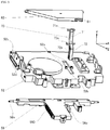
Fig. 1] Fig. 1 is a perspective view in an open state of a head-up display (HUD) apparatus according to an embodiment of the present invention. - [
Fig. 2] Fig. 2 is a partial sectional view in the open state of the HUD apparatus according to the embodiment of the present invention. - [
Fig. 3] Fig. 3 is an exploded view of essential parts of the HUD apparatus according to the embodiment of the present invention. - [
Fig. 4] Fig. 4 is a schematic view for explaining a four-joint link mechanism included in the HUD apparatus according to the embodiment of the present invention. - [
Fig. 5] Fig. 5 is a schematic view for explaining a plate spring according to an embodiment of the present invention. - [
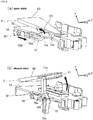
Fig. 6] Fig. 6 is sectional perspective view for explaining an opening or closing operation of a lid of the HUD apparatus according to the embodiment of the present invention, whereinFig. 6 (a) shows an open state andFig. 6 (b) shows a closed state. - [
Fig. 7] Fig. 7 is a partial sectional view of the HUD apparatus according to the embodiment of the present invention, whereinFig. 7 (a) is a view showing a process of transition from the open state to the closed state andFig. 7 (b) is a view showing the closed state. - An HUD apparatus according to an embodiment of the present invention will be described with reference to the drawings.
- An
HUD apparatus 1, as shown inFig. 1 to Fig. 7(a) andFig. 7 (b) , is provided with acasing 10, adisplay 20, acircuit board 30, acombiner 40, astorage mechanism 50, alid 60, alid supporting part 70, and aplate spring 80. Incidentally, thestorage mechanism 50 is an example of storage means, and theplate spring 80 is an example of biasing means. - The
HUD apparatus 1 is arranged on a dashboard of a vehicle, for example, and projects display light L from thedisplay 20 to thecombiner 40 to thereby display an image, which is represented by the display light L, as a virtual image. This image notifies, to a user (mainly, a driver), information such as a cruising vehicle speed pertinent to a vehicle in which the apparatus is mounted or vehicle information which is indicative of route guidance information employing a known car navigation system. Namely, the vehicle information includes various items of information for assisting drive as well as information pertinent to the vehicle owned by the user. - Incidentally, for the sake of a clear understanding of the configuration, as seen from a viewer E (refer to
Fig. 1 ) who visually recognize an image which is displayed by theHUD apparatus 1, the axis along the transverse direction is defined as the X-axis; the axis along the vertical direction is defined as the Y-axis; and the axis that is orthogonal to the X-axis and the Y-axis is defined as the Z-axis, and the constituent elements constituting the HUD apparatus will be described appropriately. In addition, the direction pointed by the arrow that is indicative of each of the X-axis, Y-axis, and Z-axis is defined as the positive (+) direction in each axis and the opposite direction thereto is defined as the negative direction (-). - The
casing 10 is composed of anupper case 11 and alower case 12 which are linked with each other, and internally stores the constituent elements (thedisplay 20 to the lid supporting part 70). (Incidentally, thecombiner 40 is stored while in a storage state which will be described later). In theupper case 11, anexit port 11a and aninsertion port 11b are formed. Theexit port 11a is an opening through which the display light L from thedisplay 20 is routed (emitted) to the outside of thecasing 10. Theinsertion port 11b is an opening which is required to set thecombiner 40 in a protruding state which will be described later. Inside of thelower case 12, thecircuit board 30 and a storage mechanism casing 32 which will be described later are fixed by a predetermined method. - The
display 20 displays an image which is representative of vehicle information to thereby emit the display light L that is representative of the image. Thedisplay 20 is composed of a transmission-type liquid crystal display or a self-emission type display which is composed of a liquid crystal panel and a light source for backlight, for example. Thedisplay 20 is arranged at a predetermined position in thecasing 10 so as to oppose to thecombiner 40 that is in the protruding state. The display light L that has been emitted from thedisplay 20 passes through theexit port 11a and travels to thecombiner 40. - The
circuit board 30 is a printed circuit board on which a control part (not shown) to control entire operation of theHUD apparatus 1 has been implemented. The control part is provided with: a CPU (Central Processing Unit); a storage part which consists of a ROM (Read Only Memory) and a RAM (Random Access Memory) or the like; and a driver to drive a motor 55 (Fig. 2 ) which will be described later. In the storage part, an operation program which is indicative of the CPU processing procedures or image data or the like to be displayed on thedisplay 20 are stored in advance. Thecircuit board 30 is connected by an FPC (Flexible Printed Circuit) or the like to each of thedisplay 20, amotor 55, and position detection means (which will be described later). The control part serves to: (i) cause thedisplay 20 to display an image which is indicative of predetermined vehicle information, based on various items of vehicle information that has been acquired from an ECU (Electronic Control Unit) or the like of the vehicle; (ii) drive themotor 55 in accordance with an operation signal from an operation part which will be described later to move aslider 56 which will be described later); and (iii) determine a position of thecombiner 40, based on a detection signal from a position detection means which will be described later. - The
combiner 40 is composed of a plate-shaped half mirror having a curved surface; and a hologram element or the like. Thecombiner 40 is transited from one state to the other state between: a state in which the combiner has protruded from the casing 10 (hereinafter, referred to as a "protruding state"); and a state in which the combiner has been stored in the casing 10 (hereinafter, referred to as a "stored state"), in accordance with operation of thestorage mechanism 50 which will be described later. - Although later described in detail, when the
combiner 40 is transited from the protruding state to the stored state, thelid 60 that opens or closes theexit port 11a is conjunctively transited from the open state to the closed state as well. This also applies to a transition to the reverse side, similarly. Namely, in theHUD apparatus 1 according to the embodiment, when thecombiner 40 is established in the protruding state, thelid 60 is established in the open state or when thecombiner 40 is established in the stored state, thelid 60 is established in the closed state. Incidentally, the case in which thelid 60 is established in the open state is expressed as theHUD apparatus 1 being in the open state as well. This also applies to the case of the closed state, similarly. - The
combiner 40 that is in the protruding state, as shown inFig. 1 and Fig. 2 , is established in a posture protruding upward from theinsertion port 11b of thecasing 10. Incidentally,Fig. 2 is a partial sectional view in a case where thecasing 10 has been cut on a predetermined plane parallel to the YZ-plane, and is also a view in a case where an internal mechanism of thecasing 10 is seen from the left side face (this also applies toFig. 7 (a) and Fig. 7 (b) , similarly). - The
combiner 40 that is in the protruding state, on aconcave surface 40a (the surface approximately facing the +Z-axis), receives the display light L that has been emitted by thedisplay 20 and then varies an optical path of the display light L that has been incident thereto. Incidentally, in a case where a half mirror is employed as thecombiner 40, the optical path of the display light L is varied by means of reflection or in a case where a hologram element is employed, the optical path of the display light L is varied by means of diffraction. Theconcave surface 40a of thecombiner 40 is configured as a concave surface which has a function of focusing the display light L, and which is capable of forming a virtual image at a front distal side more significantly than the case in which the light is simply reflected (for example, about 1 m front side more significantly than the combiner 40). Thecombiner 40 forms a virtual image of the image indicated by the display light L at the front position F (Fig. 1 ) and causes the light from the front side to pass through. In this manner, theHUD apparatus 1 is capable of causing the viewer E to visually recognize the image that has been displayed as the virtual image while being overlapped on a real landscape. - The
storage mechanism 50 shown inFig. 3 is a mechanism to transit thecombiner 40 from one state to the other state between the protruding state and the stored state. Thestorage mechanism 50 is provided with aholder 51, astorage mechanism casing 52, a first connectingpart 53; a second connectingpart 54, amotor 55, and aslider 56. - The
holder 51 is for holding thecombiner 40. Theholder 51 is a columnar member extending in the X-direction, and is formed of a resin material, for example. Thecombiner 40 is held with one end part thereof (a lower end part in the protruding state) being fixed to theholder 51. - The
storage mechanism casing 52 is fixed to the inside of thecasing 10, and is immobilized with respect to thecasing 10. Thestorage mechanism casing 52 is formed of a resin material, for example, and as shown inFig. 3 , has: a supportingpart 52a to rotatably support thelid supporting part 70; anopening 52b which is provided so as not to block a rotation movement of thelid supporting part 70; and aside part 52c having a plane which is substantially parallel to the YZ plane. The first connectingpart 53 and the second connectingpart 54 are mounted to theside part 52c. In addition, afirst contact part 56a (which will be described later) of theslider 56 is inserted into theside part 52c, and ahole 52d to expose thefirst contact part 56a to the outside of thestorage mechanism casing 52 is formed. Thehole 52d is formed so as to approximately extend in the Z-direction in association with a movement range of theslider 56. In addition, themotor 55 is arranged at a predetermined position of thestorage mechanism casing 52. - The first connecting
part 53 is a rod-shaped member which is rotatably provided in thestorage mechanism casing 52 and which links thestorage mechanism casing 52 and theholder 51 with each other, and is formed of a resin material, for example. The first connectingpart 53, at one end part thereof, is mounted to theside part 52c of thestorage mechanism casing 52 so as to be rotatable about a shaft P parallel to the X-axis. In addition, the first connectingpart 52, at the other end part thereof, supports theholder 51 to be rotatable about a shaft Q parallel to the X-axis. For example, at theside part 52a, a convex part along the shaft P is formed, and at one end part of the first connectingpart 53, a concave part to engage with the convex part is formed, and the first connectingpart 53 is thereby made rotatable about the shaft P. In addition, at theholder 51, a convex part along the shaft Q is formed, and at the other end part of the first connectingpart 53, a concave part which engages with the convex part is formed, and theholder 51 is thereby made rotatable with respect to the first connectingpart 53 about the shaft Q. A relationship between these concave and convex parts may be reversal from each other. Incidentally, in respect of each member which is made rotatable about a respective one of axes S, R, T, and U which will be described later as well, a relationship between a mounting side and a mounted side is established similarly; and therefore, a description of how each member is rotatably mounted is omitted here. In the light of the foregoing descriptive matters, it is possible to say that the first connectingpart 53 is linked with thestorage mechanism casing 52 by joints around the shaft P. In addition, in respect of the axes Q, R, and S about the respective joints of the four-joint link mechanism which will be described later as well, the joints to link the respective members with each other are configured similarly, and the joints present about the respective shafts has one degree of freedom. Incidentally, inFig. 2 ,Fig. 4 ,Fig. 7 (a) and Fig. 7 (b) , the shafts P, S, T, and U that were immobilized with respect to thecasing 10 were represented by the filled circle, and the shafts Q and R to move with respect to thecasing 10 were represented by the contour circle. - The second connecting
part 54 is a member which is rotatably provided in thestorage mechanism casing 52 and which links thestorage mechanism casing 52 and theholder 51 with each other, and is formed of a resin material, for example. The second connectingpart 54 is provided so as to be paired with the first connectingpart 53, and is located at a lower side more significantly than the first connectingpart 53 that is in the protruding state of thecombiner 40. The second connectingpart 54, at one end part thereof, is mounted to theside part 52c of thestorage mechanism casing 52 so as to be rotatable about the shaft S parallel to the X-axis. In addition, the second connectingpart 54, at the other end part thereof, supports theholder 51 to be rotatable about the shaft R parallel to the X-axis. - The
storage mechanism 50 moves thecombiner 40 by the four-joint link mechanism to transit the combiner from one state to the other state between the protruding state and the stored state. The four-joint link mechanism is known as a mechanism which consists of: a driving joint (a driving link) which communicates with a fixed joint (a fixed link) and one of the joints that are positioned at both ends of the fixed joint, to which a driving force is to be imparted; and an intermediate joint (an intermediate link) which communicates with a driven joint (a driven link) opposing to the driving joint, and which connects the driving joint and the driven joint to each other. In association with this configuration, the four-joint link mechanism included in thestorage mechanism 50 is configured so that: a part of the storage mechanism casing 52 (specifically, a joint connecting the respective centers of the shaft P and the shaft Q to each other) function as a fixed joint; either one of the first connectingpart 53 and the second connectingpart 54 functions as a driving joint to which a driving force is to be imparted by theslider 56; the other one functions as a driven joint; and theholder 51 functions as an intermediate joint (refer toFig. 4 ). In the four-joint link mechanism thus configured, when the combiner is transited from the stored state to the protruding state, the first connecting 52 functions as a driving force to which a driving force is to be imparted by theslider 56, and the second connectingpart 54 functions as a driven joint. In addition, when thecombiner 40 is transited from the protruding state to the stored state, the second connectingpart 54 functions as a driving joint to which a driving force is to be imparted by theslider 56 and the first connectingpart 53 functions as a driven joint. A specific operation will be described later. - Hereinabove, mainly referring to
Fig. 2 , the four-joint link mechanism in a case where the internal mechanism of theHUD apparatus 1 is seen from a right side face was described; and however, theHUD apparatus 1 is configured to be approximately transversely symmetrical, and at the right side thereof, a four-joint link mechanism having a first connecting part and a second connecting part or the like is configured similarly as well. Namely, theHUD apparatus 1 moves thecombiner 40 by the four-joint link mechanism that operates similarly at each of the left and right sides. Thus, a detailed description of the four-joint link mechanism at the right side is omitted here. - The
motor 55 shown inFig. 2 imparts, to theslider 56, a driving force for moving in the longitudinal direction. Themotor 55 rotates a driving shaft under the control of the control part. A gear is pressed in the driving shaft of themotor 55. This gear indirectly meshes with a gear 560 (Fig. 3 ) which is formed at theslider 56. Thegear 560 is formed in the shape of a helical gear which is approximately taken along the Z-direction. With such a configuration, a rotation driving force of themotor 55 is transmitted to theslider 56, and theslider 56 moves in the longitudinal direction. - Incidentally, at a predetermined portion of the
storage mechanism casing 52, position detection means (not shown) is arranged to thereby able to detect whether thecombiner 40 is established in the protruding state or the stored state. The position detection means is composed of: a linear potentiometer to detect a position in the longitudinal direction of theslider 56; and a rotary potentiometer to detect a rotation angle at the periphery of the shaft P of the first connectingpart 53 or the shaft S of the second connectingpart 54 or the like. The position detection means supplies, to the control part, a detection signal which is indicative of position information in a case where theslider 56 is located at a predetermined position. The control part determines, based on this detection signal, whether thecombiner 40 is established in the protruding state or the stored state. - The
slider 56 is provided to be slidable with respect to thestorage mechanism casing 52, and is moved in the longitudinal direction by the driving force of themotor 55. Theslider 56 has: afirst contact part 56a which is brought into contact with the first connectingpart 53 or the second connectingpart 54 according to its movement; and asecond contact part 56b (an example of sliding part) which is brought into contact with the lid supporting part 70). - The
first contact part 56a is a portion which protrudes to the outside of thestorage mechanism casing 52 through ahole 52d of thestorage mechanism casing 52. A tip end of thefirst contact part 56a is located between the first connectingpart 53 and the second connectingpart 54. Thefirst contact part 56a is formed in a columnar shape having a height in the X-axis direction, and is formed of a slidable resin such as polyacetal (POM (Polyoxymethylene)) resin. - The
first contact part 56a, at a tip end thereof, presses and moves the first connectingpart 53 or the second connectingpart 54 to thereby drive the four-joint link mechanism. Namely, by thefirst contact part 56a, a driving force is imparted to the four-joint link mechanism. Specifically, when thefirst contact part 56a presses the first connectingpart 53 forward owing to a forward movement of theslider 56, the pressed first connectingpart 53 rotates clockwise about the shaft P (hereinafter, referred to as "CW (Clock Wise) rotation"), and in accordance with this rotation, the second connectingpart 54 rotates clockwise about the shaft S as well. Namely, in a case where theslider 56 moves forward, the first connectingpart 53 functions as a driving joint and the second connectingpart 54 functions as a driven joint. The four-joint link mechanism that operates in this manner moves thecombiner 40 in the projecting direction. On the other hand, when thefirst contact part 56a presses the second connectingpart 54 backward owing to a backward movement of theslider 56, the pressed second connectingpart 54 rotates counterclockwise about the shaft S (hereinafter, referred to as "CCW (Counter Clock Wise) rotation"), and in accordance with this rotation, the first connectingpart 53 rotates clockwise about the shaft P as well. Namely, in a case where theslider 56 moves backward, the second connectingpart 54 functions as a driving joint and the first connectingpart 53 functions as a driven joint. The four-joint link mechanism that operates in this manner moves thecombiner 40 in the stored direction. Incidentally, the terms "CW rotation" and "CCW rotation" used herein respectively denote the rotation directions in a case where theHUD apparatus 1 is seen from the left side. For the sake of a clear understanding of explanation, this also applies to the following description, similarly. - The
second contact part 56b, as shown in the exploded view ofFig. 3 , is located at a lower side of theopening 52b of thestorage mechanism casing 52. Thesecond contact part 56b gets into a guidingpart 72a (which will be described later) of thelid supporting part 70. Thesecond contact part 56b is formed in a columnar shape having a height in the X-axis direction, and is formed of a sliding resin such as a PM resin. Thesecond contact part 56b slides inside of the guidingpart 72a in conjunction with movement of theslider 56 to thereby rotate thelid supporting part 70. Thelid 60 opens or closes according to the rotation movement of thelid supporting part 70. A detailed description of operation will be given later. - The
lid 60 releases theexit port 11a in the open state and covers theexit port 11a in the closed state. As described later, thelid 60 moves together with thecombiner 40 and is established in the open state when thecombiner 40 is established in the protruding state or is established in the closed state when thecombiner 40 is established in the stored state. In this manner, when theHUD apparatus 1 is not in use, it is possible to prevent the entry of dust or the like to the inside. - The
lid 60 is mounted to an opening end of the upper case 11 (thecombiner 40 side) so as to be rotatable about the shaft Y parallel to the X-axis. Also, aslider 71a (which will be described later) of thelid supporting part 70 is engaged with thelid 60, and a slidingpassage 61 is provided to slide theslider 71a according to the rotation of thelid supporting part 70 and then vary a supporting position of thelid 60. The slidingpassage 61, as shown inFig. 6 (a) and Fig. 6 (b) , is a groove-shaped portion formed along the direction in which thelid 60 extends. - The
lid supporting part 70 is a rod-shaped member, and supports thelid 60. Thelid supporting part 70 has ashaft part 70a which is rotatably supported by the supportingpart 52a of thestorage mechanism casing 52 so as to be thereby rotatable about the shaft U parallel to the X-axis with respect to thestorage mechanism casing 52. Thelid supporting part 70 supports thelid 60 at thefirst portion 71 that is upper than theshaft part 70a. Also, asecond portion 72 which is lower than theshaft part 70a of thelid supporting part 70 passes through theopening 52b of thestorage mechanism casing 52, and is located at a lower side. - At a tip end of the
first portion 71, acolumnar slider 71a protruding to the left and right is formed. Theslider 71a is slidably engaged with the slidingpassage 61 of thelid 60. - The
second contact part 56b of theslider 56 is slidably engaged with thesecond portion 72, and the guidingpart 72a to gradually vary the opening or closing speed of thelid 60 is formed. - The guiding
part 72a, in a side view as shown inFig. 2 , is formed in a U-shape, one end of which is an open end and which is folded in the middle leading from one end to the other end. At the time of assembling, thesecond contact part 56b of theslider 56 is inserted into the guidingpart 72a from the open end. The guidingpart 72a is formed as a groove which is depressed in the X-direction or as a hole which penetrates thesecond portion 72 in the X-direction. As shown inFig. 2 andFig. 6(a) , thesecond contact part 56b is slidably inserted so as to be sandwiched by the guidingpart 72a. The guidingpart 72a has: a parallel part extending in parallel to the movement direction of theslider 56 backward from the open end side in the protruding state of thecombiner 40 shown inFig. 2 ; and an inclined part to incline from the parallel part towards the shaft U. In addition, at the inclined part, a curved surface to gradually vary the opening or closing speed of the lid 60 (the curved shape in the side view ofFig. 2 ) is formed. A description will be given later with respect to how this curved surface gradually varies the opening or closing speed of thelid 60. - The
plate spring 80 is formed of a metal, for example, and is formed to be foldable. Theplate spring 80, as shown inFig. 2 , is provided so that a folded portion is located at a lower side of the shaft T that is a rotation center of thelid 60, one side of which is fixed to theupper case 11 with the folded portion being sandwiched, and the other side of which is fixed to thelid 60 as well. Here, as shown inFig. 5 , a folding angle of theplate spring 80 is substantially half (including just half) of an opening or closing angle of thelid 60. For example, as shown in the figure, in a case where the opening or closing angle of thelid 60 is set to 20 degrees, the folding angle of theplate spring 80 is obtained as 10 degrees. The thus foldedplate spring 80 biases thelid 60 that is in the open state, along the direction approaching towards the closed state, whereas the spring biases thelid 60 that is in the closed state, along the direction approaching towards the open state. In this manner, it is possible to prevent a backlash at the time of opening or closing of thelid 60 owing to elasticity of theplate spring 80, and it is also possible to assist startup of themotor 55. - Hereinabove, a structure of the
HUD apparatus 1 has been described so far. Next, a transition of thecombiner 40 in theHUD apparatus 1 and the opening or closing operation of thelid 60 will be described. - For example, at a predetermined part of the
HUD apparatus 1 or on a dashboard of a vehicle, an operation part which consists of a button or the like is provided, and when the user (usually, the viewer E) depressed this button, an operation signal which is indicative of the contents of operation is supplied to the control part. The control part that has responded to the operating signal drives themotor 55 to thereby move thecombiner 40 via theslider 56. Specifically, the control part rotates a driving shaft of themotor 55 at a constant speed and in the rotation direction according to the operation signal. The rotation driving force of themotor 55 is transmitted to theslider 56 via a plurality of gears and then theslider 56 moves in the longitudinal direction. - First of all, a description will be given with respect to a case in which the
HUD apparatus 1 is transited from the open state shown inFig. 2 (the protruding state of the combiner 40) to the closed state shown inFig. 7 (b) (the stored state of the combiner 40). In this case, theslider 56 moves backward. Incidentally, inFig. 7(c) and Fig. 7 (b) , theplate spring 80 is omitted here. - When the
first contact part 56a presses the second connectingpart 54 backward owing to the backward movement of theslider 56, the pressed second connectingpart 54 rotates CCW about the shaft S, and in accordance with this rotation, the first connectingpart 53 rotates CCW about the shaft P as well. In this manner, as shown inFig. 7 (a) , the four-joint link operates, and thecombiner 40 moves to a lower side so as to be pulled up to the inside through theinsertion port 11b of thecasing 10. At this juncture, theholder 51 to hold thecombiner 40 functions as an intermediate joint to connect the shaft Q and the shaft R to each other; and therefore, thecombiner 40 moves to a lower side while rotating CCW in accordance with the rotation operations of the first connectingpart 53 and the second connectingpart 54. When thecombiner 40 moves in this way and then is transited until the stored state shown inFig. 7(b) is stablished, the detection signal indicative of the fact that thecombiner 40 has transited in the stored state, from the position detection means, is supplied to the control part. The control part that has responded to this detection signal stops the operation of themotor 55. In this manner, the transition from the protruding state (Fig. 2 ) to the stored state (Fig. 7 (b) of thecombiner 40 completes. - The
HUD apparatus 1 according to the embodiment is characterized in that thelid 60 is transited from the open state to the closed state in conjunction with the transition from protruding state to the stored state of thecombiner 40. Hereinafter, the transition of thelid 60 will be described. - In conjunction with the backward movement of the
slider 56, as shown inFig. 6 (a) , thesecond contact part 56b slides the guidingpart 72a of thelid supporting part 70 backward. While thesecond contact part 56b slides the parallel part of the guidingpart 72a, thelid supporting part 70 does not start rotation about the shaft U. - In conjunction with the backward movement of the
slider 56, as shown inFig. 7 (a) , thecombiner 40 moves backward, and in that course, thesecond contact part 56b is guided to the inclined part from the parallel part of the guidingpart 72a towards the shaft U. When thesecond contact part 56b starts sliding at the inclined part, the inclined part inclines with respect to the movement direction of theslider 56 and then thelid supporting part 70 starts the CCW rotation about the shaft U. In accordance with this rotation, theslider 71a of thelid supporting part 70 moves towards the shaft T side the slidingpassage 61 that has been formed at thelid 60 and then varies the position for supporting thelid 60 so as not to block rotation of the lid supporting part 70 (refer toFig. 6 (a) and Fig. 6 (b) ). - In accordance with the variation between the CCW rotation of the
lid supporting part 70 and the supporting position of thelid 60 by theslider 71a, thelid 60 rotates CCW about the shaft T and rises and then is transited from the closed state towards the open state. - When the
second contact part 56b starts sliding on the curved surface that has been formed at the shaft U side of the inclined part, the rotation speed of thelid supporting part 70 gradually lowers. This curved surface is formed at a curvature to an extent such that action of thesecond contact part 56 with respect to the lid supporting part 70 (the action in the circumferential direction about the shaft U) gradually weakens. In addition, when thesecond contact part 56b is located at a terminal end part of the guidingpart 72a, thelid 60 is established in the closed state shown inFig. 6 (b) andFig. 7 (b) . - The curved surface has been thus formed at the guiding
part 72a of thelid supporting part 70; and therefore, it is possible to ensure the rotation speed of thelid 60 becomes gentle immediately before thelid 60 is established in the closed state. - On the other hand, when the
combiner 40 is transited from the stored state to the protruding state, theHUD apparatus 1 makes operation by reversing the operating procedures as described previously. In a brief description, the first connectingpart 53 is pressed forward against thefirst contact part 56a due to the forward movement of theslider 56, and the four-joint link mechanism thereby operates and then thecombiner 40 is transited from the stored state to the protruding state. In this course, thesecond contact part 56b slides the guidingpart 72a of thelid supporting part 70 from the inclined part towards the parallel part. Thelid 60 is established in the open state with a timing of thesecond contact part 56b having arrived at the parallel part from the inclined part. Incidentally, by the curved surface described previously that has been formed at the inclined part, thelid 60 gently rotates CW immediately after the start of the closing operation. Namely, the rotation speed of thelid 60 becomes gentle immediately before thelid 60 is established in the closed state and immediately after the operation from the closed state to the open state has started. In this manner, it is possible to produce a feeling of luxury of theHUD apparatus 1 and increase the value of the product. - In addition, the
lid 60 established in the open state is biased along the direction approaching towards the closed state by theplate spring 80 as described previously, whereas thelid 60 established in the closed state is biased along the direction approaching towards the open state. Thus, it is possible to assist startup of themotor 55 when starting the transition of thelid 60 from one state to the other state between the open state and the closed state. - Incidentally, the timing with which the
lid 60 is established in the closed state does not need to be the same as the timing with which the transition to the storage state of thecombiner 50 has completed. Similarly, the timing with which thelid 60 is established in the open state does not need to be the same as the timing with which the transition to the protruding state of thecombiner 40 has completed. It is sufficient if thelid 60 is established in the open state or closed state with an arbitrary timing in the course in which thecombiner 40 moves. - The
HUD apparatus 1 that consists of the constituent elements described above is provided with: thedisplay 20 to emit display light L which is representative of a picture (an image); thecasing 10 to store thedisplay 20 therein, having theexit port 11a to emit the display light L from thedisplay 20 to the outside; thecombiner 40 to receive the display light L that has been emitted from theexit port 11a and then display a virtual image of the picture; a storage mechanism 50 (an example of storage means) having theslider 56 which moves inside of thecasing 10, for transiting thecombiner 40 from one state to the other state between the protruding state and the stored state by the four-joint link mechanism that operates in conjunction with movement of theslider 56; alid 60 to release theexit port 11a in the open state or cover theexit port 11a in the closed state; and thelid supporting part 70 which is provided to be rotatable with respect to thecasing 10, thelid supporting part 70 supporting thelid 60 at afirst portion 71, in which asecond portion 72 located so as to be opposite to thefirst portion 71 with a rotation center being sandwiched is brought into contact with theslider 56. When theslider 56 moves in a predetermined direction, thecombiner 40 is transited from the protruding state to the stored state, and in accordance with the rotation of thelid supporting part 70, thelid 60 is transited from the open state to the closed state, or alternatively, when theslider 56 moves in the opposite direction to the predetermined direction, thecombiner 40 is transited from the stored state to the protruding state, and in accordance with the rotation of thelid supporting part 70, thelid 60 is transited from the closed state to the open state. Specifically, thestorage mechanism 50 has: the holder 51 (an example of holding part) to hold the combiner; and a pair of the first connectingpart 53 and the second connectingpart 54 to connect thecasing 10 and theholder 51 to each other, which are provided to be rotatable with respect to thecasing 10; and the four-joint link mechanism is characterized in that one of the first connectingpart 53 and the second connectingpart 54 is configured as a driving mechanism to which a driving force is to be imparted by theslider 56, the other one is configured as a driven joint, theholder 51 is configured as an intermediate joint, a joint to connect the respective rotation centers (shaft P and shaft S) of the first connectingpart 53 and the second connectingpart 54 to each other is configured as a fixed joint. In this manner, theHUD apparatus 1 was configured to be able to open or close thelid 60 in conjunction with the movement of thecombiner 40; and therefore, there is no need to provide an actuator exclusively used for the opening or closing operation of thelid 60 and a simple configuration is accomplished. In addition, when theHUD apparatus 1 is not in use, theexit port 11a is covered (closed); and therefore, it is possible to prevent entry of dust or the like to the inside. - In addition, the
HUD apparatus 1 is further provided with a plate spring 80 (an example of biasing means) to bias thelid 60 established in the open state, along the direction approaching towards the closed state, and to bias thelid 60 established in the closed state, along the direction approaching towards the open state. Specifically, theplate spring 80 is formed to be foldable, one portion of which is fixed to thecasing 10 with a folded portion being sandwiched, and the other portion of which is fixed to thelid 10. In this manner, as described previously, it is possible to prevent a backlash at the time of opening or closing of thelid 60 and to assist startup of themotor 55. - Further, the
slider 56 has thesecond contact part 56b (an example of sliding part) to slide thesecond portion 72 of thelid supporting part 70, and at thesecond portion 72, the guidingpart 72a to guide and slide asecond contact part 56b, having a curved surface to gradually vary the opening or closing speed of thelid 60, is formed. In this manner, as described previously, it is possible to reduce the rotation speed of thelid 60 immediately before thelid 60 is established in the closed state and immediately after the operation from the closed state to the open state has been started, and it is also possible to increase the value of the product. - Incidentally, the present invention is limited by the embodiment and drawings. Of course, modifications (including deletion of constituent element(s) can be applied to the embodiment and drawings.
- Although the foregoing description showed an example of a configuration in which the
first contact part 56a of theslider 56 is located between the first connectingpart 53 and the second connectingpart 54 to drive the four-joint link mechanism, the present invention is not limitative thereto. What is provided instead thereof may be a configuration in which thefirst contact part 56a presses either one of the first connectingpart 53 and the second connectingpart 54 in a predetermined direction, and an elastic member to bias the first connectingpart 53 or the second connectingpart 54 is provided in an opposite direction to the predetermined direction. In addition, although the foregoing description shows an example in which thecombiner 40 is moved by the four-joint link mechanism that operates in conjunction with the movement of theslider 56, the link mechanism may be composed of a three-joint or less link or a five-joint more link. - Although in the foregoing description, the
plate spring 80 was employed as an example in which means for biasing thelid 60 established in the open state, along the direction approaching towards the closed state, and biasing thelid 60 established in the closed state, along the direction approaching towards the open state, the present invention is not limitative thereto. Such biasing means may be implemented by employing another elastic member such as a torsion spring, a resin spring, or a rubber solely or using a plurality of elastic members in combination. - Although the foregoing description showed an example of a layout in which the
display 20 and thecombiner 40 oppose to each other, the present invention is not limitative thereto. For example, it may be that thedisplay 20 is disposed so as to emit the display light L to the +Z-axis direction side, for example, an optical path is returned by a predetermined reflecting member, and the display light L is caused to arrive at thecombiner 40. - Although the foregoing description showed an example of employing the
motor 55 that is constant in terms of the rotation speed of the driving shaft, the present invention is not limitative thereto. A servomotor or a stepping motor may be employed instead thereof. If the rotation angle of the driving shaft is controlled by these motors, it is possible to adjust the opening or closing speed of thelid 60, without a need to provide a curved surface that varies the opening or closing speed of thelid 60, at the guidingpart 72a of thelid supporting part 70. However, in a case where there is a desire to simplify control, it is preferable to provide a curved surface. - Although the foregoing description showed a vehicle as an example of a transportation vehicle in which the
HUD apparatus 1 is installed, the present invention is not limitative thereto. It may be that theHUD apparatus 1 is installed in the vicinity of a navigation seat in a ship, a cockpit in an aircraft or a driver's seat in any other transportation vehicle. - In the foregoing description, a description of publicly known technical matters which are not so essential was appropriately omitted for the sake of a clear understanding of the present invention.
- The present invention is preferably suitable for a head-up display apparatus to be mounted on a vehicle.
-
- 1
- Head-up display (HUD) apparatus
- 10
- Casing
- 11a
- Exit port
- 11b
- Insertion port
- 20
- Display
- L
- Display light
- 30
- Circuit board
- 40
- Combiner
- 50
- Storage mechanism
- 51
- Holder
- 52
- Storage mechanism casing
- 53
- First connecting part
- 54
- Second connecting part
- P, Q, R, S
- Shafts
- 55
- Motor
- 56
- Slider
- 56a
- First contact part
- 56b
- Second contact part
- 60
- Lid
- 61
- Sliding passage
- 70
- Lid supporting part
- 71
- First portion
- 71a
- Slider
- 72
- Second portion
- 72a
- Guiding part
- 80
- Plate spring
Claims (5)
- A head-up display apparatus comprising:a display to emit display light which is representative of a picture and then emit the display light from the display outside;a casing to store the display inside, having a casing to emit the display from the display outside;a combiner to receive the display light that has been emitted from the exit port and then display a virtual image of the picture;storage means having a slider to move inside of the casing, for transiting the combiner from one state to another state between a protruding state in which the casing has protruded from the casing and a stored state in which the combiner has been stored in the casing, by a link mechanism which operates in conjunction with movement of the slider;a lid to release the exit port in an open state or cover the exit port in a closed state; anda lid supporting part which is provided to be rotatable with respect to the casing, the lid supporting part supporting the lid at a first portion, in which a second portion located so as to be opposite to the first portion with a rotation center being sandwiched is brought into contact with the slider,wherein, when the slider moves in a predetermined direction, the combiner is transited from the protruding state to the stored state, and the lid is transited from the open state to the closed state in accordance with rotation of the lid supporting part, andwherein, when the slider moves in an opposite direction to the predetermined direction, the combiner is transited from the stored state to the protruding state, and the lid is transited from the closed state to the open state in accordance with the rotation of the lid supporting part.
- The head-up display apparatus according to claim 1, wherein
the storage means has: a holding part for holding the combiner; and a pair of a first connecting part and a second connecting part to connect the casing and the holding part to each other, and
the link mechanism is a four-joint link mechanism in which one of the first connecting part and the second connecting part is configured as a driving joint to which a driving force is to be imparted by the slider, another one is configured as a driven point, the holding part is configured as an intermediate joint, and a joint to connect respective rotation centers of the first connecting part and the second connecting part to each other is configured as a fixed joint. - The head-up display apparatus according to claim 1 or claim 2, further comprising biasing means for biasing the lid established in the open state, along a direction approaching towards the closed state, and biasing the lid established in the closed state, along a direction approaching towards the open state.
- The head-up display apparatus according to claim 3, wherein
the biasing means is a plate spring which is formed to be foldable, a portion of which is fixed to the casing with a folded portion being sandwiched, and another portion of which is fixed to the lid. - The head-up display apparatus according to any one of claims 1 to 4, wherein the slider has a sliding part to slide the second portion of the lid supporting part, and
at the second portion, a guiding part to guide and slide the sliding part, having a curved surface which graduallyvaries an opening or closing speed of the lid, is formed.
Applications Claiming Priority (2)
| Application Number | Priority Date | Filing Date | Title |
|---|---|---|---|
| JP2014213783A JP6524637B2 (en) | 2014-10-20 | 2014-10-20 | Head-up display device |
| PCT/JP2015/079326 WO2016063807A1 (en) | 2014-10-20 | 2015-10-16 | Head-up display apparatus |
Publications (2)
| Publication Number | Publication Date |
|---|---|
| EP3210812A1 true EP3210812A1 (en) | 2017-08-30 |
| EP3210812A4 EP3210812A4 (en) | 2018-07-18 |
Family
ID=55760844
Family Applications (1)
| Application Number | Title | Priority Date | Filing Date |
|---|---|---|---|
| EP15853174.9A Withdrawn EP3210812A4 (en) | 2014-10-20 | 2015-10-16 | Head-up display apparatus |
Country Status (3)
| Country | Link |
|---|---|
| EP (1) | EP3210812A4 (en) |
| JP (1) | JP6524637B2 (en) |
| WO (1) | WO2016063807A1 (en) |
Cited By (1)
| Publication number | Priority date | Publication date | Assignee | Title |
|---|---|---|---|---|
| CZ308671B6 (en) * | 2019-11-20 | 2021-02-03 | Brano A.S. | Car body cover control mechanism |
Families Citing this family (3)
| Publication number | Priority date | Publication date | Assignee | Title |
|---|---|---|---|---|
| JP6227061B1 (en) * | 2016-06-22 | 2017-11-08 | ミネベアミツミ株式会社 | Display device |
| CN111367080B (en) * | 2016-12-01 | 2021-08-03 | 腾讯科技(深圳)有限公司 | Wearable device |
| KR102577359B1 (en) * | 2018-04-17 | 2023-09-13 | 현대모비스 주식회사 | Head up display appratus for vehicle |
Family Cites Families (9)
| Publication number | Priority date | Publication date | Assignee | Title |
|---|---|---|---|---|
| US4664475A (en) * | 1985-08-14 | 1987-05-12 | Hughes Aircraft Company | Combiner mounting and stowage mechanism |
| JPH1191403A (en) * | 1997-09-25 | 1999-04-06 | Asahi Glass Co Ltd | Head-up display |
| DE102005052031B4 (en) * | 2005-10-31 | 2015-03-12 | Robert Bosch Gmbh | Foldable display device with cover, in particular for motor vehicles |
| JP5923251B2 (en) * | 2011-06-08 | 2016-05-24 | 日本精機株式会社 | Head-up display device |
| JP5702231B2 (en) * | 2011-06-08 | 2015-04-15 | 株式会社ニフコ | Lid link structure |
| JP5958328B2 (en) * | 2012-12-27 | 2016-07-27 | 日本精機株式会社 | Combiner storage device, head-up display device |
| US9188781B2 (en) * | 2012-03-29 | 2015-11-17 | Nippon Seiki Co., Ltd. | Combiner storage device, head-up display device |
| JP5880212B2 (en) * | 2012-03-29 | 2016-03-08 | 日本精機株式会社 | Combiner storage device, head-up display device |
| JP5917257B2 (en) * | 2012-04-19 | 2016-05-11 | 矢崎総業株式会社 | Head-up display device |
-
2014
- 2014-10-20 JP JP2014213783A patent/JP6524637B2/en not_active Expired - Fee Related
-
2015
- 2015-10-16 EP EP15853174.9A patent/EP3210812A4/en not_active Withdrawn
- 2015-10-16 WO PCT/JP2015/079326 patent/WO2016063807A1/en not_active Ceased
Cited By (1)
| Publication number | Priority date | Publication date | Assignee | Title |
|---|---|---|---|---|
| CZ308671B6 (en) * | 2019-11-20 | 2021-02-03 | Brano A.S. | Car body cover control mechanism |
Also Published As
| Publication number | Publication date |
|---|---|
| JP2016078732A (en) | 2016-05-16 |
| JP6524637B2 (en) | 2019-06-05 |
| WO2016063807A1 (en) | 2016-04-28 |
| EP3210812A4 (en) | 2018-07-18 |
Similar Documents
| Publication | Publication Date | Title |
|---|---|---|
| CN104245426B (en) | Combiner holding device, head-up display | |
| JP6265701B2 (en) | Head-up display device | |
| CN102582525B (en) | Dual Mirror Positioning System for Head-Up Displays | |
| US9989761B2 (en) | Tilting mechanism and display device provided with the same | |
| US9063329B2 (en) | Head up display device and method for vehicle | |
| JP5997489B2 (en) | Vehicle display device | |
| EP2703206B1 (en) | In-vehicle display apparatus | |
| EP3208649A1 (en) | Head-up display apparatus | |
| JP6045064B2 (en) | Vehicle display device | |
| US10416449B2 (en) | Display apparatus having moving mechanism | |
| EP3203302A1 (en) | Head-up display apparatus | |
| JP6524637B2 (en) | Head-up display device | |
| EP2851233B1 (en) | Head-up display device | |
| US7466220B2 (en) | Head-up display apparatus and mirror unit for the same | |
| JP5880212B2 (en) | Combiner storage device, head-up display device | |
| JP6061525B2 (en) | Vehicle display device | |
| US20180180142A1 (en) | Display apparatus | |
| JP6449701B2 (en) | Head-up display device | |
| JP5958328B2 (en) | Combiner storage device, head-up display device | |
| JP3718972B2 (en) | Open / close type reflective display | |
| JP2019131185A (en) | Head-up display device | |
| JPH08156710A (en) | On-vehicle display device | |
| JP2006143109A (en) | On-vehicle movable display device | |
| JP2017097329A (en) | Head-up display device | |
| JP2016124505A (en) | Head-up display device |
Legal Events
| Date | Code | Title | Description |
|---|---|---|---|
| PUAI | Public reference made under article 153(3) epc to a published international application that has entered the european phase |
Free format text: ORIGINAL CODE: 0009012 |
|
| 17P | Request for examination filed |
Effective date: 20170505 |
|
| AK | Designated contracting states |
Kind code of ref document: A1 Designated state(s): AL AT BE BG CH CY CZ DE DK EE ES FI FR GB GR HR HU IE IS IT LI LT LU LV MC MK MT NL NO PL PT RO RS SE SI SK SM TR |
|
| AX | Request for extension of the european patent |
Extension state: BA ME |
|
| DAV | Request for validation of the european patent (deleted) | ||
| DAX | Request for extension of the european patent (deleted) | ||
| RIC1 | Information provided on ipc code assigned before grant |
Ipc: B60K 35/00 20060101AFI20180605BHEP Ipc: G02B 27/01 20060101ALI20180605BHEP |
|
| A4 | Supplementary search report drawn up and despatched |
Effective date: 20180614 |
|
| GRAP | Despatch of communication of intention to grant a patent |
Free format text: ORIGINAL CODE: EPIDOSNIGR1 |
|
| INTG | Intention to grant announced |
Effective date: 20190729 |
|
| STAA | Information on the status of an ep patent application or granted ep patent |
Free format text: STATUS: THE APPLICATION IS DEEMED TO BE WITHDRAWN |
|
| 18D | Application deemed to be withdrawn |
Effective date: 20191210 |