EP3210805A1 - Vehicle air-conditioning apparatus - Google Patents
Vehicle air-conditioning apparatus Download PDFInfo
- Publication number
- EP3210805A1 EP3210805A1 EP17155117.9A EP17155117A EP3210805A1 EP 3210805 A1 EP3210805 A1 EP 3210805A1 EP 17155117 A EP17155117 A EP 17155117A EP 3210805 A1 EP3210805 A1 EP 3210805A1
- Authority
- EP
- European Patent Office
- Prior art keywords
- communicating
- communicating portion
- sealing member
- conditioning apparatus
- water
- Prior art date
- Legal status (The legal status is an assumption and is not a legal conclusion. Google has not performed a legal analysis and makes no representation as to the accuracy of the status listed.)
- Granted
Links
Images




Classifications
-
- B—PERFORMING OPERATIONS; TRANSPORTING
- B60—VEHICLES IN GENERAL
- B60H—ARRANGEMENTS OF HEATING, COOLING, VENTILATING OR OTHER AIR-TREATING DEVICES SPECIALLY ADAPTED FOR PASSENGER OR GOODS SPACES OF VEHICLES
- B60H1/00—Heating, cooling or ventilating devices
- B60H1/00507—Details, e.g. mounting arrangements, desaeration devices
- B60H1/00514—Details of air conditioning housings
- B60H1/00528—Connections between housing parts
-
- B—PERFORMING OPERATIONS; TRANSPORTING
- B60—VEHICLES IN GENERAL
- B60H—ARRANGEMENTS OF HEATING, COOLING, VENTILATING OR OTHER AIR-TREATING DEVICES SPECIALLY ADAPTED FOR PASSENGER OR GOODS SPACES OF VEHICLES
- B60H1/00—Heating, cooling or ventilating devices
- B60H1/00507—Details, e.g. mounting arrangements, desaeration devices
- B60H2001/00635—Air-tight sealing devices
Definitions
- the present invention relates to an air-conditioning apparatus that is to be mounted on a vehicle.
- a vehicle air-conditioning apparatus is configured to flow air into an internal space of a unit case, condition the temperature thereof, then blow out the conditioned air into a vehicle cabin, and in some cases, sucks rainwater, mist, snow, and the like existing outside the vehicle.
- temperature conditioning there may be a case where air is cooled by operating an evaporator, which is disposed in the internal space, so that condensed water may be generated.
- the unit case When the unit case is configured to be, for example, a vertically partitioned type, which allows the case to be divided into left and right pieces, a vertical parting plane is formed. Therefore, the unit case requires a special design that prevents rainwater or condensed water from leaking from a bottom portion of the unit case.
- a configuration having a depression/projection joint portion that holds a rod-shaped sealing member in a compressed manner in a lower portion of the unit case at a portion where condensed water may be pooled is known.
- the depression/projection joint portion includes remaining voids that cannot be filled with the sealing member in addition to the compressed rod-shaped sealing member. Therefore, if condensed water enters the unit case and an internal pressure therein is increased, the water that has entered the voids may reach an end of the sealing member disposed above the portion where the condensed water is pooled. In addition, according to Patent Literature 1, the water which has lost a way to go may proceed around a distal end of the sealing member and leak from the joint portion between the left and right pieces of the unit case to an outer wall side.
- Patent Literature 1 JP Patent No.4072301B
- Patent Literature 1 the fact that the internal pressure in the unit case non-uniformly rises when the internal pressure rises is not considered.
- the condensed water is pooled across the evaporator from an upstream side to a downstream side thereof. Therefore, the pressure in the space is more likely to rise on the upstream side of a condenser in principle.
- an opening degree of a blowout door disposed on the downstream side of the condenser is controlled, the pressure in a space on the downstream side of the evaporator may rise instantaneously. In this manner, even though the communicating portions are provided as in Japanese Patent No.
- the internal pressure in the unit case may rise and drop non-uniformly, and thus the pressure that acts on both ends of the water pooled between the communicating portions cannot necessarily be the same pressure as the internal pressure of the unit case. Consequently, the water entering therebetween cannot be prevented completely from reaching the ends of the sealing member.
- Patent Literature 1 the rod-shaped sealing member is held in the interior of the holding depressed groove. Therefore, when an inspection is performed to check the presence of the sealing member after assembly of the vehicle air-conditioning apparatus has terminated in a production process, the presence of the sealing member cannot be recognized from outside of the unit case, and thus missing part may occur. Therefore, a configuration having leading holes that communicate the holding depressed groove with an outer wall surface of the unit case and leading out an end of the rod-shaped sealing member to the outer wall surface side of the unit case (the side of an external space) to enable a visual inspection is conceivable.
- a vehicle air-conditioning apparatus (1) including: a unit case (C) having an internal space (80) and formed by assembling a plurality of case members (10, 11) each including a vertical parting plane (10a, 11a); a joint portion (12) including a depressed groove (10b) provided on the parting plane (10a) of one of the case members (10) and a projecting portion (11b) provided on the parting plane (11a) of the other case member (11) and to be inserted into the depressed groove (10b); and a rod-shaped sealing member (30) disposed on a bottom portion (B) and in an interior of the joint portion in a compressed manner, in which the unit case (C) includes an output portion (50) that communicates the depressed groove with an external space (19) of the unit case, and leads ends (30a, 30b) of the rod-shaped sealing member out to the external space, and a communicating portion (40) that communicates the depressed groove with the internal space and is provided below the output portions.
- a unit case (C) having an
- the ends of the sealing member are led out to the external space of the unit case, inspection of missing of the sealing member is easily achieved.
- the communicating portion that communicates the depressed groove with the internal space of the unit case is provided below the output portion that leads the seal member out to the external space of the unit case. Therefore, even though water pooled in a bottom portion of the unit case runs in the depressed groove due to the rise in internal pressure in the unit case and is guided upward along the sealing member, the water reaches the depressed groove provided below, that is, on the upstream side of the output portions first. The water guided upward is discharged into the internal space of the unit case through the communicating portion, so that the water pooled in the depressed groove may be prevented from leaking to the external space.
- the communicating portion includes a communicating portion on one side (40a) provided on one side of the bottom portion of the joint portion and a communicating portion on the other side (40b) provided on the other side thereof, and the communicating portion on one side has higher ventilation resistance than the communicating portion on the other side.
- the communicating portion includes the communicating portion on one side (40a) provided on one side of the bottom portion of the joint portion and the communicating portion on the other side (40b) provided on the other side thereof, and the communicating portion on one side is provided below the communicating portion on the other side.
- the communicating portion on one side is provided below the communicating portion on the other side, the water to be discharged into the internal space is always output through the communicating portion on one side even though the rise in pressure in the internal space is not uniform. Accordingly, a quality improvement is achieved.
- the output portion includes an output portion on the other side (50b) provided on the other side of the bottom portion of the joint portion and the communicating portion includes the communicating portion on one side (40a) provided on one side of the bottom portion of the joint portion, and the communicating portion on one side is provided below the output portion on the other side.
- the communicating portion cannot be provided on the other side of the bottom portion of the joint portion from some reasons, a level difference between a surface of the water pooled in the bottom portion of the unit case and the output portion may be set to be large enough by providing the communicating portion on one side below the output portion on the other side even when the water pooled in the depressed groove rises toward the other side of the parting plane, so that the water may be prevented from leaking out to the external space.
- the output portion includes an output portion on one side (50a) provided on one side of the bottom portion of the joint portion and the output portion on the other side (50b) provided on the other side thereof
- the communicating portion includes the communicating portion on one side (40a) provided on one side of the bottom portion of the joint portion and the communicating portion on the other side (40b) provided on the other side thereof, the communicating portion on one side is provided below the output portion on one side, and the communicating portion on the other side is provided below the output portion on the other side.
- the water may be prevented from reaching the output portion.
- a portion between the output portion and the sealing member has a higher ventilation resistance than the communicating portion. Water rose in the depressed groove may be discharged further reliably into the internal space of the unit case.
- the joint portion and the sealing member define an inner void (S1) on the internal space side with respect to the sealing member, and the communicating portion is provided so as to communicate the inner void with the internal space.
- the invention provides the vehicle air-conditioning apparatus that allows easy inspections of missing of the sealing member and prevents water from leaking into the external space of the unit case even though the internal pressure rises.
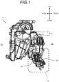
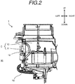
- Fig. 1 to Fig. 3 all illustrate a vehicle air-conditioning apparatus 1 of a first embodiment of the invention.
- Fig. 1 is a schematic side view illustrating a side view
- Fig. 2 is a schematic front view illustrating part of a front view
- Fig. 3 is a partial explanatory drawing of a portion indicated by a reference sign 1a in Fig. 1 with an evaporator cover 11 removed therefrom.
- the vehicle air-conditioning apparatus 1 of the first embodiment is configured to be mounted on a front portion of the vehicle, and includes a case member (case body) 10 and the case member (evaporator cover) 11.
- the evaporator cover 11 is mounted on the case body 10 to constitute a unit case C.
- the unit case C partitions between an internal space 80 and an external space 90.
- An evaporator 20 is disposed in the internal space 80 as illustrated in Fig. 3 .
- the vehicle air-conditioning apparatus 1 includes a blower apparatus (not illustrated). Air blown by the blower apparatus flows through the internal space 80, and is cooled down by the evaporator 20 in the course of being blown into a vehicle cabin.
- Air flowing through the internal space is changed in pressure (static pressure, dynamic pressure) in the internal space 80 by effects of factors such as a pressure (ram pressure) of the outside air received while the vehicle is travelling, an operating state of the blower apparatus, and a state of wind distribution to be blown into the vehicle cabin.
- a pressure ram pressure
- the evaporator 20 is a ventilation resistance member
- the pressure of air on the upstream side of the evaporator 20 is generally higher than that of air on the downstream side of the evaporator 20 (left side of the evaporator 20 in the drawing).
- this relationship may be inverted depending on the effects of the factors described above, and the pressure of air on the downstream side of the evaporator 20 may become instantaneously higher.
- the evaporator 20 is manufactured by a known process, and is formed of, for example, aluminum alloy or copper alloy.
- the evaporator 20 constitutes part of a refrigeration cycle. Coolant is supplied through a pipe 21, exchanges heat with air in the periphery, and is discharged through a pipe 22. The air after heat exchange with the evaporator 20 is cooled and generates condensed water. The condensed water flows downward of the evaporator 20, and is discharged to the external space 90 through a drain unit, which is not illustrated.
- the case body 10 and the evaporator cover 11 are formed of a resin such as polypropylene or ABS, and is manufactured by an injection molding process.
- the case body 10 and the evaporator cover 11 include vertical parting planes (10a, 11a) respectively, and constitute the unit case C when the evaporator cover 11 is mounted on the case body 10.
- the case body 10 and the evaporator cover 11 constitute a joint portion 12, which will be described later.
- condensed water generated by heat exchange flows from the evaporator 20 disposed in the internal space 80 of the case body 10, and is pooled on a bottom portion B of the joint portion.
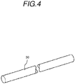
- a rod-shaped sealing member 30 is disposed on the bottom portion B of the joint portion illustrated in Fig. 4 in a compressed manner, and prevents the condensed water from leaking to the external space of the unit case C.
- Examples of a material used for the sealing member include rubber having resiliency used in general in the vehicle air-conditioning apparatus such as NBR or EPDM.
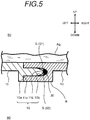
- Fig. 5 is an explanatory cross-sectional view taken along the line X-X in Fig. 3 with the evaporator cover 11 added thereto.
- the case body 10 and the evaporator cover 11 are fixed by a known fixing device such as screws, bolts, or other means such as claw fittings, which are not illustrated.
- the case body 10 includes the vertical parting plane 10a, and a depressed groove 10b is provided in the interior of the parting plane 10a.
- the evaporator cover 11 includes the vertical parting plane 11a, and is provided with a projecting portion 11b projecting from the parting plane 11a.
- the projecting portion 11b is inserted into the depressed groove 10b, and constitutes the joint portion 12 by an abutment between the parting plane 10a and the parting plane 11a.
- the rod-shaped sealing member 30 is compressed by a distal end of the projecting portion 11b and the depressed groove 10b therebetween while being held in the depressed groove 10b.
- a void S is present in addition to the compressed sealing member 30 in the space between the depressed groove 10b and the projecting portion 11b.
- the void S includes an inner void S1 present on the internal space 80 side of the sealing member 30 and an outer void S2 present on the external space 90 side of the sealing member 30.
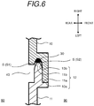
- Fig. 6 is an explanatory cross-sectional view taken along the line Y-Y in Fig. 3 with the evaporator cover 11 added thereto.
- a basic configuration is the same as that of the joint portion 12 illustrated in Fig. 5
- the configuration in Fig. 6 is different in that part of the case body 10 is notched and a communicating portion 40 is provided.
- the communicating portion 40 With the provision of the communicating portion 40, the internal space 80 and the inner void S1 communicate with each other to an extent that water can move without causing the capillary action. In other words, the ventilation resistance and the water circulation resistance are set to be low.
- Fig. 7 illustrates a portion indicated by a reference sign E in Fig. 3 in an enlarged scale, and is an explanatory drawing illustrating a portion of the rod-shaped sealing member 30 in the vicinity of an end portion on one side 30a.
- the parting plane 10a of the case body includes the depressed groove 10b that holds the sealing member 30 therein.
- the depressed groove 10b is provided at an upper end portion thereof with an output portion 50 that communicates the depressed groove 10b with the external space 90.
- the sealing member 30 extends from the output portion 50 to the external space 90, and the end portion on one side 30a is exposed to the external space 90. Accordingly, even after assembly of the evaporator cover 11 to the case body 10, whether or not the sealing member 30 is held in the interior of the joint portion 12 may be easily confirmed.
- the output portion 50 has a circular shape or a shape equivalent thereto.
- a cross-sectional area of the output portion 50 is set to be smaller than the cross-sectional area of the sealing member 30. Accordingly, even when an internal pressure of the internal space 80 of the unit case C varies and the variations in internal pressure is propagated to the output portion 50 through the communicating portion 40, a flow of air between the internal space 80 and the external space 90 is prevented since the sealing member 30 is compressed by the output portion 50, whereby the ventilation resistance and the water circulation resistance at the output portion 50 are increased. The ventilation resistance and the water circulation resistance are higher at the output portion 50 than those at the communicating portion 40.
- the communicating portion 40 is provided at a distance D1 below the output portion 50.
- the communicating portion 40 is provided below the output portion 50 and the communicating portion 40 and the output portion 50 are disposed in a crank shape in this manner. Therefore, even when the internal pressure of the internal space 80 varies and the inner void S1 has an effect of a motive pressure from the communicating portion 40, the effect on the output portion 50 may be reduced, and further reliable prevention of the flow of the air between the internal space 80 and the external space 90 is achieved.
- Fig. 8 is a schematic diagram illustrating the vehicle air-conditioning apparatus of the first embodiment of the invention. Referring now to Fig. 8 , a behavior that occurs when the internal pressure of part of the internal space 80 of the unit case C rises abruptly will be described.
- the internal pressure of the internal space 80 rises first, and a pressure P is applied to the inside of the joint portion 12. It is assumed in this case that the pressure in the internal space 80, specifically on the left side (the other side) of Fig. 8 , has risen instantaneously. Then, air A (air flowing into the inner void) flows into the inner void S1 via a communicating portion 40b. The air A then flows downward in the inner void S1 (hollow arrows), and pushes water introduced to the bottom portion B of the joint portion 12 from a water level W1 to a water level Wd. The water pushed out by the air A rises (black solid arrow) in the inner void S1 on the right side (one side) of Fig.
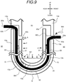
- Fig. 9 is a schematic diagram illustrating a comparative example for comparison with the invention.
- Fig. 9 is different from the schematic diagram of Fig. 8 in that the output portion 50a is provided below the communicating portion 40a.
- the behavior that occurs in a configuration in Fig. 9 is the same as that in Fig. 8 in that the internal pressure of the internal space 80 rises, the air A flows into the inner void S1 and pushes the water introduced to the bottom portion B of the joint portion, and thus the water rises in the inner void S1 on one side.
- the output portion 50a is provided below the communicating portion 40a, and thus water reaches the position of the output portion 50a as indicated by the water level W2.
- water may ooze out to the external space by the capillary action as indicated by a reference sign W4.
- the communicating portion 40a needs to be provided below the output portion 50a as illustrated in Fig. 7 and Fig. 8 .
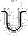
- Fig. 10 is a schematic diagram illustrating a vehicle air-conditioning apparatus of a second embodiment of the invention. There are two points different from the first embodiment illustrated in Fig. 8 . A first different point is that a cross-sectional area of the communicating portion on one side 40a is smaller than that of the communicating portion on the other side 40b, and a second different point is that the communicating portion on one side 40a is provided below the communicating portion on the other side 40b.
- the communicating portion on one side 40a illustrated in Fig. 10 is illustrated to be smaller in cross-sectional area than the communicating portion on the other side 40b. More specifically, the communicating portion on one side 40a is provided to be higher in ventilation resistance than the communicating portion on the other side 40b. In this configuration, even though the internal pressure of the internal space 80 rises unevenly, a change in pressure via the communicating portion on one side 40a can hardly be propagated to the inner void S1. Therefore, even though the water is discharged from the communicating portion 40, the discharging portion may always be set to the communicating portion 40a as indicated by the reference sign W3.
- the water discharging portion is provided at a position farther from the electronic components to enhance reliability of the vehicle air-conditioning apparatus 1.
- the communicating portion on one side 40a illustrated in Fig. 10 is provided at a distance D2 below the communicating portion on the other side 40b. In this configuration, the water can easily be discharged from the communicating portion on one side 40a provided below. As described in the first different point, even though the internal pressure of the internal space 80 rises unevenly, reliability of the vehicle air-conditioning apparatus 1 may be improved always as the communicating portion 40a as indicated by the reference sign W3.
- the first different point and the second different point have been described separately thus far.
- the configuration in which both of the two different points are reflected is further preferable as illustrated in Fig. 10 . Further improvement of the reliability of the vehicle air-conditioning apparatus 1 is achieved.
- Fig. 11 is a schematic diagram illustrating a vehicle air-conditioning apparatus of a third embodiment of the invention. There are two different points from the first embodiment illustrated in Fig. 8 . A first different point is that the output portion 50a on one side is provided below the output portion 50b on the other side, and a second different point is that the communicating portion is provided only as the communicating portion on one side 40a and is not provided on the other side (the left side of Fig. 11 ).
- the communicating portion 40a on the lower side of the output portion 50 in this manner while reflecting the first and second different points, water introduced, for example, into the inner void S1 due to variations in internal pressure may rise on one side (right side in the drawing) of the inner void S1 and be discharged from the communicating portion 40a.
- the output portion on the other side 50b is at a distance D4 higher than the water level W1 before an occurrence of the variation in internal pressure, that is, is approximately at a distance D3 higher than the communicating portion on one side 40a even though the water introduced into the inner void S1 rises on the other side (the left side of Fig. 11 ) of the inner void S1.
- the water may be prevented from reaching the output portion 50b as indicated by a reference sign W5 with high probability.
- the communicating portion on the other side cannot be provided because of a constraint relating to the water discharge portion toward an injection mold or the internal space, easy confirmation of missing of the sealing member and prevention of a water leak to the external space are achieved by employing the third embodiment.
- the mode in which the evaporator cover 11 is mounted on a side surface of the case body 10 has been described as an example thus far, modification without departing from the gist of the invention is included within a range of the invention as a matter of course.
- the invention may be applied to vehicle air-conditioning apparatuses having a configuration in which the case body 10 is provided with a projecting portion and the evaporator cover 11 is provided with a depressed groove, or a configuration in which the case body 10 is composed of a plurality of sub cases each having a vertical parting plane, so that rain water and condensed water are pooled on the joint portion of the parting planes.
- the vehicle air-conditioning apparatus of the invention may be manufactured industrially, and may be an object for commercial dealings. Therefore, the vehicle air-conditioning apparatus has an economical value and is industrially applicable.
Landscapes
- Physics & Mathematics (AREA)
- Thermal Sciences (AREA)
- Engineering & Computer Science (AREA)
- Mechanical Engineering (AREA)
- Air-Conditioning For Vehicles (AREA)
Abstract
Description
- The present invention relates to an air-conditioning apparatus that is to be mounted on a vehicle.
- A vehicle air-conditioning apparatus is configured to flow air into an internal space of a unit case, condition the temperature thereof, then blow out the conditioned air into a vehicle cabin, and in some cases, sucks rainwater, mist, snow, and the like existing outside the vehicle. In addition, in the course of temperature conditioning, there may be a case where air is cooled by operating an evaporator, which is disposed in the internal space, so that condensed water may be generated.
- When the unit case is configured to be, for example, a vertically partitioned type, which allows the case to be divided into left and right pieces, a vertical parting plane is formed. Therefore, the unit case requires a special design that prevents rainwater or condensed water from leaking from a bottom portion of the unit case. In view of this point, as disclosed in
Patent Literature 1, for example, a configuration having a depression/projection joint portion that holds a rod-shaped sealing member in a compressed manner in a lower portion of the unit case at a portion where condensed water may be pooled is known. - According to
Patent Literature 1, the depression/projection joint portion includes remaining voids that cannot be filled with the sealing member in addition to the compressed rod-shaped sealing member. Therefore, if condensed water enters the unit case and an internal pressure therein is increased, the water that has entered the voids may reach an end of the sealing member disposed above the portion where the condensed water is pooled. In addition, according toPatent Literature 1, the water which has lost a way to go may proceed around a distal end of the sealing member and leak from the joint portion between the left and right pieces of the unit case to an outer wall side. In order to avoid such a leak, a configuration including communicating portions that communicate the internal space of the unit case with the voids at both end portions of a holding depressed groove, which is a part of the depression/projection joint portion for holding the sealing member, is proposed. With the communicating portions configured in this manner, even though the internal pressure in the unit case rises, a pressure that acts on both ends of the water pooled between the communicating portions may be regulated to the same pressure as the internal pressure of the unit case. Therefore, the water entering the voids is prevented from reaching the end of the sealing member. - Patent Literature 1 :
JP Patent No.4072301B - However, in
Patent Literature 1, the fact that the internal pressure in the unit case non-uniformly rises when the internal pressure rises is not considered. The condensed water is pooled across the evaporator from an upstream side to a downstream side thereof. Therefore, the pressure in the space is more likely to rise on the upstream side of a condenser in principle. However, when an opening degree of a blowout door disposed on the downstream side of the condenser is controlled, the pressure in a space on the downstream side of the evaporator may rise instantaneously. In this manner, even though the communicating portions are provided as in Japanese Patent No.4072301 - In addition, in
Patent Literature 1, the rod-shaped sealing member is held in the interior of the holding depressed groove. Therefore, when an inspection is performed to check the presence of the sealing member after assembly of the vehicle air-conditioning apparatus has terminated in a production process, the presence of the sealing member cannot be recognized from outside of the unit case, and thus missing part may occur. Therefore, a configuration having leading holes that communicate the holding depressed groove with an outer wall surface of the unit case and leading out an end of the rod-shaped sealing member to the outer wall surface side of the unit case (the side of an external space) to enable a visual inspection is conceivable. - However, if the communication portions are provided at the end portions of the holding depressed grooves as in
Patent Literature 1, the rise in internal pressure in the unit case is transferred to the holding depressed groove via the communication portions, and in addition, air leaks to the external space of the unit case through the leading holes. Consequently, the water entering the voids at this time may leak to the external space of the unit case through the leading holes. - It is an object of the invention to provide a vehicle air-conditioning apparatus that achieves easy inspection of missing of a sealing member by leading ends of a rod-shaped sealing member out to an external space of a unit case, in which water pooled in a holding depressed groove is prevented from leaking out to an outer wall surface side of the unit case even though an internal pressure in the unit case rises.
- This disclosure provides a vehicle air-conditioning apparatus (1) including: a unit case (C) having an internal space (80) and formed by assembling a plurality of case members (10, 11) each including a vertical parting plane (10a, 11a); a joint portion (12) including a depressed groove (10b) provided on the parting plane (10a) of one of the case members (10) and a projecting portion (11b) provided on the parting plane (11a) of the other case member (11) and to be inserted into the depressed groove (10b); and a rod-shaped sealing member (30) disposed on a bottom portion (B) and in an interior of the joint portion in a compressed manner, in which the unit case (C) includes an output portion (50) that communicates the depressed groove with an external space (19) of the unit case, and leads ends (30a, 30b) of the rod-shaped sealing member out to the external space, and a communicating portion (40) that communicates the depressed groove with the internal space and is provided below the output portions.
- Accordingly, the ends of the sealing member are led out to the external space of the unit case, inspection of missing of the sealing member is easily achieved. In addition, the communicating portion that communicates the depressed groove with the internal space of the unit case is provided below the output portion that leads the seal member out to the external space of the unit case. Therefore, even though water pooled in a bottom portion of the unit case runs in the depressed groove due to the rise in internal pressure in the unit case and is guided upward along the sealing member, the water reaches the depressed groove provided below, that is, on the upstream side of the output portions first. The water guided upward is discharged into the internal space of the unit case through the communicating portion, so that the water pooled in the depressed groove may be prevented from leaking to the external space.
- Preferably, the communicating portion includes a communicating portion on one side (40a) provided on one side of the bottom portion of the joint portion and a communicating portion on the other side (40b) provided on the other side thereof, and the communicating portion on one side has higher ventilation resistance than the communicating portion on the other side.
- Even though the pressure in the internal space of the unit case rises, it does not necessarily rise uniformly. Therefore, if the water pooled in the depressed groove moves upward of the unit case due to the rise of the pressure in the internal space, the direction that the water moves with respect to the bottom portion of the unit case is unknown. However, according to the configuration described above, since the ventilation resistance at the communicating portion on one side is set to be higher than that at the communicating portion on the other side, a change in water level through the communicating portion on the other side may be made more sensitive, so that the water level rises toward the communicating portion on one side. In this configuration, even though the rise in pressure in the internal space is not uniform, the water to be discharged into the internal space is always output through the communicating portion on one side. Accordingly, an improvement of the quality is achieved.
- Preferably, the communicating portion includes the communicating portion on one side (40a) provided on one side of the bottom portion of the joint portion and the communicating portion on the other side (40b) provided on the other side thereof, and the communicating portion on one side is provided below the communicating portion on the other side. In this configuration, since the communicating portion on one side is provided below the communicating portion on the other side, the water to be discharged into the internal space is always output through the communicating portion on one side even though the rise in pressure in the internal space is not uniform. Accordingly, a quality improvement is achieved.
- Preferably, the output portion includes an output portion on the other side (50b) provided on the other side of the bottom portion of the joint portion and the communicating portion includes the communicating portion on one side (40a) provided on one side of the bottom portion of the joint portion, and the communicating portion on one side is provided below the output portion on the other side. Even though the communicating portion cannot be provided on the other side of the bottom portion of the joint portion from some reasons, a level difference between a surface of the water pooled in the bottom portion of the unit case and the output portion may be set to be large enough by providing the communicating portion on one side below the output portion on the other side even when the water pooled in the depressed groove rises toward the other side of the parting plane, so that the water may be prevented from leaking out to the external space.
- Preferably, the output portion includes an output portion on one side (50a) provided on one side of the bottom portion of the joint portion and the output portion on the other side (50b) provided on the other side thereof, and the communicating portion includes the communicating portion on one side (40a) provided on one side of the bottom portion of the joint portion and the communicating portion on the other side (40b) provided on the other side thereof, the communicating portion on one side is provided below the output portion on one side, and the communicating portion on the other side is provided below the output portion on the other side. Irrespective of the direction in which the water pooled in the depressed groove rises due to a rise in pressure in the unit case, either to one side or to the other side with respect to the bottom of the parting plane, the water may be prevented from reaching the output portion.
- Preferably, a portion between the output portion and the sealing member has a higher ventilation resistance than the communicating portion. Water rose in the depressed groove may be discharged further reliably into the internal space of the unit case.
- Preferably, the joint portion and the sealing member define an inner void (S1) on the internal space side with respect to the sealing member, and the communicating portion is provided so as to communicate the inner void with the internal space.
- The invention provides the vehicle air-conditioning apparatus that allows easy inspections of missing of the sealing member and prevents water from leaking into the external space of the unit case even though the internal pressure rises.
-
-
Fig. 1 is a schematic side view illustrating a side of a vehicle air-conditioning apparatus of a first embodiment of the invention; -
Fig. 2 is a schematic front view illustrating part of a front of the vehicle air-conditioning apparatus of the first embodiment of the invention; -
Fig. 3 is a partial explanatory drawing illustrating the vehicle air-conditioning apparatus of the first embodiment of the invention, in which an evaporator cover is removed from a portion indicated by areference sign 1a inFig. 1 ; -
Fig. 4 is a perspective view illustrating a rod-shaped sealing member inFig. 3 ; -
Fig. 5 is an explanatory cross-sectional view taken along the line X-X inFig. 3 with the evaporator cover added thereto; -
Fig. 6 is an explanatory cross-sectional view taken along the line Y-Y inFig. 3 with the evaporator cover added thereto; -
Fig. 7 is a partial explanatory drawing illustrating a portion indicated by a reference sign E inFig. 3 in an enlarged scale; -
Fig. 8 is a schematic diagram illustrating the vehicle air-conditioning apparatus of the first embodiment of the invention; -
Fig. 9 is a schematic diagram illustrating a comparative example for comparison with the invention; -
Fig. 10 is a schematic diagram illustrating a vehicle air-conditioning apparatus of a second embodiment of the invention; and -
Fig. 11 is a schematic diagram illustrating a vehicle air-conditioning apparatus of a third embodiment of the invention. - Referring now to the attached drawings, a mode of the invention will be described. An embodiment described below is an example of the invention, and the invention is not limited to the following embodiment. In the specification and the drawings, components having identical reference signs indicate the same components. Various modifications may be made for achieving advantageous effects of the invention.
-
Fig. 1 to Fig. 3 all illustrate a vehicle air-conditioning apparatus 1 of a first embodiment of the invention.Fig. 1 is a schematic side view illustrating a side view,Fig. 2 is a schematic front view illustrating part of a front view, andFig. 3 is a partial explanatory drawing of a portion indicated by areference sign 1a inFig. 1 with anevaporator cover 11 removed therefrom. The vehicle air-conditioning apparatus 1 of the first embodiment is configured to be mounted on a front portion of the vehicle, and includes a case member (case body) 10 and the case member (evaporator cover) 11. Theevaporator cover 11 is mounted on thecase body 10 to constitute a unit case C. The unit case C partitions between aninternal space 80 and anexternal space 90. Anevaporator 20 is disposed in theinternal space 80 as illustrated inFig. 3 . - The vehicle air-
conditioning apparatus 1 includes a blower apparatus (not illustrated). Air blown by the blower apparatus flows through theinternal space 80, and is cooled down by theevaporator 20 in the course of being blown into a vehicle cabin. - Air flowing through the internal space is changed in pressure (static pressure, dynamic pressure) in the
internal space 80 by effects of factors such as a pressure (ram pressure) of the outside air received while the vehicle is travelling, an operating state of the blower apparatus, and a state of wind distribution to be blown into the vehicle cabin. For example, inFig. 3 , since theevaporator 20 is a ventilation resistance member, the pressure of air on the upstream side of the evaporator 20 (right side of theevaporator 20 in the drawing) is generally higher than that of air on the downstream side of the evaporator 20 (left side of theevaporator 20 in the drawing). However, this relationship may be inverted depending on the effects of the factors described above, and the pressure of air on the downstream side of theevaporator 20 may become instantaneously higher. - The
evaporator 20 is manufactured by a known process, and is formed of, for example, aluminum alloy or copper alloy. Theevaporator 20 constitutes part of a refrigeration cycle. Coolant is supplied through apipe 21, exchanges heat with air in the periphery, and is discharged through apipe 22. The air after heat exchange with theevaporator 20 is cooled and generates condensed water. The condensed water flows downward of theevaporator 20, and is discharged to theexternal space 90 through a drain unit, which is not illustrated. - The
case body 10 and theevaporator cover 11 are formed of a resin such as polypropylene or ABS, and is manufactured by an injection molding process. In the first embodiment, thecase body 10 and theevaporator cover 11 include vertical parting planes (10a, 11a) respectively, and constitute the unit case C when theevaporator cover 11 is mounted on thecase body 10. Thecase body 10 and theevaporator cover 11 constitute ajoint portion 12, which will be described later. - As illustrated in
Fig. 3 , condensed water generated by heat exchange flows from theevaporator 20 disposed in theinternal space 80 of thecase body 10, and is pooled on a bottom portion B of the joint portion. A rod-shaped sealingmember 30 is disposed on the bottom portion B of the joint portion illustrated inFig. 4 in a compressed manner, and prevents the condensed water from leaking to the external space of the unit case C. Examples of a material used for the sealing member include rubber having resiliency used in general in the vehicle air-conditioning apparatus such as NBR or EPDM. -
Fig. 5 is an explanatory cross-sectional view taken along the line X-X inFig. 3 with theevaporator cover 11 added thereto. Thecase body 10 and theevaporator cover 11 are fixed by a known fixing device such as screws, bolts, or other means such as claw fittings, which are not illustrated. Thecase body 10 includes thevertical parting plane 10a, and adepressed groove 10b is provided in the interior of theparting plane 10a. Theevaporator cover 11 includes thevertical parting plane 11a, and is provided with a projectingportion 11b projecting from theparting plane 11a. The projectingportion 11b is inserted into thedepressed groove 10b, and constitutes thejoint portion 12 by an abutment between the partingplane 10a and theparting plane 11a. The rod-shaped sealingmember 30 is compressed by a distal end of the projectingportion 11b and thedepressed groove 10b therebetween while being held in thedepressed groove 10b. A void S is present in addition to the compressed sealingmember 30 in the space between thedepressed groove 10b and the projectingportion 11b. The void S includes an inner void S1 present on theinternal space 80 side of the sealingmember 30 and an outer void S2 present on theexternal space 90 side of the sealingmember 30. - Rainwater flowing through the blower apparatus and condensed water and the like Aq flowing from the
evaporator 20 are pooled on the bottom portion B of the joint portion. At thejoint portion 12 where theparting plane 10a of the case body and theparting plane 11a of the evaporator cover are in abutment with each other, surface roughness to an extent that allows water molecules to move thereon exists, and thus the water reaches the inner void S1 coupled with a capillary action. Therefore, the internal pressure of theinternal space 80 rises, and when a pressure is applied to the rainwater or the condensed water and the like Aq flowed from theevaporator 20, a volume of water that may enter the inner void S1 increases and a water level rises upward along the inner void S1. In contrast, since the sealingmember 30 is compressed between thedepressed groove 10b and the projectingportion 11b, the water does not reach the outer void S2, and thus is prevented from leaking to theexternal space 90. -
Fig. 6 is an explanatory cross-sectional view taken along the line Y-Y inFig. 3 with theevaporator cover 11 added thereto. Although a basic configuration is the same as that of thejoint portion 12 illustrated inFig. 5 , the configuration inFig. 6 is different in that part of thecase body 10 is notched and a communicatingportion 40 is provided. With the provision of the communicatingportion 40, theinternal space 80 and the inner void S1 communicate with each other to an extent that water can move without causing the capillary action. In other words, the ventilation resistance and the water circulation resistance are set to be low. -
Fig. 7 illustrates a portion indicated by a reference sign E inFig. 3 in an enlarged scale, and is an explanatory drawing illustrating a portion of the rod-shaped sealingmember 30 in the vicinity of an end portion on oneside 30a. Theparting plane 10a of the case body includes thedepressed groove 10b that holds the sealingmember 30 therein. Thedepressed groove 10b is provided at an upper end portion thereof with anoutput portion 50 that communicates thedepressed groove 10b with theexternal space 90. The sealingmember 30 extends from theoutput portion 50 to theexternal space 90, and the end portion on oneside 30a is exposed to theexternal space 90. Accordingly, even after assembly of theevaporator cover 11 to thecase body 10, whether or not the sealingmember 30 is held in the interior of thejoint portion 12 may be easily confirmed. - The
output portion 50 has a circular shape or a shape equivalent thereto. A cross-sectional area of theoutput portion 50 is set to be smaller than the cross-sectional area of the sealingmember 30. Accordingly, even when an internal pressure of theinternal space 80 of the unit case C varies and the variations in internal pressure is propagated to theoutput portion 50 through the communicatingportion 40, a flow of air between theinternal space 80 and theexternal space 90 is prevented since the sealingmember 30 is compressed by theoutput portion 50, whereby the ventilation resistance and the water circulation resistance at theoutput portion 50 are increased. The ventilation resistance and the water circulation resistance are higher at theoutput portion 50 than those at the communicatingportion 40. - In
Fig. 7 , the communicatingportion 40 is provided at a distance D1 below theoutput portion 50. The communicatingportion 40 is provided below theoutput portion 50 and the communicatingportion 40 and theoutput portion 50 are disposed in a crank shape in this manner. Therefore, even when the internal pressure of theinternal space 80 varies and the inner void S1 has an effect of a motive pressure from the communicatingportion 40, the effect on theoutput portion 50 may be reduced, and further reliable prevention of the flow of the air between theinternal space 80 and theexternal space 90 is achieved. -
Fig. 8 is a schematic diagram illustrating the vehicle air-conditioning apparatus of the first embodiment of the invention. Referring now toFig. 8 , a behavior that occurs when the internal pressure of part of theinternal space 80 of the unit case C rises abruptly will be described. - The internal pressure of the
internal space 80 rises first, and a pressure P is applied to the inside of thejoint portion 12. It is assumed in this case that the pressure in theinternal space 80, specifically on the left side (the other side) ofFig. 8 , has risen instantaneously. Then, air A (air flowing into the inner void) flows into the inner void S1 via a communicatingportion 40b. The air A then flows downward in the inner void S1 (hollow arrows), and pushes water introduced to the bottom portion B of thejoint portion 12 from a water level W1 to a water level Wd. The water pushed out by the air A rises (black solid arrow) in the inner void S1 on the right side (one side) ofFig. 8 , and reaches a communicatingportion 40a. The pushed water now tries to proceed to either one of a route to be discharged from the communicatingportion 40a to theinternal space 80 or a route proceeding toward anoutput portion 50a. Since the ventilation resistance and the water circulation resistance at theoutput portion 50a are high, water does not reach theoutput portion 50a and is discharged from the communicatingportion 40a to theinternal space 80 as indicated by a reference sign W3. - Since the sealing
member 30 is held in the interior of thejoint portion 12 in a compressed manner during this behavior, movement of water from the inner void S1 to the outer void S2 does not occur. Therefore, the water is prevented from leaking out to theexternal space 90 even when the internal pressure of theinternal space 80 varies. - The case where the pressure of the
internal space 80, specifically the pressure on the left side (the other side) inFig. 8 rises has been described in conjunction withFig. 8 . However, in a case where the pressure on the right side (one side) inFig. 8 rises, a laterally inverted behavior occurs, and a leak of the water to theexternal space 90 is prevented. -
Fig. 9 is a schematic diagram illustrating a comparative example for comparison with the invention.Fig. 9 is different from the schematic diagram ofFig. 8 in that theoutput portion 50a is provided below the communicatingportion 40a. The behavior that occurs in a configuration inFig. 9 is the same as that inFig. 8 in that the internal pressure of theinternal space 80 rises, the air A flows into the inner void S1 and pushes the water introduced to the bottom portion B of the joint portion, and thus the water rises in the inner void S1 on one side. - However, in the configuration in
Fig. 9 , theoutput portion 50a is provided below the communicatingportion 40a, and thus water reaches the position of theoutput portion 50a as indicated by the water level W2. As described above, even with the configuration in which the sealingmember 30 is led out from theoutput portion 50 in the compressed manner, water may ooze out to the external space by the capillary action as indicated by a reference sign W4. According to the comparative example illustrated inFig. 9 , prevention of a water leak is not ensured, and thus the communicatingportion 40a needs to be provided below theoutput portion 50a as illustrated inFig. 7 andFig. 8 . -
Fig. 10 is a schematic diagram illustrating a vehicle air-conditioning apparatus of a second embodiment of the invention. There are two points different from the first embodiment illustrated inFig. 8 . A first different point is that a cross-sectional area of the communicating portion on oneside 40a is smaller than that of the communicating portion on theother side 40b, and a second different point is that the communicating portion on oneside 40a is provided below the communicating portion on theother side 40b. - First of all, the first different point will be described. The communicating portion on one
side 40a illustrated inFig. 10 is illustrated to be smaller in cross-sectional area than the communicating portion on theother side 40b. More specifically, the communicating portion on oneside 40a is provided to be higher in ventilation resistance than the communicating portion on theother side 40b. In this configuration, even though the internal pressure of theinternal space 80 rises unevenly, a change in pressure via the communicating portion on oneside 40a can hardly be propagated to the inner void S1. Therefore, even though the water is discharged from the communicatingportion 40, the discharging portion may always be set to the communicatingportion 40a as indicated by the reference sign W3. In the vehicle air-conditioning apparatus 1, since electronic components such as an electric heat generating apparatus or an ion generator are disposed on the downstream side of theevaporator 20, prevention of splash of liquidized water is desired. Therefore, the water discharging portion is provided at a position farther from the electronic components to enhance reliability of the vehicle air-conditioning apparatus 1. - Subsequently, the second different point will be described. The communicating portion on one
side 40a illustrated inFig. 10 is provided at a distance D2 below the communicating portion on theother side 40b. In this configuration, the water can easily be discharged from the communicating portion on oneside 40a provided below. As described in the first different point, even though the internal pressure of theinternal space 80 rises unevenly, reliability of the vehicle air-conditioning apparatus 1 may be improved always as the communicatingportion 40a as indicated by the reference sign W3. - The first different point and the second different point have been described separately thus far. However, the configuration in which both of the two different points are reflected is further preferable as illustrated in
Fig. 10 . Further improvement of the reliability of the vehicle air-conditioning apparatus 1 is achieved. -
Fig. 11 is a schematic diagram illustrating a vehicle air-conditioning apparatus of a third embodiment of the invention. There are two different points from the first embodiment illustrated inFig. 8 . A first different point is that theoutput portion 50a on one side is provided below theoutput portion 50b on the other side, and a second different point is that the communicating portion is provided only as the communicating portion on oneside 40a and is not provided on the other side (the left side ofFig. 11 ). - By providing the communicating
portion 40a on the lower side of theoutput portion 50 in this manner while reflecting the first and second different points, water introduced, for example, into the inner void S1 due to variations in internal pressure may rise on one side (right side in the drawing) of the inner void S1 and be discharged from the communicatingportion 40a. In contrast, the output portion on theother side 50b is at a distance D4 higher than the water level W1 before an occurrence of the variation in internal pressure, that is, is approximately at a distance D3 higher than the communicating portion on oneside 40a even though the water introduced into the inner void S1 rises on the other side (the left side ofFig. 11 ) of the inner void S1. Therefore, the water may be prevented from reaching theoutput portion 50b as indicated by a reference sign W5 with high probability. In the case where the communicating portion on the other side cannot be provided because of a constraint relating to the water discharge portion toward an injection mold or the internal space, easy confirmation of missing of the sealing member and prevention of a water leak to the external space are achieved by employing the third embodiment. - Although the mode in which the
evaporator cover 11 is mounted on a side surface of thecase body 10 has been described as an example thus far, modification without departing from the gist of the invention is included within a range of the invention as a matter of course. For example, in contrast to the embodiments illustrated in the drawings, the invention may be applied to vehicle air-conditioning apparatuses having a configuration in which thecase body 10 is provided with a projecting portion and theevaporator cover 11 is provided with a depressed groove, or a configuration in which thecase body 10 is composed of a plurality of sub cases each having a vertical parting plane, so that rain water and condensed water are pooled on the joint portion of the parting planes. - The vehicle air-conditioning apparatus of the invention may be manufactured industrially, and may be an object for commercial dealings. Therefore, the vehicle air-conditioning apparatus has an economical value and is industrially applicable.
-
- 1 vehicle air-conditioning apparatus
- 1a part of vehicle air-conditioning apparatus (lower portion of evaporator cover)
- 10 case member (case body)
- 10a parting plane (parting plane of case body)
- 10b depressed groove
- 11 case member (evaporator cover)
- 11a parting plane (parting plane of evaporator cover)
- 11b projecting portion
- 12 joint portion
- 20 evaporator
- 30 rod-shaped sealing member
- 30a end portion on one side of the sealing member
- 30b end portion on the other side of the sealing member
- 40 communicating portion
- 40a communicating portion on one side
- 40b communicating portion on the other side
- 50 output portion
- 50a output portion on one side
- 50b output portion on the other side
- 80 internal space
- 90 external space
- A air flowing into inner void
- Aq rainwater, condensed water, and the like
- B bottom portion of joint portion
- C unit case
- E part of vehicle air-conditioning apparatus (vicinity of output portion)
- S void
- S1 inner void
- S2 outer void
- P internal pressure (internal pressure in unit case)
- W1 water level
- W2 water level
- W3 discharged water
- W4 discharged water
- W5 water level
- Wd water level
- D1 distance
- D2 distance
- D3 distance
Claims (7)
- A vehicle air-conditioning apparatus (1) comprising:a unit case (C) having an internal space (80) and formed by assembling a plurality of case members (10,11) each including a vertical parting plane (10a,11a);a joint portion (12) including a depressed groove (10b) provided on the parting plane (10a) of one of the case members (10) and a projecting portion (11b) provided on the parting plane (11a) of the other case member (11) and to be inserted into the depressed groove (10b); anda rod-shaped sealing member (30) disposed on a bottom portion (B) and in an interior of the joint portion in a compressed manner, whereinthe unit case (C) includes: an output portion (50) that communicates the depressed groove with an external space (19) of the unit case, and leads ends (301,30b) of the rod-shaped sealing member out to the external space, anda communicating portion (40) that communicates the depressed groove with the internal space and is provided below the output portion.
- The vehicle air-conditioning apparatus according to Claim 1, wherein
the communicating portion includes: the communicating portion on one side (40a) provided on one side of the bottom portion of the joint portion and the communicating portion on the other side (40b) provided on the other side thereof, and ventilation resistance at the communicating portion on one side is higher than that at the communicating portion on the other side. - The vehicle air-conditioning apparatus according to Claim 1 or 2, wherein
the communicating portion includes the communicating portion on one side (40a) provided on one side of the bottom portion of the joint portion and the communicating portion on the other side (40b) provided on the other side thereof, and
the communicating portion on one side is provided below the communicating portion on the other side. - The vehicle air-conditioning apparatus according to Claim 1, wherein
the output portion includes an output portion on the other side (50b) provided on the other side of the bottom portion of the joint portion,
the communicating portion includes the communicating portion on one side (40a) provided on one side of the bottom portion of the joint portion, and
the communicating portion on one side is provided below the output portion on the other side. - The vehicle air-conditioning apparatus according to Claim 1, wherein
the output portion includes an output portion on one side (50a) provided on one side of the bottom portion of the joint portion and the output portion on the other side (50b) provided on the other side thereof,
the communicating portion includes the communicating portion on one side (40a) provided on one side of the bottom portion of the joint portion and the communicating portion on the other side (40b) provided on the other side thereof,
the communicating portion on one side is provided below the output portion on one side, and
the communicating portion on the other side is provided below the output portion on the other side. - The vehicle air-conditioning apparatus according to any one of Claims 1 to 5, wherein
a portion between the output portion and the sealing member has a higher ventilation resistance than the communicating portion. - The vehicle air-conditioning apparatus according to any one of Claims 1 to 6, wherein
the joint portion and the sealing member define an inner void (S1) on the internal space side with respect to the sealing member, and
the communicating portion is provided so as to communicate the inner void with the internal space.
Applications Claiming Priority (1)
| Application Number | Priority Date | Filing Date | Title |
|---|---|---|---|
| JP2016032979A JP6542692B2 (en) | 2016-02-24 | 2016-02-24 | Vehicle air conditioner |
Publications (2)
| Publication Number | Publication Date |
|---|---|
| EP3210805A1 true EP3210805A1 (en) | 2017-08-30 |
| EP3210805B1 EP3210805B1 (en) | 2018-11-07 |
Family
ID=58016559
Family Applications (1)
| Application Number | Title | Priority Date | Filing Date |
|---|---|---|---|
| EP17155117.9A Active EP3210805B1 (en) | 2016-02-24 | 2017-02-08 | Vehicle air-conditioning apparatus |
Country Status (2)
| Country | Link |
|---|---|
| EP (1) | EP3210805B1 (en) |
| JP (1) | JP6542692B2 (en) |
Citations (5)
| Publication number | Priority date | Publication date | Assignee | Title |
|---|---|---|---|---|
| JPH0472301B2 (en) | 1986-10-27 | 1992-11-17 | Nakamichi Corp | |
| JPH10100642A (en) * | 1996-08-05 | 1998-04-21 | Denso Corp | Vehicle air conditioner |
| JP2002274163A (en) * | 2001-03-14 | 2002-09-25 | Denso Corp | Vehicle air conditioner |
| JP2007083956A (en) * | 2005-09-26 | 2007-04-05 | Denso Corp | Air conditioner for vehicles |
| JP2007099056A (en) * | 2005-10-04 | 2007-04-19 | Calsonic Kansei Corp | Waterproof structure |
Family Cites Families (3)
| Publication number | Priority date | Publication date | Assignee | Title |
|---|---|---|---|---|
| JPS63137011U (en) * | 1987-02-27 | 1988-09-08 | ||
| JP2000016057A (en) * | 1998-07-03 | 2000-01-18 | Mitsubishi Heavy Ind Ltd | Air conditioner for vehicle |
| JP4072301B2 (en) * | 2000-02-03 | 2008-04-09 | カルソニックカンセイ株式会社 | Air conditioner for vehicles |
-
2016
- 2016-02-24 JP JP2016032979A patent/JP6542692B2/en active Active
-
2017
- 2017-02-08 EP EP17155117.9A patent/EP3210805B1/en active Active
Patent Citations (6)
| Publication number | Priority date | Publication date | Assignee | Title |
|---|---|---|---|---|
| JPH0472301B2 (en) | 1986-10-27 | 1992-11-17 | Nakamichi Corp | |
| JPH10100642A (en) * | 1996-08-05 | 1998-04-21 | Denso Corp | Vehicle air conditioner |
| US5954578A (en) * | 1996-08-05 | 1999-09-21 | Denso Corporation | Air conditioner for a vehicle |
| JP2002274163A (en) * | 2001-03-14 | 2002-09-25 | Denso Corp | Vehicle air conditioner |
| JP2007083956A (en) * | 2005-09-26 | 2007-04-05 | Denso Corp | Air conditioner for vehicles |
| JP2007099056A (en) * | 2005-10-04 | 2007-04-19 | Calsonic Kansei Corp | Waterproof structure |
Also Published As
| Publication number | Publication date |
|---|---|
| JP2017149245A (en) | 2017-08-31 |
| JP6542692B2 (en) | 2019-07-10 |
| EP3210805B1 (en) | 2018-11-07 |
Similar Documents
| Publication | Publication Date | Title |
|---|---|---|
| WO2014129115A1 (en) | Water discharge device and air conditioning device with same | |
| JP2005200007A (en) | Vehicle cowl structure furnished with air pipe | |
| US20140144605A1 (en) | Motor vehicle air conditioning unit | |
| EP3210805B1 (en) | Vehicle air-conditioning apparatus | |
| US20030151250A1 (en) | Mounting structure for tubular member | |
| EP0778180A1 (en) | A container for an electronic control unit | |
| CN204774489U (en) | Air conditioner device of vehicle | |
| US11655989B2 (en) | Outdoor unit of air-conditioning apparatus | |
| KR101216128B1 (en) | Pipe fixing member of evaporator for automotive vehicles | |
| CN102445042A (en) | refrigerator and air-cooled refrigerator | |
| JP2001315525A (en) | Drain structure of air conditioner for vehicle | |
| EP3078518B1 (en) | Vehicle air-conditioning apparatus | |
| WO2013128804A1 (en) | Vehicle air conditioning device | |
| JPWO2018123111A1 (en) | Air conditioner | |
| US10883740B2 (en) | Indoor unit for an air-conditioning apparatus | |
| KR101558006B1 (en) | A Radiator header tank assembling structure for a vehicle | |
| JP4547246B2 (en) | Air conditioner for vehicles | |
| JP2011152850A (en) | Air-conditioning unit for vehicle | |
| JP2000158937A (en) | Cooler unit | |
| KR20100086773A (en) | Air conditioning case for automotive vehicles | |
| JPH10119558A (en) | Seal cap of air conditioner for automobile | |
| US20250383027A1 (en) | Valve Apparatus, In Particular for a Housing of an Electronic and/or Electrical Device, as well as a Method for Production Thereof | |
| KR101458455B1 (en) | Air conditioning system for automotive vehicles | |
| JP4321387B2 (en) | Air conditioner for vehicles | |
| JP2015217916A (en) | Air conditioner for vehicles |
Legal Events
| Date | Code | Title | Description |
|---|---|---|---|
| PUAI | Public reference made under article 153(3) epc to a published international application that has entered the european phase |
Free format text: ORIGINAL CODE: 0009012 |
|
| STAA | Information on the status of an ep patent application or granted ep patent |
Free format text: STATUS: THE APPLICATION HAS BEEN PUBLISHED |
|
| AK | Designated contracting states |
Kind code of ref document: A1 Designated state(s): AL AT BE BG CH CY CZ DE DK EE ES FI FR GB GR HR HU IE IS IT LI LT LU LV MC MK MT NL NO PL PT RO RS SE SI SK SM TR |
|
| AX | Request for extension of the european patent |
Extension state: BA ME |
|
| STAA | Information on the status of an ep patent application or granted ep patent |
Free format text: STATUS: REQUEST FOR EXAMINATION WAS MADE |
|
| 17P | Request for examination filed |
Effective date: 20180112 |
|
| RBV | Designated contracting states (corrected) |
Designated state(s): AL AT BE BG CH CY CZ DE DK EE ES FI FR GB GR HR HU IE IS IT LI LT LU LV MC MK MT NL NO PL PT RO RS SE SI SK SM TR |
|
| GRAP | Despatch of communication of intention to grant a patent |
Free format text: ORIGINAL CODE: EPIDOSNIGR1 |
|
| STAA | Information on the status of an ep patent application or granted ep patent |
Free format text: STATUS: GRANT OF PATENT IS INTENDED |
|
| INTG | Intention to grant announced |
Effective date: 20180608 |
|
| GRAS | Grant fee paid |
Free format text: ORIGINAL CODE: EPIDOSNIGR3 |
|
| GRAA | (expected) grant |
Free format text: ORIGINAL CODE: 0009210 |
|
| STAA | Information on the status of an ep patent application or granted ep patent |
Free format text: STATUS: THE PATENT HAS BEEN GRANTED |
|
| AK | Designated contracting states |
Kind code of ref document: B1 Designated state(s): AL AT BE BG CH CY CZ DE DK EE ES FI FR GB GR HR HU IE IS IT LI LT LU LV MC MK MT NL NO PL PT RO RS SE SI SK SM TR |
|
| REG | Reference to a national code |
Ref country code: GB Ref legal event code: FG4D |
|
| REG | Reference to a national code |
Ref country code: CH Ref legal event code: EP Ref country code: AT Ref legal event code: REF Ref document number: 1061621 Country of ref document: AT Kind code of ref document: T Effective date: 20181115 |
|
| REG | Reference to a national code |
Ref country code: DE Ref legal event code: R096 Ref document number: 602017000781 Country of ref document: DE |
|
| REG | Reference to a national code |
Ref country code: IE Ref legal event code: FG4D |
|
| REG | Reference to a national code |
Ref country code: NL Ref legal event code: MP Effective date: 20181107 |
|
| REG | Reference to a national code |
Ref country code: LT Ref legal event code: MG4D |
|
| REG | Reference to a national code |
Ref country code: AT Ref legal event code: MK05 Ref document number: 1061621 Country of ref document: AT Kind code of ref document: T Effective date: 20181107 |
|
| PG25 | Lapsed in a contracting state [announced via postgrant information from national office to epo] |
Ref country code: HR Free format text: LAPSE BECAUSE OF FAILURE TO SUBMIT A TRANSLATION OF THE DESCRIPTION OR TO PAY THE FEE WITHIN THE PRESCRIBED TIME-LIMIT Effective date: 20181107 Ref country code: AT Free format text: LAPSE BECAUSE OF FAILURE TO SUBMIT A TRANSLATION OF THE DESCRIPTION OR TO PAY THE FEE WITHIN THE PRESCRIBED TIME-LIMIT Effective date: 20181107 Ref country code: LV Free format text: LAPSE BECAUSE OF FAILURE TO SUBMIT A TRANSLATION OF THE DESCRIPTION OR TO PAY THE FEE WITHIN THE PRESCRIBED TIME-LIMIT Effective date: 20181107 Ref country code: NO Free format text: LAPSE BECAUSE OF FAILURE TO SUBMIT A TRANSLATION OF THE DESCRIPTION OR TO PAY THE FEE WITHIN THE PRESCRIBED TIME-LIMIT Effective date: 20190207 Ref country code: ES Free format text: LAPSE BECAUSE OF FAILURE TO SUBMIT A TRANSLATION OF THE DESCRIPTION OR TO PAY THE FEE WITHIN THE PRESCRIBED TIME-LIMIT Effective date: 20181107 Ref country code: IS Free format text: LAPSE BECAUSE OF FAILURE TO SUBMIT A TRANSLATION OF THE DESCRIPTION OR TO PAY THE FEE WITHIN THE PRESCRIBED TIME-LIMIT Effective date: 20190307 Ref country code: BG Free format text: LAPSE BECAUSE OF FAILURE TO SUBMIT A TRANSLATION OF THE DESCRIPTION OR TO PAY THE FEE WITHIN THE PRESCRIBED TIME-LIMIT Effective date: 20190207 Ref country code: LT Free format text: LAPSE BECAUSE OF FAILURE TO SUBMIT A TRANSLATION OF THE DESCRIPTION OR TO PAY THE FEE WITHIN THE PRESCRIBED TIME-LIMIT Effective date: 20181107 Ref country code: FI Free format text: LAPSE BECAUSE OF FAILURE TO SUBMIT A TRANSLATION OF THE DESCRIPTION OR TO PAY THE FEE WITHIN THE PRESCRIBED TIME-LIMIT Effective date: 20181107 |
|
| PG25 | Lapsed in a contracting state [announced via postgrant information from national office to epo] |
Ref country code: GR Free format text: LAPSE BECAUSE OF FAILURE TO SUBMIT A TRANSLATION OF THE DESCRIPTION OR TO PAY THE FEE WITHIN THE PRESCRIBED TIME-LIMIT Effective date: 20190208 Ref country code: RS Free format text: LAPSE BECAUSE OF FAILURE TO SUBMIT A TRANSLATION OF THE DESCRIPTION OR TO PAY THE FEE WITHIN THE PRESCRIBED TIME-LIMIT Effective date: 20181107 Ref country code: SE Free format text: LAPSE BECAUSE OF FAILURE TO SUBMIT A TRANSLATION OF THE DESCRIPTION OR TO PAY THE FEE WITHIN THE PRESCRIBED TIME-LIMIT Effective date: 20181107 Ref country code: AL Free format text: LAPSE BECAUSE OF FAILURE TO SUBMIT A TRANSLATION OF THE DESCRIPTION OR TO PAY THE FEE WITHIN THE PRESCRIBED TIME-LIMIT Effective date: 20181107 Ref country code: PT Free format text: LAPSE BECAUSE OF FAILURE TO SUBMIT A TRANSLATION OF THE DESCRIPTION OR TO PAY THE FEE WITHIN THE PRESCRIBED TIME-LIMIT Effective date: 20190307 Ref country code: NL Free format text: LAPSE BECAUSE OF FAILURE TO SUBMIT A TRANSLATION OF THE DESCRIPTION OR TO PAY THE FEE WITHIN THE PRESCRIBED TIME-LIMIT Effective date: 20181107 |
|
| PG25 | Lapsed in a contracting state [announced via postgrant information from national office to epo] |
Ref country code: PL Free format text: LAPSE BECAUSE OF FAILURE TO SUBMIT A TRANSLATION OF THE DESCRIPTION OR TO PAY THE FEE WITHIN THE PRESCRIBED TIME-LIMIT Effective date: 20181107 Ref country code: IT Free format text: LAPSE BECAUSE OF FAILURE TO SUBMIT A TRANSLATION OF THE DESCRIPTION OR TO PAY THE FEE WITHIN THE PRESCRIBED TIME-LIMIT Effective date: 20181107 Ref country code: DK Free format text: LAPSE BECAUSE OF FAILURE TO SUBMIT A TRANSLATION OF THE DESCRIPTION OR TO PAY THE FEE WITHIN THE PRESCRIBED TIME-LIMIT Effective date: 20181107 Ref country code: CZ Free format text: LAPSE BECAUSE OF FAILURE TO SUBMIT A TRANSLATION OF THE DESCRIPTION OR TO PAY THE FEE WITHIN THE PRESCRIBED TIME-LIMIT Effective date: 20181107 |
|
| REG | Reference to a national code |
Ref country code: DE Ref legal event code: R097 Ref document number: 602017000781 Country of ref document: DE |
|
| PG25 | Lapsed in a contracting state [announced via postgrant information from national office to epo] |
Ref country code: RO Free format text: LAPSE BECAUSE OF FAILURE TO SUBMIT A TRANSLATION OF THE DESCRIPTION OR TO PAY THE FEE WITHIN THE PRESCRIBED TIME-LIMIT Effective date: 20181107 Ref country code: SM Free format text: LAPSE BECAUSE OF FAILURE TO SUBMIT A TRANSLATION OF THE DESCRIPTION OR TO PAY THE FEE WITHIN THE PRESCRIBED TIME-LIMIT Effective date: 20181107 Ref country code: EE Free format text: LAPSE BECAUSE OF FAILURE TO SUBMIT A TRANSLATION OF THE DESCRIPTION OR TO PAY THE FEE WITHIN THE PRESCRIBED TIME-LIMIT Effective date: 20181107 Ref country code: SK Free format text: LAPSE BECAUSE OF FAILURE TO SUBMIT A TRANSLATION OF THE DESCRIPTION OR TO PAY THE FEE WITHIN THE PRESCRIBED TIME-LIMIT Effective date: 20181107 |
|
| PLBE | No opposition filed within time limit |
Free format text: ORIGINAL CODE: 0009261 |
|
| STAA | Information on the status of an ep patent application or granted ep patent |
Free format text: STATUS: NO OPPOSITION FILED WITHIN TIME LIMIT |
|
| 26N | No opposition filed |
Effective date: 20190808 |
|
| PG25 | Lapsed in a contracting state [announced via postgrant information from national office to epo] |
Ref country code: SI Free format text: LAPSE BECAUSE OF FAILURE TO SUBMIT A TRANSLATION OF THE DESCRIPTION OR TO PAY THE FEE WITHIN THE PRESCRIBED TIME-LIMIT Effective date: 20181107 Ref country code: LU Free format text: LAPSE BECAUSE OF NON-PAYMENT OF DUE FEES Effective date: 20190208 Ref country code: MC Free format text: LAPSE BECAUSE OF FAILURE TO SUBMIT A TRANSLATION OF THE DESCRIPTION OR TO PAY THE FEE WITHIN THE PRESCRIBED TIME-LIMIT Effective date: 20181107 |
|
| REG | Reference to a national code |
Ref country code: BE Ref legal event code: MM Effective date: 20190228 |
|
| REG | Reference to a national code |
Ref country code: IE Ref legal event code: MM4A |
|
| PG25 | Lapsed in a contracting state [announced via postgrant information from national office to epo] |
Ref country code: IE Free format text: LAPSE BECAUSE OF NON-PAYMENT OF DUE FEES Effective date: 20190208 |
|
| PG25 | Lapsed in a contracting state [announced via postgrant information from national office to epo] |
Ref country code: BE Free format text: LAPSE BECAUSE OF NON-PAYMENT OF DUE FEES Effective date: 20190228 |
|
| PG25 | Lapsed in a contracting state [announced via postgrant information from national office to epo] |
Ref country code: TR Free format text: LAPSE BECAUSE OF FAILURE TO SUBMIT A TRANSLATION OF THE DESCRIPTION OR TO PAY THE FEE WITHIN THE PRESCRIBED TIME-LIMIT Effective date: 20181107 |
|
| PG25 | Lapsed in a contracting state [announced via postgrant information from national office to epo] |
Ref country code: MT Free format text: LAPSE BECAUSE OF NON-PAYMENT OF DUE FEES Effective date: 20190208 |
|
| REG | Reference to a national code |
Ref country code: CH Ref legal event code: PL |
|
| PG25 | Lapsed in a contracting state [announced via postgrant information from national office to epo] |
Ref country code: LI Free format text: LAPSE BECAUSE OF NON-PAYMENT OF DUE FEES Effective date: 20200229 Ref country code: CH Free format text: LAPSE BECAUSE OF NON-PAYMENT OF DUE FEES Effective date: 20200229 |
|
| PG25 | Lapsed in a contracting state [announced via postgrant information from national office to epo] |
Ref country code: CY Free format text: LAPSE BECAUSE OF FAILURE TO SUBMIT A TRANSLATION OF THE DESCRIPTION OR TO PAY THE FEE WITHIN THE PRESCRIBED TIME-LIMIT Effective date: 20181107 |
|
| PG25 | Lapsed in a contracting state [announced via postgrant information from national office to epo] |
Ref country code: HU Free format text: LAPSE BECAUSE OF FAILURE TO SUBMIT A TRANSLATION OF THE DESCRIPTION OR TO PAY THE FEE WITHIN THE PRESCRIBED TIME-LIMIT; INVALID AB INITIO Effective date: 20170208 |
|
| GBPC | Gb: european patent ceased through non-payment of renewal fee |
Effective date: 20210208 |
|
| PG25 | Lapsed in a contracting state [announced via postgrant information from national office to epo] |
Ref country code: GB Free format text: LAPSE BECAUSE OF NON-PAYMENT OF DUE FEES Effective date: 20210208 |
|
| PG25 | Lapsed in a contracting state [announced via postgrant information from national office to epo] |
Ref country code: MK Free format text: LAPSE BECAUSE OF FAILURE TO SUBMIT A TRANSLATION OF THE DESCRIPTION OR TO PAY THE FEE WITHIN THE PRESCRIBED TIME-LIMIT Effective date: 20181107 |
|
| P01 | Opt-out of the competence of the unified patent court (upc) registered |
Effective date: 20230629 |
|
| PGFP | Annual fee paid to national office [announced via postgrant information from national office to epo] |
Ref country code: DE Payment date: 20260206 Year of fee payment: 10 |
|
| PGFP | Annual fee paid to national office [announced via postgrant information from national office to epo] |
Ref country code: FR Payment date: 20260227 Year of fee payment: 10 |