EP3210741A1 - Method for producing laminated glass with resin frame, and laminated glass with resin frame - Google Patents
Method for producing laminated glass with resin frame, and laminated glass with resin frame Download PDFInfo
- Publication number
- EP3210741A1 EP3210741A1 EP17000300.8A EP17000300A EP3210741A1 EP 3210741 A1 EP3210741 A1 EP 3210741A1 EP 17000300 A EP17000300 A EP 17000300A EP 3210741 A1 EP3210741 A1 EP 3210741A1
- Authority
- EP
- European Patent Office
- Prior art keywords
- laminated glass
- resin frame
- opposing force
- force applying
- resin material
- Prior art date
- Legal status (The legal status is an assumption and is not a legal conclusion. Google has not performed a legal analysis and makes no representation as to the accuracy of the status listed.)
- Granted
Links
Images


Classifications
-
- B—PERFORMING OPERATIONS; TRANSPORTING
- B29—WORKING OF PLASTICS; WORKING OF SUBSTANCES IN A PLASTIC STATE IN GENERAL
- B29C—SHAPING OR JOINING OF PLASTICS; SHAPING OF MATERIAL IN A PLASTIC STATE, NOT OTHERWISE PROVIDED FOR; AFTER-TREATMENT OF THE SHAPED PRODUCTS, e.g. REPAIRING
- B29C45/00—Injection moulding, i.e. forcing the required volume of moulding material through a nozzle into a closed mould; Apparatus therefor
- B29C45/14—Injection moulding, i.e. forcing the required volume of moulding material through a nozzle into a closed mould; Apparatus therefor incorporating preformed parts or layers, e.g. injection moulding around inserts or for coating articles
- B29C45/14336—Coating a portion of the article, e.g. the edge of the article
- B29C45/14434—Coating brittle material, e.g. glass
-
- B—PERFORMING OPERATIONS; TRANSPORTING
- B32—LAYERED PRODUCTS
- B32B—LAYERED PRODUCTS, i.e. PRODUCTS BUILT-UP OF STRATA OF FLAT OR NON-FLAT, e.g. CELLULAR OR HONEYCOMB, FORM
- B32B17/00—Layered products essentially comprising sheet glass, or glass, slag, or like fibres
- B32B17/06—Layered products essentially comprising sheet glass, or glass, slag, or like fibres comprising glass as the main or only constituent of a layer, next to another layer of a specific material
- B32B17/10—Layered products essentially comprising sheet glass, or glass, slag, or like fibres comprising glass as the main or only constituent of a layer, next to another layer of a specific material of synthetic resin
- B32B17/10005—Layered products essentially comprising sheet glass, or glass, slag, or like fibres comprising glass as the main or only constituent of a layer, next to another layer of a specific material of synthetic resin laminated safety glass or glazing
- B32B17/10009—Layered products essentially comprising sheet glass, or glass, slag, or like fibres comprising glass as the main or only constituent of a layer, next to another layer of a specific material of synthetic resin laminated safety glass or glazing characterized by the number, the constitution or treatment of glass sheets
- B32B17/10036—Layered products essentially comprising sheet glass, or glass, slag, or like fibres comprising glass as the main or only constituent of a layer, next to another layer of a specific material of synthetic resin laminated safety glass or glazing characterized by the number, the constitution or treatment of glass sheets comprising two outer glass sheets
-
- B—PERFORMING OPERATIONS; TRANSPORTING
- B29—WORKING OF PLASTICS; WORKING OF SUBSTANCES IN A PLASTIC STATE IN GENERAL
- B29C—SHAPING OR JOINING OF PLASTICS; SHAPING OF MATERIAL IN A PLASTIC STATE, NOT OTHERWISE PROVIDED FOR; AFTER-TREATMENT OF THE SHAPED PRODUCTS, e.g. REPAIRING
- B29C45/00—Injection moulding, i.e. forcing the required volume of moulding material through a nozzle into a closed mould; Apparatus therefor
- B29C45/14—Injection moulding, i.e. forcing the required volume of moulding material through a nozzle into a closed mould; Apparatus therefor incorporating preformed parts or layers, e.g. injection moulding around inserts or for coating articles
- B29C45/14336—Coating a portion of the article, e.g. the edge of the article
- B29C45/14418—Sealing means between mould and article
-
- B—PERFORMING OPERATIONS; TRANSPORTING
- B29—WORKING OF PLASTICS; WORKING OF SUBSTANCES IN A PLASTIC STATE IN GENERAL
- B29C—SHAPING OR JOINING OF PLASTICS; SHAPING OF MATERIAL IN A PLASTIC STATE, NOT OTHERWISE PROVIDED FOR; AFTER-TREATMENT OF THE SHAPED PRODUCTS, e.g. REPAIRING
- B29C45/00—Injection moulding, i.e. forcing the required volume of moulding material through a nozzle into a closed mould; Apparatus therefor
- B29C45/14—Injection moulding, i.e. forcing the required volume of moulding material through a nozzle into a closed mould; Apparatus therefor incorporating preformed parts or layers, e.g. injection moulding around inserts or for coating articles
- B29C45/14836—Preventing damage of inserts during injection, e.g. collapse of hollow inserts, breakage
-
- B—PERFORMING OPERATIONS; TRANSPORTING
- B32—LAYERED PRODUCTS
- B32B—LAYERED PRODUCTS, i.e. PRODUCTS BUILT-UP OF STRATA OF FLAT OR NON-FLAT, e.g. CELLULAR OR HONEYCOMB, FORM
- B32B17/00—Layered products essentially comprising sheet glass, or glass, slag, or like fibres
- B32B17/06—Layered products essentially comprising sheet glass, or glass, slag, or like fibres comprising glass as the main or only constituent of a layer, next to another layer of a specific material
- B32B17/10—Layered products essentially comprising sheet glass, or glass, slag, or like fibres comprising glass as the main or only constituent of a layer, next to another layer of a specific material of synthetic resin
-
- B—PERFORMING OPERATIONS; TRANSPORTING
- B32—LAYERED PRODUCTS
- B32B—LAYERED PRODUCTS, i.e. PRODUCTS BUILT-UP OF STRATA OF FLAT OR NON-FLAT, e.g. CELLULAR OR HONEYCOMB, FORM
- B32B17/00—Layered products essentially comprising sheet glass, or glass, slag, or like fibres
- B32B17/06—Layered products essentially comprising sheet glass, or glass, slag, or like fibres comprising glass as the main or only constituent of a layer, next to another layer of a specific material
- B32B17/10—Layered products essentially comprising sheet glass, or glass, slag, or like fibres comprising glass as the main or only constituent of a layer, next to another layer of a specific material of synthetic resin
- B32B17/10005—Layered products essentially comprising sheet glass, or glass, slag, or like fibres comprising glass as the main or only constituent of a layer, next to another layer of a specific material of synthetic resin laminated safety glass or glazing
- B32B17/1055—Layered products essentially comprising sheet glass, or glass, slag, or like fibres comprising glass as the main or only constituent of a layer, next to another layer of a specific material of synthetic resin laminated safety glass or glazing characterized by the resin layer, i.e. interlayer
- B32B17/10761—Layered products essentially comprising sheet glass, or glass, slag, or like fibres comprising glass as the main or only constituent of a layer, next to another layer of a specific material of synthetic resin laminated safety glass or glazing characterized by the resin layer, i.e. interlayer containing vinyl acetal
-
- B—PERFORMING OPERATIONS; TRANSPORTING
- B32—LAYERED PRODUCTS
- B32B—LAYERED PRODUCTS, i.e. PRODUCTS BUILT-UP OF STRATA OF FLAT OR NON-FLAT, e.g. CELLULAR OR HONEYCOMB, FORM
- B32B37/00—Methods or apparatus for laminating, e.g. by curing or by ultrasonic bonding
- B32B37/02—Methods or apparatus for laminating, e.g. by curing or by ultrasonic bonding characterised by a sequence of laminating steps, e.g. by adding new layers at consecutive laminating stations
-
- B—PERFORMING OPERATIONS; TRANSPORTING
- B60—VEHICLES IN GENERAL
- B60J—WINDOWS, WINDSCREENS, NON-FIXED ROOFS, DOORS, OR SIMILAR DEVICES FOR VEHICLES; REMOVABLE EXTERNAL PROTECTIVE COVERINGS SPECIALLY ADAPTED FOR VEHICLES
- B60J1/00—Windows; Windscreens; Accessories therefor
-
- B—PERFORMING OPERATIONS; TRANSPORTING
- B29—WORKING OF PLASTICS; WORKING OF SUBSTANCES IN A PLASTIC STATE IN GENERAL
- B29K—INDEXING SCHEME ASSOCIATED WITH SUBCLASSES B29B, B29C OR B29D, RELATING TO MOULDING MATERIALS OR TO MATERIALS FOR MOULDS, REINFORCEMENTS, FILLERS OR PREFORMED PARTS, e.g. INSERTS
- B29K2709/00—Use of inorganic materials not provided for in groups B29K2703/00 - B29K2707/00, for preformed parts, e.g. for inserts
- B29K2709/08—Glass
-
- B—PERFORMING OPERATIONS; TRANSPORTING
- B29—WORKING OF PLASTICS; WORKING OF SUBSTANCES IN A PLASTIC STATE IN GENERAL
- B29L—INDEXING SCHEME ASSOCIATED WITH SUBCLASS B29C, RELATING TO PARTICULAR ARTICLES
- B29L2031/00—Other particular articles
- B29L2031/30—Vehicles, e.g. ships or aircraft, or body parts thereof
-
- B—PERFORMING OPERATIONS; TRANSPORTING
- B29—WORKING OF PLASTICS; WORKING OF SUBSTANCES IN A PLASTIC STATE IN GENERAL
- B29L—INDEXING SCHEME ASSOCIATED WITH SUBCLASS B29C, RELATING TO PARTICULAR ARTICLES
- B29L2031/00—Other particular articles
- B29L2031/30—Vehicles, e.g. ships or aircraft, or body parts thereof
- B29L2031/3052—Windscreens
-
- B—PERFORMING OPERATIONS; TRANSPORTING
- B29—WORKING OF PLASTICS; WORKING OF SUBSTANCES IN A PLASTIC STATE IN GENERAL
- B29L—INDEXING SCHEME ASSOCIATED WITH SUBCLASS B29C, RELATING TO PARTICULAR ARTICLES
- B29L2031/00—Other particular articles
- B29L2031/778—Windows
-
- B—PERFORMING OPERATIONS; TRANSPORTING
- B32—LAYERED PRODUCTS
- B32B—LAYERED PRODUCTS, i.e. PRODUCTS BUILT-UP OF STRATA OF FLAT OR NON-FLAT, e.g. CELLULAR OR HONEYCOMB, FORM
- B32B2307/00—Properties of the layers or laminate
- B32B2307/50—Properties of the layers or laminate having particular mechanical properties
- B32B2307/558—Impact strength, toughness
-
- B—PERFORMING OPERATIONS; TRANSPORTING
- B32—LAYERED PRODUCTS
- B32B—LAYERED PRODUCTS, i.e. PRODUCTS BUILT-UP OF STRATA OF FLAT OR NON-FLAT, e.g. CELLULAR OR HONEYCOMB, FORM
- B32B2605/00—Vehicles
- B32B2605/006—Transparent parts other than made from inorganic glass, e.g. polycarbonate glazings
-
- B—PERFORMING OPERATIONS; TRANSPORTING
- B32—LAYERED PRODUCTS
- B32B—LAYERED PRODUCTS, i.e. PRODUCTS BUILT-UP OF STRATA OF FLAT OR NON-FLAT, e.g. CELLULAR OR HONEYCOMB, FORM
- B32B2605/00—Vehicles
- B32B2605/08—Cars
Definitions
- the present invention relates to a method for producing a laminated glass with a resin frame for use in a window of a vehicle or the like, and a laminated glass with a resin frame.
- Patent Literature 1 It has been known that a resin frame is formed on a peripheral portion of a laminated glass.
- Patent Literature 1 discloses a method for producing a glass with a frame in which a ratio (w1+w2+w3)/w4 of a total w1+w2+w3 of a width w1 of a cavity for a frame in an interior-side glass surface, a width w2 of a communication hole and a width w3 of an auxiliary cavity to a width w4 of a cavity for a frame to be formed in an exterior-side glass surface is from 0.5 to 1.5.
- a load applied to a peripheral portion of a plate glass during injection molding can be reduced and the plate glass can be prevented from being damaged when a frame is integrally formed on the plate glass by injection molding.
- Patent Literature 1 JP-A-2009-269381
- Patent Literature 1 a frame is formed on an end face of a glass and peripheral portions of opposite surfaces of a glass.
- a resin frame is provided in only one surface (for example, an indoor side of a vehicle) of a glass or only one surface and an end face of the glass.
- a surface of a mold is configured in contact with a glass surface (referred to as a second surface) where a frame will not be provided, so that no cavity can be formed in the second surface.
- the present invention provides a method for producing a laminated glass with a resin frame, and a laminated glass with a resin frame, in which occurrence of chipping or the like in the laminated glass is suppressed.
- a method for producing a laminated glass with a resin frame includes a disposing step of disposing a laminated glass inside a shaping mold in which a cavity into which a resin material for a resin frame is injected is formed, an injection step of injecting the resin material into the cavity from a first surface side of the laminated glass or an end face side of the laminated glass, a blocking step of blocking a flow of the resin material in at least a part of a peripheral portion of the laminated glass to prevent the resin material from reaching an outer peripheral region on a second surface opposite to the first surface and an opposing force applying step of applying an opposing force from an opposing force applying position on the second surface and inside of the outer peripheral region of the laminated glass, wherein the opposing force applies to suppress pressure applied to the laminated glass in the injection step.
- a laminated glass with a resin frame according to the present invention includes a laminated glass including a first glass plate, a second glass plate and an intermediate layer disposed between the first glass plate and the second glass plate, and a resin frame placed on at least a part of an outer peripheral portion of the laminated glass.
- the laminated glass has a first surface, and a second surface opposite to the first surface.
- the resin frame has a removal trace on the same plane as the second surface.
- pressure which is applied from a first surface side to a second surface side of a laminated glass during molding is suppressed in an injection step, to thereby prevent chipping or the like in the laminated glass.
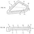
- FIG. 1A and FIG. 1B show a laminated glass with a resin frame.
- FIG. 1A is a front perspective view
- FIG. 1B is a sectional view taken on line A-A in FIG. 1A .
- An example of the laminated glass with a resin frame will be described with reference to FIG. 1A and FIG. 1B .
- a laminated glass 1 with a resin frame is an example which is, for example, chiefly attached to a triangular window for a rear door of a vehicle such as a car.
- the laminated glass 1 with a resin frame has a substantially triangular shape in a front view.
- the laminated glass 1 with a resin frame includes a laminated glass 10, and a resin frame 20 integrally formed in a peripheral portion of the laminated glass 10.
- the triangular window for the rear door is merely an example. The embodiment is not limited to such an application.
- the resin frame 20 is provided in at least one surface of the laminated glass 10 to meet a demand to make a body of a vehicle (particularly a luxury car or the like), the laminated glass (window glass) 10 and the resin frame 20 flush with one another.
- the laminated glass 10 has a first glass plate 11, a second glass plate 12, and an intermediate layer 13 disposed between the first glass plate 11 and the second glass plate 12.
- a surface of the first glass plate 11 is defined as a first surface 11a
- a surface of the second glass plate 12 on the opposite side to the first surface 11a is defined as a second surface 12a
- an outer periphery of the laminated glass 10 is defined as an end face 10a
- a part where the end face 10a and the second surface 12a abut on each other is defined as a boundary ridge line 14
- a region from the boundary ridge line 14 to a slightly inner part on the second surface 12a is defined as an outer peripheral region 15.
- the resin frame 20 is formed to continuously cover the end face 10a of the laminated glass 10 and a part of the first surface 11a near the end face 10a.
- the laminated glass 10 is manufactured in a known float process.
- a molten glass material is launched on molten metal such as tin, and a plate glass with uniform thickness and uniform plate width is molded by an exact temperature operation.
- An example of a composition of the first glass plate 11 and the second glass plate 12 for use in the embodiment includes a glass composition containing, as represented by mole percentage based on oxides, from 50 to 80% of SiO 2 , from 0 to 10% of B 2 O 3 , from 0.1 to 25% of Al 2 O 3 , from 3 to 30% of Li 2 O+Na 2 O+K 2 O, from 0 to 25% of MgO, from 0 to 25% of CaO, from 0 to 5% of SrO, from 0 to 5% of BaO, from 0 to 5% of ZrO 2 , and from 0 to 5% of SnO 2 .
- the composition is not limited to the example especially.
- the intermediate layer 13 may have a composition which is in general use in a conventional laminated glass for a vehicle.
- a composition which is in general use in a conventional laminated glass for a vehicle.
- PVB polyvinylbutyral
- EVA ethylene-vinyl acetate
- Use may be made of a thermosetting resin which is liquid before heating.
- the intermediate layer 13 may be in a liquid state or the like before the first glass plate 11 and the second glass plate 12 are bonded to each other, so long as the intermediate layer 13 is in a layer state after the laminated glass 10 is configured.
- FIG. 2A to FIG. 2C show an example of a first embodiment of the method for producing a laminated glass with a resin frame.
- FIG. 2A is a front perspective view
- FIG. 2B is a sectional view taken on line B-B in FIG.2A
- FIG. 2C is a front perspective view showing the laminated glass 1 with a resin frame.
- Example 1 of the laminated glass 1 with a resin frame includes a first embodiment and a second embodiment described later.
- a resin is molded on the second surface 12a of the second glass plate 12 at the same time as the resin frame 20 is integrally formed on the laminated glass 10.
- the resin frame 20 is defined as a first molding element 20a
- the resin to be molded on the second surface 12a is defined as a second molding element 21.
- the first molding element 20a and the second molding element 21 are concurrently molded from a plurality of gates 30.
- FIG. 2A resin flows of the first molding element 20a and the second molding element 21 are illustrated by allows.
- the gates 30 may be provided on the first surface side or the side surface side.
- Molding is performed in the following procedure.
- the removal trace 22 is a surface having a different texture from the surface of the resin frame 20 molded normally. Specifically, it is desired that a surface roughness in the removal trace 22 is at least 1.5 times or more preferably at least twice as high as a surface roughness in the surface of the resin frame 20 molded normally.
- the surface roughness is measured by a surface roughness tester (SURFCOM 120A, manufactured by Tokyo Seimitsu Co., Ltd). When the surface roughness was measured actually, a surface roughness Ra in the surface of the resin frame 20 was 0.64 ⁇ m, while a surface roughness Ra in a part of the removal trace 22 was 1.32 ⁇ m. Thus, there appeared a difference in texture.
- the removal trace 22 can be used as various marks.
- a robot or a worker can determine a direction or position of the laminated glass 10 based on a position of the removal trace 22.
- the phrase "on the same plane as the second surface” may allow some displacement between the second surface 12a and a surface where the removal trace 22 is formed, as long as an effect of the removal trace 22 is not lost.
- the second molding element 21 formed on the resin frame 20 when the second molding element 21 formed on the resin frame 20 is removed, the second molding element 21 may be left behind to protrude from the same plane as the second surface, as long as the second surface is not covered with the second molding element 21.
- the removal trace 22 may be a surface perpendicular to the second surface. In this manner, a part of the second molding element 21 and/or the removal trace 22 can be also used as an engagement part for installation for a vehicle body 50.
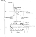
- FIG. 3 shows schematic views for explaining an opposing force to be applied and an outer peripheral region.
- the graph (a) of FIG. 3 is a graph of an integrated value of tensile stress in a plate thickness direction in a single glass plate constituting the laminated glass 10.
- the graph (b) of FIG. 3 shows a relationship between the laminated glass 1 with a resin frame and the graph. The opposing force to be applied will be described with reference to FIG. 3 .
- edge compression (E/C) (compression stress) stays behind within a predetermined distance from an end face of a glass plate constituting the laminated glass 10 because cooling during molding starts at an edge thereof.
- inner tension (I/T) (tensile stress) stays behind in a region inside the glass plate due to reaction of the E/C. Therefore, in the laminated glass 10 in which such two glass plates have been laminated, it is preferable that a peak position of the I/T(typically 10 to 20 mm from the end face of the glass plate) is within the outer peripheral region 15. The laminated glass 10 may be easily damaged at the peak position of I/T.
- an opposing force applying position P1 which is a position where an opposing force is applied to the second surface 12a of the laminated glass 10 is preferably located inside a position within the second surface, the position having a peak position of inner tension in a glass plate including the second surface of the laminated glass. That is, the opposing force applying position P1 is preferably located at least 20 mm inside from the end face of the laminated glass 10 within the second surface.
- an entire region of the opposing force applying position P1 on the second surface is located outside an innermost position P2 of the resin material within a surface on the first surface 11a side.
- a part of a region of the opposing force applying position P1 on the second surface may be located inside an innermost position P2 of the resin material within a surface on the first surface 11 a side. Due to this configuration, the opposing force applying position can be kept away from the peak position of the I/T. Thus, it is possible to apply the opposing force while reducing damage.
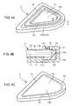
- FIG. 4A to FIG.4C show an example of a second embodiment of the method for producing the laminated glass 1 with a resin frame.
- FIG. 4A is a front perspective view during molding.
- FIG. 4B is a sectional view taken on line C-C in FIG. 4A.
- FIG. 4C is a front perspective view after the molding.
- the second embodiment of the method for producing the laminated glass 1 with a resin frame will be described with reference to FIG. 4A to FIG. 4C .
- the removal step (5) in the first embodiment is omitted.
- Other steps are similar to those in the first embodiment.
- the second molding element 21 is formed on a position inside the end face 10a of the laminated glass 10 and at a distance from the end face 10a.
- the cavity 41 of the shaping mold 40 abuts on the second surface 12a near the end face 10a to prevent the resin material for the resin frame 20 as a first molding element from getting over the end face 10a and reaching the second surface 12a.
- a resin material for the second molding element 21 may be the same as or different from the resin material forming the resin frame 20. Fluid or liquid such as water may be used. Thus, it is possible to extend a range of choices as the material for the second molding element 21.
- the second molding element 21 can be separated easily from the second surface 12a after solidification. Therefore, the removal step (5) of cutting the second molding element 21 from the resin frame 20 in the first embodiment is not required. Since the removal step (5) can be omitted, it is possible to reduce the cost or shorten the manufacturing time.
- FIG. 5A to FIG. 5C show Example 2 of the laminated glass 1 with a resin frame.
- FIG. 5A is a front perspective view during molding.
- FIG. 5B is a sectional view taken on line D-D in FIG. 5A.
- FIG. 5C is a back perspective view after the molding.
- the resin frame 20 in the laminated glass 1 with a resin frame according to the first embodiment and the second embodiment has been described as Example 1, in which the resin frame 20 has a form covering the first surface 11a and the end face 10a.
- the resin frame 20 may be formed only on the first surface 11a (Example 2) as shown in FIG. 5A to FIG. 5C .
- the production method in Example 2 is the same as that in the first embodiment or the second embodiment, except that the resin frame 20 is formed only on the first surface 11a.
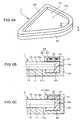
- FIG. 6B A third embodiment ( FIG. 6B ) and a fourth embodiment ( FIG. 6C ) of the method for producing the laminated glass 1 with a resin frame will be described with reference to FIG. 6A to FIG. 6C .
- the production method according to the fourth embodiment is similar to that according to the third embodiment, except that the opposing force applying member 25 includes only an elastic body 27 such as rubber (see FIG. 6C ).
- the elastic body 27 absorbs pressure applied to the opposing force applying member 25.
- the elastic modulus of the elastic body 27 is higher than that of the resin material and lower than that of a material of the shaping mold.
- the third embodiment and the fourth embodiment have been described along Example 1 of the laminated glass 1 with a resin frame, these embodiments can be described along Example 2 in a similar way.
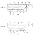
- FIG. 7A and FIG. 7B are sectional views each showing a state in which the laminated glass 1 with a resin frame has been attached to a vehicle body 50.
- FIG. 7A shows a state where the laminated glass 1 with a resin frame according to Example 1 has been attached.
- FIG. 7B shows a state where the laminated glass 1 with a resin frame according to Example 2 has been attached.
- Example 1 the second surface 12a of the laminated glass 1 with a resin frame, the resin frame 20, and the vehicle body 50 are arranged substantially on the same plane.
- Example 2 the second surface 12a of the laminated glass 1 with a resin frame, and the vehicle body 50 are arranged substantially on the same plane.
- the state where the laminated glass 1 with a resin frame is arranged can be changed suitably in accordance with its application.
- a section shown in FIG. 7A or FIG. 7B does not have to be formed in a periphery of the laminated glass 1 with a resin frame. That is, a part of a peripheral portion of the laminated glass 1 with a resin frame may have configuration covering the first surface 11 a, the second surface 12a and the end face 10a with the vehicle body.
- the removal trace 22 may be provided in a part which is covered with the vehicle body. In addition, the removal trace 22 may be also used as a mark or an engagement part when the laminated glass 1 with a resin frame is installed on the vehicle body 50.
- the resin material is injected from the first surface 11 a side of the laminated glass 10 in the injection step (2) in the description of the embodiments above, it may be understood that the resin material is injected from the first surface 11 a side of the laminated glass 10 or the end face 10a side of the laminated glass 10 because the first surface 11 a and the end face 10a are continuous to each other.
- a laminated glass with a resin frame according to the present invention is suitably used for a window or the like of a vehicle (particularly a luxury vehicle) in which a body, the laminated glass and the resin frame are made flush with one another from a point of view of design.
Landscapes
- Engineering & Computer Science (AREA)
- Mechanical Engineering (AREA)
- Manufacturing & Machinery (AREA)
- Injection Moulding Of Plastics Or The Like (AREA)
- Moulds For Moulding Plastics Or The Like (AREA)
- Laminated Bodies (AREA)
Abstract
Description
- The present invention relates to a method for producing a laminated glass with a resin frame for use in a window of a vehicle or the like, and a laminated glass with a resin frame.
- It has been known that a resin frame is formed on a peripheral portion of a laminated glass (see Patent Literature 1).
-
Patent Literature 1 discloses a method for producing a glass with a frame in which a ratio (w1+w2+w3)/w4 of a total w1+w2+w3 of a width w1 of a cavity for a frame in an interior-side glass surface, a width w2 of a communication hole and a width w3 of an auxiliary cavity to a width w4 of a cavity for a frame to be formed in an exterior-side glass surface is from 0.5 to 1.5. In this method, a load applied to a peripheral portion of a plate glass during injection molding can be reduced and the plate glass can be prevented from being damaged when a frame is integrally formed on the plate glass by injection molding. - Patent Literature 1:
JP-A-2009-269381 - In
Patent Literature 1, a frame is formed on an end face of a glass and peripheral portions of opposite surfaces of a glass. However, in recent years, it has been required from a point of view of design that a resin frame is provided in only one surface (for example, an indoor side of a vehicle) of a glass or only one surface and an end face of the glass. In this case, it can be considered that a surface of a mold is configured in contact with a glass surface (referred to as a second surface) where a frame will not be provided, so that no cavity can be formed in the second surface. However, it is physically (due to limited accuracy in machining) difficult to form the mold so that a surface of the mold can contact with the second surface with no gap. Therefore, some gap is always formed between the surface of the mold and the second surface. As a result, there is a problem that, due to a force applied to a peripheral portion of a glass when a resin is injected, chipping or the like may occur in the glass. - The present invention provides a method for producing a laminated glass with a resin frame, and a laminated glass with a resin frame, in which occurrence of chipping or the like in the laminated glass is suppressed.
- A method for producing a laminated glass with a resin frame according to the present invention includes a disposing step of disposing a laminated glass inside a shaping mold in which a cavity into which a resin material for a resin frame is injected is formed, an injection step of injecting the resin material into the cavity from a first surface side of the laminated glass or an end face side of the laminated glass, a blocking step of blocking a flow of the resin material in at least a part of a peripheral portion of the laminated glass to prevent the resin material from reaching an outer peripheral region on a second surface opposite to the first surface and an opposing force applying step of applying an opposing force from an opposing force applying position on the second surface and inside of the outer peripheral region of the laminated glass, wherein the opposing force applies to suppress pressure applied to the laminated glass in the injection step.
- A laminated glass with a resin frame according to the present invention includes a laminated glass including a first glass plate, a second glass plate and an intermediate layer disposed between the first glass plate and the second glass plate, and a resin frame placed on at least a part of an outer peripheral portion of the laminated glass. The laminated glass has a first surface, and a second surface opposite to the first surface. The resin frame has a removal trace on the same plane as the second surface.
- According to the present invention, pressure which is applied from a first surface side to a second surface side of a laminated glass during molding is suppressed in an injection step, to thereby prevent chipping or the like in the laminated glass.
-
FIG. 1A and FIG. 1B show an example of a laminated glass with a resin frame according to the present invention.FIG. 1A is a front perspective view andFIG. 1B is a sectional view taken on line A-A inFIG. 1A . -
FIG. 2A to FIG. 2C show an example of a first embodiment of a method for producing the laminated glass with a resin frame according to the present invention.FIG. 2A is a front perspective view during molding,FIG. 2B is a sectional view taken on line B-B inFIG.2A, and FIG. 2C is a front perspective view after the molding. -
FIG. 3 shows schematic views for explaining an opposing force to be applied during a production process and an outer peripheral region according to the present invention. The graph (a) ofFIG. 3 is a graph of tensile stress, and the graph (b) ofFIG. 3 is a view showing a relationship between the laminated glass with a resin frame and the graph (a) inFIG. 3 . -
FIG.4A to FIG. 4C show an example of a second embodiment of a method for producing the laminated glass with a resin frame according to the present invention.FIG. 4A is a front perspective view during molding,FIG. 4B is a sectional view taken on line C-C inFIG. 4A, and FIG. 4C is a front perspective view after the molding. -
FIG. 5A to FIG. 5C show an example of the second embodiment of the method for producing the laminated glass with a resin frame according to the present invention.FIG. 5A is a front perspective view during molding,FIG. 5B is a sectional view taken on line D-D inFIG. 5B, and FIG. 5C is a back perspective view after the molding. -
FIG. 6A to FIG. 6C show examples of a third embodiment and fourth embodiment according to the present invention.FIG. 6A is a front perspective view,FIG. 6B is a sectional view taken on line E-E inFIG. 6A according to the third embodiment, andFIG. 6C is a sectional view taken on line E-E inFIG. 6A according to the fourth embodiment. -
FIG. 7A and FIG. 7B show sectional views each showing a state in which a laminated glass with a resin frame according to the present invention has been attached to a body of a vehicle.FIG. 7A is a view showing an attachment in Example 1, andFIG. 7B is a view showing an attachment in Example 2. - Specific embodiments of a laminated glass with a resin frame according to the present invention will be described below in detail with reference to the drawings.
-
FIG. 1A and FIG. 1B show a laminated glass with a resin frame.FIG. 1A is a front perspective view, andFIG. 1B is a sectional view taken on line A-A inFIG. 1A . An example of the laminated glass with a resin frame will be described with reference toFIG. 1A and FIG. 1B . - In the embodiment, a
laminated glass 1 with a resin frame is an example which is, for example, chiefly attached to a triangular window for a rear door of a vehicle such as a car. Thus, thelaminated glass 1 with a resin frame has a substantially triangular shape in a front view. Thelaminated glass 1 with a resin frame includes alaminated glass 10, and aresin frame 20 integrally formed in a peripheral portion of thelaminated glass 10. Incidentally, the triangular window for the rear door is merely an example. The embodiment is not limited to such an application. In addition, in thelaminated glass 1 with a resin frame according to the embodiment, from a point of view of more excellent design, theresin frame 20 is provided in at least one surface of thelaminated glass 10 to meet a demand to make a body of a vehicle (particularly a luxury car or the like), the laminated glass (window glass) 10 and theresin frame 20 flush with one another. - The
laminated glass 10 has afirst glass plate 11, asecond glass plate 12, and anintermediate layer 13 disposed between thefirst glass plate 11 and thesecond glass plate 12. A surface of thefirst glass plate 11 is defined as afirst surface 11a, a surface of thesecond glass plate 12 on the opposite side to thefirst surface 11a is defined as asecond surface 12a, an outer periphery of thelaminated glass 10 is defined as anend face 10a, a part where theend face 10a and thesecond surface 12a abut on each other is defined as aboundary ridge line 14, and a region from theboundary ridge line 14 to a slightly inner part on thesecond surface 12a is defined as an outerperipheral region 15. In the laminated glass with a resin frame according to the embodiment, theresin frame 20 is formed to continuously cover theend face 10a of thelaminated glass 10 and a part of thefirst surface 11a near theend face 10a. - The
laminated glass 10 is manufactured in a known float process. In the float process, a molten glass material is launched on molten metal such as tin, and a plate glass with uniform thickness and uniform plate width is molded by an exact temperature operation. - An example of a composition of the
first glass plate 11 and thesecond glass plate 12 for use in the embodiment includes a glass composition containing, as represented by mole percentage based on oxides, from 50 to 80% of SiO2, from 0 to 10% of B2O3, from 0.1 to 25% of Al2O3, from 3 to 30% of Li2O+Na2O+K2O, from 0 to 25% of MgO, from 0 to 25% of CaO, from 0 to 5% of SrO, from 0 to 5% of BaO, from 0 to 5% of ZrO2, and from 0 to 5% of SnO2. However, the composition is not limited to the example especially. - The
intermediate layer 13 may have a composition which is in general use in a conventional laminated glass for a vehicle. For example, polyvinylbutyral (PVB), ethylene-vinyl acetate (EVA), etc. may be used. Use may be made of a thermosetting resin which is liquid before heating. Namely, theintermediate layer 13 may be in a liquid state or the like before thefirst glass plate 11 and thesecond glass plate 12 are bonded to each other, so long as theintermediate layer 13 is in a layer state after thelaminated glass 10 is configured. - Each embodiment of the method for producing the
laminated glass 1 with a resin frame will be described in detail with reference toFIG. 2A to FIG. 6C .FIG. 2A to FIG. 2C show an example of a first embodiment of the method for producing a laminated glass with a resin frame.FIG. 2A is a front perspective view,FIG. 2B is a sectional view taken on line B-B inFIG.2A, and FIG. 2C is a front perspective view showing thelaminated glass 1 with a resin frame. Incidentally, Example 1 of thelaminated glass 1 with a resin frame includes a first embodiment and a second embodiment described later. - In the first embodiment, a resin is molded on the
second surface 12a of thesecond glass plate 12 at the same time as theresin frame 20 is integrally formed on thelaminated glass 10. Theresin frame 20 is defined as afirst molding element 20a, and the resin to be molded on thesecond surface 12a is defined as asecond molding element 21. Thefirst molding element 20a and thesecond molding element 21 are concurrently molded from a plurality ofgates 30. InFIG. 2A , resin flows of thefirst molding element 20a and thesecond molding element 21 are illustrated by allows. Thegates 30 may be provided on the first surface side or the side surface side. - Molding is performed in the following procedure.
- (1) Disposing Step: First, the
laminated glass 10 is disposed inside a shaping metal mold (referred to as a shaping mold) 40. Acavity 41 having a concave shape for forming theresin frame 20 is formed in the shapingmold 40. - (2) Injection Step: Next, a resin material is injected from the
first surface 11a side of thelaminated glass 10 in thecavity 41 through thegates 30, so as to form theresin frame 20 covering a peripheral portion of thefirst surface 11a near theend face 10a. That is, theresin frame 20 is formed to cover thefirst surface 11a and theend face 10a continuously. - (3) Blocking Step: In at least a part of the peripheral portion of the
laminated glass 10, a flow of the resin material is blocked to prevent the resin material from reaching an outerperipheral region 15 on asecond surface 12a opposite to thefirst surface 11 a. In the first embodiment, the flow of the resin material is blocked by the shaping mold in contact with the outerperipheral region 15. Here, the outerperipheral region 15 designates a region with a fixed width within the second surface including theboundary ridge line 14 where theend face 10a and thesecond surface 12a abut on each other. Incidentally, the flow of the resin material may be blocked in a periphery of thelaminated glass 10 to be prevented from reaching the outerperipheral region 15 on thesecond surface 12a opposite to thefirst surface 11a. - (4) Opposing force Applying Step: In the first embodiment, the
second molding element 21 is formed at the same time as the injection step. Thesecond molding element 21 is formed on a position (hereinafter also referred to as an opposing force applying position) inside the outerperipheral region 15 of thelaminated glass 10, thereby applying an opposing force which applies to suppress pressure applied to thelaminated glass 10 in the injection step (2).
Due to this step, a force is prevented from applying to the peripheral portion of thelaminated glass 10, thereby suppressing occurrence of chipping or the like in thelaminated glass 10. In the background art, when there is a slight gap between thesecond surface 12a of thesecond glass plate 12 and thecavity 41 of the shapingmold 40, there is a risk that thelaminated glass 10 may be damaged due to molding pressure for forming theresin frame 20. However, due to this step, occurrence of a gap is suppressed and damage is less likely to occur. In addition, a so-called nick, that is, chipping like a semi-elliptic shape is apt to occur particularly in a part inside the second surface from theboundary ridge line 14 in the background art. Such a nick can be suppressed.
In addition, when the resin material is injected from thefirst surface 11a side, thelaminated glass 10 is hardly bent like a cantilever from the first surface to the second surface. Therefore, a load is hardly applied to the peripheral portion and damage can be suppressed.
In addition, in the embodiment ofFIG. 2A to FIG. 2C , a part of the resin material injected passes through the outer peripheral region on thesecond surface 12a and reaches the opposing force applying position of thesecond surface 12a. Thus, the opposing force is applied to the part of the resin material. The part of the resin material is cooled as it is. When a resin material similar to that of the first surface is used for the second surface, chipping or the like in thelaminated glass 1 with a resin frame is prevented during cooling of the shapingmold 40. This can be considered that a difference in stress between front and back surfaces of thelaminated glass 1 with a resin frame can be reduced due to a difference in thermal shrinkage between glasses and the resin material during the cooling.
In addition, the embodiment ofFIG. 2A to FIG. 2C includes the following step. - (5) Removal Step (Cutting Step): After the
laminated glass 1 with a resin frame is extracted from the shapingmold 40, thesecond molding element 21 is removed. In the first embodiment, thesecond molding element 21 formed on theresin frame 20 is cut on the same plane as thesecond surface 12a. Thus, aremoval trace 22 is left behind on theresin frame 20. - The
removal trace 22 is a surface having a different texture from the surface of theresin frame 20 molded normally. Specifically, it is desired that a surface roughness in theremoval trace 22 is at least 1.5 times or more preferably at least twice as high as a surface roughness in the surface of theresin frame 20 molded normally. The surface roughness is measured by a surface roughness tester (SURFCOM 120A, manufactured by Tokyo Seimitsu Co., Ltd). When the surface roughness was measured actually, a surface roughness Ra in the surface of theresin frame 20 was 0.64 µm, while a surface roughness Ra in a part of theremoval trace 22 was 1.32 µm. Thus, there appeared a difference in texture. - As a result, the
removal trace 22 can be used as various marks. For example, when a glass is installed, a robot or a worker can determine a direction or position of thelaminated glass 10 based on a position of theremoval trace 22. Incidentally, the phrase "on the same plane as the second surface" may allow some displacement between thesecond surface 12a and a surface where theremoval trace 22 is formed, as long as an effect of theremoval trace 22 is not lost. - In addition, when the
second molding element 21 formed on theresin frame 20 is removed, thesecond molding element 21 may be left behind to protrude from the same plane as the second surface, as long as the second surface is not covered with thesecond molding element 21. On that occasion, theremoval trace 22 may be a surface perpendicular to the second surface. In this manner, a part of thesecond molding element 21 and/or theremoval trace 22 can be also used as an engagement part for installation for avehicle body 50. -
FIG. 3 shows schematic views for explaining an opposing force to be applied and an outer peripheral region. The graph (a) ofFIG. 3 is a graph of an integrated value of tensile stress in a plate thickness direction in a single glass plate constituting thelaminated glass 10. The graph (b) ofFIG. 3 shows a relationship between thelaminated glass 1 with a resin frame and the graph. The opposing force to be applied will be described with reference toFIG. 3 . - As shown in the graph (a) in
FIG. 3 , edge compression (E/C) (compression stress) stays behind within a predetermined distance from an end face of a glass plate constituting thelaminated glass 10 because cooling during molding starts at an edge thereof. Further, inner tension (I/T) (tensile stress) stays behind in a region inside the glass plate due to reaction of the E/C. Therefore, in thelaminated glass 10 in which such two glass plates have been laminated, it is preferable that a peak position of the I/T(typically 10 to 20 mm from the end face of the glass plate) is within the outerperipheral region 15. Thelaminated glass 10 may be easily damaged at the peak position of I/T. Therefore, when the peak position of the I/T is located in a region where the resin material is not provided, damage can be reduced. Thus, as shown in the graph (b) ofFIG. 3 , an opposing force applying position P1 which is a position where an opposing force is applied to thesecond surface 12a of thelaminated glass 10 is preferably located inside a position within the second surface, the position having a peak position of inner tension in a glass plate including the second surface of the laminated glass. That is, the opposing force applying position P1 is preferably located at least 20 mm inside from the end face of thelaminated glass 10 within the second surface. Thus, it is possible to reduce such a fear that damage may occur due to the opposing force applied to the peak position of the I/T. - Incidentally, in
FIG. 2A to FIG. 2C , an entire region of the opposing force applying position P1 on the second surface is located outside an innermost position P2 of the resin material within a surface on thefirst surface 11a side. However, as shown in the graph (b) ofFIG. 3 , a part of a region of the opposing force applying position P1 on the second surface may be located inside an innermost position P2 of the resin material within a surface on thefirst surface 11 a side. Due to this configuration, the opposing force applying position can be kept away from the peak position of the I/T. Thus, it is possible to apply the opposing force while reducing damage. -
FIG. 4A to FIG.4C show an example of a second embodiment of the method for producing thelaminated glass 1 with a resin frame.FIG. 4A is a front perspective view during molding.FIG. 4B is a sectional view taken on line C-C inFIG. 4A. FIG. 4C is a front perspective view after the molding. The second embodiment of the method for producing thelaminated glass 1 with a resin frame will be described with reference toFIG. 4A to FIG. 4C . - In the second embodiment, the removal step (5) in the first embodiment is omitted. Other steps are similar to those in the first embodiment. In the second embodiment, the
second molding element 21 is formed on a position inside theend face 10a of thelaminated glass 10 and at a distance from theend face 10a. In the injection step (2), thecavity 41 of the shapingmold 40 abuts on thesecond surface 12a near theend face 10a to prevent the resin material for theresin frame 20 as a first molding element from getting over theend face 10a and reaching thesecond surface 12a. - Various materials may be used for the
second molding element 21 as long as an opposing force can be applied. A resin material for thesecond molding element 21 may be the same as or different from the resin material forming theresin frame 20. Fluid or liquid such as water may be used. Thus, it is possible to extend a range of choices as the material for thesecond molding element 21. In addition, thesecond molding element 21 can be separated easily from thesecond surface 12a after solidification. Therefore, the removal step (5) of cutting thesecond molding element 21 from theresin frame 20 in the first embodiment is not required. Since the removal step (5) can be omitted, it is possible to reduce the cost or shorten the manufacturing time. -
FIG. 5A to FIG. 5C show Example 2 of thelaminated glass 1 with a resin frame.FIG. 5A is a front perspective view during molding.FIG. 5B is a sectional view taken on line D-D inFIG. 5A. FIG. 5C is a back perspective view after the molding. Theresin frame 20 in thelaminated glass 1 with a resin frame according to the first embodiment and the second embodiment has been described as Example 1, in which theresin frame 20 has a form covering thefirst surface 11a and theend face 10a. However, theresin frame 20 may be formed only on thefirst surface 11a (Example 2) as shown inFIG. 5A to FIG. 5C . In addition, the production method in Example 2 is the same as that in the first embodiment or the second embodiment, except that theresin frame 20 is formed only on thefirst surface 11a. - A third embodiment (
FIG. 6B ) and a fourth embodiment (FIG. 6C ) of the method for producing thelaminated glass 1 with a resin frame will be described with reference toFIG. 6A to FIG. 6C . - The production method according to the third embodiment will be described below.
- (1) Disposing Step: The
laminated glass 10 is disposed inside the shapingmold 40. Thecavity 41 of the shapingmold 40 is formed to enclose theend face 10a of thelaminated glass 10. After thelaminated glass 10 is disposed inside the shapingmold 40, an opposingforce applying member 25 is disposed on a periphery of thesecond surface 12a near theend face 10a and at least on the outerperipheral region 15. The opposingforce applying member 25 also serves for preventing the resin material forming theresin frame 20 from getting over theend face 10a and reaching thesecond surface 12a during molding.
In the third embodiment, the opposingforce applying member 25 includes arigid body 26 having a predetermined rigidity, and anelastic body 27 such as a spring capable of absorbing pressure applied to the rigid body 26 (seeFIG. 6B ). - (2) Injection Step: Next, a resin material is injected from the
first surface 11a side of thelaminated glass 10 in thecavity 41 through thegates 30, so as to form theresin frame 20 covering a peripheral portion of thefirst surface 11 a near theend face 10a. That is, theresin frame 20 is formed to cover thefirst surface 11a and theend face 10a continuously. In the injection step (2), the blocking step (3) and the opposing force applying step (4) are performed concurrently. - (3) Blocking Step: In at least a part of the peripheral portion of the
laminated glass 10, a flow of the resin material is blocked to prevent the resin material from reaching an outerperipheral region 15 on asecond surface 12a opposite to thefirst surface 11 a. In the third embodiment, the flow of the resin material is blocked by the opposingforce applying member 25 in contact with the outerperipheral region 15. - (4) Opposing force Applying Step: The opposing
force applying member 25 applies an opposing force from thesecond surface 12a to suppress pressure occurring in a process in which theresin frame 20 is formed. In this step, chipping of thelaminated glass 10 is prevented. Simultaneously, the opposingforce applying member 25 prevents the resin material forming theresin frame 20 from reaching thesecond surface 12a. That is, the opposingforce applying member 25 is disposed in tight contact with thesecond surface 12a in thecavity 41 on thesecond surface 12a side and so as to protrude from theend face 10a with the same width as a width with which theresin frame 20 protrudes from theend face 10a. - The production method according to the fourth embodiment is similar to that according to the third embodiment, except that the opposing
force applying member 25 includes only anelastic body 27 such as rubber (seeFIG. 6C ). In the injection step (2) (opposing force applying step (4)), theelastic body 27 absorbs pressure applied to the opposingforce applying member 25. Here, the elastic modulus of theelastic body 27 is higher than that of the resin material and lower than that of a material of the shaping mold. In addition, although the third embodiment and the fourth embodiment have been described along Example 1 of thelaminated glass 1 with a resin frame, these embodiments can be described along Example 2 in a similar way. -
FIG. 7A and FIG. 7B are sectional views each showing a state in which thelaminated glass 1 with a resin frame has been attached to avehicle body 50.FIG. 7A shows a state where thelaminated glass 1 with a resin frame according to Example 1 has been attached.FIG. 7B shows a state where thelaminated glass 1 with a resin frame according to Example 2 has been attached. In Example 1, thesecond surface 12a of thelaminated glass 1 with a resin frame, theresin frame 20, and thevehicle body 50 are arranged substantially on the same plane. In Example 2, thesecond surface 12a of thelaminated glass 1 with a resin frame, and thevehicle body 50 are arranged substantially on the same plane. Thus, superior design can be obtained. The state where thelaminated glass 1 with a resin frame is arranged can be changed suitably in accordance with its application. - Incidentally, when the
laminated glass 1 with a resin frame according to Example 1 or 2 of the present invention is attached to thevehicle body 50, a section shown inFIG. 7A or FIG. 7B does not have to be formed in a periphery of thelaminated glass 1 with a resin frame. That is, a part of a peripheral portion of thelaminated glass 1 with a resin frame may have configuration covering thefirst surface 11 a, thesecond surface 12a and theend face 10a with the vehicle body. Theremoval trace 22 may be provided in a part which is covered with the vehicle body. In addition, theremoval trace 22 may be also used as a mark or an engagement part when thelaminated glass 1 with a resin frame is installed on thevehicle body 50. - Although the resin material is injected from the
first surface 11 a side of thelaminated glass 10 in the injection step (2) in the description of the embodiments above, it may be understood that the resin material is injected from thefirst surface 11 a side of thelaminated glass 10 or theend face 10a side of thelaminated glass 10 because thefirst surface 11 a and theend face 10a are continuous to each other. - The present invention should not be construed as being limited to the embodiments described above, and modifications, improvements, etc. can be suitably made therein. Materials, shapes, dimensions, numerical values, configurations, numbers, positions, etc. of each constituent element in each of the embodiments described above are at will and not limited so long as the present invention can be achieved.
- A laminated glass with a resin frame according to the present invention is suitably used for a window or the like of a vehicle (particularly a luxury vehicle) in which a body, the laminated glass and the resin frame are made flush with one another from a point of view of design.
-
- 1
- laminated glass with resin frame
- 10
- laminated glass (window glass)
- 10a
- end face
- 11
- first glass plate
- 11a
- first surface
- 12
- second glass plate
- 12a
- second surface
- 13
- intermediate layer
- 14
- boundary ridge line
- 15
- outer peripheral region
- 20
- resin frame
- 20a
- first molding element
- 21
- second molding element
- 22
- removal trace
- 25
- opposing force applying member
- 26
- rigid body
- 27
- elastic body
- 30
- gates
- 40
- shaping mold (shaping metal mold)
- 41
- cavity
- 50
- body
Claims (13)
- A method for producing a laminated glass with a resin frame, comprising:a disposing step of disposing a laminated glass inside a shaping mold in which a cavity into which a resin material for a resin frame is injected is formed;an injection step of injecting the resin material into the cavity from a first surface side of the laminated glass or an end face side of the laminated glass;a blocking step of blocking a flow of the resin material in at least a part of a peripheral portion of the laminated glass to prevent the resin material from reaching an outer peripheral region on a second surface opposite to the first surface; andan opposing force applying step of applying an opposing force from an opposing force applying position on the second surface and inside of the outer peripheral region of the laminated glass, wherein the opposing force applies to suppress pressure applied to the laminated glass in the injection step.
- The method for producing a laminated glass with a resin frame according to claim 1, wherein:a part of the resin material injected passes through the outer peripheral region on the second surface and reaches the opposing force applying position on the second surface, thereby applying the opposing force; andthe method further comprising:a removal step of removing the resin material on the second surface.
- The method for producing a laminated glass with a resin frame according to claim 1, wherein:the resin material injected from the first surface side or the end face side is prevented from reaching the second surface in a periphery of the laminated glass.
- The method for producing a laminated glass with a resin frame according to claim 3, wherein:the opposing force applying step is carried out by injecting a resin material from the second surface side toward the opposing force applying position, the resin material being the same as or different from the resin material in the injection step.
- The method for producing a laminated glass with a resin frame according to claim 3, wherein:an opposing force applying member is disposed on the opposing force applying position and on the outer peripheral region;the opposing force applying member blocks a flow of the resin material in the blocking step; andthe opposing force applying member applies the opposing force in the opposing force applying step.
- The method for producing a laminated glass with a resin frame according to claim 5, wherein:the opposing force applying member is an elastic body which can absorb pressure applied to the opposing force applying member in the injection step.
- The method for producing a laminated glass with a resin frame according to any one of claims 1 to 6, wherein:a peak position of inner tension in a glass plate including the second surface of the laminated glass is located within the outer peripheral region.
- The method for producing a laminated glass with a resin frame according to any one of claims 1 to 7, wherein:the opposing force applying position is located inside a position within the second surface, the position having a peak position of inner tension in a glass plate including the second surface of the laminated glass.
- The method for producing a laminated glass with a resin frame according to any one of claims 1 to 8, wherein:the opposing force applying position is located at least 20 mm inside from the end face of the laminated glass.
- The method for producing a laminated glass with a resin frame according to any one of claims 1 to 9, wherein:a part of the opposing force applying position on the second surface is located inside an innermost position of the resin material within a surface on the first surface side.
- The method for producing a laminated glass with a resin frame according to any one of claims 1 to 10, wherein:the resin material forms the resin frame covering the first surface and the end face continuously.
- A laminated glass with a resin frame, comprising:a laminated glass including a first glass plate, a second glass plate, and an intermediate layer disposed between the first glass plate and the second glass plate; anda resin frame placed on at least a part of an outer peripheral portion of the laminated glass; wherein:the laminated glass includes a first surface and a second surface opposite to the first surface; andthe resin frame includes a removal trace on the same plane as the second surface.
- The laminated glass with a resin frame according to claim 12, wherein a surface roughness of the removal trace is at least 1.5 times as high as a surface roughness of the resin frame.
Applications Claiming Priority (1)
| Application Number | Priority Date | Filing Date | Title |
|---|---|---|---|
| JP2016036083A JP6597390B2 (en) | 2016-02-26 | 2016-02-26 | Method for producing laminated glass with resin frame and laminated glass with resin frame |
Publications (2)
| Publication Number | Publication Date |
|---|---|
| EP3210741A1 true EP3210741A1 (en) | 2017-08-30 |
| EP3210741B1 EP3210741B1 (en) | 2020-04-01 |
Family
ID=58191207
Family Applications (1)
| Application Number | Title | Priority Date | Filing Date |
|---|---|---|---|
| EP17000300.8A Active EP3210741B1 (en) | 2016-02-26 | 2017-02-24 | Method for producing laminated glass with resin frame, and laminated glass with resin frame |
Country Status (4)
| Country | Link |
|---|---|
| US (1) | US10272603B2 (en) |
| EP (1) | EP3210741B1 (en) |
| JP (1) | JP6597390B2 (en) |
| CN (1) | CN107129163B (en) |
Cited By (2)
| Publication number | Priority date | Publication date | Assignee | Title |
|---|---|---|---|---|
| EP3501781A1 (en) * | 2017-12-22 | 2019-06-26 | AGC Glass Europe | Mold to overmold a plastic material to at least a portion of the periphery of a glazing panel |
| WO2019121354A1 (en) * | 2017-12-22 | 2019-06-27 | Agc Glass Europe | Mold to overmold a plastic material to at least a portion of the periphery of a glazing panel |
Families Citing this family (2)
| Publication number | Priority date | Publication date | Assignee | Title |
|---|---|---|---|---|
| CN106945493B (en) * | 2017-03-14 | 2019-10-18 | 福耀玻璃工业集团股份有限公司 | A wrapping assembly for vehicle window glass |
| WO2021024819A1 (en) * | 2019-08-08 | 2021-02-11 | Agc株式会社 | Method for manufacturing resin-framed glass plate |
Citations (3)
| Publication number | Priority date | Publication date | Assignee | Title |
|---|---|---|---|---|
| FR2600933A1 (en) * | 1986-07-04 | 1988-01-08 | Boussois Sa | Process for the manufacture of an article of glazing which includes a seal made of heat-meltable resin overmoulded around its periphery and article of glazing thus obtained |
| DE10021808A1 (en) * | 2000-05-04 | 2001-10-18 | Daimler Chrysler Ag | Injection molding tool, for injecting polymer profile around glass plate, e.g. sun roof window of vehicle |
| JP2009269381A (en) | 2008-05-12 | 2009-11-19 | Central Glass Co Ltd | Mold for injection molding of framed glass and method of manufacturing framed glass |
Family Cites Families (25)
| Publication number | Priority date | Publication date | Assignee | Title |
|---|---|---|---|---|
| FR801539A (en) * | 1936-02-05 | 1936-08-06 | Pilkington Brothers Ltd | Improvements in the manufacture of glass objects in combination with plastics |
| FR2546812B1 (en) * | 1983-05-30 | 1986-04-18 | Saint Gobain Vitrage | |
| JPS61138521U (en) * | 1985-02-16 | 1986-08-28 | ||
| US4762481A (en) * | 1985-11-01 | 1988-08-09 | Libbey-Owens-Ford Co. | Mold structure for producing a window assembly |
| US4662113A (en) * | 1985-11-01 | 1987-05-05 | Libbey-Owens-Ford Co. | Window assembly and method of making the same |
| US4688752A (en) * | 1986-04-25 | 1987-08-25 | Libbey-Owens-Ford Co. | Mold structure for producing an encapsulated window assembly |
| US4795667A (en) * | 1986-05-01 | 1989-01-03 | Libbey-Owens-Ford Co. | Vehicle window assembly having a retention shield and method and apparatus for producing same |
| JPS63162210A (en) * | 1986-12-26 | 1988-07-05 | Hashimoto Forming Co Ltd | Preparation of window |
| US4732553A (en) * | 1987-07-06 | 1988-03-22 | Libbey-Owens-Ford Co. | Seal construction for a mold structure for encapsulating glass with a gasket |
| US4915395A (en) * | 1987-08-21 | 1990-04-10 | Libbey-Owens-Ford Co. | Seal construction for a mold structure for encapsulating glass with a gasket |
| US4854599A (en) * | 1987-08-21 | 1989-08-08 | Libbey-Owens-Ford Co. | Seal construction for a mold structure for encapsulating glass with a gasket |
| EP0354481B1 (en) * | 1988-08-09 | 1995-11-29 | Asahi Glass Company Ltd. | Method of preparing window glass with a gasket and a shaping mold for preparing such window glass |
| JPH0536645Y2 (en) * | 1988-10-03 | 1993-09-16 | ||
| JP2687533B2 (en) * | 1989-01-06 | 1997-12-08 | 旭硝子株式会社 | Method for manufacturing window glass with gasket |
| JP2583693Y2 (en) * | 1993-05-28 | 1998-10-27 | 日本板硝子株式会社 | Injection molding machine for resin frame |
| US6461137B1 (en) * | 1996-08-02 | 2002-10-08 | Charles E. Ash | Molding apparatus for encapsulating a sheet of material |
| US6123535A (en) * | 1996-08-02 | 2000-09-26 | Libbey-Owens-Ford Co. | Molding apparatus for encapsulating a part |
| US5916600A (en) * | 1996-09-06 | 1999-06-29 | Donnelly Corporation | Mold assembly for holding a sheet of glass during molding |
| JP3594077B2 (en) * | 2000-09-25 | 2004-11-24 | 旭硝子株式会社 | Method for manufacturing window plate with mounting member |
| DE10154553B4 (en) * | 2001-11-07 | 2005-06-09 | Saint-Gobain Sekurit Deutschland Gmbh & Co. Kg | Method and device for producing a profile strand on a component |
| JP3862714B2 (en) * | 2003-07-15 | 2006-12-27 | 東海興業株式会社 | Window assembly manufacturing method and window plate |
| WO2008035736A1 (en) * | 2006-09-22 | 2008-03-27 | Nissha Printing Co., Ltd. | Housing case, method for manufacturing the housing case and glass insert forming die used in the method |
| EP2376269B1 (en) * | 2009-01-15 | 2018-08-29 | Pilkington Group Limited | Dynamic seal for molding process and method of using |
| EP2799201B1 (en) * | 2013-04-30 | 2015-11-18 | Webasto SE | Method and mould for producing a panel assembly |
| CN105992684B (en) * | 2013-12-27 | 2018-05-15 | 旭硝子株式会社 | The manufacture method and device of the integrally formed product of glass resin |
-
2016
- 2016-02-26 JP JP2016036083A patent/JP6597390B2/en active Active
-
2017
- 2017-02-23 US US15/440,486 patent/US10272603B2/en active Active
- 2017-02-24 EP EP17000300.8A patent/EP3210741B1/en active Active
- 2017-02-24 CN CN201710102624.8A patent/CN107129163B/en active Active
Patent Citations (3)
| Publication number | Priority date | Publication date | Assignee | Title |
|---|---|---|---|---|
| FR2600933A1 (en) * | 1986-07-04 | 1988-01-08 | Boussois Sa | Process for the manufacture of an article of glazing which includes a seal made of heat-meltable resin overmoulded around its periphery and article of glazing thus obtained |
| DE10021808A1 (en) * | 2000-05-04 | 2001-10-18 | Daimler Chrysler Ag | Injection molding tool, for injecting polymer profile around glass plate, e.g. sun roof window of vehicle |
| JP2009269381A (en) | 2008-05-12 | 2009-11-19 | Central Glass Co Ltd | Mold for injection molding of framed glass and method of manufacturing framed glass |
Cited By (2)
| Publication number | Priority date | Publication date | Assignee | Title |
|---|---|---|---|---|
| EP3501781A1 (en) * | 2017-12-22 | 2019-06-26 | AGC Glass Europe | Mold to overmold a plastic material to at least a portion of the periphery of a glazing panel |
| WO2019121354A1 (en) * | 2017-12-22 | 2019-06-27 | Agc Glass Europe | Mold to overmold a plastic material to at least a portion of the periphery of a glazing panel |
Also Published As
| Publication number | Publication date |
|---|---|
| US10272603B2 (en) | 2019-04-30 |
| JP6597390B2 (en) | 2019-10-30 |
| EP3210741B1 (en) | 2020-04-01 |
| CN107129163B (en) | 2021-06-01 |
| US20170246779A1 (en) | 2017-08-31 |
| JP2017149118A (en) | 2017-08-31 |
| CN107129163A (en) | 2017-09-05 |
Similar Documents
| Publication | Publication Date | Title |
|---|---|---|
| EP3210741B1 (en) | Method for producing laminated glass with resin frame, and laminated glass with resin frame | |
| JP7184051B2 (en) | Fixed window glass with resin frame and manufacturing method thereof | |
| TWI678341B (en) | Vehicle display device | |
| KR20080100831A (en) | Vehicle window glass holder and method for manufacturing vehicle window assembly using the same | |
| CN101454230A (en) | Method for producing a glass pane | |
| EP3486148B1 (en) | Pillar structure for a vehicle | |
| KR20190077337A (en) | Sliding glazing with internal protrusions | |
| CN118212849A (en) | Display device and method for manufacturing the same | |
| JP7511112B2 (en) | Glass plate with resin frame for vehicle windows | |
| US8312688B2 (en) | Glazing comprising a reinforcement element | |
| US12441087B2 (en) | Laminated glazing for a motor vehicle, particularly a side glazing | |
| US12246583B1 (en) | Reinforced window | |
| JP5136193B2 (en) | Mold for injection molding of glass with frame and method for producing glass with frame | |
| US20170165883A1 (en) | Glass encapsulation structure and injection molding device | |
| CN101102921B (en) | Airbag flap system and method for manufacturing airbag flap system | |
| KR101345133B1 (en) | Mold for vulcanization of tire | |
| CN111417571B (en) | Window glass and components including window glass | |
| JP7240427B2 (en) | glass plate module | |
| EP4509366A1 (en) | Sunroof glass assembly, vehicles, and luggage carrier | |
| KR20050068357A (en) | Structure for assembling a side window glass for bus | |
| JP2012188033A (en) | Attachment structure for window glass | |
| CN120156263B (en) | Window glass components and vehicles | |
| JP6467236B2 (en) | Fixture and glass plate structure | |
| CN115884891A (en) | Side sliding laminated glass windows with protected side chimes and side doors | |
| KR20250174656A (en) | Cover elements and packaging |
Legal Events
| Date | Code | Title | Description |
|---|---|---|---|
| PUAI | Public reference made under article 153(3) epc to a published international application that has entered the european phase |
Free format text: ORIGINAL CODE: 0009012 |
|
| STAA | Information on the status of an ep patent application or granted ep patent |
Free format text: STATUS: THE APPLICATION HAS BEEN PUBLISHED |
|
| AK | Designated contracting states |
Kind code of ref document: A1 Designated state(s): AL AT BE BG CH CY CZ DE DK EE ES FI FR GB GR HR HU IE IS IT LI LT LU LV MC MK MT NL NO PL PT RO RS SE SI SK SM TR |
|
| AX | Request for extension of the european patent |
Extension state: BA ME |
|
| STAA | Information on the status of an ep patent application or granted ep patent |
Free format text: STATUS: REQUEST FOR EXAMINATION WAS MADE |
|
| 17P | Request for examination filed |
Effective date: 20180222 |
|
| RBV | Designated contracting states (corrected) |
Designated state(s): AL AT BE BG CH CY CZ DE DK EE ES FI FR GB GR HR HU IE IS IT LI LT LU LV MC MK MT NL NO PL PT RO RS SE SI SK SM TR |
|
| RAP1 | Party data changed (applicant data changed or rights of an application transferred) |
Owner name: AGC INC. |
|
| GRAP | Despatch of communication of intention to grant a patent |
Free format text: ORIGINAL CODE: EPIDOSNIGR1 |
|
| STAA | Information on the status of an ep patent application or granted ep patent |
Free format text: STATUS: GRANT OF PATENT IS INTENDED |
|
| RIC1 | Information provided on ipc code assigned before grant |
Ipc: B29L 31/30 20060101ALN20190920BHEP Ipc: B32B 17/06 20060101ALI20190920BHEP Ipc: B32B 17/10 20060101ALI20190920BHEP Ipc: B29C 45/14 20060101AFI20190920BHEP Ipc: B29L 31/00 20060101ALN20190920BHEP |
|
| INTG | Intention to grant announced |
Effective date: 20191018 |
|
| RIC1 | Information provided on ipc code assigned before grant |
Ipc: B29C 45/14 20060101AFI20191007BHEP Ipc: B32B 17/10 20060101ALI20191007BHEP Ipc: B29L 31/30 20060101ALN20191007BHEP Ipc: B29L 31/00 20060101ALN20191007BHEP Ipc: B32B 17/06 20060101ALI20191007BHEP |
|
| RIN1 | Information on inventor provided before grant (corrected) |
Inventor name: OKUDA, JIRO |
|
| GRAS | Grant fee paid |
Free format text: ORIGINAL CODE: EPIDOSNIGR3 |
|
| GRAA | (expected) grant |
Free format text: ORIGINAL CODE: 0009210 |
|
| STAA | Information on the status of an ep patent application or granted ep patent |
Free format text: STATUS: THE PATENT HAS BEEN GRANTED |
|
| RIN1 | Information on inventor provided before grant (corrected) |
Inventor name: OKUDA, JIRO |
|
| AK | Designated contracting states |
Kind code of ref document: B1 Designated state(s): AL AT BE BG CH CY CZ DE DK EE ES FI FR GB GR HR HU IE IS IT LI LT LU LV MC MK MT NL NO PL PT RO RS SE SI SK SM TR |
|
| REG | Reference to a national code |
Ref country code: GB Ref legal event code: FG4D |
|
| REG | Reference to a national code |
Ref country code: AT Ref legal event code: REF Ref document number: 1250806 Country of ref document: AT Kind code of ref document: T Effective date: 20200415 Ref country code: CH Ref legal event code: EP |
|
| REG | Reference to a national code |
Ref country code: DE Ref legal event code: R096 Ref document number: 602017013777 Country of ref document: DE |
|
| REG | Reference to a national code |
Ref country code: IE Ref legal event code: FG4D |
|
| PG25 | Lapsed in a contracting state [announced via postgrant information from national office to epo] |
Ref country code: BG Free format text: LAPSE BECAUSE OF FAILURE TO SUBMIT A TRANSLATION OF THE DESCRIPTION OR TO PAY THE FEE WITHIN THE PRESCRIBED TIME-LIMIT Effective date: 20200701 |
|
| REG | Reference to a national code |
Ref country code: NL Ref legal event code: MP Effective date: 20200401 |
|
| REG | Reference to a national code |
Ref country code: LT Ref legal event code: MG4D |
|
| PG25 | Lapsed in a contracting state [announced via postgrant information from national office to epo] |
Ref country code: SE Free format text: LAPSE BECAUSE OF FAILURE TO SUBMIT A TRANSLATION OF THE DESCRIPTION OR TO PAY THE FEE WITHIN THE PRESCRIBED TIME-LIMIT Effective date: 20200401 Ref country code: NL Free format text: LAPSE BECAUSE OF FAILURE TO SUBMIT A TRANSLATION OF THE DESCRIPTION OR TO PAY THE FEE WITHIN THE PRESCRIBED TIME-LIMIT Effective date: 20200401 Ref country code: CZ Free format text: LAPSE BECAUSE OF FAILURE TO SUBMIT A TRANSLATION OF THE DESCRIPTION OR TO PAY THE FEE WITHIN THE PRESCRIBED TIME-LIMIT Effective date: 20200401 Ref country code: PT Free format text: LAPSE BECAUSE OF FAILURE TO SUBMIT A TRANSLATION OF THE DESCRIPTION OR TO PAY THE FEE WITHIN THE PRESCRIBED TIME-LIMIT Effective date: 20200817 Ref country code: LT Free format text: LAPSE BECAUSE OF FAILURE TO SUBMIT A TRANSLATION OF THE DESCRIPTION OR TO PAY THE FEE WITHIN THE PRESCRIBED TIME-LIMIT Effective date: 20200401 Ref country code: NO Free format text: LAPSE BECAUSE OF FAILURE TO SUBMIT A TRANSLATION OF THE DESCRIPTION OR TO PAY THE FEE WITHIN THE PRESCRIBED TIME-LIMIT Effective date: 20200701 Ref country code: GR Free format text: LAPSE BECAUSE OF FAILURE TO SUBMIT A TRANSLATION OF THE DESCRIPTION OR TO PAY THE FEE WITHIN THE PRESCRIBED TIME-LIMIT Effective date: 20200702 Ref country code: IS Free format text: LAPSE BECAUSE OF FAILURE TO SUBMIT A TRANSLATION OF THE DESCRIPTION OR TO PAY THE FEE WITHIN THE PRESCRIBED TIME-LIMIT Effective date: 20200801 Ref country code: FI Free format text: LAPSE BECAUSE OF FAILURE TO SUBMIT A TRANSLATION OF THE DESCRIPTION OR TO PAY THE FEE WITHIN THE PRESCRIBED TIME-LIMIT Effective date: 20200401 |
|
| REG | Reference to a national code |
Ref country code: AT Ref legal event code: MK05 Ref document number: 1250806 Country of ref document: AT Kind code of ref document: T Effective date: 20200401 |
|
| PG25 | Lapsed in a contracting state [announced via postgrant information from national office to epo] |
Ref country code: RS Free format text: LAPSE BECAUSE OF FAILURE TO SUBMIT A TRANSLATION OF THE DESCRIPTION OR TO PAY THE FEE WITHIN THE PRESCRIBED TIME-LIMIT Effective date: 20200401 Ref country code: LV Free format text: LAPSE BECAUSE OF FAILURE TO SUBMIT A TRANSLATION OF THE DESCRIPTION OR TO PAY THE FEE WITHIN THE PRESCRIBED TIME-LIMIT Effective date: 20200401 Ref country code: HR Free format text: LAPSE BECAUSE OF FAILURE TO SUBMIT A TRANSLATION OF THE DESCRIPTION OR TO PAY THE FEE WITHIN THE PRESCRIBED TIME-LIMIT Effective date: 20200401 |
|
| PG25 | Lapsed in a contracting state [announced via postgrant information from national office to epo] |
Ref country code: AL Free format text: LAPSE BECAUSE OF FAILURE TO SUBMIT A TRANSLATION OF THE DESCRIPTION OR TO PAY THE FEE WITHIN THE PRESCRIBED TIME-LIMIT Effective date: 20200401 |
|
| REG | Reference to a national code |
Ref country code: DE Ref legal event code: R097 Ref document number: 602017013777 Country of ref document: DE |
|
| PG25 | Lapsed in a contracting state [announced via postgrant information from national office to epo] |
Ref country code: SM Free format text: LAPSE BECAUSE OF FAILURE TO SUBMIT A TRANSLATION OF THE DESCRIPTION OR TO PAY THE FEE WITHIN THE PRESCRIBED TIME-LIMIT Effective date: 20200401 Ref country code: DK Free format text: LAPSE BECAUSE OF FAILURE TO SUBMIT A TRANSLATION OF THE DESCRIPTION OR TO PAY THE FEE WITHIN THE PRESCRIBED TIME-LIMIT Effective date: 20200401 Ref country code: AT Free format text: LAPSE BECAUSE OF FAILURE TO SUBMIT A TRANSLATION OF THE DESCRIPTION OR TO PAY THE FEE WITHIN THE PRESCRIBED TIME-LIMIT Effective date: 20200401 Ref country code: EE Free format text: LAPSE BECAUSE OF FAILURE TO SUBMIT A TRANSLATION OF THE DESCRIPTION OR TO PAY THE FEE WITHIN THE PRESCRIBED TIME-LIMIT Effective date: 20200401 Ref country code: RO Free format text: LAPSE BECAUSE OF FAILURE TO SUBMIT A TRANSLATION OF THE DESCRIPTION OR TO PAY THE FEE WITHIN THE PRESCRIBED TIME-LIMIT Effective date: 20200401 Ref country code: ES Free format text: LAPSE BECAUSE OF FAILURE TO SUBMIT A TRANSLATION OF THE DESCRIPTION OR TO PAY THE FEE WITHIN THE PRESCRIBED TIME-LIMIT Effective date: 20200401 |
|
| PLBE | No opposition filed within time limit |
Free format text: ORIGINAL CODE: 0009261 |
|
| STAA | Information on the status of an ep patent application or granted ep patent |
Free format text: STATUS: NO OPPOSITION FILED WITHIN TIME LIMIT |
|
| PG25 | Lapsed in a contracting state [announced via postgrant information from national office to epo] |
Ref country code: PL Free format text: LAPSE BECAUSE OF FAILURE TO SUBMIT A TRANSLATION OF THE DESCRIPTION OR TO PAY THE FEE WITHIN THE PRESCRIBED TIME-LIMIT Effective date: 20200401 Ref country code: SK Free format text: LAPSE BECAUSE OF FAILURE TO SUBMIT A TRANSLATION OF THE DESCRIPTION OR TO PAY THE FEE WITHIN THE PRESCRIBED TIME-LIMIT Effective date: 20200401 |
|
| 26N | No opposition filed |
Effective date: 20210112 |
|
| PGFP | Annual fee paid to national office [announced via postgrant information from national office to epo] |
Ref country code: IT Payment date: 20210222 Year of fee payment: 5 Ref country code: FR Payment date: 20210226 Year of fee payment: 5 |
|
| PG25 | Lapsed in a contracting state [announced via postgrant information from national office to epo] |
Ref country code: SI Free format text: LAPSE BECAUSE OF FAILURE TO SUBMIT A TRANSLATION OF THE DESCRIPTION OR TO PAY THE FEE WITHIN THE PRESCRIBED TIME-LIMIT Effective date: 20200401 |
|
| PGFP | Annual fee paid to national office [announced via postgrant information from national office to epo] |
Ref country code: GB Payment date: 20210224 Year of fee payment: 5 |
|
| PG25 | Lapsed in a contracting state [announced via postgrant information from national office to epo] |
Ref country code: MC Free format text: LAPSE BECAUSE OF FAILURE TO SUBMIT A TRANSLATION OF THE DESCRIPTION OR TO PAY THE FEE WITHIN THE PRESCRIBED TIME-LIMIT Effective date: 20200401 |
|
| REG | Reference to a national code |
Ref country code: BE Ref legal event code: MM Effective date: 20210228 |
|
| PG25 | Lapsed in a contracting state [announced via postgrant information from national office to epo] |
Ref country code: CH Free format text: LAPSE BECAUSE OF NON-PAYMENT OF DUE FEES Effective date: 20210228 Ref country code: LI Free format text: LAPSE BECAUSE OF NON-PAYMENT OF DUE FEES Effective date: 20210228 Ref country code: LU Free format text: LAPSE BECAUSE OF NON-PAYMENT OF DUE FEES Effective date: 20210224 |
|
| PG25 | Lapsed in a contracting state [announced via postgrant information from national office to epo] |
Ref country code: IE Free format text: LAPSE BECAUSE OF NON-PAYMENT OF DUE FEES Effective date: 20210224 |
|
| PG25 | Lapsed in a contracting state [announced via postgrant information from national office to epo] |
Ref country code: BE Free format text: LAPSE BECAUSE OF NON-PAYMENT OF DUE FEES Effective date: 20210228 |
|
| GBPC | Gb: european patent ceased through non-payment of renewal fee |
Effective date: 20220224 |
|
| PG25 | Lapsed in a contracting state [announced via postgrant information from national office to epo] |
Ref country code: FR Free format text: LAPSE BECAUSE OF NON-PAYMENT OF DUE FEES Effective date: 20220228 |
|
| PG25 | Lapsed in a contracting state [announced via postgrant information from national office to epo] |
Ref country code: GB Free format text: LAPSE BECAUSE OF NON-PAYMENT OF DUE FEES Effective date: 20220224 |
|
| PG25 | Lapsed in a contracting state [announced via postgrant information from national office to epo] |
Ref country code: IT Free format text: LAPSE BECAUSE OF NON-PAYMENT OF DUE FEES Effective date: 20220224 Ref country code: HU Free format text: LAPSE BECAUSE OF FAILURE TO SUBMIT A TRANSLATION OF THE DESCRIPTION OR TO PAY THE FEE WITHIN THE PRESCRIBED TIME-LIMIT; INVALID AB INITIO Effective date: 20170224 |
|
| PG25 | Lapsed in a contracting state [announced via postgrant information from national office to epo] |
Ref country code: CY Free format text: LAPSE BECAUSE OF FAILURE TO SUBMIT A TRANSLATION OF THE DESCRIPTION OR TO PAY THE FEE WITHIN THE PRESCRIBED TIME-LIMIT Effective date: 20200401 |
|
| PG25 | Lapsed in a contracting state [announced via postgrant information from national office to epo] |
Ref country code: MK Free format text: LAPSE BECAUSE OF FAILURE TO SUBMIT A TRANSLATION OF THE DESCRIPTION OR TO PAY THE FEE WITHIN THE PRESCRIBED TIME-LIMIT Effective date: 20200401 |
|
| PG25 | Lapsed in a contracting state [announced via postgrant information from national office to epo] |
Ref country code: MT Free format text: LAPSE BECAUSE OF FAILURE TO SUBMIT A TRANSLATION OF THE DESCRIPTION OR TO PAY THE FEE WITHIN THE PRESCRIBED TIME-LIMIT Effective date: 20200401 |
|
| PG25 | Lapsed in a contracting state [announced via postgrant information from national office to epo] |
Ref country code: TR Free format text: LAPSE BECAUSE OF FAILURE TO SUBMIT A TRANSLATION OF THE DESCRIPTION OR TO PAY THE FEE WITHIN THE PRESCRIBED TIME-LIMIT Effective date: 20200401 |
|
| PGFP | Annual fee paid to national office [announced via postgrant information from national office to epo] |
Ref country code: DE Payment date: 20260218 Year of fee payment: 10 |