EP3210712A1 - Direct diode laser processing device and output monitoring method for same - Google Patents
Direct diode laser processing device and output monitoring method for same Download PDFInfo
- Publication number
- EP3210712A1 EP3210712A1 EP15851494.3A EP15851494A EP3210712A1 EP 3210712 A1 EP3210712 A1 EP 3210712A1 EP 15851494 A EP15851494 A EP 15851494A EP 3210712 A1 EP3210712 A1 EP 3210712A1
- Authority
- EP
- European Patent Office
- Prior art keywords
- wavelength
- laser beam
- laser
- processing apparatus
- light intensities
- Prior art date
- Legal status (The legal status is an assumption and is not a legal conclusion. Google has not performed a legal analysis and makes no representation as to the accuracy of the status listed.)
- Withdrawn
Links
- 238000012544 monitoring process Methods 0.000 title claims abstract description 50
- 238000000034 method Methods 0.000 title claims abstract description 15
- 239000000835 fiber Substances 0.000 claims abstract description 46
- 230000007423 decrease Effects 0.000 claims abstract description 35
- 230000005540 biological transmission Effects 0.000 claims abstract description 33
- 230000007246 mechanism Effects 0.000 claims abstract description 18
- 230000008859 change Effects 0.000 claims abstract description 12
- 238000005070 sampling Methods 0.000 claims abstract 3
- 230000003247 decreasing effect Effects 0.000 claims description 2
- 230000008569 process Effects 0.000 abstract description 4
- 230000003595 spectral effect Effects 0.000 description 13
- 230000003287 optical effect Effects 0.000 description 12
- 230000002159 abnormal effect Effects 0.000 description 11
- 230000006866 deterioration Effects 0.000 description 7
- 238000005520 cutting process Methods 0.000 description 5
- 239000007789 gas Substances 0.000 description 5
- 229910052751 metal Inorganic materials 0.000 description 5
- 239000002184 metal Substances 0.000 description 5
- CURLTUGMZLYLDI-UHFFFAOYSA-N Carbon dioxide Chemical compound O=C=O CURLTUGMZLYLDI-UHFFFAOYSA-N 0.000 description 3
- 230000008901 benefit Effects 0.000 description 2
- 229910002092 carbon dioxide Inorganic materials 0.000 description 2
- 239000001569 carbon dioxide Substances 0.000 description 2
- 230000007547 defect Effects 0.000 description 2
- 229910001882 dioxygen Inorganic materials 0.000 description 2
- 210000001624 hip Anatomy 0.000 description 2
- IJGRMHOSHXDMSA-UHFFFAOYSA-N Atomic nitrogen Chemical compound N#N IJGRMHOSHXDMSA-UHFFFAOYSA-N 0.000 description 1
- MYMOFIZGZYHOMD-UHFFFAOYSA-N Dioxygen Chemical compound O=O MYMOFIZGZYHOMD-UHFFFAOYSA-N 0.000 description 1
- 229910001209 Low-carbon steel Inorganic materials 0.000 description 1
- VYPSYNLAJGMNEJ-UHFFFAOYSA-N Silicium dioxide Chemical compound O=[Si]=O VYPSYNLAJGMNEJ-UHFFFAOYSA-N 0.000 description 1
- 238000004378 air conditioning Methods 0.000 description 1
- 229910052782 aluminium Inorganic materials 0.000 description 1
- XAGFODPZIPBFFR-UHFFFAOYSA-N aluminium Chemical compound [Al] XAGFODPZIPBFFR-UHFFFAOYSA-N 0.000 description 1
- 238000000137 annealing Methods 0.000 description 1
- QVGXLLKOCUKJST-UHFFFAOYSA-N atomic oxygen Chemical compound [O] QVGXLLKOCUKJST-UHFFFAOYSA-N 0.000 description 1
- 229910001873 dinitrogen Inorganic materials 0.000 description 1
- 230000006870 function Effects 0.000 description 1
- 239000005350 fused silica glass Substances 0.000 description 1
- 239000000463 material Substances 0.000 description 1
- 239000013307 optical fiber Substances 0.000 description 1
- 230000010355 oscillation Effects 0.000 description 1
- 239000001301 oxygen Substances 0.000 description 1
- 230000010287 polarization Effects 0.000 description 1
- 239000004065 semiconductor Substances 0.000 description 1
- 238000001228 spectrum Methods 0.000 description 1
- 229910001220 stainless steel Inorganic materials 0.000 description 1
- 239000010935 stainless steel Substances 0.000 description 1
- 238000003466 welding Methods 0.000 description 1
Images


Classifications
-
- B—PERFORMING OPERATIONS; TRANSPORTING
- B23—MACHINE TOOLS; METAL-WORKING NOT OTHERWISE PROVIDED FOR
- B23K—SOLDERING OR UNSOLDERING; WELDING; CLADDING OR PLATING BY SOLDERING OR WELDING; CUTTING BY APPLYING HEAT LOCALLY, e.g. FLAME CUTTING; WORKING BY LASER BEAM
- B23K26/00—Working by laser beam, e.g. welding, cutting or boring
- B23K26/02—Positioning or observing the workpiece, e.g. with respect to the point of impact; Aligning, aiming or focusing the laser beam
- B23K26/06—Shaping the laser beam, e.g. by masks or multi-focusing
- B23K26/062—Shaping the laser beam, e.g. by masks or multi-focusing by direct control of the laser beam
- B23K26/0626—Energy control of the laser beam
-
- H—ELECTRICITY
- H01—ELECTRIC ELEMENTS
- H01S—DEVICES USING THE PROCESS OF LIGHT AMPLIFICATION BY STIMULATED EMISSION OF RADIATION [LASER] TO AMPLIFY OR GENERATE LIGHT; DEVICES USING STIMULATED EMISSION OF ELECTROMAGNETIC RADIATION IN WAVE RANGES OTHER THAN OPTICAL
- H01S5/00—Semiconductor lasers
- H01S5/06—Arrangements for controlling the laser output parameters, e.g. by operating on the active medium
- H01S5/068—Stabilisation of laser output parameters
- H01S5/0683—Stabilisation of laser output parameters by monitoring the optical output parameters
-
- B—PERFORMING OPERATIONS; TRANSPORTING
- B23—MACHINE TOOLS; METAL-WORKING NOT OTHERWISE PROVIDED FOR
- B23K—SOLDERING OR UNSOLDERING; WELDING; CLADDING OR PLATING BY SOLDERING OR WELDING; CUTTING BY APPLYING HEAT LOCALLY, e.g. FLAME CUTTING; WORKING BY LASER BEAM
- B23K26/00—Working by laser beam, e.g. welding, cutting or boring
-
- H—ELECTRICITY
- H01—ELECTRIC ELEMENTS
- H01S—DEVICES USING THE PROCESS OF LIGHT AMPLIFICATION BY STIMULATED EMISSION OF RADIATION [LASER] TO AMPLIFY OR GENERATE LIGHT; DEVICES USING STIMULATED EMISSION OF ELECTROMAGNETIC RADIATION IN WAVE RANGES OTHER THAN OPTICAL
- H01S5/00—Semiconductor lasers
- H01S5/0014—Measuring characteristics or properties thereof
- H01S5/0021—Degradation or life time measurements
-
- H—ELECTRICITY
- H01—ELECTRIC ELEMENTS
- H01S—DEVICES USING THE PROCESS OF LIGHT AMPLIFICATION BY STIMULATED EMISSION OF RADIATION [LASER] TO AMPLIFY OR GENERATE LIGHT; DEVICES USING STIMULATED EMISSION OF ELECTROMAGNETIC RADIATION IN WAVE RANGES OTHER THAN OPTICAL
- H01S5/00—Semiconductor lasers
- H01S5/02—Structural details or components not essential to laser action
- H01S5/022—Mountings; Housings
- H01S5/0225—Out-coupling of light
- H01S5/02251—Out-coupling of light using optical fibres
-
- H—ELECTRICITY
- H01—ELECTRIC ELEMENTS
- H01S—DEVICES USING THE PROCESS OF LIGHT AMPLIFICATION BY STIMULATED EMISSION OF RADIATION [LASER] TO AMPLIFY OR GENERATE LIGHT; DEVICES USING STIMULATED EMISSION OF ELECTROMAGNETIC RADIATION IN WAVE RANGES OTHER THAN OPTICAL
- H01S5/00—Semiconductor lasers
- H01S5/40—Arrangement of two or more semiconductor lasers, not provided for in groups H01S5/02 - H01S5/30
- H01S5/4025—Array arrangements, e.g. constituted by discrete laser diodes or laser bar
- H01S5/4087—Array arrangements, e.g. constituted by discrete laser diodes or laser bar emitting more than one wavelength
-
- H—ELECTRICITY
- H01—ELECTRIC ELEMENTS
- H01S—DEVICES USING THE PROCESS OF LIGHT AMPLIFICATION BY STIMULATED EMISSION OF RADIATION [LASER] TO AMPLIFY OR GENERATE LIGHT; DEVICES USING STIMULATED EMISSION OF ELECTROMAGNETIC RADIATION IN WAVE RANGES OTHER THAN OPTICAL
- H01S5/00—Semiconductor lasers
- H01S5/005—Optical components external to the laser cavity, specially adapted therefor, e.g. for homogenisation or merging of the beams or for manipulating laser pulses, e.g. pulse shaping
-
- H—ELECTRICITY
- H01—ELECTRIC ELEMENTS
- H01S—DEVICES USING THE PROCESS OF LIGHT AMPLIFICATION BY STIMULATED EMISSION OF RADIATION [LASER] TO AMPLIFY OR GENERATE LIGHT; DEVICES USING STIMULATED EMISSION OF ELECTROMAGNETIC RADIATION IN WAVE RANGES OTHER THAN OPTICAL
- H01S5/00—Semiconductor lasers
- H01S5/06—Arrangements for controlling the laser output parameters, e.g. by operating on the active medium
- H01S5/068—Stabilisation of laser output parameters
- H01S5/06825—Protecting the laser, e.g. during switch-on/off, detection of malfunctioning or degradation
-
- H—ELECTRICITY
- H01—ELECTRIC ELEMENTS
- H01S—DEVICES USING THE PROCESS OF LIGHT AMPLIFICATION BY STIMULATED EMISSION OF RADIATION [LASER] TO AMPLIFY OR GENERATE LIGHT; DEVICES USING STIMULATED EMISSION OF ELECTROMAGNETIC RADIATION IN WAVE RANGES OTHER THAN OPTICAL
- H01S5/00—Semiconductor lasers
- H01S5/40—Arrangement of two or more semiconductor lasers, not provided for in groups H01S5/02 - H01S5/30
- H01S5/4012—Beam combining, e.g. by the use of fibres, gratings, polarisers, prisms
Definitions
- the present invention relates to a direct diode laser processing apparatus and an output monitoring method thereof.
- Known laser processing apparatuses for processing sheet metal employ, as a laser beam source, a carbon dioxide (CO 2 ) gas laser oscillator, a YAG laser oscillator, or a fiber laser oscillator.
- the fiber laser oscillator is superior in beam quality to the YAG laser oscillator and has advantages of providing a very high oscillation efficiency and the like. Due to this, the fiber laser processing apparatus using the fiber laser oscillator is used in industrial fields, in particular, in sheet metal processing (cutting, welding, and the like).
- DDL direct diode laser
- the DDL processing apparatus employs a plurality of laser diodes (LDs), superimposes laser beams into a multiple-wavelength laser beam, and transmits the laser beam through a transmission fiber to a processing head.
- LDs laser diodes
- the laser beam emitted from an end face of the transmission fiber is concentrated through and irradiated from collimating and condensing lenses onto a workpiece.
- Patent Literature 1 As exemplified in Published PCT International Application No. WO93/16512 (Patent Literature 1), there is a known method of monitoring the output and the like of a laser diode with the use of a photodiode and managing the failure and life of the laser diode.
- Patent Literature 2 Japanese Unexamined Patent Application Publication No. 2000-081370
- Patent Literature 2 Japanese Unexamined Patent Application Publication No. 2000-081370
- the Patent Literature 1 however, individually monitors output of a laser diode and is unable to monitor output of a multiple-wavelength laser beam used in the DDL processing apparatus.
- the Patent Literature 2 measures a change in wavelength according to a change in a light intensity ratio among polarized components. Output of the multiple-wavelength laser beam used in the DDL processing apparatus varies wavelength by wavelength, or wavelength band by wavelength band, and therefore, the technique of the Patent Literature 2 is inapplicable to the DDL processing apparatus.
- the present invention provides a direct diode laser processing apparatus for processing a workpiece with a multiple-wavelength laser beam, capable of properly monitoring an output decrease in the multiple-wavelength laser beam. Also provided is an output monitoring method for the apparatus.
- the direct diode laser processing apparatus includes a laser oscillator that has a plurality of laser diodes to emit a multiple-wavelength laser beam, a transmission fiber that transmits the multiple-wavelength laser beam emitted from the laser oscillator, a laser processing machine that condenses the multiple-wavelength laser beam transmitted through the transmission fiber and processes a workpiece, a detecting mechanism that samples part of the multiple-wavelength laser beam and detects wavelength-by-wavelength light intensities of the sampled laser beam, a monitoring unit that monitors, according to a change in the wavelength-by-wavelength light intensities of the multiple-wavelength laser beam, an output decrease in the multiple-wavelength laser beam, and a control module that controls, according to a monitored result from the monitoring unit, outputs of the plurality of laser diodes.
- the output monitoring method is for the direct diode laser processing apparatus.
- the DDL processing apparatus includes, as illustrated in Fig. 1 , a laser oscillator 11 that emits a multiple-wavelength laser beam LB, a transmission fiber (process fiber) 12 that transmits the laser beam LB emitted from the laser oscillator 11, and a laser processing machine 13 that condenses the laser beam LB transmitted through the transmission fiber 12 into one having a high-energy concentration and emits the same toward a workpiece (work) W.
- a laser oscillator 11 that emits a multiple-wavelength laser beam LB
- a transmission fiber (process fiber) 12 that transmits the laser beam LB emitted from the laser oscillator 11
- a laser processing machine 13 that condenses the laser beam LB transmitted through the transmission fiber 12 into one having a high-energy concentration and emits the same toward a workpiece (work) W.
- the laser processing machine 13 includes a collimator unit 14 that converts, through a collimator lens 15, the laser beam LB emitted from the transmission fiber 12 into a substantial parallel beam, a bend mirror 16 that reflects the laser beam LB converted into the substantial parallel beam in a downward Z-axis direction orthogonal to X- and Y-axis directions, and a processing head 17 that condenses, through a condensing lens 18, the laser beam LB reflected by the bend mirror 16.
- a collimator lens 15 and condensing lens 18 are standard lenses such as fused silica plano-convex lenses.
- the collimator unit 14 incorporates a lens driving unit that drives the collimator lens 15 in a direction (X-axis direction) parallel to an optical axis.
- the DDL processing apparatus further includes a control unit.
- the laser processing machine 13 also includes a processing table 21 on which the workpiece W is placed, a portal X-axis carriage 22 that moves in the X-axis direction on the processing table 21, and a Y-axis carriage 23 that moves on the X-axis carriage 22 in the Y-axis direction orthogonal to the X-axis direction.
- the collimator lens 15 in the collimator unit 14, the bend mirror 16, and the condensing lens 18 in the processing head 17 are preliminarily adjusted to the optical axis, are fixed to the Y-axis carriage 23, and are moved together with the Y-axis carriage 23 in the Y-axis direction. It is possible to arrange a Z-axis carriage movable in an up-down direction with respect to the Y-axis carriage 23 and set the condensing lens 18 on the Z-axis carriage.
- the DDL processing apparatus irradiates the workpiece W with the laser beam LB that has been condensed through the condensing lens 18 to have a smallest condensed diameter, i.e. minimum condensed diameter. While coaxially jetting an assist gas to remove meltage, the DDL processing apparatus moves the X-axis carriage 22 and Y-axis carriage 23. With this, the DDL processing apparatus cuts and processes the workpiece W.
- the workpiece W may be made from various materials such as stainless steel, mild steel, and aluminum.
- the thickness of the workpiece W may be, for example, about 0.1 mm to 100 mm. According to the embodiment, the thickness of the workpiece W is preferably 15 mm or greater. It may be 2 mm or greater, or may be 30 mm. It is preferable that the thickness is 100 mm or thinner.
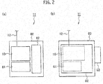
- the laser oscillator 11 includes, as illustrated in Figs. 2 (a) and 2(b) , a casing 60, a DDL module 10 accommodated in the casing 60 and connected to the transmission fiber 12, a power source unit 61 accommodated in the casing 60 and supplying power to the DDL module 10, a control module 62 accommodated in the casing 60 and controlling outputs of the DDL module 10 and others, and the like.
- a casing 60 a casing 60
- a DDL module 10 accommodated in the casing 60 and connected to the transmission fiber 12
- a power source unit 61 accommodated in the casing 60 and supplying power to the DDL module 10
- a control module 62 accommodated in the casing 60 and controlling outputs of the DDL module 10 and others, and the like.
- an air conditioning device 63 Arranged outside the casing 60 to adjust the temperature and humidity of the inside of the casing 60.
- the DDL module 10 overlaps and outputs a multiple-wavelength laser beam having multiple wavelengths ⁇ 1, ⁇ 2, ⁇ 3, ..., ⁇ n (hereinafter referred to as ⁇ i ⁇ ).
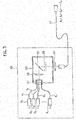
- the DDL module 10 includes a plurality of laser diodes (hereinafter referred to as "LDs") 3 1 , 3 2 , 3 3 , ..., 3n (n being an integer equal to or greater than 4), a spectral beam combining unit 50 connected through fibers 4 1 , 4 2 , 4 3 , ..., 4n to the LDs 3 1 , 3 2 , 3 3 , ..., 3n and carrying out spectral beam combining on the laser beams of multiple wavelengths ⁇ i ⁇ , and a condensing lens 54 that condenses a laser beam from the spectral beam combining unit 50 and makes the collected beam incident to the transmission fiber 12.
- LDs laser diodes
- Adoptable as the plurality of LDs 3 1 , 3 2 , 3 3 , ..., 3n are various kinds of semiconductor lasers. Combinations of kind and number for the plurality of LDs 3 are not particularly limited and are properly selected according to a sheet metal processing purpose.
- the wavelengths ⁇ 1, ⁇ 2, ⁇ 3, ..., ⁇ n of the plurality of LDs 3 are selectable from the ranges of, for example, smaller than 1000 nm, 800 nm to 990 nm, and 910 nm to 950 nm.
- the laser beams of multiple wavelengths ⁇ i ⁇ are managed and controlled block by block based on, for example, wavelength bands. Outputs of the laser beams are variably and individually adjusted depending on the wavelength bands thereof. Outputs of all wavelength bands are adjustable in such a way as to maintain a constant absorptance.
- a cutting process is achieved by simultaneously driving the plurality of LDs and by jetting a proper assist gas such as an oxygen or nitrogen gas to the vicinities of focusing positions.
- a proper assist gas such as an oxygen or nitrogen gas
- the laser beams with different wavelengths from the plurality of LDs cooperate with one another and with the assist gas such as an oxygen gas to melt the workpiece at high speed. Meltage is blown by the assist gas and the workpiece is speedily cut.
- the spectral beam combining unit 50 includes a fixing unit 51 that binds and fixes emitting ends of the fibers 4 1 , 4 2 , 4 3 , ..., 4 n to form a fiber array 4, a collimator lens 52 that makes the laser beams from the fibers 4 1 , 4 2 , 4 3 , ..., 4n parallel to one another, a diffraction grating 53 that diffracts the laser beams of multiple wavelengths ⁇ i ⁇ to make optical axes thereof coincide with one another, and a partial reflection coupler 55 that constitutes a resonator together with a reflection face arranged at rear ends of the plurality of LDs 3.
- the arranging position of the partial reflection coupler 55 illustrated in Fig. 3 is an example and is not particularly limited thereto.
- the wavelengths ⁇ i ⁇ of the laser beam When carrying out a cutting process or the like with such a DDL processing apparatus using the multiple-wavelength laser beam, the wavelengths ⁇ i ⁇ of the laser beam have their respective beam waists of, for example, about 100 micrometers to 400 micrometers. These plural diameters form multiple focal points.
- the beam waists are formed by optical elements including the condensing lens 18 having an incident diameter of about 2 mm to 20 mm and a focal length of 50 mm to 300 mm.
- Output of the laser oscillator 11 is variably controllable and adjustable wavelength by wavelength or wavelength band by wavelength band so that, at an incident angle of 0 to 40 degrees where an incident angle of 0 degrees is normal to a cut face of the workpiece W, an output from a wavelength band on a shorter wavelength side becomes higher than that from a wavelength band on a longer wavelength side.
- a cutting speed of the workpiece W is selectable in the range of, for example, 60 m/min to 250 m/min.
- deterioration (expiration of life) or failure of the plurality of LDs 3 or a misalignment of the optical elements in the spectral beam combining unit 50 may be a main cause of an output decrease of the multiple-wavelength laser beam.
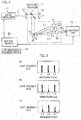
- the DDL processing apparatus further includes, as illustrated in Fig. 4 , a detecting mechanism 7 and a monitoring unit 73 connected to the detecting mechanism 7.
- the detecting mechanism 7 separates/samples part of the laser beam having the multiple wavelengths ⁇ 1, ⁇ 2, and ⁇ 3 and detects wavelength-by-wavelength light intensities of the sampled laser beam ( ⁇ 1, ⁇ 2, and ⁇ 3).
- the explanation here is made on the bases of the three wavelengths ⁇ 1, ⁇ 2, and ⁇ 3, the number of wavelengths is not limited to three.
- the detecting mechanism 7 is arranged between the collimator lens 15 and the condensing lens 18 and includes a splitting element 71 that separates the partial laser beam with wavelengths ⁇ 1, ⁇ 2, and ⁇ 3 passed through the collimator lens 15, a spectroscopic element 72 that disperses the separated laser beam according to the wavelengths ⁇ 1, ⁇ 2, and ⁇ 3, and detecting element groups 81, 82, and 83 that detect the dispersed laser beams of wavelengths ⁇ 1, ⁇ 2, and ⁇ 3, respectively. Transmission of the beams from the splitting element 71 to the detecting element groups 81, 82, and 83 is carried out through a space or fibers.
- Adoptable as the splitting element 71 is, for example, a beam splitter, a clad light stripper, or a like optical element.
- Adoptable as the spectroscopic element 72 is a diffraction grating, a prism, or a like optical element.
- the detecting element groups 81, 82, and 83 may be a single optical detector, a plurality of optical detectors, or a measuring device, capable of individually detecting, with a sufficient scope and resolution for carrying out an objective control operation, the dispersed beams within wavelength bands that respectively cover the wavelengths ⁇ 1, ⁇ 2, and ⁇ 3.
- a wavelength other than the wavelengths ⁇ 1, ⁇ 2, and ⁇ 3 may vary.
- detecting elements capable of measuring wavelengths other than the wavelengths ⁇ 1, ⁇ 2, and ⁇ 3 may be arranged in addition to the detecting element groups 81, 82, and 83.
- an optical spectrum analyzer or the like integrating and incorporating the spectroscopic element 72 and detecting element groups 81, 82, and 83 is employable.
- the monitoring unit 73 is a controller constituted with a central processing unit (CPU) or the like. According to detected results from the detecting element groups 81, 82, and 83, the monitoring unit 73 monitors output decreases of many laser beams. As illustrated in Fig. 5(a) , the monitoring unit 73 stores in advance in a memory or the like a normal-state intensity distribution (hereinafter referred to also as "wavelength profile") of the wavelengths ⁇ 1, ⁇ 2, and ⁇ 3. According to detected results from the detecting element groups 81, 82, and 83, the monitoring unit 73 evaluates a wavelength profile such as one illustrated in Fig. 5(b) . In Fig.
- an intensity of the wavelength ⁇ 2 is lower than that in the normal state. This is assumed to be caused by deterioration or failure of an LD corresponding to the wavelength ⁇ 2, or a misalignment of the LD corresponding to the wavelength ⁇ 2.
- the monitoring unit 73 compares the evaluated wavelength profile with the normal-state wavelength profile, and according to a change from the normal-state light intensities of the wavelengths ⁇ 1, ⁇ 2, and ⁇ 3, makes a determination on an output decrease.
- the evaluated wavelength profile illustrated in Fig. 5(b) shows that an intensity of at least one wavelength, i.e., the intensity of the wavelength ⁇ 2 has changed to the outside of a predetermined normal-state range. More precisely, it has decreased by a predetermined threshold or greater. In this case, the monitoring unit 73 determines that an output decrease has occurred.
- the monitoring unit 73 identifies as an abnormal LD the LD corresponding to the wavelength ⁇ 2.
- the predetermined threshold is set within an allowable range based on the normal-state wavelength profile and is stored in advance in a memory or the like of the monitoring unit 73.
- the monitoring unit 73 sends an alarm and information identifying the abnormal LD to the control module 62.
- the control module 62 is able to entirely stop the apparatus or display the identifying information of the abnormal LD on a display unit.
- the control module 62 may, according to the identifying information of the abnormal LD from the monitoring unit 73, stop the output of the abnormal LD and increase outputs of other normal LDs to compensate for the output of the abnormal LD. This results in bringing the sum of outputs of the wavelengths of the evaluated wavelength profile close to or equal to the sum of outputs of the wavelengths of the normal-state wavelength profile, thereby continuing the operation of the apparatus.
- the monitoring unit 73 generates, as illustrated in Fig. 5(c) , a wavelength profile involving intensity decreases in the wavelengths ⁇ 1 and ⁇ 3. This is assumed to be caused by a misalignment of the wavelength combining unit. If the intensities of the wavelengths ⁇ 1 and ⁇ 3 change/decrease by the predetermined threshold in the evaluated wavelength profile, the monitoring unit 73 determines that an output decrease has occurred and identifies LDs corresponding to the wavelengths ⁇ 1 and ⁇ 3 as abnormal LDs.
- the monitoring unit 73 determines the occurrence of an output decrease. In this case, the monitoring unit 73 sends an alarm and a comparison result of the wavelength profiles to the control module 62, so that the control module 62 may entirely stop the apparatus or display the comparison result of the wavelength profiles on the display unit.
- the control module 62 is also connected to a plurality of life measuring elements as a life measuring element group 74.
- the life measuring element group 74 is constituted with, for example, a plurality of PIN photodiodes or the like.
- the elements contained in the life measuring element group 74 are arranged in the vicinities of the LDs 31, 32, 33, ..., 3n illustrated in Fig. 3 .
- the life measuring element group 74 receives laser beams outputted from the LDs 31, 32, 33, ..., 3n, detects light intensities of the laser beams, and measures life (deterioration) or failure of the LDs 31, 32, 33, ..., 3n.
- the control module 62 stops output of an LD that has expired, deteriorated, or failed and increases outputs of other normal LDs to compensate for the output of the abnormal LD.
- the control module 62 may, according to the detected result from the life measuring element group 74, increase a control current value for the deteriorated LD close to a rated output.
- the control module 62 may identify/presume a cause of the output decrease of the multiple-wavelength laser beam. More precisely, if the LD specified by the abnormal LD identifying information from the monitoring unit 73 indicates no light intensity decrease, i.e. not detected as failed or deteriorated, according to the detected result from the life measuring element group 74, the control module 62 determines that the cause of the output decrease of the multiple-wavelength laser beam is not failure or deterioration of LDs but is a misalignment in the multiple-wavelength laser beam. This function may be provided for the monitoring unit 73 instead of the control module 62.
- the cause of an output decrease in the multiple-wavelength laser beam can be discriminated between failure or deterioration of LDs and a misalignment in the multiple-wavelength laser beam. If it is determined that the cause is a misalignment in the spectral beam combining unit 50, it is possible to avoid taking a countermeasure that is taken when LDs fail or deteriorate, i.e., a current increasing feedback to obtain a rated output. This prevents a fiber loss or fiber burning. Clarifying the cause of an output decrease results in taking a proper countermeasure.
- a beam parameter product deteriorates. Even if the output decrease is too small to raise a problem for the case employing a laser beam of a single wavelength, the BPP deterioration due to the output decrease may cause processing defects for the case employing a multiple-wavelength laser beam.
- the cause of the output decrease is a misalignment in the spectral beam combining unit 50, the laser beam made incidence to the transmission fiber 12 produces extreme heat to easily burn the fiber.
- identifying the cause of an output decrease as a misalignment in the spectral beam combining unit 50 enables the apparatus to be stopped at once even if the output decrease is too small to take a countermeasure that must be taken if LDs fail or deteriorate, thereby preventing the burning of the transmission fiber 12.
- control module 62 is able to determine (presume) that, according to only a monitored result from the monitoring unit 73, the cause of an output decrease is a misalignment in the spectral beam combining unit 50. More precisely, if the intensities of the wavelengths ⁇ 1 and ⁇ 3 drastically decrease as illustrated in Fig. 5(c) compared to the normal-state wavelength profile, or if the intensity of a wavelength band that is not oscillated and not expected to change changes, a determination (presumption) will be made that the cause is not the deterioration or failure of LDs but a misalignment in the spectral beam combining unit 50.
- step S1 the detecting mechanism 7 samples part of the multiple-wavelength laser beam emitted from the transmission fiber 12 and detects wavelength-by-wavelength light intensities of the sampled laser beam.
- step S2 the monitoring unit 73 generates, on the basis of the detected result from the detecting mechanism 7, a wavelength profile.
- the wavelength profile generated by the monitoring unit 73 is compared with the normal-state wavelength profile read out of the memory. If a change in the generated wavelength profile compared to the normal-state profile is equal to or greater than the predetermined threshold, it is determined that there is an abnormal LD and step S4 is carried out.
- step S4 the monitoring unit 73 provides the control module 62 with an alarm and information identifying the abnormal LD.
- the control module 62 receives the alarm and stops the apparatus.
- the embodiment of the present invention samples part of the multiple-wavelength laser beam, detects wavelength-by-wavelength light intensities of the sampled laser beam, and according to a change in the wavelength-by-wavelength light intensities (a wavelength profile) of the multiple-wavelength laser beam, monitors an output decrease in the multiple-wavelength laser beam.
- the embodiment controls the plurality of laser diodes. Namely, the embodiment properly monitors an output decrease and thereby prevents burning and processing defects caused by BPP increase.
- the detecting mechanism 7 is installed between the collimator lens 15 and the condensing lens 18, i.e. at the processing head, in the laser processing machine 13 and samples a laser beam emitted from the transmission fiber 12.
- This does not limit the present invention.
- it may be installed between the spectral beam combining unit 50 in the laser oscillator 11 illustrated in Fig. 3 and the transmission fiber 12.
- the detecting mechanism 7 detects a light intensity of an incident laser beam to be made incident to the transmission fiber 12.
- the detecting mechanism 7 may be installed at the location where the optical elements are present. The detecting mechanism 7 detects a light intensity of a laser beam emitted from the first fiber.
- Sheet metal processing to be carried out by the DDL processing apparatus according to the embodiment of the present invention includes not only cutting but also laser forming, annealing, abrading, and other kinds of sheet metal processing.
- the present invention thus provides the direct diode laser processing apparatus and output monitoring method, capable of properly monitoring an output decrease in a multiple-wavelength laser beam when using the multiple-wavelength laser beam for processing a workpiece.
Landscapes
- Physics & Mathematics (AREA)
- Optics & Photonics (AREA)
- Condensed Matter Physics & Semiconductors (AREA)
- General Physics & Mathematics (AREA)
- Electromagnetism (AREA)
- Engineering & Computer Science (AREA)
- Plasma & Fusion (AREA)
- Mechanical Engineering (AREA)
- Laser Beam Processing (AREA)
- Semiconductor Lasers (AREA)
Abstract
Description
- The present invention relates to a direct diode laser processing apparatus and an output monitoring method thereof.
- Known laser processing apparatuses for processing sheet metal employ, as a laser beam source, a carbon dioxide (CO2) gas laser oscillator, a YAG laser oscillator, or a fiber laser oscillator. The fiber laser oscillator is superior in beam quality to the YAG laser oscillator and has advantages of providing a very high oscillation efficiency and the like. Due to this, the fiber laser processing apparatus using the fiber laser oscillator is used in industrial fields, in particular, in sheet metal processing (cutting, welding, and the like).
- Developed in recent years is a direct diode laser (DDL) processing apparatus that uses, as a laser beam source, a direct diode laser oscillator. The DDL processing apparatus employs a plurality of laser diodes (LDs), superimposes laser beams into a multiple-wavelength laser beam, and transmits the laser beam through a transmission fiber to a processing head. The laser beam emitted from an end face of the transmission fiber is concentrated through and irradiated from collimating and condensing lenses onto a workpiece.
- As exemplified in Published
PCT International Application No. WO93/16512 - As exemplified in
Japanese Unexamined Patent Application Publication No. 2000-081370 - The Patent Literature 1, however, individually monitors output of a laser diode and is unable to monitor output of a multiple-wavelength laser beam used in the DDL processing apparatus. The Patent Literature 2 measures a change in wavelength according to a change in a light intensity ratio among polarized components. Output of the multiple-wavelength laser beam used in the DDL processing apparatus varies wavelength by wavelength, or wavelength band by wavelength band, and therefore, the technique of the Patent Literature 2 is inapplicable to the DDL processing apparatus.
- In consideration of the above-mentioned problems, the present invention provides a direct diode laser processing apparatus for processing a workpiece with a multiple-wavelength laser beam, capable of properly monitoring an output decrease in the multiple-wavelength laser beam. Also provided is an output monitoring method for the apparatus.
- According to an aspect of the present invention, the direct diode laser processing apparatus includes a laser oscillator that has a plurality of laser diodes to emit a multiple-wavelength laser beam, a transmission fiber that transmits the multiple-wavelength laser beam emitted from the laser oscillator, a laser processing machine that condenses the multiple-wavelength laser beam transmitted through the transmission fiber and processes a workpiece, a detecting mechanism that samples part of the multiple-wavelength laser beam and detects wavelength-by-wavelength light intensities of the sampled laser beam, a monitoring unit that monitors, according to a change in the wavelength-by-wavelength light intensities of the multiple-wavelength laser beam, an output decrease in the multiple-wavelength laser beam, and a control module that controls, according to a monitored result from the monitoring unit, outputs of the plurality of laser diodes. The output monitoring method is for the direct diode laser processing apparatus.
-
-
Figure 1 is a perspective view illustrating an example of a DDL processing apparatus according to an embodiment of the present invention. -
Figure 2(a) is a front view illustrating an example of a laser oscillator according to the embodiment of the present invention andFig. 2(b) is a side view illustrating the example of the laser oscillator according to the embodiment of the present invention. -
Figure 3 is a schematic view illustrating an example of a DDL module according to the embodiment of the present invention. -
Figure 4 is a schematic view illustrating examples of a detecting mechanism, a monitoring unit, and the vicinities thereof according to the embodiment of the present invention. -
Figure 5 (a) is a graph illustrating an example of a wavelength profile in a normal state,Fig. 5(b) is a graph illustrating an example of a generated wavelength profile, andFig. 5(c) is a graph illustrating another example of a generated wavelength profile. -
Figure 6 is a flowchart explaining an example of an output monitoring method for the DDL processing apparatus according to the embodiment of the present invention. - With reference to the drawings, an embodiment of the present invention will be explained. In the following description of the drawings, the same or like parts are represented with the same or like reference marks.
- With reference to
Fig. 1 , a general configuration of a direct diode laser (hereinafter referred to as "DDL") processing apparatus according to the embodiment of the present invention will be explained. The DDL processing apparatus according to the embodiment of the present invention includes, as illustrated inFig. 1 , alaser oscillator 11 that emits a multiple-wavelength laser beam LB, a transmission fiber (process fiber) 12 that transmits the laser beam LB emitted from thelaser oscillator 11, and alaser processing machine 13 that condenses the laser beam LB transmitted through thetransmission fiber 12 into one having a high-energy concentration and emits the same toward a workpiece (work) W. - The
laser processing machine 13 includes acollimator unit 14 that converts, through acollimator lens 15, the laser beam LB emitted from thetransmission fiber 12 into a substantial parallel beam, abend mirror 16 that reflects the laser beam LB converted into the substantial parallel beam in a downward Z-axis direction orthogonal to X- and Y-axis directions, and aprocessing head 17 that condenses, through acondensing lens 18, the laser beam LB reflected by thebend mirror 16. Employable as thecollimator lens 15 and condensinglens 18 are standard lenses such as fused silica plano-convex lenses. - Although not illustrated in
Fig. 1 , thecollimator unit 14 incorporates a lens driving unit that drives thecollimator lens 15 in a direction (X-axis direction) parallel to an optical axis. To control the lens driving unit, the DDL processing apparatus further includes a control unit. - The
laser processing machine 13 also includes a processing table 21 on which the workpiece W is placed, aportal X-axis carriage 22 that moves in the X-axis direction on the processing table 21, and a Y-axis carriage 23 that moves on theX-axis carriage 22 in the Y-axis direction orthogonal to the X-axis direction. Thecollimator lens 15 in thecollimator unit 14, thebend mirror 16, and thecondensing lens 18 in theprocessing head 17 are preliminarily adjusted to the optical axis, are fixed to the Y-axis carriage 23, and are moved together with the Y-axis carriage 23 in the Y-axis direction. It is possible to arrange a Z-axis carriage movable in an up-down direction with respect to the Y-axis carriage 23 and set the condensinglens 18 on the Z-axis carriage. - The DDL processing apparatus according to the embodiment irradiates the workpiece W with the laser beam LB that has been condensed through the condensing
lens 18 to have a smallest condensed diameter, i.e. minimum condensed diameter. While coaxially jetting an assist gas to remove meltage, the DDL processing apparatus moves theX-axis carriage 22 and Y-axis carriage 23. With this, the DDL processing apparatus cuts and processes the workpiece W. The workpiece W may be made from various materials such as stainless steel, mild steel, and aluminum. The thickness of the workpiece W may be, for example, about 0.1 mm to 100 mm. According to the embodiment, the thickness of the workpiece W is preferably 15 mm or greater. It may be 2 mm or greater, or may be 30 mm. It is preferable that the thickness is 100 mm or thinner. - With reference to
Figs. 2 and3 , thelaser oscillator 11 will be explained. Thelaser oscillator 11 includes, as illustrated inFigs. 2 (a) and 2(b) , acasing 60, aDDL module 10 accommodated in thecasing 60 and connected to thetransmission fiber 12, apower source unit 61 accommodated in thecasing 60 and supplying power to theDDL module 10, acontrol module 62 accommodated in thecasing 60 and controlling outputs of theDDL module 10 and others, and the like. Arranged outside thecasing 60 is anair conditioning device 63 to adjust the temperature and humidity of the inside of thecasing 60. - The
DDL module 10, as illustrated inFig. 3 , overlaps and outputs a multiple-wavelength laser beam having multiple wavelengths λ1, λ2, λ3, ..., λn (hereinafter referred to as {λi}). TheDDL module 10 includes a plurality of laser diodes (hereinafter referred to as "LDs") 31, 32, 33, ..., 3n (n being an integer equal to or greater than 4), a spectralbeam combining unit 50 connected throughfibers condensing lens 54 that condenses a laser beam from the spectralbeam combining unit 50 and makes the collected beam incident to thetransmission fiber 12. - Adoptable as the plurality of LDs 31, 32, 33, ..., 3n (hereinafter referred to as the plurality of LDs 3) are various kinds of semiconductor lasers. Combinations of kind and number for the plurality of LDs 3 are not particularly limited and are properly selected according to a sheet metal processing purpose. The wavelengths λ1, λ2, λ3, ..., λn of the plurality of LDs 3 are selectable from the ranges of, for example, smaller than 1000 nm, 800 nm to 990 nm, and 910 nm to 950 nm.
- The laser beams of multiple wavelengths {λi} are managed and controlled block by block based on, for example, wavelength bands. Outputs of the laser beams are variably and individually adjusted depending on the wavelength bands thereof. Outputs of all wavelength bands are adjustable in such a way as to maintain a constant absorptance.
- A cutting process is achieved by simultaneously driving the plurality of LDs and by jetting a proper assist gas such as an oxygen or nitrogen gas to the vicinities of focusing positions. With this, the laser beams with different wavelengths from the plurality of LDs cooperate with one another and with the assist gas such as an oxygen gas to melt the workpiece at high speed. Meltage is blown by the assist gas and the workpiece is speedily cut.
- The spectral
beam combining unit 50 includes afixing unit 51 that binds and fixes emitting ends of thefibers fiber array 4, acollimator lens 52 that makes the laser beams from thefibers partial reflection coupler 55 that constitutes a resonator together with a reflection face arranged at rear ends of the plurality of LDs 3. The arranging position of thepartial reflection coupler 55 illustrated inFig. 3 is an example and is not particularly limited thereto. - When carrying out a cutting process or the like with such a DDL processing apparatus using the multiple-wavelength laser beam, the wavelengths {λi} of the laser beam have their respective beam waists of, for example, about 100 micrometers to 400 micrometers. These plural diameters form multiple focal points. The beam waists are formed by optical elements including the condensing
lens 18 having an incident diameter of about 2 mm to 20 mm and a focal length of 50 mm to 300 mm. Output of thelaser oscillator 11 is variably controllable and adjustable wavelength by wavelength or wavelength band by wavelength band so that, at an incident angle of 0 to 40 degrees where an incident angle of 0 degrees is normal to a cut face of the workpiece W, an output from a wavelength band on a shorter wavelength side becomes higher than that from a wavelength band on a longer wavelength side. A cutting speed of the workpiece W is selectable in the range of, for example, 60 m/min to 250 m/min. - In the DDL processing apparatus, deterioration (expiration of life) or failure of the plurality of LDs 3 or a misalignment of the optical elements in the spectral
beam combining unit 50 may be a main cause of an output decrease of the multiple-wavelength laser beam. - To monitor output of the multiple-wavelength laser beam, the DDL processing apparatus according to the embodiment further includes, as illustrated in
Fig. 4 , a detectingmechanism 7 and amonitoring unit 73 connected to the detectingmechanism 7. The detectingmechanism 7 separates/samples part of the laser beam having the multiple wavelengths λ1, λ2, and λ3 and detects wavelength-by-wavelength light intensities of the sampled laser beam (λ1, λ2, and λ3). Although the explanation here is made on the bases of the three wavelengths λ1, λ2, and λ3, the number of wavelengths is not limited to three. - The detecting
mechanism 7 is arranged between thecollimator lens 15 and the condensinglens 18 and includes a splittingelement 71 that separates the partial laser beam with wavelengths λ1, λ2, and λ3 passed through thecollimator lens 15, aspectroscopic element 72 that disperses the separated laser beam according to the wavelengths λ1, λ2, and λ3, and detectingelement groups element 71 to the detectingelement groups - Adoptable as the splitting
element 71 is, for example, a beam splitter, a clad light stripper, or a like optical element. Adoptable as thespectroscopic element 72 is a diffraction grating, a prism, or a like optical element. The detectingelement groups beam combining unit 50 involves a misalignment, a wavelength other than the wavelengths λ1, λ2, and λ3 may vary. To deal with this, detecting elements capable of measuring wavelengths other than the wavelengths λ1, λ2, and λ3 may be arranged in addition to the detectingelement groups spectroscopic element 72 and detectingelement groups spectroscopic element 72 and detectingelement groups - The
monitoring unit 73 is a controller constituted with a central processing unit (CPU) or the like. According to detected results from the detectingelement groups monitoring unit 73 monitors output decreases of many laser beams. As illustrated inFig. 5(a) , themonitoring unit 73 stores in advance in a memory or the like a normal-state intensity distribution (hereinafter referred to also as "wavelength profile") of the wavelengths λ1, λ2, and λ3. According to detected results from the detectingelement groups monitoring unit 73 evaluates a wavelength profile such as one illustrated inFig. 5(b) . InFig. 5(b) , an intensity of the wavelength λ2 is lower than that in the normal state. This is assumed to be caused by deterioration or failure of an LD corresponding to the wavelength λ2, or a misalignment of the LD corresponding to the wavelength λ2. - The
monitoring unit 73 compares the evaluated wavelength profile with the normal-state wavelength profile, and according to a change from the normal-state light intensities of the wavelengths λ1, λ2, and λ3, makes a determination on an output decrease. For example, the evaluated wavelength profile illustrated inFig. 5(b) shows that an intensity of at least one wavelength, i.e., the intensity of the wavelength λ2 has changed to the outside of a predetermined normal-state range. More precisely, it has decreased by a predetermined threshold or greater. In this case, themonitoring unit 73 determines that an output decrease has occurred. At the same time, themonitoring unit 73 identifies as an abnormal LD the LD corresponding to the wavelength λ2. The predetermined threshold is set within an allowable range based on the normal-state wavelength profile and is stored in advance in a memory or the like of themonitoring unit 73. Themonitoring unit 73 sends an alarm and information identifying the abnormal LD to thecontrol module 62. - Receiving the alarm from the
monitoring unit 73, thecontrol module 62 is able to entirely stop the apparatus or display the identifying information of the abnormal LD on a display unit. Thecontrol module 62 may, according to the identifying information of the abnormal LD from themonitoring unit 73, stop the output of the abnormal LD and increase outputs of other normal LDs to compensate for the output of the abnormal LD. This results in bringing the sum of outputs of the wavelengths of the evaluated wavelength profile close to or equal to the sum of outputs of the wavelengths of the normal-state wavelength profile, thereby continuing the operation of the apparatus. - There will be a case that the
monitoring unit 73 generates, as illustrated inFig. 5(c) , a wavelength profile involving intensity decreases in the wavelengths λ1 and λ3. This is assumed to be caused by a misalignment of the wavelength combining unit. If the intensities of the wavelengths λ1 and λ3 change/decrease by the predetermined threshold in the evaluated wavelength profile, themonitoring unit 73 determines that an output decrease has occurred and identifies LDs corresponding to the wavelengths λ1 and λ3 as abnormal LDs. - It is possible that, if the sum of outputs of the wavelengths λ1, λ2, and λ3 in the evaluated wavelength profile decreases below the sum of outputs of the wavelengths λ1, λ2, and λ3 in the normal-state wavelength profile by a predetermined threshold or greater, the
monitoring unit 73 determines the occurrence of an output decrease. In this case, themonitoring unit 73 sends an alarm and a comparison result of the wavelength profiles to thecontrol module 62, so that thecontrol module 62 may entirely stop the apparatus or display the comparison result of the wavelength profiles on the display unit. - The
control module 62 is also connected to a plurality of life measuring elements as a life measuring element group 74. The life measuring element group 74 is constituted with, for example, a plurality of PIN photodiodes or the like. The elements contained in the life measuring element group 74 are arranged in the vicinities of theLDs Fig. 3 . The life measuring element group 74 receives laser beams outputted from theLDs LDs - According to a detected result from the life measuring element group 74, the
control module 62 stops output of an LD that has expired, deteriorated, or failed and increases outputs of other normal LDs to compensate for the output of the abnormal LD. Alternatively, thecontrol module 62 may, according to the detected result from the life measuring element group 74, increase a control current value for the deteriorated LD close to a rated output. - Also, according to the monitored result from the
monitoring unit 73 and the detected result from the life measuring element group 74, thecontrol module 62 may identify/presume a cause of the output decrease of the multiple-wavelength laser beam. More precisely, if the LD specified by the abnormal LD identifying information from themonitoring unit 73 indicates no light intensity decrease, i.e. not detected as failed or deteriorated, according to the detected result from the life measuring element group 74, thecontrol module 62 determines that the cause of the output decrease of the multiple-wavelength laser beam is not failure or deterioration of LDs but is a misalignment in the multiple-wavelength laser beam. This function may be provided for themonitoring unit 73 instead of thecontrol module 62. - With this, the cause of an output decrease in the multiple-wavelength laser beam can be discriminated between failure or deterioration of LDs and a misalignment in the multiple-wavelength laser beam. If it is determined that the cause is a misalignment in the spectral
beam combining unit 50, it is possible to avoid taking a countermeasure that is taken when LDs fail or deteriorate, i.e., a current increasing feedback to obtain a rated output. This prevents a fiber loss or fiber burning. Clarifying the cause of an output decrease results in taking a proper countermeasure. - If the cause of an output decrease is a misalignment in the spectral
beam combining unit 50, a beam parameter product (BPP) deteriorates. Even if the output decrease is too small to raise a problem for the case employing a laser beam of a single wavelength, the BPP deterioration due to the output decrease may cause processing defects for the case employing a multiple-wavelength laser beam. In addition, if the cause of the output decrease is a misalignment in the spectralbeam combining unit 50, the laser beam made incidence to thetransmission fiber 12 produces extreme heat to easily burn the fiber. Accordingly, identifying the cause of an output decrease as a misalignment in the spectralbeam combining unit 50 enables the apparatus to be stopped at once even if the output decrease is too small to take a countermeasure that must be taken if LDs fail or deteriorate, thereby preventing the burning of thetransmission fiber 12. - In some cases, the
control module 62 is able to determine (presume) that, according to only a monitored result from themonitoring unit 73, the cause of an output decrease is a misalignment in the spectralbeam combining unit 50. More precisely, if the intensities of the wavelengths λ1 and λ3 drastically decrease as illustrated inFig. 5(c) compared to the normal-state wavelength profile, or if the intensity of a wavelength band that is not oscillated and not expected to change changes, a determination (presumption) will be made that the cause is not the deterioration or failure of LDs but a misalignment in the spectralbeam combining unit 50. - With reference to a flowchart of
Fig. 6 , an example of an output monitoring method for the DDL processing apparatus according to the embodiment of the present invention will be explained. - In step S1, the detecting
mechanism 7 samples part of the multiple-wavelength laser beam emitted from thetransmission fiber 12 and detects wavelength-by-wavelength light intensities of the sampled laser beam. - In step S2, the
monitoring unit 73 generates, on the basis of the detected result from the detectingmechanism 7, a wavelength profile. In step S3, the wavelength profile generated by themonitoring unit 73 is compared with the normal-state wavelength profile read out of the memory. If a change in the generated wavelength profile compared to the normal-state profile is equal to or greater than the predetermined threshold, it is determined that there is an abnormal LD and step S4 is carried out. - In step S4, the
monitoring unit 73 provides thecontrol module 62 with an alarm and information identifying the abnormal LD. Thecontrol module 62 receives the alarm and stops the apparatus. - As explained above, the embodiment of the present invention samples part of the multiple-wavelength laser beam, detects wavelength-by-wavelength light intensities of the sampled laser beam, and according to a change in the wavelength-by-wavelength light intensities (a wavelength profile) of the multiple-wavelength laser beam, monitors an output decrease in the multiple-wavelength laser beam. According to the monitored result, the embodiment controls the plurality of laser diodes. Namely, the embodiment properly monitors an output decrease and thereby prevents burning and processing defects caused by BPP increase.
- Although the present invention has been explained on the basis of embodiment, it should not be understood that the explanation and drawings that form part of the disclosure limit the present invention. The disclosure may clarify, for persons skilled in the art, various substitutes, alternatives, and applications for the present invention.
- According to the embodiment of the present invention, the detecting
mechanism 7 is installed between thecollimator lens 15 and the condensinglens 18, i.e. at the processing head, in thelaser processing machine 13 and samples a laser beam emitted from thetransmission fiber 12. This does not limit the present invention. For example, it may be installed between the spectralbeam combining unit 50 in thelaser oscillator 11 illustrated inFig. 3 and thetransmission fiber 12. The detectingmechanism 7 detects a light intensity of an incident laser beam to be made incident to thetransmission fiber 12. - In a case where the
transmission fiber 12 illustrated inFig. 1 consists of two segments, i.e., a first transmission fiber connected to thelaser oscillator 11 and a second transmission fiber connected between the first transmission fiber and thelaser processing machine 13 and where the first and second transmission fibers are connected through optical elements such as beam couplers, the detectingmechanism 7 may be installed at the location where the optical elements are present. The detectingmechanism 7 detects a light intensity of a laser beam emitted from the first fiber. - Sheet metal processing to be carried out by the DDL processing apparatus according to the embodiment of the present invention includes not only cutting but also laser forming, annealing, abrading, and other kinds of sheet metal processing.
- In this way, the present invention naturally covers various embodiments and the like that are not explained herein. Accordingly, technical scopes of the present invention are determined only by invention specific matters that are pertinent to the above-mentioned explanation and the claims.
- The present invention thus provides the direct diode laser processing apparatus and output monitoring method, capable of properly monitoring an output decrease in a multiple-wavelength laser beam when using the multiple-wavelength laser beam for processing a workpiece.
- In connection with United States designation, this international patent application claims the benefit of priority under 35 U.S.C. 119(a) to
Japanese Patent Application No. 2014-209913 filed on October 14, 2014
Claims (9)
- A direct diode laser processing apparatus comprising:a laser oscillator including a plurality of laser diodes and emitting a multiple-wavelength laser beam;a transmission fiber transmitting the multiple-wavelength laser beam emitted from the laser oscillator;a laser processing machine collecting the multiple-wavelength laser beam transmitted through the transmission fiber and processing a workpiece;a detecting mechanism sampling part of the multiple-wavelength laser beam and detecting wavelength-by-wavelength light intensities of the sampled laser beam;a monitoring unit monitoring an output decrease in the multiple-wavelength laser beam according to a change in the wavelength-by-wavelength light intensities of the multiple-wavelength laser beam; anda control module controlling outputs of the plurality of laser diodes according to a monitored result from the monitoring unit,.
- The direct diode laser processing apparatus according to claim 1, wherein:the monitoring unit determines that there is an output decrease in the multiple-wavelength laser beam if any one of the wavelength-by-wavelength light intensities of the multiple-wavelength laser beam changes from a normal state by a predetermined threshold or greater and identifies a laser diode corresponding to the wavelength whose light intensity has decreased by the predetermined threshold or greater; andthe control module stops the output of the laser diode identified by the monitoring unit and increases outputs of other normal laser diodes to compensate for the output of the stopped laser diode.
- The direct diode laser processing apparatus according to claim 1, wherein:the monitoring unit determines that, if the sum of the wavelength-by-wavelength light intensities of the multiple-wavelength laser beam changes from that of a normal state by a predetermined threshold, there is an output decrease in the multiple-wavelength laser beam; andthe control module stops the apparatus if the monitoring unit determines that there is an output decrease in the multiple-wavelength laser beam.
- The direct diode laser processing apparatus according to any one of claims 1 to 3, further comprisinga plurality of photodiodes that detect light intensities of laser beams outputted from the plurality of laser diodes, respectively, whereinthe control module identifies and determines a cause of the output decrease in the multiple-wavelength laser beam according to the monitored result from the monitoring unit and the detected results from the plurality of photodiodes.
- The direct diode laser processing apparatus according to any one of claims 1 to 4, wherein the detecting mechanism includes:a splitting element that splits part of the multiple-wavelength laser beam;a spectroscopic element that spectroscopically separates the split laser beam wavelength by wavelength; anda detecting element group that detects the spectroscopically separated laser beams wavelength by wavelength.
- The direct diode laser processing apparatus according to any one of claims 1 to 5, whereinthe detecting mechanism is arranged in the laser processing machine and detects light intensities of the multiple-wavelength laser beam emitted from the transmission fiber.
- The direct diode laser processing apparatus according to any one of claims 1 to 5 wherein:the transmission fiber includes a first transmission fiber connected to the laser oscillator and a second transmission fiber connected between the first transmission fiber and the laser processing machine; andthe detecting mechanism is arranged between the first and second transmission fibers and detects light intensities of the multiple-wavelength laser beam emitted from the first transmission fiber.
- The direct diode laser processing apparatus according to any one of claims 1 to 5, wherein
the detecting mechanism is arranged in the laser oscillator and detects light intensities of the multiple-wavelength laser beam to be made incident to the transmission fiber. - An output monitoring method for the direct diode processing apparatus according to any one of claims 1 to 8, wherein:a step of sampling part of the multiple-wavelength laser beam and detecting wavelength-by-wavelength light intensities of the sampled laser beam; anda step of monitoring, according to a change in the wavelength-by-wavelength light intensities of the multiple-wavelength laser beam, an output decrease in the multiple-wavelength laser beam.
Applications Claiming Priority (2)
| Application Number | Priority Date | Filing Date | Title |
|---|---|---|---|
| JP2014209913A JP6373714B2 (en) | 2014-10-14 | 2014-10-14 | Direct diode laser processing apparatus and output monitoring method thereof |
| PCT/JP2015/078861 WO2016060095A1 (en) | 2014-10-14 | 2015-10-13 | Direct diode laser processing device and output monitoring method for same |
Publications (2)
| Publication Number | Publication Date |
|---|---|
| EP3210712A1 true EP3210712A1 (en) | 2017-08-30 |
| EP3210712A4 EP3210712A4 (en) | 2018-08-22 |
Family
ID=55746641
Family Applications (1)
| Application Number | Title | Priority Date | Filing Date |
|---|---|---|---|
| EP15851494.3A Withdrawn EP3210712A4 (en) | 2014-10-14 | 2015-10-13 | Direct diode laser processing device and output monitoring method for same |
Country Status (5)
| Country | Link |
|---|---|
| US (1) | US20170304942A1 (en) |
| EP (1) | EP3210712A4 (en) |
| JP (1) | JP6373714B2 (en) |
| CN (1) | CN107073643B (en) |
| WO (1) | WO2016060095A1 (en) |
Families Citing this family (20)
| Publication number | Priority date | Publication date | Assignee | Title |
|---|---|---|---|---|
| JP2018031622A (en) * | 2016-08-23 | 2018-03-01 | 三菱電機株式会社 | Determination apparatus and determination method |
| CN109982808B (en) * | 2016-11-22 | 2021-04-13 | 松下知识产权经营株式会社 | Laser processing apparatus and laser processing method |
| US10864600B2 (en) * | 2017-03-21 | 2020-12-15 | Mitsubishi Electric Corporation | Laser machining device |
| JP6619410B2 (en) * | 2017-12-05 | 2019-12-11 | ファナック株式会社 | Laser processing equipment |
| WO2019163069A1 (en) | 2018-02-22 | 2019-08-29 | 三菱電機株式会社 | Laser oscillation device |
| DE112018007199T5 (en) | 2018-04-02 | 2020-12-03 | Mitsubishi Electric Corporation | LASER DEVICE |
| EP3796490A4 (en) | 2018-05-18 | 2021-06-30 | Panasonic Intellectual Property Management Co., Ltd. | LASER OSCILLATION DEVICE FOR DIRECT DIODE LASER PROCESS AND FAULT DIAGNOSIS METHOD FOR LASER OSCILLATION DEVICE |
| US10985534B2 (en) | 2018-05-22 | 2021-04-20 | Panasonic Intellectual Property Management Co., Ltd. | Power and spectral monitoring in wavelength beam combining laser systems |
| JP6967487B2 (en) * | 2018-05-24 | 2021-11-17 | 本田技研工業株式会社 | Laser processing machine |
| JP6640920B2 (en) | 2018-06-12 | 2020-02-05 | 株式会社フジクラ | Fiber laser system and control method thereof |
| US11294193B2 (en) * | 2018-12-11 | 2022-04-05 | Northrop Grumman Systems Corporation | Wavelength-controlled beam stabilizer for spectrally beam combined laser sources |
| WO2020183729A1 (en) | 2019-03-14 | 2020-09-17 | 三菱電機株式会社 | Laser device and laser machining apparatus |
| JP6824355B1 (en) * | 2019-09-25 | 2021-02-03 | 株式会社アマダウエルドテック | Laser machining monitoring method and laser machining monitoring device |
| JP7695886B2 (en) * | 2019-11-13 | 2025-06-19 | ヌヴォトンテクノロジージャパン株式会社 | Laser Processing Equipment |
| JP7086922B2 (en) * | 2019-12-26 | 2022-06-20 | 株式会社フジクラ | Fiber laser system and its control method |
| WO2021220763A1 (en) * | 2020-04-27 | 2021-11-04 | パナソニックIpマネジメント株式会社 | Laser processing head and laser processing device |
| DE112021001183T5 (en) * | 2020-04-27 | 2022-12-29 | Panasonic Intellectual Property Management Co., Ltd. | LASER PROCESSING HEAD AND LASER PROCESSING DEVICE |
| US11769984B2 (en) * | 2021-07-30 | 2023-09-26 | Panasonic Holdings Corporation | Laser module, laser oscillator and laser processing system |
| CN116871680B (en) * | 2023-08-18 | 2024-02-20 | 广东海洋大学 | A laser optical path system for welding dissimilar materials |
| CN117589312B (en) * | 2024-01-16 | 2024-06-04 | 中国工程物理研究院激光聚变研究中心 | Wavelength following characteristic measuring device and method for semiconductor laser pumping source |
Family Cites Families (12)
| Publication number | Priority date | Publication date | Assignee | Title |
|---|---|---|---|---|
| NO307357B1 (en) * | 1997-02-14 | 2000-03-20 | Optoplan As | Device for painting optical wavelengths |
| EP1436931B1 (en) * | 2001-10-09 | 2005-12-28 | Infinera Corporation | Digital optical network architecture |
| JP2004114090A (en) * | 2002-09-26 | 2004-04-15 | Mitsubishi Heavy Ind Ltd | Laser machining method, and laser machining device |
| JP4757557B2 (en) * | 2005-07-29 | 2011-08-24 | ミヤチテクノス株式会社 | Laser processing head |
| KR100797239B1 (en) * | 2005-12-23 | 2008-01-23 | 주식회사 포스코 | Online detection device and method for welded part of steel sheet |
| US8309883B2 (en) * | 2010-05-20 | 2012-11-13 | Ipg Photonics Corporation | Methods and systems for laser processing of materials |
| ITPV20110011A1 (en) * | 2011-05-25 | 2012-11-26 | Alessandro Mantovani | CUTTING AND ABLATION PROCESS FOR PRODUCTION OF LEAD GRIDS FOR ACCUMULATORS USING LASER BEAM |
| JP2013062484A (en) * | 2011-08-24 | 2013-04-04 | Gigaphoton Inc | Laser device |
| EP2722127B1 (en) * | 2011-10-20 | 2016-01-13 | Nippon Steel & Sumitomo Metal Corporation | Laser processing device and laser processing method |
| JP2013207276A (en) * | 2012-03-29 | 2013-10-07 | Mitsubishi Electric Corp | Laser module |
| FR2997238B1 (en) * | 2012-10-22 | 2017-11-17 | Commissariat Energie Atomique | OPTICAL FIBER LASER AND METHOD FOR MANUFACTURING OPTICAL FIBER LASER |
| JP5942828B2 (en) * | 2012-12-07 | 2016-06-29 | 株式会社デンソー | Manufacturing method of semiconductor device |
-
2014
- 2014-10-14 JP JP2014209913A patent/JP6373714B2/en not_active Expired - Fee Related
-
2015
- 2015-10-13 CN CN201580053248.7A patent/CN107073643B/en active Active
- 2015-10-13 WO PCT/JP2015/078861 patent/WO2016060095A1/en not_active Ceased
- 2015-10-13 US US15/516,951 patent/US20170304942A1/en not_active Abandoned
- 2015-10-13 EP EP15851494.3A patent/EP3210712A4/en not_active Withdrawn
Also Published As
| Publication number | Publication date |
|---|---|
| US20170304942A1 (en) | 2017-10-26 |
| EP3210712A4 (en) | 2018-08-22 |
| JP2016078050A (en) | 2016-05-16 |
| JP6373714B2 (en) | 2018-08-15 |
| CN107073643B (en) | 2019-03-19 |
| CN107073643A (en) | 2017-08-18 |
| WO2016060095A1 (en) | 2016-04-21 |
Similar Documents
| Publication | Publication Date | Title |
|---|---|---|
| US20170304942A1 (en) | Direct diode laser processing apparatus and output monitoring method therfof | |
| RU2607502C2 (en) | Method for controlling a laser cutting process and laser cutting system implementing the same | |
| US10283934B2 (en) | Semiconductor laser oscillator | |
| US20130068738A1 (en) | Laser cutting head and method for cutting a workpiece by means of a laser cutting head | |
| JP5919356B2 (en) | Sheet metal processing method using laser light and laser processing apparatus for executing the same | |
| US10471537B2 (en) | Direct diode laser processing apparatus and sheet metal processing method using the same | |
| JP6367194B2 (en) | Workpiece processing apparatus using laser beam | |
| JP2014149494A (en) | Method for manufacturing optical transmission module | |
| US20220331911A1 (en) | Method for comparing laser processing systems and method for monitoring a laser processing process and associated laser processing system | |
| JP5595568B1 (en) | Laser processing equipment | |
| JP2016081994A (en) | Direct diode laser oscillator | |
| EP1202102B1 (en) | Laser microscope | |
| US20230080667A1 (en) | Laser welding monitoring device and laser welding monitoring method | |
| JP2016078047A (en) | Direct diode laser processing device and processing method for metal plate using the same | |
| US20170304940A1 (en) | Direct diode laser oscillator, direct diode laser processing apparatus, and reflected light detecting method | |
| JP2016078051A (en) | Direct diode laser processing apparatus and sheet metal processing method using the same | |
| CN113543922B (en) | Laser processing device | |
| JP6043773B2 (en) | Sheet metal processing method using direct diode laser light and direct diode laser processing apparatus for executing the same | |
| JP2016221545A (en) | Laser processing device, and converging angle setting method for laser processing device | |
| WO2016059949A1 (en) | Direct diode laser processing device and sheet metal processing method using same | |
| JP6035303B2 (en) | Direct diode laser processing apparatus and metal plate processing method using the same | |
| JP7620794B2 (en) | Laser processing head and laser processing device | |
| JP2018190905A (en) | Laser equipment | |
| JP7620793B2 (en) | Laser processing head and laser processing device | |
| US20250012727A1 (en) | Optical axis adjustment method for laser module and optical axis adjustment jig |
Legal Events
| Date | Code | Title | Description |
|---|---|---|---|
| PUAI | Public reference made under article 153(3) epc to a published international application that has entered the european phase |
Free format text: ORIGINAL CODE: 0009012 |
|
| 17P | Request for examination filed |
Effective date: 20170512 |
|
| AK | Designated contracting states |
Kind code of ref document: A1 Designated state(s): AL AT BE BG CH CY CZ DE DK EE ES FI FR GB GR HR HU IE IS IT LI LT LU LV MC MK MT NL NO PL PT RO RS SE SI SK SM TR |
|
| AX | Request for extension of the european patent |
Extension state: BA ME |
|
| DAV | Request for validation of the european patent (deleted) | ||
| DAX | Request for extension of the european patent (deleted) | ||
| A4 | Supplementary search report drawn up and despatched |
Effective date: 20180724 |
|
| RIC1 | Information provided on ipc code assigned before grant |
Ipc: H01S 5/0683 20060101ALI20180718BHEP Ipc: B23K 26/00 20140101AFI20180718BHEP |
|
| GRAP | Despatch of communication of intention to grant a patent |
Free format text: ORIGINAL CODE: EPIDOSNIGR1 |
|
| INTG | Intention to grant announced |
Effective date: 20200128 |
|
| RAP1 | Party data changed (applicant data changed or rights of an application transferred) |
Owner name: AMADA HOLDINGS CO., LTD. Owner name: LUMENTUM OPERATIONS LLC |
|
| STAA | Information on the status of an ep patent application or granted ep patent |
Free format text: STATUS: THE APPLICATION IS DEEMED TO BE WITHDRAWN |
|
| 18D | Application deemed to be withdrawn |
Effective date: 20200609 |