EP3210507B1 - Air fryer - Google Patents
Air fryer Download PDFInfo
- Publication number
- EP3210507B1 EP3210507B1 EP16190724.1A EP16190724A EP3210507B1 EP 3210507 B1 EP3210507 B1 EP 3210507B1 EP 16190724 A EP16190724 A EP 16190724A EP 3210507 B1 EP3210507 B1 EP 3210507B1
- Authority
- EP
- European Patent Office
- Prior art keywords
- air
- pot
- handle
- cover
- blade
- Prior art date
- Legal status (The legal status is an assumption and is not a legal conclusion. Google has not performed a legal analysis and makes no representation as to the accuracy of the status listed.)
- Active
Links
- 238000010438 heat treatment Methods 0.000 claims description 29
- 238000005485 electric heating Methods 0.000 claims description 7
- 239000011229 interlayer Substances 0.000 claims description 7
- 239000002184 metal Substances 0.000 claims description 7
- 238000004080 punching Methods 0.000 claims description 3
- 235000013305 food Nutrition 0.000 description 7
- 230000000694 effects Effects 0.000 description 2
- 241000270295 Serpentes Species 0.000 description 1
- 238000004140 cleaning Methods 0.000 description 1
- 230000007812 deficiency Effects 0.000 description 1
- 230000003670 easy-to-clean Effects 0.000 description 1
- 230000017525 heat dissipation Effects 0.000 description 1
- 238000009434 installation Methods 0.000 description 1
- 235000013372 meat Nutrition 0.000 description 1
- 238000000034 method Methods 0.000 description 1
- 230000002093 peripheral effect Effects 0.000 description 1
- 238000003825 pressing Methods 0.000 description 1
- 235000011888 snacks Nutrition 0.000 description 1
- 238000003860 storage Methods 0.000 description 1
- 235000013311 vegetables Nutrition 0.000 description 1
Images


Classifications
-
- A—HUMAN NECESSITIES
- A47—FURNITURE; DOMESTIC ARTICLES OR APPLIANCES; COFFEE MILLS; SPICE MILLS; SUCTION CLEANERS IN GENERAL
- A47J—KITCHEN EQUIPMENT; COFFEE MILLS; SPICE MILLS; APPARATUS FOR MAKING BEVERAGES
- A47J37/00—Baking; Roasting; Grilling; Frying
- A47J37/06—Roasters; Grills; Sandwich grills
- A47J37/0623—Small-size cooking ovens, i.e. defining an at least partially closed cooking cavity
- A47J37/0629—Small-size cooking ovens, i.e. defining an at least partially closed cooking cavity with electric heating elements
- A47J37/0641—Small-size cooking ovens, i.e. defining an at least partially closed cooking cavity with electric heating elements with forced air circulation, e.g. air fryers
-
- A—HUMAN NECESSITIES
- A47—FURNITURE; DOMESTIC ARTICLES OR APPLIANCES; COFFEE MILLS; SPICE MILLS; SUCTION CLEANERS IN GENERAL
- A47J—KITCHEN EQUIPMENT; COFFEE MILLS; SPICE MILLS; APPARATUS FOR MAKING BEVERAGES
- A47J37/00—Baking; Roasting; Grilling; Frying
- A47J37/12—Deep fat fryers, e.g. for frying fish or chips
- A47J37/1204—Deep fat fryers, e.g. for frying fish or chips for domestic use
- A47J37/1209—Deep fat fryers, e.g. for frying fish or chips for domestic use electrically heated
-
- A—HUMAN NECESSITIES
- A47—FURNITURE; DOMESTIC ARTICLES OR APPLIANCES; COFFEE MILLS; SPICE MILLS; SUCTION CLEANERS IN GENERAL
- A47J—KITCHEN EQUIPMENT; COFFEE MILLS; SPICE MILLS; APPARATUS FOR MAKING BEVERAGES
- A47J37/00—Baking; Roasting; Grilling; Frying
- A47J37/12—Deep fat fryers, e.g. for frying fish or chips
- A47J37/1257—Deep fat fryers, e.g. for frying fish or chips electrically heated
- A47J37/1261—Details of the heating elements; Fixation of the heating elements to the frying vessel
-
- A—HUMAN NECESSITIES
- A47—FURNITURE; DOMESTIC ARTICLES OR APPLIANCES; COFFEE MILLS; SPICE MILLS; SUCTION CLEANERS IN GENERAL
- A47J—KITCHEN EQUIPMENT; COFFEE MILLS; SPICE MILLS; APPARATUS FOR MAKING BEVERAGES
- A47J37/00—Baking; Roasting; Grilling; Frying
- A47J37/12—Deep fat fryers, e.g. for frying fish or chips
- A47J37/1276—Constructional details
-
- A—HUMAN NECESSITIES
- A47—FURNITURE; DOMESTIC ARTICLES OR APPLIANCES; COFFEE MILLS; SPICE MILLS; SUCTION CLEANERS IN GENERAL
- A47J—KITCHEN EQUIPMENT; COFFEE MILLS; SPICE MILLS; APPARATUS FOR MAKING BEVERAGES
- A47J37/00—Baking; Roasting; Grilling; Frying
- A47J37/12—Deep fat fryers, e.g. for frying fish or chips
- A47J37/1295—Frying baskets or other food holders
Definitions
- the present invention related to an electric fryer, which is an air fryer.
- the electrical fryer is a household appliance for frying various foods, such as meat, vegetable, fried dough twist and snacks, etc. With advantages as easy operation, rapid heating rate, the fryer is special equipment for snake bar, and a necessary kitchenware for modern life. While air fryer is a new household appliance for frying foods with application of high-speed air cycle technique. The air fryer is able to reduce 80% of oil and fat than that of food produced by traditional electric fryers. It is easy to clean, and is safe and economical, thus is favored by people.
- Such air fryer combine rapid cycle hot air and oven part uniquely, as disclosed in Chinese Patent Document-Application Number: 201310101037.9 published under CN 103142151 A , Application Announcement Date: 2013.06.12, Invention Name "A Smoke-free Air Fryer", the air fryer comprises fixed part and mobile part.
- the said air fryer has a top-moving power switch that is equipped at one lower side of the boss (for installing timer) at the front fixed part.
- the mobile part of the air fryer and food storage containers are locked, one upper side of the handle matched for unlocking is equipped with top-moving boss, and the top-moving boss is matched with top-moving power switch at one lower side of the boss of the fixed part.
- Flat spiral type electric heating tube is below the hot-air fan in the fixed part, whose power connector is connected with inner wall of the fixed part through connecting pieces.
- the tube body of the flat spiral type electric heating tube is elastically connected with inner wall of the fixed part through spring.
- the bottom center of the drip pan of the mobile part of the said air fryer is arc-shaped raised, with peripheral pot walls and the pot bottom to be arc-shaped.
- safety and cold-hot wind circulation structure, etc of the said air fryer are still need to be further improved.
- the invention is aimed to provide an air fryer, and solve problems among existing similar products such as weak structure design, safety and oil filter structure, etc.
- the goal is achieved by following technical solutions.
- An air fryer comprising a lower casing, an upper casing, a blade motor, a temperature switch, a cold-air blade, a hot-air blade, a spiral electric heating tube, a handle, an inner pot, a base, an outer pot, and a pot housing; the said pot housing, inner pot, outer pot and handle are integrated into a pot body, while the upper casing, the lower casing and the base are integrated into an engine body.
- the base is equipped with a bottom cover.
- the side of the base symmetrical with the handle is equipped with a wiring sleeve, and the pot body is placed in the opening of one lower side of the engine body.
- the pot housing is arc-shaped; the pot housing and the engine body form a complete conical body which is small at the top and big at the bottom.
- the handle is protruding out of the engine body.
- the upper part of the engine body is equipped with a spiral electric heating pipe and a blade motor whose spindle is connected with a cold-air blade and a hot-air blade to blow hot air inside the engine body into the inner spot by rotating the cold-air blade and the hot-air blade, and then be discharged.
- the cold air goes into the engine body, one part of the cold air be discharged, and the rest be heated to hot air;
- the key structure design is that a skirt of the outer pot beside on both sides of the handle is equipped with flat key holes symmetrically, and flat key holes are corresponding to through holes inside the upper casing.
- the through holes are located between inner diameter of an interlayer cover and the external diameter of a heat shield cover.
- At two sides of upper casing above the through holes are symmetrical upper air-holes, and the base at two sides of wiring sleeves is equipped with lower air-holes.
- the gap between inner diameter of the heat shield cover and external diameter of a heating tube cover, and the heating tube is opposed to the pot mouth.
- the said gap between the heat shield cover and the heating tube cover is connected with external diameter of the engine body through an air outlet plate which is located at one side of the engine body symmetrical to the handle; the cold-air blade and hot-air blade inside the upper casing is separated by the heat shield cover, and the hot-air blade inside the upper casing is opposed to the air inlet hole of the heating tube cover.
- the air inlet hole of the heating tube cover is equipped with hot-air mesh, and a spiral heating tube is equipped inside the heating tube cover.
- the controller and blade motor are equipped inside the cavity between outer diameter of interlayer cover and inner diameter of the upper casing.
- the upper casing top and the upper cover are inclined to the handle.
- the upper cover at the top of upper casing is equipped with the temperature switch, which partly protrudes out of an arc-shaped groove at the top of upper casing.
- the upper casing at the handle side is equipped with a time switch that is located at the engine body above the handle.
- the spiral electrical heating tube, the temperature switch, the time switch and the blade motor are connected with controller through a line.
- the said structure has realized the hot-air and cold-air circulation with closing matching components, and is in accordant with requirements for heating and stability.
- the air fryer is easy to assemble, to produce and to clean, with good heating and heat dissipation effect, and beautiful appearance.
- the center of inner bottom of the said outer spot is raised, and the inner bottom of inner pot is equipped with oil-filter screen that is fixed by the clips inside the hole of inner pot.
- the hole of the inner pot is equipped with a small protruding edge whose diameter is smaller than the diameter of the oil filter screen.
- the said outer pot is connected with pot housing through a screw, and one side of the inner pot inside the outer pot is connected with the handle through connecting pieces.
- the handle and the pot housing are connected through a locking plate.
- the locking plate is L-shaped, with one end sticking into the pot housing and fitting with a metal sheet on the inner wall of the pot housing, and the other end against a locking sheet through a tilted cover.
- the locking sheet at the handle side is tilted.
- the shaft end of the tilted cover insert into the plate hole of the locking plate, and the pivot at the curved point of the locking plate is fixed in the handle.
- the locking plate When the locking sheet is pressed, the locking plate will be driven by the tilted cover to rotate, and the locking part of the locking plate will be separated from the metal sheet.
- the said structure is easy to dismount the inner pot and outer pot, and to achieve good safety.
- the bottom of the pot housing is equipped with a housing hook, and the base corresponding to the hook is equipped with a hook hole corresponding to the housing hook; when the pot body is placed into the engine body, the housing hook fits with the hook hole of the base.
- the said structure is able to prevent the pot body from being taken out arbitrarily and to improve the safety of the air fryer during the working.
- the handle at a projecting edge of the said housing is equipped with a raised limiting diagonal bar
- the upper casing corresponding to the limiting diagonal bar of the handle is equipped with a column plate
- a limiting column inside the upper casing is pushed out of column plate by a spring, and touches the beveled side of the limiting diagonal bar.
- the said cold-air blade and hot-air blade are plane blades with tilted back blades respectively.
- the back blade for cold-air blade is tilted upward; while back lade for hot-air blade is tilted downward. Meanwhile, the back blades are equipped with corresponding guiding punching grooves.
- the said structure has further improved the hot air and cold air circulation effect, and has reduced the space occupancy of blades.
- the said upper casing between the time switch and the handle is equipped with an indicator light, and the base at two sides of the handle is equipped with a corner groove respectively.
- the said structure is easy for indicating the working state of the air fryer, and for moving the air fryer.
- the invention has reasonable designed structure, and is easy to produce, operate and clean, with good stability, safety and beautiful appearance; mainly used as air fryer, and for structure improvement of similar products.
- the pot body of the air fryer is integrated by a pot housing 26, an outer pot 25, an inner pot 20 and a handle 19, specific as: the outer pot is connected with the pot housing through a screw, and one side of the inner pot inside the outer pot is connected with the handle through connecting pieces 15.
- the handle and the pot housing are connected through a locking plate 18.
- the locking plate is L-shaped, with one end sticking into the pot housing and fitting with a metal sheet on the inner wall of the pot housing, and the other end against a locking sheet 16 through a tilted cover 17. The locking sheet at the handle side is tilted.
- the shaft end of the tilted cover inserts into the plate hole of the locking plate, and the pivot at the curved point of the locking plate is fixed in the handle.
- the locking plate will be driven by the tilted cover to rotate, and the locking part of the locking plate will be separated from the metal sheet.
- the center of inner diameter bottom of the outer spot is raised, and the inner diameter bottom of inner pot is equipped with an oil-filter screen 21 that is fixed by clips inside the hole of inner pot.
- the hole of the inner pot is equipped with a small protruding edge whose diameter is smaller than the diameter of the oil filter screen.
- the bottom of the pot housing is equipped with a housing hook 2601, and the base 22 corresponding to the hook is equipped with a hook hole; when placing the pot body into the engine body, the housing hook will fit with the hook hole of the base.
- the handle at the protruding edge of the said housing is equipped with a raised limiting diagonal bar 1901, the upper casing 3 corresponding to the limiting diagonal bar of the handle is equipped with a column plate 28, and a limiting column 27 inside the upper casing is pushed out of the column plate through a spring, and touches the beveled side of the limiting diagonal bar.
- the upper casing 1, lower casing 3 and base 22 are integrated into the engine body.
- the base is equipped with a bottom cover 23.
- the side of the base symmetrical with the handle is equipped with a wiring sleeve 24, and the pot body is placed in the opening of one lower side of the engine body.
- the pot housing 26 is arc-shaped; the pot housing and the engine body form a complete conical body which is small at the top and big at the bottom.
- the handle protrudes out of the engine body.
- the upper part of the engine body is equipped with a spiral electric heating pipe 14 and a blade motor 5 whose spindle is connected with a cold-air blade 7 and a hot-air blade 10 to blow hot air inside the engine body into the inner spot by rotating the cold-air blade and the hot-air blade, and then be discharged.
- the cold air goes into the engine body, one part of the cold air is discharged, and the rest is heated to hot air.
- the specific structures are as follows:
- a skirt of the outer pot 25 at both sides of the handle 19 is equipped with flat key holes symmetrically, and flat key holes are corresponding to through holes inside the upper casing. The through holes are located between inner diameter of an interlayer cover 9 and the external diameter of a heat shield cover 11.
- the base 22 at two sides of wiring sleeves are equipped with lower air-holes.
- the gap between inner diameter of the heat shield cover and external diameter of the heating tube cover 12, and the heating tube is opposed to the pot mouth.
- the said gap between heat shield cover and heating tube cover is connected with external diameter of engine body through an air outlet plate 2 which is located at one side of the engine body symmetrical to the handle.
- the cold-air blade and hot-air blade inside the upper casing is separated by the heat shield cover.
- the said cold-air blade and hot-air blade are plane blades with tilted back blades respectively.
- the back blade for cold-air blade is tilted upward; while back blade for hot-air blade is tilted downward. Meanwhile, the back blades are equipped with corresponding guiding punching grooves.
- the hot-air blade inside the upper casing is opposed to the air inlet hole of the heating tube cover.
- the air inlet hole of the heating tube pipe is equipped with hot-air mesh 13
- the spiral heating tube is equipped inside the heating tube cover.
- the controller and blade motor are equipped inside the cavity between outer diameter of interlayer cover and inner diameter of upper casing.
- the upper casing top and the upper cover 4 are inclined to the handle.
- the upper cover at the top of upper casing is equipped with a temperature switch 6, which partly protrudes out of the arc-shaped groove at the top of upper casing.
- the upper casing at the handle side is equipped with a time switch 8 that is located at the engine body above the handle.
- the spiral electrical heating tube, the temperature switch, the time switch and the blade motor are connected with a controller through a line.
- the upper casing between the time switch and the handle is equipped with an indicator light, and the base at two sides of the handle is equipped with corner groove respectively.
- the limiting column is equipped inside the independent cavity of the upper engine body.
Description
- The present invention related to an electric fryer, which is an air fryer.
- The electrical fryer is a household appliance for frying various foods, such as meat, vegetable, fried dough twist and snacks, etc. With advantages as easy operation, rapid heating rate, the fryer is special equipment for snake bar, and a necessary kitchenware for modern life. While air fryer is a new household appliance for frying foods with application of high-speed air cycle technique. The air fryer is able to reduce 80% of oil and fat than that of food produced by traditional electric fryers. It is easy to clean, and is safe and economical, thus is favored by people. Such air fryer combine rapid cycle hot air and oven part uniquely, as disclosed in Chinese Patent Document-Application Number:
201310101037.9 CN 103142151 A , Application Announcement Date: 2013.06.12, Invention Name "A Smoke-free Air Fryer", the air fryer comprises fixed part and mobile part. The said air fryer has a top-moving power switch that is equipped at one lower side of the boss (for installing timer) at the front fixed part. The mobile part of the air fryer and food storage containers are locked, one upper side of the handle matched for unlocking is equipped with top-moving boss, and the top-moving boss is matched with top-moving power switch at one lower side of the boss of the fixed part. Flat spiral type electric heating tube is below the hot-air fan in the fixed part, whose power connector is connected with inner wall of the fixed part through connecting pieces. The tube body of the flat spiral type electric heating tube is elastically connected with inner wall of the fixed part through spring. The bottom center of the drip pan of the mobile part of the said air fryer is arc-shaped raised, with peripheral pot walls and the pot bottom to be arc-shaped. However, safety and cold-hot wind circulation structure, etc of the said air fryer are still need to be further improved. - To over the said deficiencies, the invention is aimed to provide an air fryer, and solve problems among existing similar products such as weak structure design, safety and oil filter structure, etc. The goal is achieved by following technical solutions.
- An air fryer, comprising a lower casing, an upper casing, a blade motor, a temperature switch, a cold-air blade, a hot-air blade, a spiral electric heating tube, a handle, an inner pot, a base, an outer pot, and a pot housing; the said pot housing, inner pot, outer pot and handle are integrated into a pot body, while the upper casing, the lower casing and the base are integrated into an engine body. The base is equipped with a bottom cover. The side of the base symmetrical with the handle is equipped with a wiring sleeve, and the pot body is placed in the opening of one lower side of the engine body. The pot housing is arc-shaped; the pot housing and the engine body form a complete conical body which is small at the top and big at the bottom. The handle is protruding out of the engine body. The upper part of the engine body is equipped with a spiral electric heating pipe and a blade motor whose spindle is connected with a cold-air blade and a hot-air blade to blow hot air inside the engine body into the inner spot by rotating the cold-air blade and the hot-air blade, and then be discharged. The cold air goes into the engine body, one part of the cold air be discharged, and the rest be heated to hot air; the key structure design is that a skirt of the outer pot beside on both sides of the handle is equipped with flat key holes symmetrically, and flat key holes are corresponding to through holes inside the upper casing. The through holes are located between inner diameter of an interlayer cover and the external diameter of a heat shield cover. At two sides of upper casing above the through holes are symmetrical upper air-holes, and the base at two sides of wiring sleeves is equipped with lower air-holes. The gap between inner diameter of the heat shield cover and external diameter of a heating tube cover, and the heating tube is opposed to the pot mouth. The said gap between the heat shield cover and the heating tube cover is connected with external diameter of the engine body through an air outlet plate which is located at one side of the engine body symmetrical to the handle; the cold-air blade and hot-air blade inside the upper casing is separated by the heat shield cover, and the hot-air blade inside the upper casing is opposed to the air inlet hole of the heating tube cover. The air inlet hole of the heating tube cover is equipped with hot-air mesh, and a spiral heating tube is equipped inside the heating tube cover. The controller and blade motor are equipped inside the cavity between outer diameter of interlayer cover and inner diameter of the upper casing. The upper casing top and the upper cover are inclined to the handle. The upper cover at the top of upper casing is equipped with the temperature switch, which partly protrudes out of an arc-shaped groove at the top of upper casing. The upper casing at the handle side is equipped with a time switch that is located at the engine body above the handle. The spiral electrical heating tube, the temperature switch, the time switch and the blade motor are connected with controller through a line. The said structure has realized the hot-air and cold-air circulation with closing matching components, and is in accordant with requirements for heating and stability. In the same time, the air fryer is easy to assemble, to produce and to clean, with good heating and heat dissipation effect, and beautiful appearance.
- The center of inner bottom of the said outer spot is raised, and the inner bottom of inner pot is equipped with oil-filter screen that is fixed by the clips inside the hole of inner pot. The hole of the inner pot is equipped with a small protruding edge whose diameter is smaller than the diameter of the oil filter screen. The said structure is easy for hot-air to enter into the inner pot after it entering into the outer pot and inner pot, and to have efficient and sufficient heating for foods on the oil filter screen; in the same time, the structure is easy for dismounting and cleaning the oil filter screen.
- The said outer pot is connected with pot housing through a screw, and one side of the inner pot inside the outer pot is connected with the handle through connecting pieces. The handle and the pot housing are connected through a locking plate. The locking plate is L-shaped, with one end sticking into the pot housing and fitting with a metal sheet on the inner wall of the pot housing, and the other end against a locking sheet through a tilted cover. The locking sheet at the handle side is tilted. The shaft end of the tilted cover insert into the plate hole of the locking plate, and the pivot at the curved point of the locking plate is fixed in the handle. When the locking sheet is pressed, the locking plate will be driven by the tilted cover to rotate, and the locking part of the locking plate will be separated from the metal sheet. The said structure is easy to dismount the inner pot and outer pot, and to achieve good safety.
- The bottom of the pot housing is equipped with a housing hook, and the base corresponding to the hook is equipped with a hook hole corresponding to the housing hook; when the pot body is placed into the engine body, the housing hook fits with the hook hole of the base. The said structure is able to prevent the pot body from being taken out arbitrarily and to improve the safety of the air fryer during the working.
- The handle at a projecting edge of the said housing is equipped with a raised limiting diagonal bar, the upper casing corresponding to the limiting diagonal bar of the handle is equipped with a column plate, and a limiting column inside the upper casing is pushed out of column plate by a spring, and touches the beveled side of the limiting diagonal bar. The said structure is able to prevent ensure that the pot body not be taken out arbitrarily, which has further improved the safety of the air fryer during the working. In the same time, with matched housing hook at the bottom, the pot body can only been taken out by drawing out after driving the pot body tilted downward and outward through the handle.
- The said cold-air blade and hot-air blade are plane blades with tilted back blades respectively. The back blade for cold-air blade is tilted upward; while back lade for hot-air blade is tilted downward. Meanwhile, the back blades are equipped with corresponding guiding punching grooves. The said structure has further improved the hot air and cold air circulation effect, and has reduced the space occupancy of blades.
- The said upper casing between the time switch and the handle is equipped with an indicator light, and the base at two sides of the handle is equipped with a corner groove respectively. The said structure is easy for indicating the working state of the air fryer, and for moving the air fryer.
- The invention has reasonable designed structure, and is easy to produce, operate and clean, with good stability, safety and beautiful appearance; mainly used as air fryer, and for structure improvement of similar products.
-
-
FIG. 1 is cross-sectional view I of the invention; wherein, A part is framed, and arrows indicate the direction of hot air. -
FIG. 2 is cross-sectional view II of the invention, wherein, arrows indicate the direction of cold air. -
FIG. 3 is enlarged view of A part ofFIG.1 . -
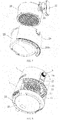
FIG. 4 is three-dimensional structure view of the invention. -
FIG. 5 is structural view of the invention when pot boy been taken out. -
FIG. 6 is structural view I of the invention when pots been separated -
FIG. 7 is structural view II of the invention when pots been separated -
FIG. 8 is inner structural view of engine part of the invention. - Turning to the drawings, and further description of structure and usage of the invention is provided. As shown in
FIG1-8 , the pot body of the air fryer is integrated by apot housing 26, anouter pot 25, aninner pot 20 and ahandle 19, specific as: the outer pot is connected with the pot housing through a screw, and one side of the inner pot inside the outer pot is connected with the handle through connectingpieces 15. The handle and the pot housing are connected through a lockingplate 18. The locking plate is L-shaped, with one end sticking into the pot housing and fitting with a metal sheet on the inner wall of the pot housing, and the other end against a lockingsheet 16 through a tiltedcover 17. The locking sheet at the handle side is tilted. The shaft end of the tilted cover inserts into the plate hole of the locking plate, and the pivot at the curved point of the locking plate is fixed in the handle. When pressing the locking sheet, the locking plate will be driven by the tilted cover to rotate, and the locking part of the locking plate will be separated from the metal sheet. In the same time, the center of inner diameter bottom of the outer spot is raised, and the inner diameter bottom of inner pot is equipped with an oil-filter screen 21 that is fixed by clips inside the hole of inner pot. The hole of the inner pot is equipped with a small protruding edge whose diameter is smaller than the diameter of the oil filter screen. The bottom of the pot housing is equipped with ahousing hook 2601, and the base 22 corresponding to the hook is equipped with a hook hole; when placing the pot body into the engine body, the housing hook will fit with the hook hole of the base. The handle at the protruding edge of the said housing is equipped with a raised limitingdiagonal bar 1901, theupper casing 3 corresponding to the limiting diagonal bar of the handle is equipped with acolumn plate 28, and a limitingcolumn 27 inside the upper casing is pushed out of the column plate through a spring, and touches the beveled side of the limiting diagonal bar. - The
upper casing 1,lower casing 3 andbase 22 are integrated into the engine body. The base is equipped with abottom cover 23. The side of the base symmetrical with the handle is equipped with awiring sleeve 24, and the pot body is placed in the opening of one lower side of the engine body. Thepot housing 26 is arc-shaped; the pot housing and the engine body form a complete conical body which is small at the top and big at the bottom. The handle protrudes out of the engine body. The upper part of the engine body is equipped with a spiralelectric heating pipe 14 and ablade motor 5 whose spindle is connected with a cold-air blade 7 and a hot-air blade 10 to blow hot air inside the engine body into the inner spot by rotating the cold-air blade and the hot-air blade, and then be discharged. The cold air goes into the engine body, one part of the cold air is discharged, and the rest is heated to hot air. The specific structures are as follows: A skirt of theouter pot 25 at both sides of thehandle 19 is equipped with flat key holes symmetrically, and flat key holes are corresponding to through holes inside the upper casing. The through holes are located between inner diameter of aninterlayer cover 9 and the external diameter of aheat shield cover 11. At two sides of upper casing above the through holes are symmetrical upper air-holes, and the base 22 at two sides of wiring sleeves are equipped with lower air-holes. The gap between inner diameter of the heat shield cover and external diameter of theheating tube cover 12, and the heating tube is opposed to the pot mouth. The said gap between heat shield cover and heating tube cover is connected with external diameter of engine body through anair outlet plate 2 which is located at one side of the engine body symmetrical to the handle. - In the same time, the cold-air blade and hot-air blade inside the upper casing is separated by the heat shield cover. The said cold-air blade and hot-air blade are plane blades with tilted back blades respectively. The back blade for cold-air blade is tilted upward; while back blade for hot-air blade is tilted downward. Meanwhile, the back blades are equipped with corresponding guiding punching grooves. The hot-air blade inside the upper casing is opposed to the air inlet hole of the heating tube cover. The air inlet hole of the heating tube pipe is equipped with hot-
air mesh 13, the spiral heating tube is equipped inside the heating tube cover. The controller and blade motor are equipped inside the cavity between outer diameter of interlayer cover and inner diameter of upper casing. The upper casing top and theupper cover 4 are inclined to the handle. The upper cover at the top of upper casing is equipped with atemperature switch 6, which partly protrudes out of the arc-shaped groove at the top of upper casing. The upper casing at the handle side is equipped with atime switch 8 that is located at the engine body above the handle. The spiral electrical heating tube, the temperature switch, the time switch and the blade motor are connected with a controller through a line. The upper casing between the time switch and the handle is equipped with an indicator light, and the base at two sides of the handle is equipped with corner groove respectively. The limiting column is equipped inside the independent cavity of the upper engine body. - When using the fryer, firstly, place the
oil filter screen 21 into theinner pot 20, and fix it at the clip; then pour the oil into the inner pot, and place the inner pot into theouter pot 25. Insert the lockingplate 18 of the handle into thepot housing 26 of the outer pot. Fit the locking plate with the metal sheet on the inner wall of the pot housing. The pot housing, outer pot, inner pot and handle are integrated. Place the food on the oil filter screen of the inner spot, and place the said integrated pot body into the port at one lower side of the engine body through handle. Fit the housing hook of the pot housing with hook hole of the base. Complete the installation with a click sound. Finally, adjust the temperature at temperature switch, and time at time switch. After the food processing, tilt the body pot downward and outward through the handle, and extract the pot; and the pot body is able to be taken out when the housing hook of the pot housing is separated from the hook hole of the base, and the limiting diagonal bar of the handle is separated from the limiting column.
Claims (7)
- An air fryer, comprising a lower casing (1), an upper casing (3), a blade motor (5), a temperature switch (6), a cold-air blade (7), a hot-air blade (10), a spiral electric heating tube (14), a handle (19), an inner pot (20), a base (22), a bottom cover (23), an outer pot (25) and a pot housing (26); the said pot housing, inner pot, outer pot and handle are integrated into a pot body, while the upper casing (3), the lower casing (1) and the base (22) are integrated into an engine body, the base is equipped with a bottom cover, the side of the base symmetrical with the handle is equipped with a wiring sleeve (24), and the pot body is placed in the opening of one lower side of the engine body, the pot housing is arc-shaped; the pot housing and the engine body form a complete conical body which is small at the top and big at the bottom, the handle protruding out of the engine body, the upper part of the engine body being equipped with a spiral electric heating pipe and a blade motor whose spindle is connected with a cold-air blade and an hot-air blade to blow hot air inside the engine body into the inner pot (20) by rotating the cold-air blade and the hot-air blade, and then discharge, the cold air goes into the engine body, one part of the cold air is discharged, and the rest is heated to hot air, a controller and the blade motor (5) are equipped inside the cavity between the outer diameter of the interlayer cover and the inner diameter of the upper casing, characterized in that a skirt of the outer pot (25) on both sides of the handle (19) is provided with flat key holes symmetrically, and the flat key holes are corresponding to through holes inside the upper casing (3), the through holes being located between the inner diameter of an interlayer cover (9) and the external diameter of a heat shield cover (11), at two sides of the upper casing above the through holes are symmetrical upper air-holes, and the base (22) at two sides of the wiring sleeve (24) is equipped with lower air-holes, the gap between the inner diameter of the heat shield cover (11) and the external diameter of a heating tube cover (12) is opposed to the pot mouth, said gap between the heat shield cover (11) and the heating tube cover (12) is connected with the external diameter of the engine body through an air outlet plate (2) which is located at one side of the engine body symmetrical to the handle; the cold-air blade (7) and hot-air blade (10) inside the upper casing are separated by the heat shield cover (11), and the hot-air blade inside the upper casing is opposed to the air inlet hole of the heating tube cover (12), the air inlet hole of the heating tube cover (12) is equipped with a hot-air mesh (13), and a spiral heating tube (14) is equipped inside the heating tube cover (12), the upper casing top and the upper cover (4) are inclined to the handle, the upper cover at the top of the upper casing is equipped with the temperature switch (6), which partly protrudes out of an arc-shaped groove at the top of the upper casing, the upper casing at the handle side is equipped with a time switch (8) that is located at the engine body above the handle, the spiral electrical heating tube, the temperature switch, the time switch and the blade motor being connected with a controller through a line.
- The said air fryer according to claim 1, characterized in that the center of inner bottom of the outer pot (25) is raised, and the inner bottom of inner pot (20) is equipped with an oil-filter screen (21) that is fixed by the clips inside the hole of the inner pot, the hole of the inner pot is equipped with a small projecting edge whose diameter is smaller than the diameter of the oil filter screen.
- The said air fryer according to claim 1, characterized in that the said outer pot (25) is connected with the pot housing (26) through a screw, and one side of the inner pot (20) inside the outer pot is connected with the handle (19) through connecting pieces (15), the handle and the pot housing are connected through a locking plate (18), the locking plate being L-shaped, with one end sticking into the pot housing and fitting with a metal sheet on the inner wall of the pot housing, and the other end against a locking sheet (16) through a tilted cover (17), the locking sheet at the handle side being tilted, the shaft end of the tilted cover inserts into the plate hole of the locking plate, and the pivot at the curved point of the locking plate is fixed in the handle, wherein when the locking sheet is pressed, the locking plate will be driven by the tilted cover to rotate, and the locking part of the locking plate will be separated from the metal sheet.
- The said air fryer according to claim 1, characterized in that the bottom of the pot housing (26) is equipped with a housing hook (2601), and the base (22) is equipped with a hook hole corresponding to the housing hook; wherein when the pot body is placed into the engine body, the housing hook fits with the hook hole of the base.
- The said air fryer according to claim 1, characterized in that the handle (19) at a projecting edge of the said housing (26) is equipped with a raised limiting diagonal bar (1901), the upper casing (3) corresponding to the limiting diagonal bar of the handle is equipped with a column plate (28), and a limiting column (27) inside the upper casing is pushed out of the column plate (28) by a spring, and touches a beveled side of the limiting diagonal bar (1901).
- The said air fryer according to claim 1, characterized in that the said cold-air blade (7) and hot-air blade (10) are plane blades with tilted back blades respectively, the back blade for cold-air blade is tilted upward; while back blade for hot-air blade is tilted downward, meanwhile, the back blades are equipped with corresponding guiding punching grooves.
- The said air fryer according to claim 1, characterized in that upper casing (3) between the time switch (8) and the handle (19) is equipped with an indicator light, and the base (22) at two sides of the handle is equipped with a corner groove respectively.
Applications Claiming Priority (1)
| Application Number | Priority Date | Filing Date | Title |
|---|---|---|---|
| CN201610104960.1A CN105595858B (en) | 2016-02-26 | 2016-02-26 | Air fryer |
Publications (2)
| Publication Number | Publication Date |
|---|---|
| EP3210507A1 EP3210507A1 (en) | 2017-08-30 |
| EP3210507B1 true EP3210507B1 (en) | 2019-03-06 |
Family
ID=55976624
Family Applications (1)
| Application Number | Title | Priority Date | Filing Date |
|---|---|---|---|
| EP16190724.1A Active EP3210507B1 (en) | 2016-02-26 | 2016-09-27 | Air fryer |
Country Status (3)
| Country | Link |
|---|---|
| US (1) | US20170245686A1 (en) |
| EP (1) | EP3210507B1 (en) |
| CN (1) | CN105595858B (en) |
Families Citing this family (33)
| Publication number | Priority date | Publication date | Assignee | Title |
|---|---|---|---|---|
| EP3471586B8 (en) * | 2016-06-15 | 2024-04-03 | Versuni Holding B.V. | Air-frying cooker |
| CN107007165A (en) * | 2017-03-17 | 2017-08-04 | 宁波比依电器有限公司 | Air fryer netpen modules |
| USD834889S1 (en) * | 2017-06-22 | 2018-12-04 | Nuwave, Llc | Air fryer basket |
| CA3065727C (en) * | 2017-08-09 | 2021-03-02 | Sharkninja Operating Llc | Cooking device and components thereof |
| CN108143306A (en) * | 2017-11-17 | 2018-06-12 | 宁波市嘉乐电器有限公司 | Pot detachable structure in a kind of panel of air fryer |
| CN108175257B (en) * | 2017-12-26 | 2020-09-08 | 重庆凡匠科技有限公司 | Sealing structure of food cooking equipment |
| CN108078402B (en) * | 2017-12-26 | 2020-06-23 | 重庆凡匠科技有限公司 | Heating layer structure of food cooking equipment |
| EP3583878A1 (en) * | 2018-06-18 | 2019-12-25 | Koninklijke Philips N.V. | Air-based fryer |
| USD914436S1 (en) | 2018-06-19 | 2021-03-30 | Sharkninja Operating Llc | Air diffuser with food preparation pot |
| USD875463S1 (en) * | 2018-06-25 | 2020-02-18 | Xiyan Chen | Air frying pan |
| USD879541S1 (en) * | 2018-06-25 | 2020-03-31 | Zhejiang Tianxi Kitchen Appliance Co., Ltd. | Air frying pan |
| USD879542S1 (en) * | 2018-06-26 | 2020-03-31 | Zhejiang Tianxi Kitchen Appliance Co., Ltd. | Air frying pan |
| USD880220S1 (en) * | 2018-06-26 | 2020-04-07 | Zhejiang Tianxi Kitchen Appliance Co., Ltd. | Air frying pan |
| CN108903677B (en) * | 2018-08-01 | 2020-09-29 | 杭州老板电器股份有限公司 | Oven and control method thereof |
| USD883014S1 (en) | 2018-08-09 | 2020-05-05 | Sharkninja Operating Llc | Food preparation device |
| USD903413S1 (en) | 2018-08-09 | 2020-12-01 | Sharkninja Operating Llc | Cooking basket |
| USD883015S1 (en) | 2018-08-09 | 2020-05-05 | Sharkninja Operating Llc | Food preparation device and parts thereof |
| USD934027S1 (en) | 2018-08-09 | 2021-10-26 | Sharkninja Operating Llc | Reversible cooking rack |
| CN109106231A (en) * | 2018-11-14 | 2019-01-01 | 华裕电器集团有限公司 | A kind of multi-functional air fryer |
| CN209315657U (en) * | 2018-11-19 | 2019-08-30 | 广东顺德欧宁科技电器有限公司 | A kind of multifunctional pot |
| CN109452857A (en) * | 2018-12-29 | 2019-03-12 | 浙江天喜厨电股份有限公司 | A kind of air energy pot cover and multi-function pressure cooker |
| CN109464000B (en) * | 2018-12-29 | 2024-03-15 | 浙江天喜厨电股份有限公司 | Air pressure cooker |
| CN212788226U (en) | 2019-02-25 | 2021-03-26 | 沙克忍者运营有限责任公司 | Cooking system |
| US11051654B2 (en) | 2019-02-25 | 2021-07-06 | Sharkninja Operating Llc | Cooking device and components thereof |
| FR3094883B1 (en) | 2019-04-11 | 2021-04-30 | Seb Sa | HOT AIR COOKING APPLIANCE WITH A FRONT OPENING FOR THE INSERTION AND REMOVAL OF A COOKING CONTAINER |
| USD918654S1 (en) | 2019-06-06 | 2021-05-11 | Sharkninja Operating Llc | Grill plate |
| USD982375S1 (en) | 2019-06-06 | 2023-04-04 | Sharkninja Operating Llc | Food preparation device |
| CN110393450A (en) * | 2019-07-22 | 2019-11-01 | 浙江浙南电器有限公司 | A kind of novel air fryer |
| CN110215128B (en) * | 2019-07-24 | 2022-04-19 | 佛山市铭仕电器有限公司 | Air fryer with detachable mesh enclosure and inner cavity |
| CN110613366A (en) * | 2019-11-06 | 2019-12-27 | 华裕电器集团有限公司 | Air fryer with frying and baking functions |
| USD1017312S1 (en) * | 2020-03-30 | 2024-03-12 | Versuni Holding B.V. | Air fryer |
| US20210121012A1 (en) | 2020-03-30 | 2021-04-29 | Sharkninja Operating Llc | Cooking device and components thereof |
| USD968156S1 (en) * | 2020-09-23 | 2022-11-01 | Ningbo Careline Electric Appliance Co., Ltd. | Steam air fryer |
Family Cites Families (18)
| Publication number | Priority date | Publication date | Assignee | Title |
|---|---|---|---|---|
| BR112013005507B1 (en) * | 2010-09-10 | 2020-06-02 | Koninklijke Philips N.V | FOOD PREPARATION APPARATUS |
| US8474371B2 (en) * | 2011-11-01 | 2013-07-02 | Conair Corporation | Frying apparatus and method |
| CN202858889U (en) * | 2012-09-24 | 2013-04-10 | 张一骋 | Smokeless air fryer |
| CN202858890U (en) * | 2012-09-24 | 2013-04-10 | 张一骋 | Air-flow rolling type smoke-free air fryer |
| CN102824120A (en) * | 2012-09-24 | 2012-12-19 | 张一骋 | Smokeless air frying pan |
| CN203234602U (en) * | 2013-04-19 | 2013-10-16 | 东莞市懋辅实业有限公司 | High-safety air frying pan |
| US20140366746A1 (en) * | 2013-06-13 | 2014-12-18 | Kayee Trading (Shenzhen) Co., Ltd. | Air fryer |
| ITMI20131416A1 (en) * | 2013-08-27 | 2015-02-28 | De Longhi Appliances Srl | MACHINE FOR COOKING |
| CN103536188B (en) * | 2013-10-12 | 2015-09-23 | 宁波峰亚电器有限公司 | A kind of domestic electric heating air heat dries pot |
| CN203483269U (en) * | 2013-10-12 | 2014-03-19 | 宁波峰亚电器有限公司 | Household electric heating air baking pan |
| CN104799711A (en) * | 2014-01-28 | 2015-07-29 | 余姚市奥科电器有限公司 | Air-powered frying pot |
| CN203898110U (en) * | 2014-05-05 | 2014-10-29 | 钱龙彪 | Air frying pan |
| CN204105799U (en) * | 2014-08-21 | 2015-01-21 | 广东容声电器股份有限公司厨卫分公司 | A kind of air fryer |
| CN204427801U (en) * | 2015-01-15 | 2015-07-01 | 九阳股份有限公司 | A kind of air fryer |
| CN204580991U (en) * | 2015-04-09 | 2015-08-26 | 慈溪市兆丰电器有限公司 | Multi-functional air is complained and quarrel loudly |
| CN204765168U (en) * | 2015-06-12 | 2015-11-18 | 九阳股份有限公司 | Air is complained and quarrel loudly |
| US20180255971A1 (en) * | 2016-02-12 | 2018-09-13 | Nuwave, Llc | Air Fryer |
| CN205568772U (en) * | 2016-02-26 | 2016-09-14 | 宁波比依电器有限公司 | Improved generation air is complained and quarrel loudly |
-
2016
- 2016-02-26 CN CN201610104960.1A patent/CN105595858B/en active Active
- 2016-09-27 EP EP16190724.1A patent/EP3210507B1/en active Active
-
2017
- 2017-02-22 US US15/439,461 patent/US20170245686A1/en not_active Abandoned
Non-Patent Citations (1)
| Title |
|---|
| None * |
Also Published As
| Publication number | Publication date |
|---|---|
| US20170245686A1 (en) | 2017-08-31 |
| CN105595858B (en) | 2017-12-29 |
| CN105595858A (en) | 2016-05-25 |
| EP3210507A1 (en) | 2017-08-30 |
Similar Documents
| Publication | Publication Date | Title |
|---|---|---|
| EP3210507B1 (en) | Air fryer | |
| CN205568772U (en) | Improved generation air is complained and quarrel loudly | |
| CN210300733U (en) | Utensil with air is fried and pressure cooking | |
| CN107019411B (en) | Multifunctional cooker | |
| CN104274088A (en) | Novel oil fume-free electric frying pan | |
| US20210353098A1 (en) | Rotisserie grill | |
| CN203539136U (en) | Air fryer | |
| CN204786657U (en) | Multi -functional fried dish machine | |
| CN204016036U (en) | A kind of electric oven exploding function with air | |
| CN201216465Y (en) | Cooking utensil | |
| CN204765198U (en) | Air is complained and quarrel loudly | |
| CN213993316U (en) | Steam air frying pot | |
| CN209789628U (en) | Improved air fryer | |
| CN217827489U (en) | Multifunctional pot | |
| CN207400665U (en) | A kind of air fryer for reducing heat and scattering and disappearing | |
| CN201422741Y (en) | Intelligent cooking machine with high safety | |
| CN217408448U (en) | Cooking utensil | |
| CN217185766U (en) | Multifunctional food processor for frying and roasting | |
| CN213993310U (en) | Air frying pan with skewer baking function | |
| CN217137668U (en) | Air fryer | |
| CN216962182U (en) | Portable cooking equipment | |
| CN220174959U (en) | Air fryer with frying and baking functions at top | |
| CN217118218U (en) | Air fryer | |
| CN203907695U (en) | Novel commercial multifunctional cooking stove | |
| CN214180162U (en) | Flip type roasting and frying integrated food processor with good heating efficiency |
Legal Events
| Date | Code | Title | Description |
|---|---|---|---|
| PUAI | Public reference made under article 153(3) epc to a published international application that has entered the european phase |
Free format text: ORIGINAL CODE: 0009012 |
|
| STAA | Information on the status of an ep patent application or granted ep patent |
Free format text: STATUS: THE APPLICATION HAS BEEN PUBLISHED |
|
| AK | Designated contracting states |
Kind code of ref document: A1 Designated state(s): AL AT BE BG CH CY CZ DE DK EE ES FI FR GB GR HR HU IE IS IT LI LT LU LV MC MK MT NL NO PL PT RO RS SE SI SK SM TR |
|
| AX | Request for extension of the european patent |
Extension state: BA ME |
|
| STAA | Information on the status of an ep patent application or granted ep patent |
Free format text: STATUS: REQUEST FOR EXAMINATION WAS MADE |
|
| 17P | Request for examination filed |
Effective date: 20171024 |
|
| RBV | Designated contracting states (corrected) |
Designated state(s): AL AT BE BG CH CY CZ DE DK EE ES FI FR GB GR HR HU IE IS IT LI LT LU LV MC MK MT NL NO PL PT RO RS SE SI SK SM TR |
|
| STAA | Information on the status of an ep patent application or granted ep patent |
Free format text: STATUS: EXAMINATION IS IN PROGRESS |
|
| 17Q | First examination report despatched |
Effective date: 20180426 |
|
| GRAP | Despatch of communication of intention to grant a patent |
Free format text: ORIGINAL CODE: EPIDOSNIGR1 |
|
| STAA | Information on the status of an ep patent application or granted ep patent |
Free format text: STATUS: GRANT OF PATENT IS INTENDED |
|
| INTG | Intention to grant announced |
Effective date: 20181207 |
|
| GRAS | Grant fee paid |
Free format text: ORIGINAL CODE: EPIDOSNIGR3 |
|
| GRAA | (expected) grant |
Free format text: ORIGINAL CODE: 0009210 |
|
| STAA | Information on the status of an ep patent application or granted ep patent |
Free format text: STATUS: THE PATENT HAS BEEN GRANTED |
|
| AK | Designated contracting states |
Kind code of ref document: B1 Designated state(s): AL AT BE BG CH CY CZ DE DK EE ES FI FR GB GR HR HU IE IS IT LI LT LU LV MC MK MT NL NO PL PT RO RS SE SI SK SM TR |
|
| REG | Reference to a national code |
Ref country code: GB Ref legal event code: FG4D |
|
| REG | Reference to a national code |
Ref country code: CH Ref legal event code: EP Ref country code: AT Ref legal event code: REF Ref document number: 1103431 Country of ref document: AT Kind code of ref document: T Effective date: 20190315 |
|
| REG | Reference to a national code |
Ref country code: DE Ref legal event code: R096 Ref document number: 602016010635 Country of ref document: DE |
|
| REG | Reference to a national code |
Ref country code: IE Ref legal event code: FG4D |
|
| REG | Reference to a national code |
Ref country code: NL Ref legal event code: MP Effective date: 20190306 |
|
| REG | Reference to a national code |
Ref country code: LT Ref legal event code: MG4D |
|
| PG25 | Lapsed in a contracting state [announced via postgrant information from national office to epo] |
Ref country code: FI Free format text: LAPSE BECAUSE OF FAILURE TO SUBMIT A TRANSLATION OF THE DESCRIPTION OR TO PAY THE FEE WITHIN THE PRESCRIBED TIME-LIMIT Effective date: 20190306 Ref country code: LT Free format text: LAPSE BECAUSE OF FAILURE TO SUBMIT A TRANSLATION OF THE DESCRIPTION OR TO PAY THE FEE WITHIN THE PRESCRIBED TIME-LIMIT Effective date: 20190306 Ref country code: NO Free format text: LAPSE BECAUSE OF FAILURE TO SUBMIT A TRANSLATION OF THE DESCRIPTION OR TO PAY THE FEE WITHIN THE PRESCRIBED TIME-LIMIT Effective date: 20190606 Ref country code: SE Free format text: LAPSE BECAUSE OF FAILURE TO SUBMIT A TRANSLATION OF THE DESCRIPTION OR TO PAY THE FEE WITHIN THE PRESCRIBED TIME-LIMIT Effective date: 20190306 |
|
| PG25 | Lapsed in a contracting state [announced via postgrant information from national office to epo] |
Ref country code: GR Free format text: LAPSE BECAUSE OF FAILURE TO SUBMIT A TRANSLATION OF THE DESCRIPTION OR TO PAY THE FEE WITHIN THE PRESCRIBED TIME-LIMIT Effective date: 20190607 Ref country code: NL Free format text: LAPSE BECAUSE OF FAILURE TO SUBMIT A TRANSLATION OF THE DESCRIPTION OR TO PAY THE FEE WITHIN THE PRESCRIBED TIME-LIMIT Effective date: 20190306 Ref country code: LV Free format text: LAPSE BECAUSE OF FAILURE TO SUBMIT A TRANSLATION OF THE DESCRIPTION OR TO PAY THE FEE WITHIN THE PRESCRIBED TIME-LIMIT Effective date: 20190306 Ref country code: HR Free format text: LAPSE BECAUSE OF FAILURE TO SUBMIT A TRANSLATION OF THE DESCRIPTION OR TO PAY THE FEE WITHIN THE PRESCRIBED TIME-LIMIT Effective date: 20190306 Ref country code: RS Free format text: LAPSE BECAUSE OF FAILURE TO SUBMIT A TRANSLATION OF THE DESCRIPTION OR TO PAY THE FEE WITHIN THE PRESCRIBED TIME-LIMIT Effective date: 20190306 Ref country code: BG Free format text: LAPSE BECAUSE OF FAILURE TO SUBMIT A TRANSLATION OF THE DESCRIPTION OR TO PAY THE FEE WITHIN THE PRESCRIBED TIME-LIMIT Effective date: 20190606 |
|
| REG | Reference to a national code |
Ref country code: AT Ref legal event code: MK05 Ref document number: 1103431 Country of ref document: AT Kind code of ref document: T Effective date: 20190306 |
|
| PG25 | Lapsed in a contracting state [announced via postgrant information from national office to epo] |
Ref country code: IT Free format text: LAPSE BECAUSE OF FAILURE TO SUBMIT A TRANSLATION OF THE DESCRIPTION OR TO PAY THE FEE WITHIN THE PRESCRIBED TIME-LIMIT Effective date: 20190306 Ref country code: CZ Free format text: LAPSE BECAUSE OF FAILURE TO SUBMIT A TRANSLATION OF THE DESCRIPTION OR TO PAY THE FEE WITHIN THE PRESCRIBED TIME-LIMIT Effective date: 20190306 Ref country code: EE Free format text: LAPSE BECAUSE OF FAILURE TO SUBMIT A TRANSLATION OF THE DESCRIPTION OR TO PAY THE FEE WITHIN THE PRESCRIBED TIME-LIMIT Effective date: 20190306 Ref country code: RO Free format text: LAPSE BECAUSE OF FAILURE TO SUBMIT A TRANSLATION OF THE DESCRIPTION OR TO PAY THE FEE WITHIN THE PRESCRIBED TIME-LIMIT Effective date: 20190306 Ref country code: ES Free format text: LAPSE BECAUSE OF FAILURE TO SUBMIT A TRANSLATION OF THE DESCRIPTION OR TO PAY THE FEE WITHIN THE PRESCRIBED TIME-LIMIT Effective date: 20190306 Ref country code: PT Free format text: LAPSE BECAUSE OF FAILURE TO SUBMIT A TRANSLATION OF THE DESCRIPTION OR TO PAY THE FEE WITHIN THE PRESCRIBED TIME-LIMIT Effective date: 20190706 Ref country code: SK Free format text: LAPSE BECAUSE OF FAILURE TO SUBMIT A TRANSLATION OF THE DESCRIPTION OR TO PAY THE FEE WITHIN THE PRESCRIBED TIME-LIMIT Effective date: 20190306 Ref country code: AL Free format text: LAPSE BECAUSE OF FAILURE TO SUBMIT A TRANSLATION OF THE DESCRIPTION OR TO PAY THE FEE WITHIN THE PRESCRIBED TIME-LIMIT Effective date: 20190306 |
|
| PG25 | Lapsed in a contracting state [announced via postgrant information from national office to epo] |
Ref country code: PL Free format text: LAPSE BECAUSE OF FAILURE TO SUBMIT A TRANSLATION OF THE DESCRIPTION OR TO PAY THE FEE WITHIN THE PRESCRIBED TIME-LIMIT Effective date: 20190306 Ref country code: SM Free format text: LAPSE BECAUSE OF FAILURE TO SUBMIT A TRANSLATION OF THE DESCRIPTION OR TO PAY THE FEE WITHIN THE PRESCRIBED TIME-LIMIT Effective date: 20190306 |
|
| REG | Reference to a national code |
Ref country code: DE Ref legal event code: R097 Ref document number: 602016010635 Country of ref document: DE |
|
| PG25 | Lapsed in a contracting state [announced via postgrant information from national office to epo] |
Ref country code: AT Free format text: LAPSE BECAUSE OF FAILURE TO SUBMIT A TRANSLATION OF THE DESCRIPTION OR TO PAY THE FEE WITHIN THE PRESCRIBED TIME-LIMIT Effective date: 20190306 Ref country code: IS Free format text: LAPSE BECAUSE OF FAILURE TO SUBMIT A TRANSLATION OF THE DESCRIPTION OR TO PAY THE FEE WITHIN THE PRESCRIBED TIME-LIMIT Effective date: 20190706 |
|
| PLBE | No opposition filed within time limit |
Free format text: ORIGINAL CODE: 0009261 |
|
| STAA | Information on the status of an ep patent application or granted ep patent |
Free format text: STATUS: NO OPPOSITION FILED WITHIN TIME LIMIT |
|
| PG25 | Lapsed in a contracting state [announced via postgrant information from national office to epo] |
Ref country code: DK Free format text: LAPSE BECAUSE OF FAILURE TO SUBMIT A TRANSLATION OF THE DESCRIPTION OR TO PAY THE FEE WITHIN THE PRESCRIBED TIME-LIMIT Effective date: 20190306 |
|
| 26N | No opposition filed |
Effective date: 20191209 |
|
| PG25 | Lapsed in a contracting state [announced via postgrant information from national office to epo] |
Ref country code: SI Free format text: LAPSE BECAUSE OF FAILURE TO SUBMIT A TRANSLATION OF THE DESCRIPTION OR TO PAY THE FEE WITHIN THE PRESCRIBED TIME-LIMIT Effective date: 20190306 |
|
| PG25 | Lapsed in a contracting state [announced via postgrant information from national office to epo] |
Ref country code: TR Free format text: LAPSE BECAUSE OF FAILURE TO SUBMIT A TRANSLATION OF THE DESCRIPTION OR TO PAY THE FEE WITHIN THE PRESCRIBED TIME-LIMIT Effective date: 20190306 |
|
| PG25 | Lapsed in a contracting state [announced via postgrant information from national office to epo] |
Ref country code: MC Free format text: LAPSE BECAUSE OF FAILURE TO SUBMIT A TRANSLATION OF THE DESCRIPTION OR TO PAY THE FEE WITHIN THE PRESCRIBED TIME-LIMIT Effective date: 20190306 |
|
| REG | Reference to a national code |
Ref country code: CH Ref legal event code: PL |
|
| PG25 | Lapsed in a contracting state [announced via postgrant information from national office to epo] |
Ref country code: CH Free format text: LAPSE BECAUSE OF NON-PAYMENT OF DUE FEES Effective date: 20190930 Ref country code: IE Free format text: LAPSE BECAUSE OF NON-PAYMENT OF DUE FEES Effective date: 20190927 Ref country code: LI Free format text: LAPSE BECAUSE OF NON-PAYMENT OF DUE FEES Effective date: 20190930 Ref country code: LU Free format text: LAPSE BECAUSE OF NON-PAYMENT OF DUE FEES Effective date: 20190927 |
|
| REG | Reference to a national code |
Ref country code: BE Ref legal event code: MM Effective date: 20190930 |
|
| PG25 | Lapsed in a contracting state [announced via postgrant information from national office to epo] |
Ref country code: BE Free format text: LAPSE BECAUSE OF NON-PAYMENT OF DUE FEES Effective date: 20190930 |
|
| PG25 | Lapsed in a contracting state [announced via postgrant information from national office to epo] |
Ref country code: FR Free format text: LAPSE BECAUSE OF NON-PAYMENT OF DUE FEES Effective date: 20190930 |
|
| GBPC | Gb: european patent ceased through non-payment of renewal fee |
Effective date: 20200927 |
|
| PG25 | Lapsed in a contracting state [announced via postgrant information from national office to epo] |
Ref country code: CY Free format text: LAPSE BECAUSE OF FAILURE TO SUBMIT A TRANSLATION OF THE DESCRIPTION OR TO PAY THE FEE WITHIN THE PRESCRIBED TIME-LIMIT Effective date: 20190306 |
|
| PG25 | Lapsed in a contracting state [announced via postgrant information from national office to epo] |
Ref country code: MT Free format text: LAPSE BECAUSE OF FAILURE TO SUBMIT A TRANSLATION OF THE DESCRIPTION OR TO PAY THE FEE WITHIN THE PRESCRIBED TIME-LIMIT Effective date: 20190306 Ref country code: HU Free format text: LAPSE BECAUSE OF FAILURE TO SUBMIT A TRANSLATION OF THE DESCRIPTION OR TO PAY THE FEE WITHIN THE PRESCRIBED TIME-LIMIT; INVALID AB INITIO Effective date: 20160927 |
|
| PG25 | Lapsed in a contracting state [announced via postgrant information from national office to epo] |
Ref country code: GB Free format text: LAPSE BECAUSE OF NON-PAYMENT OF DUE FEES Effective date: 20200927 |
|
| PG25 | Lapsed in a contracting state [announced via postgrant information from national office to epo] |
Ref country code: MK Free format text: LAPSE BECAUSE OF FAILURE TO SUBMIT A TRANSLATION OF THE DESCRIPTION OR TO PAY THE FEE WITHIN THE PRESCRIBED TIME-LIMIT Effective date: 20190306 |
|
| PGFP | Annual fee paid to national office [announced via postgrant information from national office to epo] |
Ref country code: DE Payment date: 20230728 Year of fee payment: 8 |