EP3210490B1 - Elongated decorative element with reduced surface roughness - Google Patents
Elongated decorative element with reduced surface roughness Download PDFInfo
- Publication number
- EP3210490B1 EP3210490B1 EP16157633.5A EP16157633A EP3210490B1 EP 3210490 B1 EP3210490 B1 EP 3210490B1 EP 16157633 A EP16157633 A EP 16157633A EP 3210490 B1 EP3210490 B1 EP 3210490B1
- Authority
- EP
- European Patent Office
- Prior art keywords
- gemstones
- carrier body
- decorative element
- height
- gems
- Prior art date
- Legal status (The legal status is an assumption and is not a legal conclusion. Google has not performed a legal analysis and makes no representation as to the accuracy of the status listed.)
- Active
Links
Images


Classifications
-
- A—HUMAN NECESSITIES
- A44—HABERDASHERY; JEWELLERY
- A44C—PERSONAL ADORNMENTS, e.g. JEWELLERY; COINS
- A44C17/00—Gems or the like
- A44C17/007—Special types of gems
-
- A—HUMAN NECESSITIES
- A44—HABERDASHERY; JEWELLERY
- A44C—PERSONAL ADORNMENTS, e.g. JEWELLERY; COINS
- A44C17/00—Gems or the like
- A44C17/04—Setting gems in jewellery; Setting-tools
-
- A—HUMAN NECESSITIES
- A44—HABERDASHERY; JEWELLERY
- A44C—PERSONAL ADORNMENTS, e.g. JEWELLERY; COINS
- A44C17/00—Gems or the like
- A44C17/007—Special types of gems
- A44C17/008—Glass stones
-
- A—HUMAN NECESSITIES
- A44—HABERDASHERY; JEWELLERY
- A44C—PERSONAL ADORNMENTS, e.g. JEWELLERY; COINS
- A44C17/00—Gems or the like
- A44C17/02—Settings for holding gems or the like, e.g. for ornaments or decorations
-
- A—HUMAN NECESSITIES
- A44—HABERDASHERY; JEWELLERY
- A44C—PERSONAL ADORNMENTS, e.g. JEWELLERY; COINS
- A44C17/00—Gems or the like
- A44C17/04—Setting gems in jewellery; Setting-tools
- A44C17/046—Setting gems in a plurality of non coplanar table top planes
-
- A—HUMAN NECESSITIES
- A44—HABERDASHERY; JEWELLERY
- A44C—PERSONAL ADORNMENTS, e.g. JEWELLERY; COINS
- A44C27/00—Making jewellery or other personal adornments
-
- A—HUMAN NECESSITIES
- A44—HABERDASHERY; JEWELLERY
- A44C—PERSONAL ADORNMENTS, e.g. JEWELLERY; COINS
- A44C27/00—Making jewellery or other personal adornments
- A44C27/001—Materials for manufacturing jewellery
-
- A—HUMAN NECESSITIES
- A44—HABERDASHERY; JEWELLERY
- A44C—PERSONAL ADORNMENTS, e.g. JEWELLERY; COINS
- A44C15/00—Other forms of jewellery
- A44C15/0045—Jewellery specially adapted to be worn on a specific part of the body not fully provided for in groups A44C1/00 - A44C9/00
- A44C15/005—Necklaces
-
- A—HUMAN NECESSITIES
- A44—HABERDASHERY; JEWELLERY
- A44C—PERSONAL ADORNMENTS, e.g. JEWELLERY; COINS
- A44C5/00—Bracelets; Wrist-watch straps; Fastenings for bracelets or wrist-watch straps
-
- A—HUMAN NECESSITIES
- A45—HAND OR TRAVELLING ARTICLES
- A45C—PURSES; LUGGAGE; HAND CARRIED BAGS
- A45C13/00—Details; Accessories
- A45C13/08—Decorative devices for handbags or purses
Definitions
- the invention relates to a decorative element comprising an elongate carrier body and a plurality of, in particular faceted, gemstones on an adhesive layer on the carrier body, wherein for each of the gemstones a minimum position and a maximum position exists.
- the invention further relates to a method for producing a decorative element with an elongate carrier body and a plurality of arranged on the support body gemstones comprising the steps of applying a layer of adhesive on the surface of the carrier body and distributing a plurality of gemstones on the surface of the carrier body.
- the decorative elements of the invention are suitable for the production of various fashion accessories and jewelry.
- a decorative element is shown with a plurality of gemstones, which are arranged on an elongated carrier body.
- the gemstones are applied via a bulkhead on the carrier body after it has been provided with an adhesive layer.
- the disadvantage here is that the often a tip having gems disorderly and come to rest on the support body in some cases in several layers one above the other.
- a cover with gemstones, without the gems in the attached state abut each other and can take damage during movement of the carrier body, not possible.
- this is regarded as unaesthetic, on the other hand, it is associated with poor adhesion and perceived as unpleasant roughness.
- the protruding tips of the gems also carry a potentially increased risk of injury.
- the invention has for its object to provide a decorative element comprising a plurality of gemstones, which are held by an adhesive layer, and which avoids the disadvantages mentioned above and extends the scope of the above inventions.
- Another object of the invention relates to a production process for the decorative element according to the invention.
- the minimum position Hmin the height of the gemstone is minimal relative to the surface of the carrier body, while in the maximum position Hmax the height of the gemstone is maximal relative to the surface of the carrier body.
- the minimum position and the maximum position are different. Under the height is the largest distance of the gemstone from the surface of the carrier body to understand, so the maximum of all normal distances of all points of the gem.
- the height of the jewelery relative to the surface of the support body refers to a tangential plane which is applied to the surface of the support body at that point where the gem touches or is closest to the support body comes.
- the maximum position is that position in which the longitudinal direction is arranged perpendicular to the surface of the carrier body.
- the longitudinal direction is inclined at a certain angle different from 90 ° to the surface of the carrier body, wherein in the case of a curved surface, this angle refers to a tangential plane which is placed at that point on the surface of the carrier body, in which Gemstone touches the carrier body or comes closest to this.
- the carrier body is an elongated body whose longitudinal extent is many times greater than its cross-sectional circumference.
- the elongated carrier body may be an at least approximately cylindrical or prismatic body, wherein in particular cylindrical bodies with a round cross section and prismatic bodies with rectangular, square or triangular base surfaces may be provided.
- the carrier body may also be formed straight or curved.
- the carrier body may be flexible and / or hollow.
- carrier body in the form of a rope or a flat band are possible.
- the carrier body itself can be made of plastic, in particular an elastic plastic.
- the material of the carrier body is not limited. Also possible, for example, carrier body made of metal, wood and the like.
- the inventive position of the gems corresponds to a gemstone alignment on the carrier body.
- the longitudinal direction (vide supra) of a gemstone encloses with the surface of the support body at an angle which is below a limit.
- the limit value of the angle of the longitudinal axis is preferably less than 80 °, preferably less than 70 ° and very particularly preferably less than 60 °.
- the high degree of coverage results as a result of the aligned gemstones, the adhesive layer between the gemstones is no longer or only hardly recognizable due to the high degree of coverage.
- carrier bodies with a curved surface such as, for example, carrier bodies with a round cross-section. Due to the orientation of the gems and the resulting increased coverage, smoothing of the surface is associated with reduced surface roughness due to reduced average roughness. This is considered aesthetically pleasing and results in an improved wearing comfort and a reduced risk of injury in the event that the decorative element is worn on the body, for example as a bracelet or as a necklace.
- the detachment of gemstones is reduced in decorative elements according to the invention. This applies in particular to flexible support bodies.
- the large number of gemstones can be identical gemstones of the same size. But it is also possible to use different types of gemstones, especially when the various gems in their maximum position take at least approximately the same maximum height, whereby even with different gemstones a very smooth surface can arise.
- more than 70%, preferably more than 80%, and more preferably more than 90%, of all the gems are held in a position on the carrier body in which the height of the gem relative to the surface of the carrier body is less than or equal to the arithmetic mean of minimum height and maximum height.
- substantially all of the gems are held in a position on the support body in which the height of the gem relative to the surface of the support body is less than or equal to the arithmetic mean of the minimum height and the maximum height.
- the feature "essentially all the gems” means that a 2-sigma environment of the mean value of the heights of the gems is below the arithmetic mean of the minimum height and the maximum height, or that a 2 sigma environment of the mean value of the angles the longitudinal directions of the gems below the dependent on the geometry of the gems limit.
- the adhesive layer has a layer thickness between 5% and 60%, preferably between 10% and 40%, and particularly preferably between 15% and 20%, of the maximum height of the gemstones.
- the layer thickness refers to the state before embedding the gemstones.
- the type of adhesive is not limited in principle. In particular, all adhesives are suitable which are solid at room temperature and soften when heated to about 70 °. According to the invention, thermoplastics, in particular hotmelt adhesives, are preferred. Thermoplastic polymers soften when heated to viscous liquids and solidify on cooling. Particularly preferred are reactive hot melt adhesives, which are advantageous in terms of processing and setting properties. In principle, however, adhesives selected from the group of thermosetting plastics are also possible. It is preferably provided to distribute the adhesive throughout the entire surface of the carrier body.
- the carrier body is made of a flexible material, preferably a plastic, wherein the carrier body may be hollow.
- a flexible and hollow support body according to the invention is a flexible hose.
- the gemstones can be made of glass, preferably made of crystal glass. Crystal glass is understood to mean glass which falls within the scope of Council Directive 69/493 / EEC. Decorative elements with such bodies and gemstones are extremely versatile. Merely by way of example, the use as bracelets and necklaces or as handles for handbags mentioned.
- the size of the gems is less than 10 mm, preferably between 1 mm and 6 mm, and particularly preferably about 2 mm.
- the size of the gems is defined by their largest cross-sectional dimension.
- the largest cross-sectional dimension is disposed in the interface between the front side and the back side. This also applies to gemstones with a converging to a tip front and a converging to a tip back.
- the cross-sectional dimension is usually the same as the longitudinal extent due to the manufacturing process.
- the size of the gemstone is the maximum extent of the cross-sectional area.
- the gemstones may have a tip-tapering face and an opposite tip-tapering face, similar to a double-sided pyramid. Such gems are often called double tips or Doppelchatons when the front and the back are the same. The longitudinal direction of such gems is given by the connecting line of the two peaks.
- chaton-shaped gemstones also have a back that tapers to a point and a tapered front, which, however, is closed off by a flat board.
- the region between the front surface and the back surface is the region of the largest cross-sectional area, and the longitudinal direction of the gemstones is perpendicular to this cross-sectional surface.
- the cross-sectional area may be bordered by an edge but also by a flat edge, the so-called Rondiste.
- Rondiste arise a particularly comfortable to wear and a further reduced risk of injury. This is especially true for gemstones, in which the front and the back are cut faceted, while the Rondiste is not honed.
- a plurality of substantially spherical decorative elements are arranged on the carrier body.
- Such decorative elements always have only one height and thus no maximum height different from the minimum height. In connection with the gemstones arise while visually attractive effects.
- the gems are pressed with a printing device in the adhesive layer, wherein the alignment of the gems takes place with respect to the surface of the carrier body during the indentation.
- the printing device performs during the depression of the gems a movement parallel to the surface of the carrier body. This improves the alignment of the gems.
- the printing device can be a stamp with one or more printing plates, which press the gemstones into the adhesive, or a roller with which the gemstones can likewise be pressed into the adhesive layer.
- the printing device can be moved parallel to the surface of the carrier body during the depression. In a roller, the movement results parallel to the surface of the carrier body by the rotation of the roller.
- the parallelism refers in both cases to that area of the carrier body in which the gemstones be pressed by the printing device in the adhesive layer. In this case, the movement of the printing device takes place parallel to a tangential plane which is placed on that region of the surface of the carrier body, in which pressure is exerted on the gemstones by the printing device.
- the punch consists of at least two parallel plates, with which the gems are pressed into the adhesive layer.
- the carrier body is to be covered at opposite areas with gemstones or if it is a carrier body with a round cross-section.
- the opposing plates of the stamp can be moved during the depression of the gems in opposite directions parallel to the surface of the carrier body. Furthermore, it can be provided to rotate the carrier body during the indentation of the gemstones.
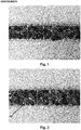
- FIG. 1 shows a photographic representation of a decorative element of the prior art, in which a plurality of gemstones 3 are held in a disordered form of an adhesive layer 2 on a support body 1, wherein the support body 1 is a cylindrical tube with a diameter of 3 mm.
- the gemstones 3 are so-called double tips, which consist of a front 11 tapered to a tip and an opposite, also tapering to a tip 12 back.
- the gemstones are cut from a glass ball and have a length of 2 mm. In the area of the largest cross-sectional dimension, which is also 2 mm, the gems 3 are surrounded by a Rondiste.
- the adhesive layer 2 has a layer thickness of 0.3 mm before the embedding of the gemstones.
- FIG. 2 shows a decorative element 10 according to the invention.
- the support body 1 has the same dimensions as that of the decorative element according to FIG. 1 wherein the adhesive layer 2 is in the same thickness as in FIG Fig. 1 is distributed on the surface of the carrier body 1.
- the gems 3 correspond to those of the decorative element according to FIG. 1 , In contrast to the prior art ( Fig. 1 ), the gems 3 have been aligned such that their given by the line connecting the tips 11 and 12 longitudinal direction is no longer perpendicular to the surface of the carrier body 1 is arranged.
- FIG. 3 shows a perspective detail view of a decorative element according to the prior art.
- the tubular support body 1 is enveloped by a continuous and uniform adhesive layer 2, which holds the gems 3 in disorderly distribution.
- the gems are double tips with opposite tips 11 and 12. Due to the disorderly distribution results in an uncomfortable feeling and an increased risk of injury and the risk that gemstones 3 are dissolved out of the decorative element is large, especially if the support body is flexible and in use is bent.
- FIG. 4 shows a decorative element 10 according to the invention in a perspective detail view, wherein in turn on a tubular support body 1, a continuous and uniform adhesive layer 2 is arranged. More than 60% of the Gems 3 are aligned according to the invention and therefore provide a high degree of coverage with a smoother surface, which is accompanied by an improved feel and less risk of injury, for example in the case of a bracelet or a necklace. In addition, the risk of detachment of gems 3 from the decorative element 10 is significantly reduced.
- FIG. 5 a first process step of the method according to the invention is shown, wherein the surface of a tubular carrier body 1 is provided throughout with an adhesive layer 2, the thickness of which depends on the size of the carrier body 1 and on the size of the gemstones 3 to be applied.
- the layer thickness of the adhesive layer 2 is between 0.2 mm and 0.3 mm.
- heated, liquid hotmelt adhesive 2 is fed via a feed device 5 to an application nozzle 6, from which the most uniform possible application of adhesive is achieved on the surface of the carrier body 1 in order to achieve optimum embedding of the gems 3.
- FIG. 6 a further process step is shown in which the gems 3 are applied from a reservoir 8 in random distribution on the still heated adhesive layer 2.
- the application is carried out by sprinkling.
- the carrier body 1 is rotated about its longitudinal axis in order to achieve a more uniform covering of the gems 3.
- This type of application is particularly favorable for carrier bodies with a curved surface, for example a rope-shaped one.
- the adhesive 2 is no longer liquid, but still viscous to some extent in order to press the gems 3 in a further step in the adhesive layer 2 can.
- FIGS. 7a and 7b It is shown how the gems 3 are pressed with a printing device in the form of a punch 9 in the adhesive layer 2, wherein the orientation of the gems 3 is changed with respect to the surface of the carrier body 1 during the depression.
- the punch 9 consists of two opposite elastic plates 9a and 9b.
- the plates 9a, 9b still move towards one another in the heated state of the adhesive 2 in the direction of the carrier body 1, whereby pressure is exerted on the gems 3 and the gems 3 are embedded in the adhesive layer 2, whereby substantially all the gems 3 aligned and compacted be and take a position in which the height H of the gems 3 with respect to the surface of the carrier body 1 is low.
- the plates move 9a, 9b during the depression parallel to the surface of the carrier body 1, whereby the alignment of the gems 3 is further improved.
- both plates 9a, 9b move parallel to the surface of the carrier body 1, it being further provided that the two plates 9a, 9b are moved in opposite directions R, L. Further, the support body 1 can be rotated during the depression of the gems 3.
- Such a punch 9 is used in particular in carrier bodies 1 with a round cross section.
- FIG. 7b shows another embodiment of the punch 9, wherein two pairs of respective opposing plates 9a, 9b, 9c, 9d are provided which press the gems 3 in the adhesive layer 2 and thereby align.
- This stamp is used in particular in carrier bodies 1 with a rectangular cross section.
- FIG. 8a shows a cross-sectional view of a decorative element of the prior art in which the gems 3 are distributed randomly and therefore take various and randomly distributed layers with respect to the surface of the support body 1.
- the gems 3 correspond to those of Figures 1 and 2 ,
- gems 3 are in a maximum position 3b, in which they are aligned perpendicular to the surface of the support body relative to a tangent plane at the location of the gem 3 and thus occupy a maximum height Hmax.
- FIG. 8a shows decorative element 10.
- FIG. 9 shows an attempt to demonstrate the better durability of the gems 3 in a decorative element 10 according to the invention in a tape test to check the adhesion of the gems 3, a strip of tape 14 type 3M VHB TM Tape 4910F Acrylic Foam of about 7 cm in length on a clean area of the decorative element 10, which is free of impurities, glued and peeled off the protective film of the adhesive tape 14. Subsequently, pressure is applied to the decorative element for a few seconds. Thereafter, the decorative element 10 is withdrawn at an angle of about 90 ° with a quick movement of the tape. To check the adhesion of the gems 3 is checked how many gems 3 adhere to the tape 14 after removal of the decorative element. As FIG.
- Fig. 10 shows a schematic representation of an enlarged section of the in Figure 8a illustrated decorative element.
- the gemstones are double tips, the front and rear converge to the tips 11 and 12 and are separated by a Rondiste 13.
- the front and the back are the same and faceted.
- the left upper gemstone 3 is located in the minimum position 3a, in which the front or rear side rests with the lateral boundary line on the outer surface of the carrier body 1.
- the height Hmin is given by the maximum of all normal distances of the gemstone with respect to the surface of the carrier body 1. Since it is a hollow cylinder in the illustrated carrier body 1, the normal distance refers to a tangential plane of the surface of the carrier body 1. In the present case this tangential plane is arranged perpendicular to the plane of the drawing.
- the upper right gem 3 is located in the maximum position 3b, in which the given by the line connecting the tips 11 and 12 longitudinal direction of the gem 3 is arranged perpendicular to the surface of the carrier body 1.
- the height H of the gemstone is the maximum height Hmax.
- the broken line represents the arithmetic mean H 'of the maximum height Hmax and the minimum height Hmin.
- at least more than 60% of the gems 3 are in a position 3c in which the height H is less than or equal to the arithmetic mean H' ,
Description
Die Erfindung betrifft ein dekoratives Element umfassend einen länglichen Trägerkörper und eine Vielzahl von, insbesondere facettierten, Schmucksteinen auf einer Klebstoffschicht auf dem Trägerkörper, wobei für jeden der Schmucksteine eine Minimallage und eine Maximallage existiert.The invention relates to a decorative element comprising an elongate carrier body and a plurality of, in particular faceted, gemstones on an adhesive layer on the carrier body, wherein for each of the gemstones a minimum position and a maximum position exists.
Die Erfindung betrifft weiterhin ein Verfahren zur Herstellung eines dekorativen Elements mit einem länglichen Trägerkörper und einer Vielzahl von auf dem Trägerkörper angeordneten Schmucksteinen umfassend die Schritte des Aufbringens einer Schicht Klebstoff auf die Oberfläche des Trägerkörpers und des Verteilens einer Vielzahl von Schmucksteinen auf der Oberfläche des Trägerkörpers.The invention further relates to a method for producing a decorative element with an elongate carrier body and a plurality of arranged on the support body gemstones comprising the steps of applying a layer of adhesive on the surface of the carrier body and distributing a plurality of gemstones on the surface of the carrier body.
Die erfindungsgemäßen dekorativen Elemente sind für die Herstellung verschiedenster Modeaccessoires und Schmuckstücke geeignet.The decorative elements of the invention are suitable for the production of various fashion accessories and jewelry.
In der Mode- und Designindustrie ist es gängig, Bekleidungsstücke, Handtaschen oder andere Accessoires mit Schmucksteinen zu verzieren. Wesentlich für das Aufbringen der Schmucksteine ist es, zumindest einen Teil der Schmucksteinoberfläche mit Klebstoff zu versehen und die Schmucksteine direkt zu applizieren. Will man allerdings großflächige Bereiche mit einer Vielzahl von Schmucksteinen versehen oder sind die Schmucksteine sehr klein und unhandlich, ist es äußerst umständlich und auch kostspielig, die Schmucksteine manuell, beispielsweise mit flüssigem Schmelzklebstoff, zu beschichten und am gewünschten Ort zu befestigen.In the fashion and design industry it is common to adorn garments, handbags or other accessories with gemstones. Essential for the application of the gemstones is to provide at least a portion of the gemstone surface with adhesive and apply the gems directly. However, if you want to provide large areas with a variety of gems or the gems are very small and unwieldy, it is extremely cumbersome and costly, the gemstones manually, for example, with liquid hot melt adhesive to coat and secure the desired location.
Zur Vermeidung dieser Problematik ist es bekannt, die Schmucksteine zuerst an einem Übertragungsmedium zu befestigen und dieses dann auf einem Kleidungsstück oder Modeaccessoire anzubringen. In der
In der
In
Der Erfindung liegt die Aufgabe zugrunde, ein dekoratives Element bereitzustellen, welches eine Vielzahl von Schmucksteinen, die von einer Klebstoffschicht gehalten werden, umfasst, und welches die oben erwähnten Nachteile vermeidet und den Anwendungsbereich der obigen Erfindungen erweitert. Ein weiterer Gegenstand der Erfindung betrifft ein Herstellungsverfahren für das erfindungsgemäße dekorative Element.The invention has for its object to provide a decorative element comprising a plurality of gemstones, which are held by an adhesive layer, and which avoids the disadvantages mentioned above and extends the scope of the above inventions. Another object of the invention relates to a production process for the decorative element according to the invention.
Die Aufgabe wird gelöst durch ein dekoratives Element mit den Merkmalen des Anspruchs 1 bzw. den Unteransprüchen und durch ein Verfahren mit den Merkmalen des Anspruchs 11 bzw. den Unteransprüchen.The object is achieved by a decorative element having the features of
Für jeden der Vielzahl an Schmucksteinen, die von einer auf dem länglichen Trägerköper verteilten Klebstoffschicht gehalten werden, gibt es eine Minimallage Hmin und eine Maximallage Hmax. In der Minimallage Hmin ist die Höhe des Schmucksteins relativ zur Oberfläche des Trägerkörpers minimal während in der Maximallage Hmax die Höhe des Schmucksteins relativ zur Oberfläche des Trägerkörpers maximal ist. Bei nicht kugelsymmetrischen Schmucksteinen sind die Minimallage und die Maximallage voneinander verschieden. Unter der Höhe ist dabei der größte Abstand des Schmucksteins von der Oberfläche des Trägerkörpers zu verstehen, also das Maximum aller Normalabstände aller Punkte des Schmucksteins. Im Falle einer gewölbten Oberfläche wie zum Beispiel der Mantelfläche eines Zylinders bezieht sich die Höhe des Schmuckteins relativ zur Oberfläche des Trägerkörpers auf eine Tangentialebene, die in jenem Punkt an die Oberfläche des Trägerkörpers gelegt wird, in dem der Schmuckstein den Trägerkörper berührt oder diesem am nächsten kommt.For each of the plurality of gemstones held by an adhesive layer distributed on the elongate carrier body, there is a minimum position Hmin and a maximum position Hmax. In the minimum position Hmin, the height of the gemstone is minimal relative to the surface of the carrier body, while in the maximum position Hmax the height of the gemstone is maximal relative to the surface of the carrier body. For non-spherically symmetric gemstones, the minimum position and the maximum position are different. Under the height is the largest distance of the gemstone from the surface of the carrier body to understand, so the maximum of all normal distances of all points of the gem. In the case of a curved surface such as the surface of a cylinder, the height of the jewelery relative to the surface of the support body refers to a tangential plane which is applied to the surface of the support body at that point where the gem touches or is closest to the support body comes.
Verfügen die Schmucksteine über eine Längsrichtung, in welcher die Schmucksteine die größte Ausdehnung aufweisen, so ist die Maximallage jene Lage, in der die Längsrichtung senkrecht zur Oberfläche des Trägerkörpers angeordnet ist. In der Minimallage ist die Längsrichtung in einem gewissen, von 90° verschiedenen Winkel zur Oberfläche des Trägerkörpers geneigt, wobei sich im Falle einer gewölbten Oberfläche dieser Winkel auf eine Tangentialebene bezieht, die in jenem Punkt an die Oberfläche des Trägerkörpers gelegt wird, in dem der Schmuckstein den Trägerkörper berührt oder diesem am nächsten kommt.If the gemstones have a longitudinal direction in which the gemstones have the greatest extent, then the maximum position is that position in which the longitudinal direction is arranged perpendicular to the surface of the carrier body. In the minimal position, the longitudinal direction is inclined at a certain angle different from 90 ° to the surface of the carrier body, wherein in the case of a curved surface, this angle refers to a tangential plane which is placed at that point on the surface of the carrier body, in which Gemstone touches the carrier body or comes closest to this.
Beim Trägerkörper handelt es sich um einen länglichen Körper, dessen Längserstreckung um ein Vielfaches größer als sein Querschnittsumfang ist. Dabei kann es sich beim länglichen Trägerkörper um einen wenigstens annähernd zylinderförmigen oder prismatischen Körper handeln, wobei insbesondere zylinderförmige Körper mit rundem Querschnitt und prismatische Körper mit rechteckigen, quadratischen oder dreieckigen Grundflächen vorgesehen sein können. Der Trägerkörper kann ferner gerade oder gebogen ausgebildet sein. Insbesondere kann derTrägerkörperflexibel und/oder hohl ausgebildet sein. Im Falle eines flexiblen und hohlen Trägerkörpers handelt es sich um einen schlauchförmigen Trägerkörper. Auch Trägerkörper in Form eines Seiles oder eines Flachbandes sind möglich.The carrier body is an elongated body whose longitudinal extent is many times greater than its cross-sectional circumference. In this case, the elongated carrier body may be an at least approximately cylindrical or prismatic body, wherein in particular cylindrical bodies with a round cross section and prismatic bodies with rectangular, square or triangular base surfaces may be provided. The carrier body may also be formed straight or curved. In particular, the carrier body may be flexible and / or hollow. In the case of a flexible and hollow carrier body is a tubular carrier body. Also carrier body in the form of a rope or a flat band are possible.
Der Trägerkörper selbst kann aus Kunststoff, insbesondere einem elastischen Kunststoff, hergestellt sein. Grundsätzlich ist das Material des Trägerkörpers nicht limitiert. Möglich sind beispielsweise auch Trägerkörper aus Metall, Holz und dergleichen mehr.The carrier body itself can be made of plastic, in particular an elastic plastic. In principle, the material of the carrier body is not limited. Also possible, for example, carrier body made of metal, wood and the like.
Indem sich mehr als 60% aller Schmucksteine in einer Lage befinden, in welcher die Höhe des Schmucksteins relativ zur Oberfläche des Trägerkörpers kleiner als oder gleich dem arithmetischem Mittel der minimalen Höhe Hmin und der maximalen Höhe Hmax ist, ist ein hoher Bedeckungsgrad des Trägerkörpers mit Schmucksteinen möglich. Die erfindungsgemäße Lage der Schmucksteine entspricht einer Schmucksteinausrichtung am Trägerkörper. Die Längsrichtung (vide supra) eines Schmucksteins schließt dabei mit der Oberfläche des Trägerkörpers einen Winkel ein, der unterhalb eines Grenzwerts liegt. Erfindungsgemäß bevorzugt beträgt der Grenzwert des Winkels der Längsachse weniger als 80°, bevorzugt weniger als 70° und ganz besonders bevorzugt weniger als 60°.By having more than 60% of all the gems in a position in which the height of the gem relative to the surface of the substrate is less than or equal to the arithmetic mean of the minimum height Hmin and the maximum height Hmax, a high degree of coverage of the substrate with gemstones possible. The inventive position of the gems corresponds to a gemstone alignment on the carrier body. The longitudinal direction (vide supra) of a gemstone encloses with the surface of the support body at an angle which is below a limit. According to the invention, the limit value of the angle of the longitudinal axis is preferably less than 80 °, preferably less than 70 ° and very particularly preferably less than 60 °.
Der hohe Bedeckungsgrad ergibt sich in Folge der ausgerichteten Schmucksteine, wobei die Klebstoffschicht zwischen den Schmucksteinen aufgrund des hohen Bedeckungsgrades nicht mehr oder nur noch kaum zu erkennen ist. Dies gilt insbesondere bei Trägerkörpern mit gewölbter Oberfläche, wie zum Beispiel bei Trägerkörpern mit rundem Querschnitt. Durch die Ausrichtung der Schmucksteine und die daraus resultierende erhöhte Bedeckung ist eine Glättung der Oberfläche mit reduzierter Oberflächenrauheit aufgrund einer verminderten mittleren Rauheit verbunden. Dies wird als ästhetisch ansprechend angesehen und ergibt ein verbessertes Tragegefühl sowie ein vermindertes Verletzungsrisiko, für den Fall, dass das dekorative Element am Körper getragen wird, beispielsweise als Armband oder als Halskette. Zudem hat sich herausgestellt, dass das Herauslösen von Schmucksteinen bei erfindungsgemäßen dekorativen Elementen reduziert ist. Dies gilt insbesondere bei flexiblen Trägerkörpern.The high degree of coverage results as a result of the aligned gemstones, the adhesive layer between the gemstones is no longer or only hardly recognizable due to the high degree of coverage. This applies in particular to carrier bodies with a curved surface, such as, for example, carrier bodies with a round cross-section. Due to the orientation of the gems and the resulting increased coverage, smoothing of the surface is associated with reduced surface roughness due to reduced average roughness. This is considered aesthetically pleasing and results in an improved wearing comfort and a reduced risk of injury in the event that the decorative element is worn on the body, for example as a bracelet or as a necklace. In addition, it has been found that the detachment of gemstones is reduced in decorative elements according to the invention. This applies in particular to flexible support bodies.
Bei der Vielzahl von Schmucksteinen kann es sich um gleichartige Schmucksteine gleicher Größe handeln. Möglich ist es aber auch, verschiedenartige Schmucksteine zu verwenden, insbesondere dann, wenn die verschiedenartigen Schmucksteine in ihrer Maximallage zumindest annähernd dieselbe maximale Höhe einnehmen, wodurch auch bei unterschiedlichen Schmucksteinen eine sehr glatte Oberfläche entstehen kann.The large number of gemstones can be identical gemstones of the same size. But it is also possible to use different types of gemstones, especially when the various gems in their maximum position take at least approximately the same maximum height, whereby even with different gemstones a very smooth surface can arise.
Weitere vorteilhafte Ausführungen der Erfindung sind in den abhängigen Ansprüchen definiert.Further advantageous embodiments of the invention are defined in the dependent claims.
In einer Ausführungsform werden mehr als 70%, bevorzugt mehr als 80% und ganz bevorzugt mehr als 90%, aller Schmucksteine in einer Lage am Trägerkörper gehalten, in welcher die Höhe des Schmucksteins relativ zur Oberfläche des Trägerkörpers kleiner als oder gleich dem arithmetischen Mittel der minimalen Höhe und der maximalen Höhe ist.In one embodiment, more than 70%, preferably more than 80%, and more preferably more than 90%, of all the gems are held in a position on the carrier body in which the height of the gem relative to the surface of the carrier body is less than or equal to the arithmetic mean of minimum height and maximum height.
In einer Ausführungsform werden im Wesentlichen alle Schmucksteine in einer Lage am Trägerkörper gehalten, in welcher die Höhe des Schmucksteins relativ zur Oberfläche des Trägerkörpers kleiner als oder gleich dem arithmetischen Mittel der minimalen Höhe und der maximalen Höhe ist. Dabei bedeutet das Merkmal "im Wesentlichen alle Schmucksteine", dass eine 2-Sigma-Umgebung des Mittelwerts der Höhen der Schmucksteine unterhalb des arithmetischen Mittels der minimalen Höhe und der maximalen Höhe liegt, bzw. dass eine 2-Sigma-Umgebung des Mittelwerts der Winkel der Längsrichtungen der Schmucksteine unterhalb dem von der Geometrie der Schmucksteine abhängigen Grenzwert liegt.In one embodiment, substantially all of the gems are held in a position on the support body in which the height of the gem relative to the surface of the support body is less than or equal to the arithmetic mean of the minimum height and the maximum height. In this case, the feature "essentially all the gems" means that a 2-sigma environment of the mean value of the heights of the gems is below the arithmetic mean of the minimum height and the maximum height, or that a 2 sigma environment of the mean value of the angles the longitudinal directions of the gems below the dependent on the geometry of the gems limit.
In einer Ausführungsform der Erfindung weist die Klebstoffschicht eine Schichtdicke zwischen 5% und 60%, vorzugsweise zwischen 10% und 40%, und besonders bevorzugt zwischen 15% und 20%, der maximalen Höhe der Schmucksteine auf. Dabei bezieht sich die Schichtdicke auf den Zustand vor dem Einbetten der Schmucksteine. Die Art des Klebstoffs ist prinzipiell nicht limitiert. Insbesondere sind alle Klebstoffe geeignet, die bei Raumtemperatur fest sind und bei einer Erwärmung auf ca. 70° erweichen. Bevorzugt werden erfindungsgemäß Thermoplaste, insbesondere Schmelzklebestoffe. Thermoplastische Polymere erweichen beim Erwärmen zu viskosen Flüssigkeiten und verfestigen sich beim Abkühlen. Besonders bevorzugt sind reaktive Schmelzklebstoffe, die in Bezug auf Verarbeitungs- und Abbindeeigenschaften vorteilhaft sind. Grundsätzlich sind aber auch Klebstoffe, ausgewählt aus der Gruppe der Duroplaste, möglich. Bevorzugt ist vorgesehen, den Klebstoff durchgängig auf der gesamten Oberfläche des Trägerkörpers zu verteilen.In one embodiment of the invention, the adhesive layer has a layer thickness between 5% and 60%, preferably between 10% and 40%, and particularly preferably between 15% and 20%, of the maximum height of the gemstones. The layer thickness refers to the state before embedding the gemstones. The type of adhesive is not limited in principle. In particular, all adhesives are suitable which are solid at room temperature and soften when heated to about 70 °. According to the invention, thermoplastics, in particular hotmelt adhesives, are preferred. Thermoplastic polymers soften when heated to viscous liquids and solidify on cooling. Particularly preferred are reactive hot melt adhesives, which are advantageous in terms of processing and setting properties. In principle, however, adhesives selected from the group of thermosetting plastics are also possible. It is preferably provided to distribute the adhesive throughout the entire surface of the carrier body.
In einer Ausführungsform der Erfindung ist der Trägerkörper aus einem flexiblen Material, vorzugsweise einem Kunststoff hergestellt, wobei der Trägerkörper hohl sein kann. Ein Beispiel eines flexiblen und hohlen Trägerkörpers im Sinne der Erfindung ist ein biegbarer Schlauch. Die Schmucksteine können aus Glas, vorzugsweise aus Kristallglas hergestellt sein. Unter Kristallglas soll dabei Glas verstanden werden, welches unter die Richtlinie des Rates der Europäischen Gemeinschaften 69/493/EWG fällt. Dekorative Elemente mit solchen Trägerkörpern und Schmucksteinen sind extrem vielfältig einsetzbar. Lediglich exemplarisch sei die Verwendung als Armbänder und Halsketten oder als Griffe für Handtaschen erwähnt.In one embodiment of the invention, the carrier body is made of a flexible material, preferably a plastic, wherein the carrier body may be hollow. An example of a flexible and hollow support body according to the invention is a flexible hose. The gemstones can be made of glass, preferably made of crystal glass. Crystal glass is understood to mean glass which falls within the scope of Council Directive 69/493 / EEC. Decorative elements with such bodies and gemstones are extremely versatile. Merely by way of example, the use as bracelets and necklaces or as handles for handbags mentioned.
In einer weiteren Ausführungsform der Erfindung liegt die Größe der Schmucksteine unter 10 mm, vorzugsweise zwischen 1 mm und 6 mm, und besonders bevorzugt bei etwa 2 mm. Dabei ist die Größe der Schmucksteine definiert durch deren größte Querschnittsabmessung. Bei einem chatonförmigen Schmuckstein mit einer zu einer Spitze zusammenlaufenden Rückseite und einer von einer ebenen Tafel begrenzten Vorderseite ist die größte Querschnittsabmessung in der Trennfläche zwischen der Vorderseite und der Rückseite angeordnet. Dies gilt auch bei Schmucksteinen mit einer zu einer Spitze zusammenlaufenden Vorderseite und einer zu einer Spitze zusammenlaufenden Rückseite. Bei Doppelspitzen ist aufgrund des Fertigungsprozesses die Querschnittsabmessung meist gleich groß wie die Längserstreckung. Bei Schmucksteinen, deren Vorderseite mit einer unsymmetrischen Querschnittsfläche von der Rückseite getrennt wird, ist die Größe des Schmucksteines die maximale Erstreckung der Querschnittsfläche. Ein Vorteil des erfindungsgemäßen Verfahrens liegt darin, dass es insbesondere für kleine Schmucksteine herangezogen werden kann.In a further embodiment of the invention, the size of the gems is less than 10 mm, preferably between 1 mm and 6 mm, and particularly preferably about 2 mm. The size of the gems is defined by their largest cross-sectional dimension. In the case of a chaton-shaped gemstone having a back side converging to a tip and a front side delimited by a flat plate, the largest cross-sectional dimension is disposed in the interface between the front side and the back side. This also applies to gemstones with a converging to a tip front and a converging to a tip back. In the case of double tips, the cross-sectional dimension is usually the same as the longitudinal extent due to the manufacturing process. For gemstones whose front is separated with an asymmetrical cross-sectional area of the back, the size of the gemstone is the maximum extent of the cross-sectional area. An advantage of the method according to the invention is that it can be used in particular for small gemstones.
Die Schmucksteine können eine sich zu einer Spitze verjüngende Vorderseite und eine gegenüberliegende, sich zu einer Spitze verjüngende Rückseite aufweisen, ähnlich einer doppelseitigen Pyramide. Derartige Schmucksteine werden häufig Doppelspitzen oder Doppelchatons genannt, wenn die Vorderseite und die Rückseite gleich ausgebildet sind. Die Längsrichtung derartiger Schmucksteine ist durch die Verbindungslinie der zwei Spitzen gegeben.The gemstones may have a tip-tapering face and an opposite tip-tapering face, similar to a double-sided pyramid. Such gems are often called double tips or Doppelchatons when the front and the back are the same. The longitudinal direction of such gems is given by the connecting line of the two peaks.
Neben Doppelspitzen weisen auch chatonförmige Schmucksteine eine sich zu einer Spitze verjüngende Rückseite und eine sich verjüngende Vorderseite auf, die allerdings durch eine ebene Tafel abgeschlossen ist. Bei Schmucksteinen mit einer sich verjüngenden Rückseite und einer sich verjüngenden Vorderseite ist der Bereich zwischen Vorderseite und Rückseite der Bereich der größten Querschnittsfläche und die Längsrichtung der Schmucksteine ist senkrecht auf diese Querschnittsfläche angeordnet. Die Querschnittsfläche kann von einer Kante aber auch von einem flächigen Rand, der sogenannte Rondiste umrandet sein. Im Falle einer Rondiste ergeben sich ein besonders angenehmes Tragegefühl und ein weiter verringertes Verletzungsrisiko. Dies gilt insbesondere bei Schmucksteinen, bei denen die Vorderseite und die Rückseite facettiert geschliffen sind, während die Rondiste nicht geschliffen ist.In addition to double points, chaton-shaped gemstones also have a back that tapers to a point and a tapered front, which, however, is closed off by a flat board. In the case of gemstones having a tapered back surface and a tapered front surface, the region between the front surface and the back surface is the region of the largest cross-sectional area, and the longitudinal direction of the gemstones is perpendicular to this cross-sectional surface. The cross-sectional area may be bordered by an edge but also by a flat edge, the so-called Rondiste. In the case of a Rondiste arise a particularly comfortable to wear and a further reduced risk of injury. This is especially true for gemstones, in which the front and the back are cut faceted, while the Rondiste is not honed.
In einer Ausführungsform der Erfindung sind zusätzlich zu den obigen Schmucksteinen eine Vielzahl von im Wesentlichen kugelförmigen Dekorelementen, vorzugsweise Glaskugeln, auf dem Trägerkörper angeordnet. Derartige Dekorelemente weisen stets nur eine Höhe und somit keine von der minimalen Höhe verschiedene maximale Höhe auf. Im Zusammenhang mit den Schmucksteinen ergeben sich dabei optisch reizvolle Effekte.In one embodiment of the invention, in addition to the above gemstones, a plurality of substantially spherical decorative elements, preferably glass spheres, are arranged on the carrier body. Such decorative elements always have only one height and thus no maximum height different from the minimum height. In connection with the gemstones arise while visually attractive effects.
Im erfindungsgemäßen Verfahren werden die Schmucksteine mit einer Druckvorrichtung in die Klebstoffschicht gedrückt, wobei die Ausrichtung der Schmucksteine in Bezug auf die Oberfläche des Trägerkörpers während des Eindrückens erfolgt. Die Druckvorrichtung führt während des Eindrückens der Schmucksteine eine Bewegung parallel zur Oberfläche des Trägerkörpers aus. Dadurch wird das Ausrichten der Schmucksteine verbessert.In the method according to the invention the gems are pressed with a printing device in the adhesive layer, wherein the alignment of the gems takes place with respect to the surface of the carrier body during the indentation. The printing device performs during the depression of the gems a movement parallel to the surface of the carrier body. This improves the alignment of the gems.
Bei der Druckvorrichtung kann es sich um einen Stempel mit einer oder mehreren Druckplatten handeln, welche die Schmucksteine in den Klebstoff drücken, oder um eine Walze, mit der ebenfalls die Schmucksteine in die Klebstoffschicht gedrückt werden können. Die Druckvorrichtung kann dabei in einer Ausführungsform während des Eindrückens parallel zur Oberfläche des Trägerkörpers bewegt werden. Bei einer Walze ergibt sich die Bewegung parallel zur Oberfläche des Trägerkörpers durch die Rotation der Walze. Die Parallelität bezieht sich in beiden Fällen auf jenen Bereich des Trägerkörpers, in dem die Schmucksteine von der Druckvorrichtung in die Klebstoffschicht gedrückt werden. Dabei erfolgt die Bewegung der Druckvorrichtung parallel zu einer Tangentialebene, die an jenen Bereich der Oberfläche des Trägerkörpers gelegt wird, in dem auf die Schmucksteine von der Druckvorrichtung Druck ausgeübt wird.The printing device can be a stamp with one or more printing plates, which press the gemstones into the adhesive, or a roller with which the gemstones can likewise be pressed into the adhesive layer. In one embodiment, the printing device can be moved parallel to the surface of the carrier body during the depression. In a roller, the movement results parallel to the surface of the carrier body by the rotation of the roller. The parallelism refers in both cases to that area of the carrier body in which the gemstones be pressed by the printing device in the adhesive layer. In this case, the movement of the printing device takes place parallel to a tangential plane which is placed on that region of the surface of the carrier body, in which pressure is exerted on the gemstones by the printing device.
In einer bevorzugten Ausführungsform besteht der Stempel aus zumindest zwei parallel angeordneten Platten, mit denen die Schmucksteine in die Klebstoffschicht gedrückt werden. Dies ist insbesondere dann von Vorteil wenn der Trägerkörper an gegenüberliegenden Bereichen mit Schmucksteinen bedeckt werden soll oder wenn es sich um einen Trägerkörper mit rundem Querschnitt handelt. Dabei können die gegenüberliegenden Platten des Stempels während des Eindrückens der Schmucksteine in entgegengesetzte Richtungen parallel zur Oberfläche des Trägerkörpers bewegt werden. Ferner kann vorgesehen sein, den Trägerkörper während des Eindrückens der Schmucksteine zu rotieren.In a preferred embodiment, the punch consists of at least two parallel plates, with which the gems are pressed into the adhesive layer. This is particularly advantageous if the carrier body is to be covered at opposite areas with gemstones or if it is a carrier body with a round cross-section. In this case, the opposing plates of the stamp can be moved during the depression of the gems in opposite directions parallel to the surface of the carrier body. Furthermore, it can be provided to rotate the carrier body during the indentation of the gemstones.
Weitere Einzelheiten und Vorteile der vorliegenden Erfindung werden anhand der Figurenbeschreibung unter Bezugnahme auf die Zeichnungen im Folgenden näher erläutert. Darin zeigt:
-
Fig. 1 eine fotografische Darstellung eines dekorativen Elementes nach dem Stand der Technik, -
Fig. 2 eine fotografische Darstellung eines erfindungsgemäßen dekorativen Elementes, -
Fig. 3 eine perspektivische Detailansicht eines dekorativen Elementes des Standes der Technik, -
Fig. 4 eine perspektivische Detailansicht eines erfindungsgemäßen dekorativen Elementes, -
Fig. 5 eine schematische Ansicht eines ersten Verfahrensschrittes des erfindungsgemäßen Verfahrens, -
Fig. 6 eine schematische Ansicht eines zweiten Verfahrensschrittes des erfindungsgemäßen Verfahrens, -
Fig. 7a und 7b schematische Ansichten eines dritten Verfahrensschrittes des erfindungsgemäßen Verfahrens mit unterschiedlichen Stempeln, -
Fig. 8a und 8b Querschnittsdarstellungen eines dekorativen Elementes des Standes der Technik und eines erfindungsgemäßen dekorativen Elementes, -
Fig. 9 eine fotografische Darstellung zur Durchführung eines Versuchs über die Festigkeit der Verbindung zwischen den Schmucksteinen und der Klebstoffschicht, und -
Fig. 10 eine schematische Darstellung zur Erläuterung der minimalen Höhe und der maximalen Höhe.
-
Fig. 1 a photographic representation of a decorative element according to the prior art, -
Fig. 2 a photographic representation of a decorative element according to the invention, -
Fig. 3 a detailed perspective view of a decorative element of the prior art, -
Fig. 4 a detailed perspective view of a decorative element according to the invention, -
Fig. 5 a schematic view of a first process step of the method according to the invention, -
Fig. 6 a schematic view of a second process step of the method according to the invention, -
Fig. 7a and 7b schematic views of a third process step of the method according to the invention with different punches, -
Fig. 8a and 8b Cross-sectional views of a decorative element of the prior art and a decorative element according to the invention, -
Fig. 9 a photographic representation for carrying out an experiment on the strength of the connection between the gemstones and the adhesive layer, and -
Fig. 10 a schematic representation for explaining the minimum height and the maximum height.
In
Über eine Zuführvorrichtung 5 wird in diesem Ausführungsbeispiel erwärmter, flüssiger Schmelzklebestoff 2 zu einer Auftragsdüse 6 geführt, von der ein möglichst gleichmäßiger Klebstoffauftrag auf der Oberfläche des Trägerkörpers 1 erzielt wird, um eine optimale Einbettung der Schmucksteine 3 zu erreichen.In this exemplary embodiment, heated,
In
In den
In der
Nachdem die Schmucksteine 3 unter Druck ausgerichtet worden sind, ergibt sich das in der Querschnittsdarstellung gemäß
Claims (14)
- Decorative element, comprising- an elongate carrier body (1), and- a plurality of gemstones (3), in particular faceted gemstones,on an adhesive layer (2) on the carrier body (1), wherein for each of the gemstones (3) there is a minimum position (3a) and a maximum position (3b) relative to the surface of the carrier body (1), characterised in that more than 60% of the gemstones (3) are held in a position (3c) in which the height (H) of the gemstone (3) relative to the surface of the carrier body (1) is smaller than or equal to the arithmetic mean of the height (Hmin) in the minimum position (3a) and the height (Hmax) in the maximum position (3b).
- Decorative element according to claim 1, wherein more than 70%, preferably more than 80% and most preferably more than 90%, of the gemstones (3) are held in a position (3c) in which the height (H) of the gemstone (3) relative to the surface of the carrier body (1) is smaller than or equal to the arithmetic mean of the height (Hmin) in the minimum position (3a) and the height (Hmax) in the maximum position (3b).
- Decorative element according to claim 1 or 2, wherein the adhesive layer (2), before the gemstones (3) are embedded therein, has a layer thickness of from 5% to 60%, preferably from 10% to 40% and particularly preferably from 15% to 20%, based on the height (Hmax) of the gemstones (3) in the maximum position (3b).
- Decorative element according to at least one of claims 1 to 3, wherein the carrier body (1) is made of a flexible material, preferably a plastics material, and/or the gemstones (3) are made of glass, preferably crystal glass.
- Decorative element according to at least one of claims 1 to 4, wherein the carrier body (1) is hollow.
- Decorative element according to at least one of claims 1 to 5, wherein the gemstones (3) have a front side which tapers to a point (11) and an opposite rear side which tapers to a point (12).
- Decorative element according to claim 6, wherein the rear side is separated from the front side by a girdle (13).
- Decorative element according to at least one of claims 1 to 7, wherein the size of the gemstones (3) is smaller than 10 mm, preferably is between 1 mm and 6 mm, and particularly preferably is approximately 2 mm.
- Decorative element according to at least one of claims 1 to 8, wherein, in addition to the gemstones (3), spherical decorative elements, preferably glass beads, are contained in the adhesive layer (2).
- Decorative element according to at least one of claims 1 to 9, wherein the adhesive is selected from the group of the thermoplastics.
- Process for producing a decorative element (10) having an elongate carrier body (1) and a plurality of gemstones (3) arranged on the carrier body (1), in particular according to at least one of claims 1 to 10, comprising the following steps:(a) applying an adhesive layer (2) to the surface of the carrier body (1),(b) distributing a plurality of gemstones (3) on the surface of the carrier body (1),wherein the gemstones (3) are pressed into the adhesive layer (2) by a pressure device, whereby the gemstones (3) are oriented relative to the surface of the carrier body (1), characterised in that the pressure device performs a movement parallel to the surface of the carrier body (1) while the gemstones (3) are being pressed in.
- Process according to claim 11, wherein the pressure device comprises a stamp (9) consisting of at least two plates (9a, 9b), preferably resilient plates, which are arranged in parallel and by means of which the gemstones (3) are pressed into the adhesive layer (2).
- Process according to claim 12, wherein the parallel plates (9a, 9b) of the stamp (9) are moved in opposite directions (L, R) parallel to the surface of the carrier body (1) while the gemstones (3) are being pressed in.
- Process according to at least one of claims 11 to 13, wherein the carrier body (1) is rotated about its longitudinal axis while the gemstones (3) are being pressed in.
Priority Applications (7)
| Application Number | Priority Date | Filing Date | Title |
|---|---|---|---|
| ES16157633T ES2750568T3 (en) | 2016-02-26 | 2016-02-26 | Elongated decorative element with reduced surface roughness |
| EP16157633.5A EP3210490B1 (en) | 2016-02-26 | 2016-02-26 | Elongated decorative element with reduced surface roughness |
| PCT/EP2016/079109 WO2017144133A1 (en) | 2016-02-26 | 2016-11-29 | Elongated decorative element having a reduced surface roughness |
| US16/078,768 US10575606B2 (en) | 2016-02-26 | 2016-11-29 | Elongate decorative element with reduced surface roughness |
| TW105140420A TWI737657B (en) | 2016-02-26 | 2016-12-07 | Elongate decorative element with reduced surface roughness |
| CN201621436604.1U CN206718847U (en) | 2016-02-26 | 2016-12-23 | The elongated decoration element that surface roughness reduces |
| CN201611208866.7A CN107125861B (en) | 2016-02-26 | 2016-12-23 | Elongated decorative element with reduced surface roughness |
Applications Claiming Priority (1)
| Application Number | Priority Date | Filing Date | Title |
|---|---|---|---|
| EP16157633.5A EP3210490B1 (en) | 2016-02-26 | 2016-02-26 | Elongated decorative element with reduced surface roughness |
Publications (2)
| Publication Number | Publication Date |
|---|---|
| EP3210490A1 EP3210490A1 (en) | 2017-08-30 |
| EP3210490B1 true EP3210490B1 (en) | 2019-07-31 |
Family
ID=55451059
Family Applications (1)
| Application Number | Title | Priority Date | Filing Date |
|---|---|---|---|
| EP16157633.5A Active EP3210490B1 (en) | 2016-02-26 | 2016-02-26 | Elongated decorative element with reduced surface roughness |
Country Status (6)
| Country | Link |
|---|---|
| US (1) | US10575606B2 (en) |
| EP (1) | EP3210490B1 (en) |
| CN (2) | CN206718847U (en) |
| ES (1) | ES2750568T3 (en) |
| TW (1) | TWI737657B (en) |
| WO (1) | WO2017144133A1 (en) |
Families Citing this family (2)
| Publication number | Priority date | Publication date | Assignee | Title |
|---|---|---|---|---|
| ES2750568T3 (en) * | 2016-02-26 | 2020-03-26 | Swarovski D Kg | Elongated decorative element with reduced surface roughness |
| USD927188S1 (en) * | 2019-04-10 | 2021-08-10 | J. Choo Limited | Fashion ornament |
Family Cites Families (8)
| Publication number | Priority date | Publication date | Assignee | Title |
|---|---|---|---|---|
| DE4218498A1 (en) * | 1992-06-04 | 1993-12-09 | Zwiener Karin | Synthetic jewellery or ornamental stone mfr. - using heat activated adhesive layer contg. a heat resistant material for bonding to substrate |
| AT5316U1 (en) | 2001-08-08 | 2002-05-27 | Swarovski & Co | DEVICE FOR APPLYING GLASS ELEMENTS ON A BASE |
| JP2008290317A (en) * | 2007-05-23 | 2008-12-04 | Ko Pearl Co Ltd | Artistic decorating |
| CN102885441A (en) | 2007-08-01 | 2013-01-23 | 清原株式会社 | Rod-shaped body for decoration and manufacturing method thereof |
| AT10381U1 (en) | 2008-06-19 | 2009-02-15 | Swarovski & Co | LONG DECORATIVE ELEMENT |
| AT13397U1 (en) | 2012-07-02 | 2013-12-15 | Swarovski D Kg | Gemstone with arched rim |
| ES2750568T3 (en) | 2016-02-26 | 2020-03-26 | Swarovski D Kg | Elongated decorative element with reduced surface roughness |
| CN106363534B (en) | 2016-09-06 | 2019-05-03 | 老凤祥东莞珠宝首饰有限公司 | Jewellery blasting craft |
-
2016
- 2016-02-26 ES ES16157633T patent/ES2750568T3/en active Active
- 2016-02-26 EP EP16157633.5A patent/EP3210490B1/en active Active
- 2016-11-29 WO PCT/EP2016/079109 patent/WO2017144133A1/en active Application Filing
- 2016-11-29 US US16/078,768 patent/US10575606B2/en not_active Expired - Fee Related
- 2016-12-07 TW TW105140420A patent/TWI737657B/en active
- 2016-12-23 CN CN201621436604.1U patent/CN206718847U/en active Active
- 2016-12-23 CN CN201611208866.7A patent/CN107125861B/en active Active
Non-Patent Citations (1)
| Title |
|---|
| None * |
Also Published As
| Publication number | Publication date |
|---|---|
| US10575606B2 (en) | 2020-03-03 |
| WO2017144133A1 (en) | 2017-08-31 |
| TWI737657B (en) | 2021-09-01 |
| TW201729713A (en) | 2017-09-01 |
| CN206718847U (en) | 2017-12-08 |
| CN107125861A (en) | 2017-09-05 |
| EP3210490A1 (en) | 2017-08-30 |
| CN107125861B (en) | 2021-07-30 |
| ES2750568T3 (en) | 2020-03-26 |
| US20190125043A1 (en) | 2019-05-02 |
Similar Documents
| Publication | Publication Date | Title |
|---|---|---|
| DE2855426C2 (en) | Process for coating gemstones with a hot melt adhesive layer | |
| EP1387627B1 (en) | Method for producing a touch-and-close fastener element | |
| AT507129B1 (en) | METHOD FOR PRODUCING A JEWELRY STRUCTURE | |
| EP3210490B1 (en) | Elongated decorative element with reduced surface roughness | |
| WO2008119407A1 (en) | Method for the production of an adhesive closure device together with apparatus and adhesive closure device produced accordingly | |
| EP2135749A2 (en) | Elongated decorative element | |
| WO2003004186A1 (en) | Method for producing a metal sheet, metal sheet and device for structuring the surface of a metal sheet | |
| DE10161744A1 (en) | Cling type plastic fastener strip manufacture involves pin creation by compression of plastic strip into holes in a rubber cover on a metal roll then shaping of heads on pins | |
| WO1991006885A1 (en) | Spectacle frame | |
| EP3024351B1 (en) | Method for fastening precious stones | |
| DE102017209430A1 (en) | Multi-axis flexure member and method of making the same | |
| EP1867581A1 (en) | Package | |
| WO2010013122A2 (en) | Jewellery/decorative element | |
| EP1563755B1 (en) | Ring, particularly jewellery with a ring | |
| DE3701895C1 (en) | Apparatus for joining elements resting flat upon one another, for example metal sheets, by the joggling method | |
| DE102006032830A1 (en) | Device for transporting a material strand | |
| DE2940582C2 (en) | Method and device for coating elements for sorting, classifying and / or separating goods | |
| EP4065332A1 (en) | Endless belt and a method for producing same | |
| DE10143255A1 (en) | Adhesive adapter for dent removal device | |
| AT410900B (en) | METHOD FOR PRODUCING A STRUCTURED RUNNING FOR SLIDING DEVICES AND A STRUCTURED RUNNING PRODUCED BY THIS METHOD | |
| AT524459B1 (en) | Metal strip production by grinding | |
| AT12168U1 (en) | TRANSFER DEVICE FOR JEWELERY STONES | |
| AT13397U1 (en) | Gemstone with arched rim | |
| AT8572U1 (en) | COMPOSITION OF METALLIC PLATES | |
| DE202007005588U1 (en) | Heat-activated film with adhesive dots |
Legal Events
| Date | Code | Title | Description |
|---|---|---|---|
| PUAI | Public reference made under article 153(3) epc to a published international application that has entered the european phase |
Free format text: ORIGINAL CODE: 0009012 |
|
| STAA | Information on the status of an ep patent application or granted ep patent |
Free format text: STATUS: THE APPLICATION HAS BEEN PUBLISHED |
|
| AK | Designated contracting states |
Kind code of ref document: A1 Designated state(s): AL AT BE BG CH CY CZ DE DK EE ES FI FR GB GR HR HU IE IS IT LI LT LU LV MC MK MT NL NO PL PT RO RS SE SI SK SM TR |
|
| AX | Request for extension of the european patent |
Extension state: BA ME |
|
| STAA | Information on the status of an ep patent application or granted ep patent |
Free format text: STATUS: REQUEST FOR EXAMINATION WAS MADE |
|
| 17P | Request for examination filed |
Effective date: 20180222 |
|
| RBV | Designated contracting states (corrected) |
Designated state(s): AL AT BE BG CH CY CZ DE DK EE ES FI FR GB GR HR HU IE IS IT LI LT LU LV MC MK MT NL NO PL PT RO RS SE SI SK SM TR |
|
| GRAP | Despatch of communication of intention to grant a patent |
Free format text: ORIGINAL CODE: EPIDOSNIGR1 |
|
| STAA | Information on the status of an ep patent application or granted ep patent |
Free format text: STATUS: GRANT OF PATENT IS INTENDED |
|
| INTG | Intention to grant announced |
Effective date: 20190207 |
|
| GRAS | Grant fee paid |
Free format text: ORIGINAL CODE: EPIDOSNIGR3 |
|
| GRAA | (expected) grant |
Free format text: ORIGINAL CODE: 0009210 |
|
| STAA | Information on the status of an ep patent application or granted ep patent |
Free format text: STATUS: THE PATENT HAS BEEN GRANTED |
|
| AK | Designated contracting states |
Kind code of ref document: B1 Designated state(s): AL AT BE BG CH CY CZ DE DK EE ES FI FR GB GR HR HU IE IS IT LI LT LU LV MC MK MT NL NO PL PT RO RS SE SI SK SM TR |
|
| REG | Reference to a national code |
Ref country code: CH Ref legal event code: EP Ref country code: GB Ref legal event code: FG4D Free format text: NOT ENGLISH |
|
| REG | Reference to a national code |
Ref country code: DE Ref legal event code: R096 Ref document number: 502016005756 Country of ref document: DE |
|
| REG | Reference to a national code |
Ref country code: AT Ref legal event code: REF Ref document number: 1159986 Country of ref document: AT Kind code of ref document: T Effective date: 20190815 |
|
| REG | Reference to a national code |
Ref country code: IE Ref legal event code: FG4D Free format text: LANGUAGE OF EP DOCUMENT: GERMAN |
|
| REG | Reference to a national code |
Ref country code: NL Ref legal event code: MP Effective date: 20190731 |
|
| REG | Reference to a national code |
Ref country code: LT Ref legal event code: MG4D |
|
| PG25 | Lapsed in a contracting state [announced via postgrant information from national office to epo] |
Ref country code: NL Free format text: LAPSE BECAUSE OF FAILURE TO SUBMIT A TRANSLATION OF THE DESCRIPTION OR TO PAY THE FEE WITHIN THE PRESCRIBED TIME-LIMIT Effective date: 20190731 Ref country code: HR Free format text: LAPSE BECAUSE OF FAILURE TO SUBMIT A TRANSLATION OF THE DESCRIPTION OR TO PAY THE FEE WITHIN THE PRESCRIBED TIME-LIMIT Effective date: 20190731 Ref country code: BG Free format text: LAPSE BECAUSE OF FAILURE TO SUBMIT A TRANSLATION OF THE DESCRIPTION OR TO PAY THE FEE WITHIN THE PRESCRIBED TIME-LIMIT Effective date: 20191031 Ref country code: SE Free format text: LAPSE BECAUSE OF FAILURE TO SUBMIT A TRANSLATION OF THE DESCRIPTION OR TO PAY THE FEE WITHIN THE PRESCRIBED TIME-LIMIT Effective date: 20190731 Ref country code: LT Free format text: LAPSE BECAUSE OF FAILURE TO SUBMIT A TRANSLATION OF THE DESCRIPTION OR TO PAY THE FEE WITHIN THE PRESCRIBED TIME-LIMIT Effective date: 20190731 Ref country code: PT Free format text: LAPSE BECAUSE OF FAILURE TO SUBMIT A TRANSLATION OF THE DESCRIPTION OR TO PAY THE FEE WITHIN THE PRESCRIBED TIME-LIMIT Effective date: 20191202 Ref country code: FI Free format text: LAPSE BECAUSE OF FAILURE TO SUBMIT A TRANSLATION OF THE DESCRIPTION OR TO PAY THE FEE WITHIN THE PRESCRIBED TIME-LIMIT Effective date: 20190731 Ref country code: NO Free format text: LAPSE BECAUSE OF FAILURE TO SUBMIT A TRANSLATION OF THE DESCRIPTION OR TO PAY THE FEE WITHIN THE PRESCRIBED TIME-LIMIT Effective date: 20191031 |
|
| PG25 | Lapsed in a contracting state [announced via postgrant information from national office to epo] |
Ref country code: RS Free format text: LAPSE BECAUSE OF FAILURE TO SUBMIT A TRANSLATION OF THE DESCRIPTION OR TO PAY THE FEE WITHIN THE PRESCRIBED TIME-LIMIT Effective date: 20190731 Ref country code: GR Free format text: LAPSE BECAUSE OF FAILURE TO SUBMIT A TRANSLATION OF THE DESCRIPTION OR TO PAY THE FEE WITHIN THE PRESCRIBED TIME-LIMIT Effective date: 20191101 Ref country code: LV Free format text: LAPSE BECAUSE OF FAILURE TO SUBMIT A TRANSLATION OF THE DESCRIPTION OR TO PAY THE FEE WITHIN THE PRESCRIBED TIME-LIMIT Effective date: 20190731 Ref country code: AL Free format text: LAPSE BECAUSE OF FAILURE TO SUBMIT A TRANSLATION OF THE DESCRIPTION OR TO PAY THE FEE WITHIN THE PRESCRIBED TIME-LIMIT Effective date: 20190731 |
|
| REG | Reference to a national code |
Ref country code: ES Ref legal event code: FG2A Ref document number: 2750568 Country of ref document: ES Kind code of ref document: T3 Effective date: 20200326 |
|
| PG25 | Lapsed in a contracting state [announced via postgrant information from national office to epo] |
Ref country code: TR Free format text: LAPSE BECAUSE OF FAILURE TO SUBMIT A TRANSLATION OF THE DESCRIPTION OR TO PAY THE FEE WITHIN THE PRESCRIBED TIME-LIMIT Effective date: 20190731 |
|
| PG25 | Lapsed in a contracting state [announced via postgrant information from national office to epo] |
Ref country code: DK Free format text: LAPSE BECAUSE OF FAILURE TO SUBMIT A TRANSLATION OF THE DESCRIPTION OR TO PAY THE FEE WITHIN THE PRESCRIBED TIME-LIMIT Effective date: 20190731 Ref country code: EE Free format text: LAPSE BECAUSE OF FAILURE TO SUBMIT A TRANSLATION OF THE DESCRIPTION OR TO PAY THE FEE WITHIN THE PRESCRIBED TIME-LIMIT Effective date: 20190731 Ref country code: RO Free format text: LAPSE BECAUSE OF FAILURE TO SUBMIT A TRANSLATION OF THE DESCRIPTION OR TO PAY THE FEE WITHIN THE PRESCRIBED TIME-LIMIT Effective date: 20190731 Ref country code: PL Free format text: LAPSE BECAUSE OF FAILURE TO SUBMIT A TRANSLATION OF THE DESCRIPTION OR TO PAY THE FEE WITHIN THE PRESCRIBED TIME-LIMIT Effective date: 20190731 |
|
| PG25 | Lapsed in a contracting state [announced via postgrant information from national office to epo] |
Ref country code: SM Free format text: LAPSE BECAUSE OF FAILURE TO SUBMIT A TRANSLATION OF THE DESCRIPTION OR TO PAY THE FEE WITHIN THE PRESCRIBED TIME-LIMIT Effective date: 20190731 Ref country code: IS Free format text: LAPSE BECAUSE OF FAILURE TO SUBMIT A TRANSLATION OF THE DESCRIPTION OR TO PAY THE FEE WITHIN THE PRESCRIBED TIME-LIMIT Effective date: 20200224 Ref country code: SK Free format text: LAPSE BECAUSE OF FAILURE TO SUBMIT A TRANSLATION OF THE DESCRIPTION OR TO PAY THE FEE WITHIN THE PRESCRIBED TIME-LIMIT Effective date: 20190731 Ref country code: CZ Free format text: LAPSE BECAUSE OF FAILURE TO SUBMIT A TRANSLATION OF THE DESCRIPTION OR TO PAY THE FEE WITHIN THE PRESCRIBED TIME-LIMIT Effective date: 20190731 |
|
| REG | Reference to a national code |
Ref country code: DE Ref legal event code: R097 Ref document number: 502016005756 Country of ref document: DE |
|
| PLBE | No opposition filed within time limit |
Free format text: ORIGINAL CODE: 0009261 |
|
| STAA | Information on the status of an ep patent application or granted ep patent |
Free format text: STATUS: NO OPPOSITION FILED WITHIN TIME LIMIT |
|
| PG2D | Information on lapse in contracting state deleted |
Ref country code: IS |
|
| PG25 | Lapsed in a contracting state [announced via postgrant information from national office to epo] |
Ref country code: IS Free format text: LAPSE BECAUSE OF FAILURE TO SUBMIT A TRANSLATION OF THE DESCRIPTION OR TO PAY THE FEE WITHIN THE PRESCRIBED TIME-LIMIT Effective date: 20191030 |
|
| 26N | No opposition filed |
Effective date: 20200603 |
|
| PG25 | Lapsed in a contracting state [announced via postgrant information from national office to epo] |
Ref country code: SI Free format text: LAPSE BECAUSE OF FAILURE TO SUBMIT A TRANSLATION OF THE DESCRIPTION OR TO PAY THE FEE WITHIN THE PRESCRIBED TIME-LIMIT Effective date: 20190731 |
|
| REG | Reference to a national code |
Ref country code: CH Ref legal event code: PL |
|
| REG | Reference to a national code |
Ref country code: BE Ref legal event code: MM Effective date: 20200229 |
|
| PG25 | Lapsed in a contracting state [announced via postgrant information from national office to epo] |
Ref country code: MC Free format text: LAPSE BECAUSE OF FAILURE TO SUBMIT A TRANSLATION OF THE DESCRIPTION OR TO PAY THE FEE WITHIN THE PRESCRIBED TIME-LIMIT Effective date: 20190731 Ref country code: LU Free format text: LAPSE BECAUSE OF NON-PAYMENT OF DUE FEES Effective date: 20200226 |
|
| PG25 | Lapsed in a contracting state [announced via postgrant information from national office to epo] |
Ref country code: LI Free format text: LAPSE BECAUSE OF NON-PAYMENT OF DUE FEES Effective date: 20200229 Ref country code: CH Free format text: LAPSE BECAUSE OF NON-PAYMENT OF DUE FEES Effective date: 20200229 |
|
| PG25 | Lapsed in a contracting state [announced via postgrant information from national office to epo] |
Ref country code: IE Free format text: LAPSE BECAUSE OF NON-PAYMENT OF DUE FEES Effective date: 20200226 |
|
| PG25 | Lapsed in a contracting state [announced via postgrant information from national office to epo] |
Ref country code: BE Free format text: LAPSE BECAUSE OF NON-PAYMENT OF DUE FEES Effective date: 20200229 |
|
| PG25 | Lapsed in a contracting state [announced via postgrant information from national office to epo] |
Ref country code: MT Free format text: LAPSE BECAUSE OF FAILURE TO SUBMIT A TRANSLATION OF THE DESCRIPTION OR TO PAY THE FEE WITHIN THE PRESCRIBED TIME-LIMIT Effective date: 20190731 Ref country code: CY Free format text: LAPSE BECAUSE OF FAILURE TO SUBMIT A TRANSLATION OF THE DESCRIPTION OR TO PAY THE FEE WITHIN THE PRESCRIBED TIME-LIMIT Effective date: 20190731 |
|
| PG25 | Lapsed in a contracting state [announced via postgrant information from national office to epo] |
Ref country code: MK Free format text: LAPSE BECAUSE OF FAILURE TO SUBMIT A TRANSLATION OF THE DESCRIPTION OR TO PAY THE FEE WITHIN THE PRESCRIBED TIME-LIMIT Effective date: 20190731 |
|
| PGFP | Annual fee paid to national office [announced via postgrant information from national office to epo] |
Ref country code: FR Payment date: 20230217 Year of fee payment: 8 Ref country code: ES Payment date: 20230317 Year of fee payment: 8 Ref country code: AT Payment date: 20230215 Year of fee payment: 8 |
|
| PGFP | Annual fee paid to national office [announced via postgrant information from national office to epo] |
Ref country code: IT Payment date: 20230228 Year of fee payment: 8 Ref country code: GB Payment date: 20230221 Year of fee payment: 8 Ref country code: DE Payment date: 20230216 Year of fee payment: 8 |
|
| P01 | Opt-out of the competence of the unified patent court (upc) registered |
Effective date: 20230527 |