EP3210461A1 - Method for operating a cleaning device of a combine harvester - Google Patents
Method for operating a cleaning device of a combine harvester Download PDFInfo
- Publication number
- EP3210461A1 EP3210461A1 EP16202645.4A EP16202645A EP3210461A1 EP 3210461 A1 EP3210461 A1 EP 3210461A1 EP 16202645 A EP16202645 A EP 16202645A EP 3210461 A1 EP3210461 A1 EP 3210461A1
- Authority
- EP
- European Patent Office
- Prior art keywords
- cleaning device
- sieve
- air flow
- screen assembly
- flow
- Prior art date
- Legal status (The legal status is an assumption and is not a legal conclusion. Google has not performed a legal analysis and makes no representation as to the accuracy of the status listed.)
- Granted
Links
- 238000004140 cleaning Methods 0.000 title claims abstract description 49
- 238000000034 method Methods 0.000 title claims abstract description 16
- 239000012528 membrane Substances 0.000 claims description 7
- 230000010355 oscillation Effects 0.000 claims description 6
- 230000004044 response Effects 0.000 claims description 2
- 230000008878 coupling Effects 0.000 description 9
- 238000010168 coupling process Methods 0.000 description 9
- 238000005859 coupling reaction Methods 0.000 description 9
- 238000002360 preparation method Methods 0.000 description 7
- 239000000203 mixture Substances 0.000 description 4
- 239000000463 material Substances 0.000 description 3
- 230000003749 cleanliness Effects 0.000 description 2
- 238000005520 cutting process Methods 0.000 description 2
- 230000008021 deposition Effects 0.000 description 2
- 230000000694 effects Effects 0.000 description 2
- 210000000056 organ Anatomy 0.000 description 2
- 238000000926 separation method Methods 0.000 description 2
- 239000002689 soil Substances 0.000 description 2
- 239000010902 straw Substances 0.000 description 2
- 241000251169 Alopias vulpinus Species 0.000 description 1
- 241000446313 Lamella Species 0.000 description 1
- 230000004913 activation Effects 0.000 description 1
- 230000000903 blocking effect Effects 0.000 description 1
- 238000009826 distribution Methods 0.000 description 1
- 239000012634 fragment Substances 0.000 description 1
- 238000003306 harvesting Methods 0.000 description 1
- 230000006872 improvement Effects 0.000 description 1
- 238000009434 installation Methods 0.000 description 1
- 230000008092 positive effect Effects 0.000 description 1
- 230000008569 process Effects 0.000 description 1
- 230000032258 transport Effects 0.000 description 1
- 238000011144 upstream manufacturing Methods 0.000 description 1
Images


Classifications
-
- A—HUMAN NECESSITIES
- A01—AGRICULTURE; FORESTRY; ANIMAL HUSBANDRY; HUNTING; TRAPPING; FISHING
- A01F—PROCESSING OF HARVESTED PRODUCE; HAY OR STRAW PRESSES; DEVICES FOR STORING AGRICULTURAL OR HORTICULTURAL PRODUCE
- A01F12/00—Parts or details of threshing apparatus
- A01F12/44—Grain cleaners; Grain separators
- A01F12/444—Fanning means
Definitions
- the present invention relates to a method for operating a cleaning device for a combine harvester according to the preamble of claim 1 and to a cleaning device for a combine harvester according to the preamble of claim 7.
- the cleaning device comprises a sieve arrangement driven in an oscillating manner in a known manner, which has sieves arranged in different planes of a sieve frame, and air nozzles arranged in the sieve frame, which are arranged at an angle to the surface of the sieves in order to flow through them from below.
- the air nozzles are pressurized by a compressed air source with compressed air.
- the compressed air flowing through the screen surface serves to loosen a mixture of grains and non-grain components which is supplied to the cleaning device by upstream threshing and separating systems.
- the passage of the screens together with the oscillating movement of the screen assembly results in separation of the heavier grain components from the lighter non-grain components, the former passing down through the openings in the screens while the latter are carried away by the airflow over the screen surfaces.
- the object of the present invention is to provide a method for operating a cleaning device for a combine harvester as well as a cleaning device for a combine harvester with which, while maintaining the for the cleaning device provided space can achieve a higher power density.
- a method for operating a cleaning device for a combine harvester wherein the cleaning device at least one compressed air source through which at least one air stream is provided, and an oscillating driven screen assembly, which has at least two arranged in different planes sieves, the one forward and perform a backward stroke movement and which are flowed through from the bottom by the at least one air flow, the method being characterized in that at least one of the air flow passing through the screen assembly is interrupted during the reverse stroke movement of the screen assembly.
- the at least one air flow is interrupted so that grains despite the greater distance alone due to their weight through the openings of the at least one top wire and passing through a sieve assembly comprising a sieve. Due to the temporary interruption of the at least one air flow, the grains need only overcome the greater distance during the return stroke, but not in addition the opposing forces of their movement, resulting from the at least one air flow, according to the prior art during the return stroke of the sieve provided. This measure can be under Maintaining the installation space for the cleaning device to achieve a higher power density. In addition, the process has a positive effect on the grain cleanliness.
- the supply of the at least one air flow should be interrupted for the entire duration of the rearward lifting movement of the screen assembly. In this way it can be achieved that the grains, despite increasing spacing of the wire surfaces of the product flow, are separated by the sieves during the entire return stroke phase solely due to their weight.
- the supply of the at least one air flow flowing through the sieve arrangement can be limited such that a pulsating flow through at least one sieve is achieved.
- the interruption of the air flow could be limited to the return stroke, for example, only the upper wire of the screen assembly.
- the lower sieve could continue to be subjected to a continuous air flow during the return stroke movement of the sieve arrangement. The flow rate of this air flow could be reduced for the duration of the return stroke.
- a reverse constellation is also conceivable.
- the supply of the at least one air stream flowing through the sieve arrangement can be restricted such that an alternating flow through each of the at least one sieve arranged in a plane is achieved.
- the interruption of the air flow should be controlled in proportion to the lifting movement of the screen assembly.
- the ratio between the return movement of the screen assembly and the interruption of the air flow that is, the timing of the interruption of the air flow, 1: 1, 1: 2 or greater.
- the flow rate of the at least one airflow may be increased during the forward swept motion of the screen assembly relative to the reverse sweep.
- the cleaning effect can be improved by setting a significantly increased flow velocity during the forward stroke of the sieve arrangement, a flow velocity of the air flow adjusted relative to the crop in the rearward direction. This measure can contribute to an improvement in grain cleanliness.
- a cleaning device for a combine which at least one compressed air source, to provide at least one air stream, and an oscillating driven screen assembly, which has at least two arranged in different levels sieves that perform a forward and a reverse stroke movement and the be flowed through from the bottom of the at least one air flow.
- the cleaning device is characterized in that for controlling the cleaning device, a control device is provided, which is adapted to control means to interrupt the at least one air flow passing through the screen assembly during the rearward lifting movement of the screen assembly.
- the control device the supply of the at least one air flow is interrupted when the respective screen plane is moved away from the conveyed over the respective screen plane material layer. This has the effect that the gravitational separation takes place against a reduced pressure of the air flow flowing through the sieve arrangement, so that the freely movable grains in the mixture of good easier / faster reach the sieve level for the purpose of deposition.
- control device may be configured to control means in response to the lifting movement of the sieve assembly, which set up for the intermittent interruption of the at least one air flow are.
- the means may be mechanically coupled to the screen assembly.
- control device which controls the oscillation frequency of the sieve arrangement, simultaneously control the means for the intermittent interruption of the at least one air flow.
- control device can control one or more individual motor drives, which serve to drive the means for the intermittent interruption of the at least one air flow.
- the means may be designed as at least one fan with a directed to the sieve flow channel.
- the at least one fan may be an axial or a radial fan.
- the control device may be configured to control the drive or drives of the at least one fan in such a way that a velocity profile of the air flow is established, which correlates with the lifting movement of the screen arrangement.
- the at least one fan can be designed as a radial fan whose number of blades is adapted to the oscillation frequency of the sieve arrangement.
- the means can be embodied as a nozzle arrangement integrated into a sieve frame of the sieve arrangement.
- the means may be designed as two hinged flaps limited by axes at the output of a directed onto the sieve flow channel.
- the flaps can be mechanically coupled to the sieve arrangement.
- the mechanical coupling can be realized for example by coupling rods.
- the coupling rods can actuate the flaps in such a way that the air flow flows through the at least two sieves of the sieve section unhindered during the forward stroke of the sieve arrangement, while the flaps close the flow channel for the duration of the return stroke movement of the sieve arrangement.
- the flaps may be actuated by the coupling rods such that, depending on the movement of the screen assembly, the air flow is alternately supplied to only one or only the other screen plane.
- the flaps can be actuated by a single motor, so that a one-sided or alternating release and blocking of the output of the flow channel can be controlled.
- the individual motor drives of the flaps could be controlled by the control device in such a way that the air flow only flows through one of the two screen planes during the reverse stroke of the screen arrangement. It is conceivable to alternately interrupt the air flow supplied to the screen planes, so that only the upper screen is passed through during a first return stroke of the screen assembly, and only the lower screen is passed through during a second return stroke.
- the means can be embodied as two paddle rotating about axes at the outlet of a flow channel directed towards the screen arrangement.
- the air flow emerging from the flow channel can be interrupted, the duration of the interruption, that is to say the rotational speed of the paddles, being controlled as a function of the duration of the return stroke movement of the sieve arrangement.
- the paddles can be driven by a single motor and controlled in dependence on the direction of movement of the sieve assembly.
- the individual motor drives can be controlled synchronously, so that the supply of the at least one air flow is interrupted to both screen levels. It is also conceivable to set a phase offset of the rotational movement in order to alternately allow only the upper sieve or only the lower sieve to flow through the at least one air stream during the return stroke of the sieve arrangement.
- a further preferred embodiment provides that the means as at least one circulating around two rollers belt with intermittently arranged therein Openings may be made, which is arranged at the output of a directed to the sieve assembly flow channel.
- At least one diaphragm may be arranged in the flow channel of the at least one fan, which serves for the temporary narrowing or the temporary closing of the flow channel.
- it can be arranged in one of the vertically extending side walls of the flow channel of the at least one blower.
- two membranes may be arranged opposite each other in the vertical or horizontal side walls.
- more than two diaphragms may be disposed in the flow channel to reduce the distances the membranes must travel to temporarily constrict or close the flow channel.
- the membranes can be coupled by means of a coupling device to the wire movement, so that the membranes are driven passively.
- the membranes can be actively actuated by an actuator, which in turn is controlled as a function of the sieve movement.
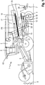
- Fig. 1 shows a schematic longitudinal sectional view of a combine harvester 1.
- the combine harvester 1 carries in its front region a height-adjustable cutting unit 2, which harvested grown crop 8 on a large width, merges in the lateral direction and passes to a inclined conveyor member 9.
- the crop 8 passes to threshing organs 3, which are usually designed as Mehrtrommeldrehiske.
- the threshing members 3 as shown in the Fig. 1 Through a openings of the concave 11 through a substantially consisting of a mixture of grains, short straw and chaff existing Erntegutstrom is deposited from the crop 8 through the openings of the concave 11 through which consists of a Preparation floor 12 drops.
- the oscillating driven preparation floor 12 By shaking movements of the oscillating driven preparation floor 12, the crop is promoted to the rear towards a cleaning device 4.
- the part of the crop stream which has not passed through the thresher basket 11 is conveyed further by the turning drum 16 to a separating device designed as an axial rotor 17 and extending in the longitudinal direction of the combine harvester 1.
- the axial rotor 17 is surrounded in its lower part by a semi-cylindrical sieve 19, through which a substantially consisting of a mixture of grains and ear fragments existing Erntegutstrom is deposited, which passes to a arranged below the sieve 19 return tray 21.
- Crop material essentially straw, which is ejected at the rear end 24 of the axial rotor 17, reaches a distribution device 7 at the rear of the combine harvester 1, where it is comminuted by a chopper 26 and finally discharged to the bottom of a field.
- the discharged through the sieve 19 crop is conveyed forward in the direction of threshing 3 and passed to the cleaning device 4, where the Erntegutstrom the return tray 21 associated with the through the concave 11 passed through crop flow of the preparation floor 12 is delivered to the cleaning device 4.
- the cleaning device 4 comprises a top wire 14, a bottom wire 15 and a cleaning fan 13, which generates a stream of air passing through and over the wires 14, 15.
- the cleaning fan 13 comprises a housing 28 and at least one fan wheel 30 arranged on at least one drive shaft (in FIG Fig. 1 not shown).
- the grain contained in the crop streams coming from the preparation soil 12 or from the return soil 21 successively passes through the upper sieve 14 and the lower sieve 15 and reaches, via an underlying ground 18, a screw conveyor 22 and a grain elevator 23 which transports it into a grain tank arranged in the back of the driver's cabin 6 5 promotes.
- Portions of the crop stream that are lighter than the grain are captured and entrained by the airflow of the cleaning blower 13 as they fall from the preparatory tray 12 to the top wire 14, from the top wire 14 to the bottom wire 15, or from the bottom wire 15 to the bottom 18, reach the distributor 7 and are excreted on this.
- a worm 20 rotating in the trench laterally clears the material to a tailings elevator 25, which carries it back to the threshing members 3.
- a control device 43 serves to control the working elements of the combine harvester 1.
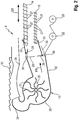
- FIG. 2 is a schematic view of the cleaning device 4 of the combine harvester 1 shown.
- the illustration shows a designed as a radial fan cleaning fan 13, in the housing 28, one or more fan wheels 30 are arranged.
- the fan wheels 30 are provided with blades 31 in the circumferential direction.
- a circular cross-section having housing 28, a channel section 32 and in the circumferential direction offset to this close, a Lauftaustritt 34 at.
- the air flow emerging from the channel section 32 in the direction of the arrow FR is supplied to the sieve arrangement consisting of the upper sieve 14 and the lower sieve 15.
- the channel section 32 widens along its longitudinal axis, so that the air flow both the top wire 14 and the bottom wire 15 passes both over and flows through from below.
- the upper sieve 14 and the lower sieve 15 are designed in a known manner as so-called lamellar sieves.
- the upper sieve 14 and the lower sieve 15 have a multiplicity of lamellae 27 whose inclination relative to the sieve plane can be adjusted, so that different sieve opening widths can be represented, depending on the crop type to be processed.
- This setting can be controlled by means of the control device 43.
- Arrow SR describes a direction of movement of the oscillating driven screen assembly, the upper sieve 14 and lower sieve 15 perform a forward and a reverse stroke movement.
- a partial air flow emerging from the air outlet 34 is directed by means of a guide plate 35 arranged below the preparation floor 12 to an area behind the preparation floor 12, in which the crop to be cleaned is delivered to the top wire 14 from the preparation floor 12.
- hinged flaps 29 are arranged.
- the flaps 29 extend depending on their pivotal position, starting from the upper edge or lower edge of the channel section 32 towards each other or in the direction of the screen assembly.
- the alternately controllable pivot positions are dashed lines in the representation of Fig. 2 illustrated.
- the actuation of the flaps 29 takes place in the illustrated embodiment by means of a mechanical Coupling between the sieve assembly and the respective flap 29.
- a coupling rod 33 connects the upper sieve 14 with the adjacently arranged to this flap 29, while another coupling rod 33 connects the lower sieve 15 with the adjacently arranged to this flap 29.
- the control of the flaps is thus effected indirectly by the control of upper wire 14 and lower wire 15 by the control device 43.
- the flaps 29 may also be driven by a single motor, for example by a respective flap 29 associated electric motor.
- the motor can be variably controlled as a function of the oscillation frequency and the direction of movement of the sieve arrangement.
- FIG. 3 shows a schematic partial view of the cleaning device 4 according to a second embodiment. Shown is only a part of the channel section 32, which directs the air flow emerging from this in the direction of the upper wire 14 and the lower wire 15.
- a respective lower paddle 36a and upper paddle 36b are arranged around a rotation axis 37.
- An arrow DR describes the direction of rotation of the two paddles 36a and 36b.
- the two paddles 36a and 36b each extend essentially over the entire width of the channel section 32.
- the upper paddle 36b is assigned to the upper sieve 14 and the lower paddle 36a to the lower sieve 15 in order to influence the supply of the air flow.
- the rotation of the respective paddle 36a, 36b has a phase offset of about 90 °.
- the lower, the lower wire 15 associated paddle 36a is perpendicular to the flow direction in the air flow, whereby the flow through the lower wire 15 is temporarily interrupted from the bottom.
- the upper, the top wire 14 associated paddle 36a is located in a direction substantially parallel to the flow direction, so that the emerging from the channel portion 32 air flow can flow through the top wire 14 from below almost unhindered.
- the rotation of the two paddles 36a and 36b about their axis of rotation 37 takes place in dependence on the direction of movement SR of the sieve arrangement. As in Fig.
- the respective rotational axis 37 of the respective paddle 36a and 36b can be driven by a single motor, in particular by an electric motor 38 or for example a hydraulic motor.
- the control of the electric motor 38 takes place in dependence on the activation of the drive or drives by the control device 43 which drive the screen assembly oscillating to perform a forward and a backward lifting movement of the upper wire 14 and the lower wire 15.
- the single-motor drive of the rotation axes 37 allows a rotation of the two paddles 36a, 36b with a variable phase offset, wherein this can also be zero.
- the frequency of the rotation can be varied.
- two or more revolutions of one or both paddles 36a, 36b can be set during a return stroke of the sieve arrangement.
- the single-motor drive is controlled in such a way that only a limited pivoting movement of the paddles 36a, 36 around the rotation axis 37 is performed.
- Fig. 4 is a schematic partial view of the cleaning device 4 according to a third embodiment shown.
- This third embodiment differs from those described above in that at the output of the channel portion 32, a two rollers 39 endlessly circulating belt 40 is arranged.
- the rollers 39 have a width which substantially corresponds to the width of the outlet opening of the channel section 32. At least one of the two rollers 39 is driven.
- the band 40 is divided into substantially parallelepiped openings 42 and closed band sections 41.
- the arrangement of the openings 42 between the band sections 41 is intermittent, that is, at least two openings 42 are provided.
- the number and extent of the band section 41 or the openings 41 in the direction of rotation DR of the band 40 can vary with the oscillation frequency of the screen arrangement.
- a corresponding arrangement of band sections 41 and openings 42 may be provided.
- the number of openings is chosen such that there are two band portions 41 in a mutually parallel opposite position when the supply of air flow to the top wire 14 or the bottom wire 15 is temporarily interrupted.
- differently configured bands 40 can be used with regard to the number and extent of the openings 42, which can be exchangeably applied to the rollers 39.
- the at least one driven roller 39 is preferably driven by a single motor.
- the control device 43 is used in the illustrated embodiment, the control of at least one of the rollers 39 driving motor in such a way that the belt 40 rotates in the oscillation cycle. In this case, according to the direction of movement of the screen assembly, the air flow supplied by the cleaning fan 13 is temporarily interrupted by the belt sections 41 or can pass unhindered through the openings 42.
- control device 43 By means of the control device 43 can be flexibly adjusted for all described embodiments, the ratio between the return stroke of the screen assembly and the interruption of the air flow.
- the ratio between the return movement of the screen assembly and the interruption of the air flow that is, the timing of the interruption of the air flow, 1: 1, 1: 2 or greater.
- the adjustable by the controller timing is based on the crop characteristics and the harvesting and operating conditions of the combine.
Landscapes
- Life Sciences & Earth Sciences (AREA)
- Environmental Sciences (AREA)
- Threshing Machine Elements (AREA)
Abstract
Die vorliegende Erfindung betrifft ein Verfahren zum Betreiben eines Reinigungseinrichtung (4) für einen Mähdrescher (1), umfassend zumindest eine Druckluftquelle (13), durch welche wenigstens ein Luftstrom bereitgestellt wird, sowie eine oszillierend angetriebene Siebanordnung, welche zumindest zwei in verschiedenen Ebenen angeordnete Siebe (14, 15) aufweist, die eine vorwärts und eine rückwärts gerichtete Hubbewegung (SR) ausführen und die von ihrer Unterseite her von dem wenigstens einen Luftstrom durchströmt werden, wobei wenigstens ein die Siebanordnung durchströmender Luftstrom während der rückwärts gerichteten Hubbewegung (SR) der Siebanordnung unterbrochen wird.The present invention relates to a method for operating a cleaning device (4) for a combine harvester (1), comprising at least one compressed air source (13) through which at least one air stream is provided, and an oscillating driven screen assembly comprising at least two screens arranged in different planes (14, 15), which perform a forward and a backward lifting movement (SR) and which are flowed through from the bottom by the at least one air flow, wherein at least one air flow passing through the screen assembly during the reverse stroke movement (SR) of the screen assembly is interrupted.
Description
Die vorliegende Erfindung betrifft ein Verfahren zum Betreiben einer Reinigungseinrichtung für einen Mähdrescher gemäß dem Oberbegriff des Anspruches 1 sowie eine Reinigungseinrichtung für einen Mähdrescher gemäß dem Oberbegriff des Anspruches 7.The present invention relates to a method for operating a cleaning device for a combine harvester according to the preamble of claim 1 and to a cleaning device for a combine harvester according to the preamble of
Aus der
Aufgabe der vorliegenden Erfindung ist es, ein Verfahren zum Betreiben einer Reinigungseinrichtung für einen Mähdrescher sowie eine Reinigungseinrichtung für einen Mähdrescher bereitzustellen, mit welchen sich unter Beibehaltung des für das Reinigungseinrichtung vorgesehenen Bauraumes eine höhere Leistungsdichte erreichen lässt.The object of the present invention is to provide a method for operating a cleaning device for a combine harvester as well as a cleaning device for a combine harvester with which, while maintaining the for the cleaning device provided space can achieve a higher power density.
Diese Aufgabe wird erfindungsgemäß durch ein Verfahren gemäß dem Anspruch 1 sowie durch eine Reinigungseinrichtung gemäß dem nebengeordneten Anspruch 7 erreicht.This object is achieved by a method according to claim 1 and by a cleaning device according to the
Gemäß dem Anspruch 1 wird ein Verfahren zum Betreiben einer Reinigungseinrichtung für einen Mähdrescher vorgeschlagen, wobei die Reinigungseinrichtung zumindest eine Druckluftquelle, durch welche wenigstens ein Luftstrom bereitgestellt wird, sowie eine oszillierend angetriebene Siebanordnung, welche zumindest zwei in verschiedenen Ebenen angeordnete Siebe aufweist, die eine vorwärts und eine rückwärts gerichtete Hubbewegung ausführen und die von ihrer Unterseite her von dem wenigstens einen Luftstrom durchströmt werden, umfasst, wobei das Verfahren dadurch gekennzeichnet ist, dass wenigstens ein die Siebanordnung durchströmender Luftstrom während der rückwärts gerichteten Hubbewegung der Siebanordnung unterbrochen wird. Durch das Verfahren wird erreicht, dass eine Abscheidung der Körner nicht nur während des Vorwärtshubes der Siebanordnung, das heißt während der Annäherung an die Körner stattfindet, sondern zusätzlich auch während des Rückwärtshubes der Siebanordnung, das heißt während sich die Siebanordnung von den Körnern entfernt. Hierbei kommt der Umstand zum Tragen, dass während des Rückhubes, während dessen sich der Abstand zwischen der Siebanordnung und den Körnern vergrößert, der wenigstens eine Luftstrom unterbrochen wird, so dass Körner trotz des größeren Abstands allein aufgrund ihrer Gewichtskraft durch die Öffnungen der zumindest ein Obersieb und ein Untersieb umfassenden Siebanordnung hindurchtreten können. Durch die temporäre Unterbrechung des wenigstens einen Luftstromes müssen die Körner lediglich den größeren Abstand während des Rückhubes überwinden, nicht aber zusätzlich die ihrer Bewegung entgegen gerichteten Kräfte, die aus dem wenigstens einen Luftstrom resultieren, der gemäß dem Stand der Technik auch während des Rückhubes der Siebanordnung bereitgestellt wird. Durch diese Maßnahme lässt sich unter Beibehaltung des Bauraums für die Reinigungseinrichtung eine höhere Leistungsdichte erreichen. Darüber hinaus wirkt sich das Verfahren positiv auf die Kornsauberkeit aus.According to claim 1, a method for operating a cleaning device for a combine harvester is proposed, wherein the cleaning device at least one compressed air source through which at least one air stream is provided, and an oscillating driven screen assembly, which has at least two arranged in different planes sieves, the one forward and perform a backward stroke movement and which are flowed through from the bottom by the at least one air flow, the method being characterized in that at least one of the air flow passing through the screen assembly is interrupted during the reverse stroke movement of the screen assembly. By the method is achieved that a deposition of the grains takes place not only during the forward stroke of the screen assembly, that is, during the approach to the grains, but additionally during the backward stroke of the screen assembly, that is, while the screen assembly of the grains removed. Here comes the fact that during the return stroke, during which increases the distance between the sieve assembly and the grains, the at least one air flow is interrupted so that grains despite the greater distance alone due to their weight through the openings of the at least one top wire and passing through a sieve assembly comprising a sieve. Due to the temporary interruption of the at least one air flow, the grains need only overcome the greater distance during the return stroke, but not in addition the opposing forces of their movement, resulting from the at least one air flow, according to the prior art during the return stroke of the sieve provided. This measure can be under Maintaining the installation space for the cleaning device to achieve a higher power density. In addition, the process has a positive effect on the grain cleanliness.
Hierzu sollte die Zuführung des wenigstens einen Luftstromes für die Gesamtdauer der rückwärts gerichteten Hubbewegung der Siebanordnung unterbrochen werden. Hierdurch kann erreicht werden, dass die Körner, trotz zunehmender Beabstandung der Sieboberflächen von dem Gutstrom, allein aufgrund ihrer Gewichtskraft durch die Siebe während der gesamten Rückhubphase abgeschieden werden.For this purpose, the supply of the at least one air flow should be interrupted for the entire duration of the rearward lifting movement of the screen assembly. In this way it can be achieved that the grains, despite increasing spacing of the wire surfaces of the product flow, are separated by the sieves during the entire return stroke phase solely due to their weight.
Vorzugsweise kann die Zuführung des wenigstens einen die Siebanordnung durchströmenden Luftstromes derart beschränkt werden, dass eine pulsierende Durchströmung wenigstens eines Siebes erreicht wird. Auf diese Weise ließe sich die Unterbrechung des Luftstromes auf die Rückhubbewegung beispielsweise nur des Obersiebes der Siebanordnung beschränken. Das Untersieb könnte hingegen während der Rückhubbewegung der Siebanordnung weiterhin mit einem kontinuierlichen Luftstrom beaufschlagt werden. Die Strömungsgeschwindigkeit dieses Luftstroms könnte dabei für die Dauer der Rückhubbewegung reduziert werden. Eine umgekehrte Konstellation ist ebenfalls denkbar.Preferably, the supply of the at least one air flow flowing through the sieve arrangement can be limited such that a pulsating flow through at least one sieve is achieved. In this way, the interruption of the air flow could be limited to the return stroke, for example, only the upper wire of the screen assembly. On the other hand, the lower sieve could continue to be subjected to a continuous air flow during the return stroke movement of the sieve arrangement. The flow rate of this air flow could be reduced for the duration of the return stroke. A reverse constellation is also conceivable.
Alternativ kann die Zuführung des wenigstens einen die Siebanordnung durchströmenden Luftstromes derart beschränkt werden, dass eine wechselweise Durchströmung des jeweils wenigstens einen in einer Ebene angeordneten Siebes erreicht wird.Alternatively, the supply of the at least one air stream flowing through the sieve arrangement can be restricted such that an alternating flow through each of the at least one sieve arranged in a plane is achieved.
Bevorzugt sollte die Unterbrechung der Luftströmung proportional zu der Hubbewegung der Siebanordnung angesteuert werden. Insbesondere beträgt das Verhältnis zwischen der Rückhubbewegung der Siebanordnung und der Unterbrechung des Luftstromes, das heißt die Taktung der Unterbrechung der Luftströmung, 1:1, 1:2 oder größer.Preferably, the interruption of the air flow should be controlled in proportion to the lifting movement of the screen assembly. In particular, the ratio between the return movement of the screen assembly and the interruption of the air flow, that is, the timing of the interruption of the air flow, 1: 1, 1: 2 or greater.
Vorzugsweise kann die Strömungsgeschwindigkeit der wenigstens einen Luftströmung während der vorwärts gerichteten Hubbewegung der Siebanordnung gegenüber der rückwärts gerichteten Hubbewegung erhöht werden. Der Reinigungseffekt kann dadurch verbessert werden, dass während des Vorwärtshubes der Siebanordnung eine gegenüber der rückwärts gerichteten Hubbewegung in Abhängigkeit vom Erntegut eingestellte Strömungsgeschwindigkeit des Luftstromes signifikant erhöhte Strömungsgeschwindigkeit eingestellt wird. Diese Maßnahme kann zu einer Verbesserung der Kornsauberkeit beitragen.Preferably, the flow rate of the at least one airflow may be increased during the forward swept motion of the screen assembly relative to the reverse sweep. The cleaning effect can be improved by setting a significantly increased flow velocity during the forward stroke of the sieve arrangement, a flow velocity of the air flow adjusted relative to the crop in the rearward direction. This measure can contribute to an improvement in grain cleanliness.
Des Weiteren wird die eingangs gestellte Aufgabe durch eine Reinigungseinrichtung gemäß dem nebengeordneten Anspruch 7 gelöst. Gemäß dem Anspruch 7 wird eine Reinigungseinrichtung für einen Mähdrescher vorgeschlagen, welche zumindest eine Druckluftquelle, zur Bereitstellung wenigstens eines Luftstromes, sowie eine oszillierend angetriebene Siebanordnung, welche zumindest zwei in verschiedenen Ebenen angeordnete Siebe aufweist, die eine vorwärts und eine rückwärts gerichtete Hubbewegung ausführen und die von ihrer Unterseite her von dem wenigstens einen Luftstrom durchströmt werden. Die Reinigungseinrichtung ist dadurch gekennzeichnet, dass zu der Ansteuerung der Reinigungseinrichtung eine Steuerungseinrichtung vorgesehen ist, welche dazu eingerichtet ist, Mittel anzusteuern, um den wenigstens einen die Siebanordnung durchströmenden Luftstrom während der rückwärts gerichteten Hubbewegung der Siebanordnung zu unterbrechen. Durch die Steuerungseinrichtung wird die Zufuhr des wenigstens einen Luftstromes unterbrochen, wenn die jeweilige Siebebene von der über die jeweilige Siebebene geförderten Gutschicht wegbewegt wird. Dies hat den Effekt, dass das schwerkraftbedingte Abscheiden gegen einen reduzierten Druck der die Siebanordnung durchströmenden Luftströmung erfolgt, sodass die freibeweglichen Körner in dem Gutgemisch einfacher/schneller die Siebebene zwecks Abscheidung erreichen.Furthermore, the object stated at the outset is achieved by a cleaning device according to the
Vorzugsweise kann die Steuerungseinrichtung dazu eingerichtet sein, Mittel in Abhängigkeit von der Hubbewegung der Siebanordnung ansteuern, die zur intermittierenden Unterbrechung des wenigstens einen Luftstromes eingerichtet sind. Hierzu können die Mittel mechanisch an die Siebanordnung gekoppelt sein. Auf diese Weise kann die Steuerungseinrichtung, die die Schwingungsfrequenz der Siebanordnung ansteuert, gleichzeitig die Mittel zur intermittierenden Unterbrechung des wenigstens einen Luftstromes ansteuern. Alternativ kann die Steuerungseinrichtung einen oder mehrere einzelmotorische Antriebe ansteuern, welche dem Antrieb der Mittel zur intermittierenden Unterbrechung des wenigstens einen Luftstromes dienen.Preferably, the control device may be configured to control means in response to the lifting movement of the sieve assembly, which set up for the intermittent interruption of the at least one air flow are. For this purpose, the means may be mechanically coupled to the screen assembly. In this way, the control device, which controls the oscillation frequency of the sieve arrangement, simultaneously control the means for the intermittent interruption of the at least one air flow. Alternatively, the control device can control one or more individual motor drives, which serve to drive the means for the intermittent interruption of the at least one air flow.
So können die Mittel als wenigstens ein Gebläse mit einem auf die Siebanordnung gerichteten Strömungskanal ausgeführt sein. Bei dem wenigstens einen Gebläse kann es sich um ein Axial- oder ein Radialgebläse handeln. Die Steuerungseinrichtung kann dazu eingerichtet sein, den oder die Antriebe des wenigstens einen Gebläses derart anzusteuern, dass sich ein Geschwindigkeitsprofil der Luftströmung einstellt, welches mit der Hubbewegung der Siebanordnung korreliert.Thus, the means may be designed as at least one fan with a directed to the sieve flow channel. The at least one fan may be an axial or a radial fan. The control device may be configured to control the drive or drives of the at least one fan in such a way that a velocity profile of the air flow is established, which correlates with the lifting movement of the screen arrangement.
Bevorzugt kann das wenigstens eine Gebläse als ein Radialgebläse ausgeführt sein, dessen Schaufelanzahl an die Schwingungsfrequenz der Siebanordnung angepasst ist.Preferably, the at least one fan can be designed as a radial fan whose number of blades is adapted to the oscillation frequency of the sieve arrangement.
Gemäß einer bevorzugten Weiterbildung können die Mittel als eine in einen Siebrahmen der Siebanordnung integrierte Düsenanordnung ausgeführt sein.According to a preferred development, the means can be embodied as a nozzle arrangement integrated into a sieve frame of the sieve arrangement.
Weiterhin können die Mittel als zwei um Achsen begrenzt schwenkbare Klappen am Ausgang eines auf die Siebanordnung gerichteten Strömungskanal ausgeführt sein. Hierbei können die Klappen mechanisch mit der Siebanordnung gekoppelt sein. Die mechanische Kopplung kann beispielsweise durch Koppelstangen realisiert werden. Die Koppelstangen können in Abhängigkeit von der Bewegung der Siebanordnung die Klappen derart betätigen, dass die Luftströmung während des Vorwärtshubes der Siebanordnung ungehindert die zumindest zwei Siebe der Siebabordnung durchströmt, während für die Dauer der Rückhubbewegung der Siebanordnung die Klappen den Strömungskanal verschließen. Alternativ können die Klappen derart durch die Koppelstangen betätigt werden, dass in Abhängigkeit von der Bewegung der Siebanordnung die Luftströmung wechselweise nur der einen oder nur der anderen Siebebene zugeführt wird.Furthermore, the means may be designed as two hinged flaps limited by axes at the output of a directed onto the sieve flow channel. In this case, the flaps can be mechanically coupled to the sieve arrangement. The mechanical coupling can be realized for example by coupling rods. Depending on the movement of the sieve arrangement, the coupling rods can actuate the flaps in such a way that the air flow flows through the at least two sieves of the sieve section unhindered during the forward stroke of the sieve arrangement, while the flaps close the flow channel for the duration of the return stroke movement of the sieve arrangement. Alternatively, the flaps may be actuated by the coupling rods such that, depending on the movement of the screen assembly, the air flow is alternately supplied to only one or only the other screen plane.
In einer bevorzugten Weiterbildung können die Klappen einzelmotorisch betätigbar sein, so dass ein einseitiges oder wechselweises Freigeben und Sperren des Ausgangs des Strömungskanals ansteuerbar ist. Dazu könnten die einzelmotorischen Antriebe der Klappen in der Weise von der Steuerungseinrichtung angesteuert werden, dass der Luftstrom während des Rückwärtshubes der Siebanordnung nur eine der beiden Siebebenen durchströmt. Denkbar ist eine wechselweise Unterbrechung des den Siebebenen zugeführten Luftstromes, so dass während eines ersten Rückhubes der Siebanordnung nur das Obersieb und während eines zweiten Rückhubes nur das Untersieb durchströmt wird.In a preferred embodiment, the flaps can be actuated by a single motor, so that a one-sided or alternating release and blocking of the output of the flow channel can be controlled. For this purpose, the individual motor drives of the flaps could be controlled by the control device in such a way that the air flow only flows through one of the two screen planes during the reverse stroke of the screen arrangement. It is conceivable to alternately interrupt the air flow supplied to the screen planes, so that only the upper screen is passed through during a first return stroke of the screen assembly, and only the lower screen is passed through during a second return stroke.
Eine vorteilhafte Weiterbildung gemäß dem Anspruch 13 sieht vor, dass die Mittel als zwei um Achsen rotierende Paddel am Ausgang eines auf die Siebanordnung gerichteten Strömungskanal ausgeführt sein können. Mittels der rotierenden Paddel lässt sich der aus dem Strömungskanal austretende Luftstrom unterbrechen, wobei die Dauer der Unterbrechung, das heißt die Drehzahl der Paddel, in Abhängigkeit von der Dauer der Rückhubbewegung der Siebanordnung gesteuert wird. Auch bei dieser Weiterbildung können die Paddel einzelmotorisch angetrieben und in Abhängigkeit von der Bewegungsrichtung der Siebanordnung angesteuert werden. Dabei können die einzelmotorischen Antriebe synchron angesteuert werden, so dass die Zuführung des wenigstens einen Luftstromes zu beiden Siebebenen unterbrochen wird. Ebenfalls denkbar ist es, einen Phasenversatz der Rotationsbewegung einzustellen, um wechselweise nur das Obersieb oder nur das Untersieb während des Rückhubes der Siebanordnung von dem wenigstens einen Luftstrom durchströmen zu lassen.An advantageous development according to
Eine weitere bevorzugte Weiterbildung sieht vor, dass die Mittel als zumindest ein um zwei Rollen umlaufendes Band mit darin intermittierend angeordneten Öffnungen ausgeführt sein kann, das am Ausgang eines auf die Siebanordnung gerichteten Strömungskanal angeordnet ist.A further preferred embodiment provides that the means as at least one circulating around two rollers belt with intermittently arranged therein Openings may be made, which is arranged at the output of a directed to the sieve assembly flow channel.
Des Weiteren kann im Strömungskanal des wenigstens einen Gebläses zumindest eine Membrane angeordnet sein, die der temporären Verengung oder dem temporären Verschließen des Strömungskanals dient. In einer Ausgestaltung mit nur einer Membrane kann diese in einer der vertikal verlaufenden Seitenwände des Strömungskanals des mindestens einen Gebläses angeordnet sein. Weiterhin können beispielsweise zwei Membranen einander gegenüberliegend in den vertikalen oder horizontalen Seitenwänden angeordnet sein. Des Weiteren können auch mehr als zwei Membranen in dem Strömungskanal angeordnet sein, um die Wege zu reduzieren, welche die Membranen zurücklegen müssen, um den Strömungskanal temporär zu verengen oder zu verschließen. Zur Betätigung der Membranen können diese mittels einer Koppelvorrichtung an die Siebbewegung gekoppelt sein, so dass die Membranen passiv angesteuert werden. Alternativ können die Membranen aktiv durch ein Aktorik betätigbar sein, die wiederum in Abhängigkeit von der Siebbewegung angesteuert wird.Furthermore, at least one diaphragm may be arranged in the flow channel of the at least one fan, which serves for the temporary narrowing or the temporary closing of the flow channel. In an embodiment with only one membrane, it can be arranged in one of the vertically extending side walls of the flow channel of the at least one blower. Furthermore, for example, two membranes may be arranged opposite each other in the vertical or horizontal side walls. Furthermore, more than two diaphragms may be disposed in the flow channel to reduce the distances the membranes must travel to temporarily constrict or close the flow channel. For actuation of the membranes they can be coupled by means of a coupling device to the wire movement, so that the membranes are driven passively. Alternatively, the membranes can be actively actuated by an actuator, which in turn is controlled as a function of the sieve movement.
Die vorliegende Erfindung wird nachstehend anhand von in den Zeichnungen dargestellten Ausführungsbeispielen näher erläutert.The present invention will be explained below with reference to exemplary embodiments illustrated in the drawings.
Es zeigen:
- Fig. 1
- eine schematisierte Längsschnittdarstellung eines Mähdreschers;
- Fig. 2
- eine schematische Ansicht einer Reinigungseinrichtung des Mähdreschers;
- Fig. 3
- eine schematische Teilansicht einer Reinigungseinrichtung gemäß einer zweiten Ausführungsform;
- Fig. 4
- eine schematische Teilansicht einer Reinigungseinrichtung gemäß einer dritten Ausführungsform.
- Fig. 1
- a schematic longitudinal sectional view of a combine harvester;
- Fig. 2
- a schematic view of a cleaning device of the combine harvester;
- Fig. 3
- a schematic partial view of a cleaning device according to a second embodiment;
- Fig. 4
- a schematic partial view of a cleaning device according to a third embodiment.
Die Darstellung in
Der nicht durch den Dreschkorb 11 hindurch getretene Teil des Erntegutstroms wird von der Wendetrommel 16 zu einer als Axialrotor 17 ausgeführten, sich in Längsrichtung des Mähdreschers 1 erstreckenden Abscheidevorrichtung weiterbefördert. Der Axialrotor 17 ist in seinem unteren Bereich von einem halbzylindrischen Sieb 19 umgeben, durch das ein im Wesentlichen aus einem Gemisch aus Körnern und Ährenbruchstücken bestehender Erntegutstrom abgeschieden wird, der auf einen unterhalb des Siebs 19 angeordneten Rücklaufboden 21 gelangt.The part of the crop stream which has not passed through the thresher basket 11 is conveyed further by the turning
Anstelle eines einzelnen Axialrotors 17 könnten auch zwei Axialrotoren parallel nebeneinander vorgesehen sein. Alternativ kann als Abscheidevorrichtung eine Hordenschüttlervorrichtung anstelle des Axialrotors 17 zum Einsatz kommen.Instead of a single
Erntegut, im Wesentlichen Stroh, welches am rückwärtigen Ende 24 des Axialrotors 17 ausgeworfen wird, gelangt zu einer Verteilvorrichtung 7 am Heck des Mähdreschers 1, wo es von einem Häcksler 26 zerkleinert und schließlich auf den Boden eines Feldes ausgebracht wird.Crop material, essentially straw, which is ejected at the
Auf dem rüttelnd bewegten Rücklaufboden 21 wird das durch das Sieb 19 abgegebene Erntegut vorwärts in Richtung der Dreschorgane 3 gefördert und an die Reinigungseinrichtung 4 übergeben, wo sich der Erntegutstrom des Rücklaufbodens 21 mit dem durch den Dreschkorb 11 hindurch getretenen Erntegutstrom vereinigt, der von dem Vorbereitungsboden 12 an die Reinigungseinrichtung 4 abgegeben wird. Die Reinigungseinrichtung 4 umfasst ein Obersieb 14, ein Untersieb 15 und ein Reinigungsgebläse 13, welches einen durch und über die Siebe 14, 15 streichenden Luftstrom erzeugt. Das Reinigungsgebläse 13 umfasst ein Gehäuse 28 sowie zumindest ein auf wenigstens einer Antriebswelle angeordnetes Lüfterrad 30 (in
Anteile des Erntegutstroms, die leichter als das Korn sind, werden beim Herabfallen vom Vorbereitungsboden 12 auf das Obersieb 14, vom Obersieb 14 auf das Untersieb 15 oder vom Untersieb 15 auf den Boden 18 von dem Luftstrom des Reinigungsgebläses 13 erfasst und mitgerissen, erreichen den Verteiler 7 und werden über diesen ausgeschieden. Schwere, gröbere Anteile des Erntegutstromes, wie unausgedroschene Ährenspitzen, gelangen mittels einer Überkehr am rückwärtigen Ende der Siebe 14, 15 in einen unterhalb der Siebe 14, 15 quer verlaufenden Graben. Eine in dem Graben rotierende Schnecke 20 räumt das Material seitwärts zu einem Überkehrelevator 25, der es zurück zu den Dreschorganen 3 befördert. Eine Steuerungseinrichtung 43 dient der Ansteuerung der Arbeitsorgane des Mähdreschers 1.Portions of the crop stream that are lighter than the grain are captured and entrained by the airflow of the
In
Am Ausgang des Kanalabschnittes 32 sind zwei um Schwenkachsen 36 begrenzt schwenkbare Klappen 29 angeordnet. Die Klappen 29 erstrecken sich, in Abhängigkeit von ihrer Schwenkposition, ausgehend von der Oberkante beziehungsweise Unterkante des Kanalabschnittes 32 aufeinander zu oder in Richtung der Siebanordnung. Die wechselweise ansteuerbaren Schwenkpositionen sind strichliniert in der Darstellung der
Die Darstellung in
In
Mittels der Steuerungseinrichtung 43 lässt sich für alle beschriebenen Ausführungsformen das Verhältnis zwischen der Rückhubbewegung der Siebanordnung und der Unterbrechung des Luftstromes flexibel einstellen. So beträgt das Verhältnis zwischen der Rückhubbewegung der Siebanordnung und der Unterbrechung des Luftstromes, das heißt die Taktung der Unterbrechung der Luftströmung, 1:1, 1:2 oder größer. Die mittels der Steuerungseinrichtung einstellbare Taktung orientiert sich an den Ernteguteigenschaften sowie den Ernte- und Betriebsbedingungen des Mähdreschers 1.
Claims (15)
Applications Claiming Priority (1)
| Application Number | Priority Date | Filing Date | Title |
|---|---|---|---|
| DE102016103234.4A DE102016103234A1 (en) | 2016-02-24 | 2016-02-24 | Method for operating a cleaning device for a combine harvester |
Publications (2)
| Publication Number | Publication Date |
|---|---|
| EP3210461A1 true EP3210461A1 (en) | 2017-08-30 |
| EP3210461B1 EP3210461B1 (en) | 2020-02-12 |
Family
ID=57517790
Family Applications (1)
| Application Number | Title | Priority Date | Filing Date |
|---|---|---|---|
| EP16202645.4A Active EP3210461B1 (en) | 2016-02-24 | 2016-12-07 | Method for operating a cleaning device of a combine harvester |
Country Status (2)
| Country | Link |
|---|---|
| EP (1) | EP3210461B1 (en) |
| DE (1) | DE102016103234A1 (en) |
Families Citing this family (1)
| Publication number | Priority date | Publication date | Assignee | Title |
|---|---|---|---|---|
| US20230039498A1 (en) * | 2021-08-06 | 2023-02-09 | Deere & Company | Cleaning fan airflow control system |
Citations (5)
| Publication number | Priority date | Publication date | Assignee | Title |
|---|---|---|---|---|
| EP0475453A2 (en) * | 1990-09-13 | 1992-03-18 | SAME S.p.A. | Grain cleaning apparatus for a combine harvester |
| EP0701772A1 (en) * | 1994-09-17 | 1996-03-20 | New Holland Belgium N.V. | Cleaning means for an agricultural harvesting machine |
| EP2476304A1 (en) * | 2011-01-14 | 2012-07-18 | CLAAS Selbstfahrende Erntemaschinen GmbH | Combine harvester |
| WO2012097933A1 (en) * | 2011-01-17 | 2012-07-26 | Agco A/S | Combine harvester grain cleaning apparatus |
| EP2708111A1 (en) | 2012-09-13 | 2014-03-19 | CNH Belgium N.V. | A combine harvester sieve assembly with an integrated air cleaning system |
-
2016
- 2016-02-24 DE DE102016103234.4A patent/DE102016103234A1/en not_active Withdrawn
- 2016-12-07 EP EP16202645.4A patent/EP3210461B1/en active Active
Patent Citations (5)
| Publication number | Priority date | Publication date | Assignee | Title |
|---|---|---|---|---|
| EP0475453A2 (en) * | 1990-09-13 | 1992-03-18 | SAME S.p.A. | Grain cleaning apparatus for a combine harvester |
| EP0701772A1 (en) * | 1994-09-17 | 1996-03-20 | New Holland Belgium N.V. | Cleaning means for an agricultural harvesting machine |
| EP2476304A1 (en) * | 2011-01-14 | 2012-07-18 | CLAAS Selbstfahrende Erntemaschinen GmbH | Combine harvester |
| WO2012097933A1 (en) * | 2011-01-17 | 2012-07-26 | Agco A/S | Combine harvester grain cleaning apparatus |
| EP2708111A1 (en) | 2012-09-13 | 2014-03-19 | CNH Belgium N.V. | A combine harvester sieve assembly with an integrated air cleaning system |
Also Published As
| Publication number | Publication date |
|---|---|
| DE102016103234A1 (en) | 2017-08-24 |
| EP3210461B1 (en) | 2020-02-12 |
Similar Documents
| Publication | Publication Date | Title |
|---|---|---|
| EP1163834B2 (en) | Spreading device for chopper | |
| DE60013249T2 (en) | ADAPTABILITY IN AXIAL FLOW COMBINERS | |
| EP2298061B1 (en) | Method for distributing a flow of goods on a field and shredding and distributing device | |
| EP2591664B1 (en) | Sieve for a cleaning device of a combine harvester | |
| EP1790208B1 (en) | Combine with suction fan | |
| EP1733611B1 (en) | Sieve for the grain cleaning apparatus of a combine harvester | |
| DE3042731C2 (en) | ||
| DE3042734A1 (en) | HARVESTER | |
| DE2430718B2 (en) | Harvester | |
| EP2036422B1 (en) | Combine harvester with straw shredder | |
| DE3042737A1 (en) | HARVESTER | |
| DE3042735A1 (en) | HARVESTER | |
| EP3453248A1 (en) | Combine harvester | |
| DE3042736C2 (en) | ||
| DE3042733A1 (en) | HARVESTER | |
| DE2830163B2 (en) | Cleaning device for combine harvesters | |
| EP3210461B1 (en) | Method for operating a cleaning device of a combine harvester | |
| EP2805602B1 (en) | Combine harvester | |
| EP3207788B1 (en) | Cleaning device | |
| EP2036423B1 (en) | Combine harvester with spreader for chopped crop | |
| EP1820390B1 (en) | Combine-harvester with multi-stage separating zone | |
| EP1820389B1 (en) | Combine-harvester with multi-stage separating zone | |
| EP2181578A2 (en) | Combine harvester and harvesting method | |
| DE69512257T2 (en) | DRIVING DEVICE FOR COMBINATION | |
| EP3797574B1 (en) | Distributing device for chopped material |
Legal Events
| Date | Code | Title | Description |
|---|---|---|---|
| PUAI | Public reference made under article 153(3) epc to a published international application that has entered the european phase |
Free format text: ORIGINAL CODE: 0009012 |
|
| STAA | Information on the status of an ep patent application or granted ep patent |
Free format text: STATUS: THE APPLICATION HAS BEEN PUBLISHED |
|
| AK | Designated contracting states |
Kind code of ref document: A1 Designated state(s): AL AT BE BG CH CY CZ DE DK EE ES FI FR GB GR HR HU IE IS IT LI LT LU LV MC MK MT NL NO PL PT RO RS SE SI SK SM TR |
|
| AX | Request for extension of the european patent |
Extension state: BA ME |
|
| STAA | Information on the status of an ep patent application or granted ep patent |
Free format text: STATUS: REQUEST FOR EXAMINATION WAS MADE |
|
| 17P | Request for examination filed |
Effective date: 20180228 |
|
| RBV | Designated contracting states (corrected) |
Designated state(s): AL AT BE BG CH CY CZ DE DK EE ES FI FR GB GR HR HU IE IS IT LI LT LU LV MC MK MT NL NO PL PT RO RS SE SI SK SM TR |
|
| GRAP | Despatch of communication of intention to grant a patent |
Free format text: ORIGINAL CODE: EPIDOSNIGR1 |
|
| STAA | Information on the status of an ep patent application or granted ep patent |
Free format text: STATUS: GRANT OF PATENT IS INTENDED |
|
| INTG | Intention to grant announced |
Effective date: 20190906 |
|
| GRAS | Grant fee paid |
Free format text: ORIGINAL CODE: EPIDOSNIGR3 |
|
| GRAA | (expected) grant |
Free format text: ORIGINAL CODE: 0009210 |
|
| STAA | Information on the status of an ep patent application or granted ep patent |
Free format text: STATUS: THE PATENT HAS BEEN GRANTED |
|
| AK | Designated contracting states |
Kind code of ref document: B1 Designated state(s): AL AT BE BG CH CY CZ DE DK EE ES FI FR GB GR HR HU IE IS IT LI LT LU LV MC MK MT NL NO PL PT RO RS SE SI SK SM TR |
|
| REG | Reference to a national code |
Ref country code: GB Ref legal event code: FG4D Free format text: NOT ENGLISH |
|
| REG | Reference to a national code |
Ref country code: CH Ref legal event code: EP |
|
| REG | Reference to a national code |
Ref country code: AT Ref legal event code: REF Ref document number: 1230869 Country of ref document: AT Kind code of ref document: T Effective date: 20200215 |
|
| REG | Reference to a national code |
Ref country code: DE Ref legal event code: R096 Ref document number: 502016008691 Country of ref document: DE |
|
| REG | Reference to a national code |
Ref country code: IE Ref legal event code: FG4D Free format text: LANGUAGE OF EP DOCUMENT: GERMAN |
|
| PG25 | Lapsed in a contracting state [announced via postgrant information from national office to epo] |
Ref country code: FI Free format text: LAPSE BECAUSE OF FAILURE TO SUBMIT A TRANSLATION OF THE DESCRIPTION OR TO PAY THE FEE WITHIN THE PRESCRIBED TIME-LIMIT Effective date: 20200212 Ref country code: RS Free format text: LAPSE BECAUSE OF FAILURE TO SUBMIT A TRANSLATION OF THE DESCRIPTION OR TO PAY THE FEE WITHIN THE PRESCRIBED TIME-LIMIT Effective date: 20200212 Ref country code: NO Free format text: LAPSE BECAUSE OF FAILURE TO SUBMIT A TRANSLATION OF THE DESCRIPTION OR TO PAY THE FEE WITHIN THE PRESCRIBED TIME-LIMIT Effective date: 20200512 |
|
| REG | Reference to a national code |
Ref country code: LT Ref legal event code: MG4D |
|
| REG | Reference to a national code |
Ref country code: NL Ref legal event code: MP Effective date: 20200212 |
|
| PG25 | Lapsed in a contracting state [announced via postgrant information from national office to epo] |
Ref country code: BG Free format text: LAPSE BECAUSE OF FAILURE TO SUBMIT A TRANSLATION OF THE DESCRIPTION OR TO PAY THE FEE WITHIN THE PRESCRIBED TIME-LIMIT Effective date: 20200512 Ref country code: LV Free format text: LAPSE BECAUSE OF FAILURE TO SUBMIT A TRANSLATION OF THE DESCRIPTION OR TO PAY THE FEE WITHIN THE PRESCRIBED TIME-LIMIT Effective date: 20200212 Ref country code: SE Free format text: LAPSE BECAUSE OF FAILURE TO SUBMIT A TRANSLATION OF THE DESCRIPTION OR TO PAY THE FEE WITHIN THE PRESCRIBED TIME-LIMIT Effective date: 20200212 Ref country code: HR Free format text: LAPSE BECAUSE OF FAILURE TO SUBMIT A TRANSLATION OF THE DESCRIPTION OR TO PAY THE FEE WITHIN THE PRESCRIBED TIME-LIMIT Effective date: 20200212 Ref country code: IS Free format text: LAPSE BECAUSE OF FAILURE TO SUBMIT A TRANSLATION OF THE DESCRIPTION OR TO PAY THE FEE WITHIN THE PRESCRIBED TIME-LIMIT Effective date: 20200612 Ref country code: GR Free format text: LAPSE BECAUSE OF FAILURE TO SUBMIT A TRANSLATION OF THE DESCRIPTION OR TO PAY THE FEE WITHIN THE PRESCRIBED TIME-LIMIT Effective date: 20200513 |
|
| PG25 | Lapsed in a contracting state [announced via postgrant information from national office to epo] |
Ref country code: NL Free format text: LAPSE BECAUSE OF FAILURE TO SUBMIT A TRANSLATION OF THE DESCRIPTION OR TO PAY THE FEE WITHIN THE PRESCRIBED TIME-LIMIT Effective date: 20200212 |
|
| PG25 | Lapsed in a contracting state [announced via postgrant information from national office to epo] |
Ref country code: DK Free format text: LAPSE BECAUSE OF FAILURE TO SUBMIT A TRANSLATION OF THE DESCRIPTION OR TO PAY THE FEE WITHIN THE PRESCRIBED TIME-LIMIT Effective date: 20200212 Ref country code: SM Free format text: LAPSE BECAUSE OF FAILURE TO SUBMIT A TRANSLATION OF THE DESCRIPTION OR TO PAY THE FEE WITHIN THE PRESCRIBED TIME-LIMIT Effective date: 20200212 Ref country code: EE Free format text: LAPSE BECAUSE OF FAILURE TO SUBMIT A TRANSLATION OF THE DESCRIPTION OR TO PAY THE FEE WITHIN THE PRESCRIBED TIME-LIMIT Effective date: 20200212 Ref country code: SK Free format text: LAPSE BECAUSE OF FAILURE TO SUBMIT A TRANSLATION OF THE DESCRIPTION OR TO PAY THE FEE WITHIN THE PRESCRIBED TIME-LIMIT Effective date: 20200212 Ref country code: CZ Free format text: LAPSE BECAUSE OF FAILURE TO SUBMIT A TRANSLATION OF THE DESCRIPTION OR TO PAY THE FEE WITHIN THE PRESCRIBED TIME-LIMIT Effective date: 20200212 Ref country code: RO Free format text: LAPSE BECAUSE OF FAILURE TO SUBMIT A TRANSLATION OF THE DESCRIPTION OR TO PAY THE FEE WITHIN THE PRESCRIBED TIME-LIMIT Effective date: 20200212 Ref country code: PT Free format text: LAPSE BECAUSE OF FAILURE TO SUBMIT A TRANSLATION OF THE DESCRIPTION OR TO PAY THE FEE WITHIN THE PRESCRIBED TIME-LIMIT Effective date: 20200705 Ref country code: LT Free format text: LAPSE BECAUSE OF FAILURE TO SUBMIT A TRANSLATION OF THE DESCRIPTION OR TO PAY THE FEE WITHIN THE PRESCRIBED TIME-LIMIT Effective date: 20200212 Ref country code: ES Free format text: LAPSE BECAUSE OF FAILURE TO SUBMIT A TRANSLATION OF THE DESCRIPTION OR TO PAY THE FEE WITHIN THE PRESCRIBED TIME-LIMIT Effective date: 20200212 |
|
| REG | Reference to a national code |
Ref country code: DE Ref legal event code: R097 Ref document number: 502016008691 Country of ref document: DE |
|
| PLBE | No opposition filed within time limit |
Free format text: ORIGINAL CODE: 0009261 |
|
| STAA | Information on the status of an ep patent application or granted ep patent |
Free format text: STATUS: NO OPPOSITION FILED WITHIN TIME LIMIT |
|
| 26N | No opposition filed |
Effective date: 20201113 |
|
| PG25 | Lapsed in a contracting state [announced via postgrant information from national office to epo] |
Ref country code: IT Free format text: LAPSE BECAUSE OF FAILURE TO SUBMIT A TRANSLATION OF THE DESCRIPTION OR TO PAY THE FEE WITHIN THE PRESCRIBED TIME-LIMIT Effective date: 20200212 |
|
| PG25 | Lapsed in a contracting state [announced via postgrant information from national office to epo] |
Ref country code: PL Free format text: LAPSE BECAUSE OF FAILURE TO SUBMIT A TRANSLATION OF THE DESCRIPTION OR TO PAY THE FEE WITHIN THE PRESCRIBED TIME-LIMIT Effective date: 20200212 Ref country code: SI Free format text: LAPSE BECAUSE OF FAILURE TO SUBMIT A TRANSLATION OF THE DESCRIPTION OR TO PAY THE FEE WITHIN THE PRESCRIBED TIME-LIMIT Effective date: 20200212 |
|
| REG | Reference to a national code |
Ref country code: CH Ref legal event code: PL |
|
| GBPC | Gb: european patent ceased through non-payment of renewal fee |
Effective date: 20201207 |
|
| PG25 | Lapsed in a contracting state [announced via postgrant information from national office to epo] |
Ref country code: MC Free format text: LAPSE BECAUSE OF FAILURE TO SUBMIT A TRANSLATION OF THE DESCRIPTION OR TO PAY THE FEE WITHIN THE PRESCRIBED TIME-LIMIT Effective date: 20200212 |
|
| PG25 | Lapsed in a contracting state [announced via postgrant information from national office to epo] |
Ref country code: IE Free format text: LAPSE BECAUSE OF NON-PAYMENT OF DUE FEES Effective date: 20201207 Ref country code: LU Free format text: LAPSE BECAUSE OF NON-PAYMENT OF DUE FEES Effective date: 20201207 Ref country code: FR Free format text: LAPSE BECAUSE OF NON-PAYMENT OF DUE FEES Effective date: 20201231 |
|
| PG25 | Lapsed in a contracting state [announced via postgrant information from national office to epo] |
Ref country code: CH Free format text: LAPSE BECAUSE OF NON-PAYMENT OF DUE FEES Effective date: 20201231 Ref country code: LI Free format text: LAPSE BECAUSE OF NON-PAYMENT OF DUE FEES Effective date: 20201231 Ref country code: GB Free format text: LAPSE BECAUSE OF NON-PAYMENT OF DUE FEES Effective date: 20201207 |
|
| PG25 | Lapsed in a contracting state [announced via postgrant information from national office to epo] |
Ref country code: TR Free format text: LAPSE BECAUSE OF FAILURE TO SUBMIT A TRANSLATION OF THE DESCRIPTION OR TO PAY THE FEE WITHIN THE PRESCRIBED TIME-LIMIT Effective date: 20200212 Ref country code: MT Free format text: LAPSE BECAUSE OF FAILURE TO SUBMIT A TRANSLATION OF THE DESCRIPTION OR TO PAY THE FEE WITHIN THE PRESCRIBED TIME-LIMIT Effective date: 20200212 Ref country code: CY Free format text: LAPSE BECAUSE OF FAILURE TO SUBMIT A TRANSLATION OF THE DESCRIPTION OR TO PAY THE FEE WITHIN THE PRESCRIBED TIME-LIMIT Effective date: 20200212 |
|
| PG25 | Lapsed in a contracting state [announced via postgrant information from national office to epo] |
Ref country code: MK Free format text: LAPSE BECAUSE OF FAILURE TO SUBMIT A TRANSLATION OF THE DESCRIPTION OR TO PAY THE FEE WITHIN THE PRESCRIBED TIME-LIMIT Effective date: 20200212 Ref country code: AL Free format text: LAPSE BECAUSE OF FAILURE TO SUBMIT A TRANSLATION OF THE DESCRIPTION OR TO PAY THE FEE WITHIN THE PRESCRIBED TIME-LIMIT Effective date: 20200212 |
|
| REG | Reference to a national code |
Ref country code: AT Ref legal event code: MM01 Ref document number: 1230869 Country of ref document: AT Kind code of ref document: T Effective date: 20211207 |
|
| PG25 | Lapsed in a contracting state [announced via postgrant information from national office to epo] |
Ref country code: AT Free format text: LAPSE BECAUSE OF NON-PAYMENT OF DUE FEES Effective date: 20211207 |
|
| P01 | Opt-out of the competence of the unified patent court (upc) registered |
Effective date: 20230516 |
|
| PGFP | Annual fee paid to national office [announced via postgrant information from national office to epo] |
Ref country code: DE Payment date: 20231214 Year of fee payment: 8 |
|
| PGFP | Annual fee paid to national office [announced via postgrant information from national office to epo] |
Ref country code: BE Payment date: 20231220 Year of fee payment: 8 |