EP3210209B1 - Apparatuses and methods for segmented sgs lines - Google Patents
Apparatuses and methods for segmented sgs lines Download PDFInfo
- Publication number
- EP3210209B1 EP3210209B1 EP15852706.9A EP15852706A EP3210209B1 EP 3210209 B1 EP3210209 B1 EP 3210209B1 EP 15852706 A EP15852706 A EP 15852706A EP 3210209 B1 EP3210209 B1 EP 3210209B1
- Authority
- EP
- European Patent Office
- Prior art keywords
- memory
- subblocks
- select gate
- subblock
- line
- Prior art date
- Legal status (The legal status is an assumption and is not a legal conclusion. Google has not performed a legal analysis and makes no representation as to the accuracy of the status listed.)
- Active
Links
- 238000000034 method Methods 0.000 title claims description 4
- 230000015654 memory Effects 0.000 claims description 259
- 230000008878 coupling Effects 0.000 claims description 5
- 238000010168 coupling process Methods 0.000 claims description 5
- 238000005859 coupling reaction Methods 0.000 claims description 5
- 238000010586 diagram Methods 0.000 description 17
- 230000004044 response Effects 0.000 description 1
- 230000007704 transition Effects 0.000 description 1
Images

Classifications
-
- G—PHYSICS
- G11—INFORMATION STORAGE
- G11C—STATIC STORES
- G11C16/00—Erasable programmable read-only memories
- G11C16/02—Erasable programmable read-only memories electrically programmable
- G11C16/04—Erasable programmable read-only memories electrically programmable using variable threshold transistors, e.g. FAMOS
- G11C16/0483—Erasable programmable read-only memories electrically programmable using variable threshold transistors, e.g. FAMOS comprising cells having several storage transistors connected in series
-
- G—PHYSICS
- G11—INFORMATION STORAGE
- G11C—STATIC STORES
- G11C16/00—Erasable programmable read-only memories
- G11C16/02—Erasable programmable read-only memories electrically programmable
- G11C16/06—Auxiliary circuits, e.g. for writing into memory
- G11C16/08—Address circuits; Decoders; Word-line control circuits
-
- G—PHYSICS
- G11—INFORMATION STORAGE
- G11C—STATIC STORES
- G11C16/00—Erasable programmable read-only memories
- G11C16/02—Erasable programmable read-only memories electrically programmable
- G11C16/06—Auxiliary circuits, e.g. for writing into memory
- G11C16/10—Programming or data input circuits
-
- G—PHYSICS
- G11—INFORMATION STORAGE
- G11C—STATIC STORES
- G11C16/00—Erasable programmable read-only memories
- G11C16/02—Erasable programmable read-only memories electrically programmable
- G11C16/06—Auxiliary circuits, e.g. for writing into memory
- G11C16/26—Sensing or reading circuits; Data output circuits
-
- G—PHYSICS
- G11—INFORMATION STORAGE
- G11C—STATIC STORES
- G11C8/00—Arrangements for selecting an address in a digital store
- G11C8/12—Group selection circuits, e.g. for memory block selection, chip selection, array selection
-
- G—PHYSICS
- G11—INFORMATION STORAGE
- G11C—STATIC STORES
- G11C11/00—Digital stores characterised by the use of particular electric or magnetic storage elements; Storage elements therefor
- G11C11/56—Digital stores characterised by the use of particular electric or magnetic storage elements; Storage elements therefor using storage elements with more than two stable states represented by steps, e.g. of voltage, current, phase, frequency
- G11C11/5621—Digital stores characterised by the use of particular electric or magnetic storage elements; Storage elements therefor using storage elements with more than two stable states represented by steps, e.g. of voltage, current, phase, frequency using charge storage in a floating gate
- G11C11/5628—Programming or writing circuits; Data input circuits
-
- G—PHYSICS
- G11—INFORMATION STORAGE
- G11C—STATIC STORES
- G11C11/00—Digital stores characterised by the use of particular electric or magnetic storage elements; Storage elements therefor
- G11C11/56—Digital stores characterised by the use of particular electric or magnetic storage elements; Storage elements therefor using storage elements with more than two stable states represented by steps, e.g. of voltage, current, phase, frequency
- G11C11/5621—Digital stores characterised by the use of particular electric or magnetic storage elements; Storage elements therefor using storage elements with more than two stable states represented by steps, e.g. of voltage, current, phase, frequency using charge storage in a floating gate
- G11C11/5642—Sensing or reading circuits; Data output circuits
-
- G—PHYSICS
- G11—INFORMATION STORAGE
- G11C—STATIC STORES
- G11C16/00—Erasable programmable read-only memories
- G11C16/02—Erasable programmable read-only memories electrically programmable
- G11C16/04—Erasable programmable read-only memories electrically programmable using variable threshold transistors, e.g. FAMOS
-
- G—PHYSICS
- G11—INFORMATION STORAGE
- G11C—STATIC STORES
- G11C16/00—Erasable programmable read-only memories
- G11C16/02—Erasable programmable read-only memories electrically programmable
- G11C16/06—Auxiliary circuits, e.g. for writing into memory
- G11C16/24—Bit-line control circuits
Definitions
- Memory cell density such as that of non-volatile memory, has been improved significantly in an effort to achieve greater storage capacity, while not significantly increasing cost or memory footprint.
- One widely adopted solution has been to implement memory cells in three-dimensions, for instance, using vertically oriented NAND strings.
- US 2012/069663 A1 describes a control circuit configured to execute an erasing operation on a selected cell unit in a selected memory block.
- the control circuit raises the voltage of the bodies of the first memory transistors included in the selected cell unit to a first voltage, sets the voltage of the bodies of the first memory transistors included in the non-selected cell unit to a second voltage lower than the first voltage, and applies a third voltage equal to or lower than the second voltage to the gates of the first memory transistors included in the selected cell unit and the non-selected cell unit.
- US 2007/263462 A1 describes non-volatile memory devices utilizing a modified NAND architecture where ends of the NAND string of memory cells are selectively coupled to different bit lines.
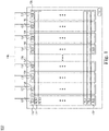
- FIG. 1 is a block diagram of an apparatus that includes a memory block 100 according to an embodiment of the present invention.
- apparatus may refer to, for example, an integrated circuit, a memory device, a memory system, an electronic device or system, a smart phone, a tablet, a computer, a server, etc.
- the memory block 100 includes a plurality of memory subblocks 102, a plurality of memory access lines 104, a plurality of select gate drain (SGD) control lines 106, a plurality of select gate source (SGS) control lines 120, and control unit 150.
- SGD control lines 106 may be associated with a respective memory subblock 102 and each of the SGS control lines 120 may be associated with a respective plurality of memory subblocks 102.
- each of the memory subblocks 102 may include a plurality of memory cells, such as non-volatile memory cells (e.g., NAND memory cells) that may be arranged in rows and/or columns.
- each of the memory cells may be a single-level cell (SLC) and/or may be a multi-level cell (MLC).
- SLC single-level cell
- MLC multi-level cell
- each memory cell may be programmed to distinct voltage states, each of which may correspond to a particular representation of binary data (e.g., single bit data 0, 1, multi-bit data 00, 01, 10, 11).
- each plurality of memory cells may include NAND memory cells
- each plurality of memory cells may be implemented using one or more NAND strings within each memory subblock 102.
- Each string may, for instance, include 32 non-volatile memory cells, or may include a greater or lesser number of memory cells, and memory cells of each string may share a common channel.
- Each memory subblock 102 may include any number of strings.
- each string may include a select gate drain (SGD) switch located at a first end of the string and a select gate source (SGS) switch located at a second end of the string opposite the first end.
- the SGD switch and the SGS switch may be implemented as transistors, as shown in the embodiments of Figs. 3a-3e .
- the memory cells of the string may be coupled in a series configuration between the SGD switch and the SGS switch.
- Each of the memory cells of the string may be coupled to a respective memory access line WL that may be used to access the memory cell.
- Memory access line drivers may provide various voltages to the memory access lines during memory operations, for example, during program operations, read operations, erase operations, as well as other memory operations.
- an SGD switch may be configured to selectively couple a string to a signal line VBL and an SGS switch may be configured to selectively couple a string to a source (e.g., source line) SRC.
- an SGD switch of a string included in a memory subblock 102 may be coupled to a respective SGD control line 106 associated with the memory subblock 102.
- Providing (e.g., asserting) a control signal (e.g., active control signal) on the SGD control line 106 may enable the respective SGD switch, thereby coupling the associated string to the signal line VBL.
- An SGD control line 106 providing a control signal to enable the SGD switch in this manner is described herein as an "active" SGD control line 106.
- an SGS switch of a memory subblock 102 may be coupled to an SGS line 120 associated with the memory subblock 102.
- Providing a control signal on the SGS line 120 may enable the SGS switch, thereby coupling the respective string to the source.
- An SGS control line 120 providing a control signal to enable the SGS switch in this manner is described herein as an "active" SGS control line 120.
- Providing (e.g., deasserting) a control signal (e.g., inactive control signal) on the SGD control line 106 may disable the respective SGD switch, thereby decoupling the associated string from the signal line VBL.
- An SGD control line 106 providing a control signal to disable the SGD switch in this manner is described herein as an "inactive" SGD control line 106.
- an SGS switch of a memory subblock 102 may be decoupled from an SGS line 120 associated with the memory subblock 102. Providing a control signal on the SGS line 120 may disable the SGS switch, thereby decoupling the respective string to the source.
- An SGS control line 120 providing a control signal to disable the SGS switch in this manner is described herein as an "inactive" SGS control line 120.
- control signals provided on respective SGD control lines 106 and SGS control lines 120, respectively, may be provided by control unit 150.
- the control unit 150 may be coupled to each of the SGD control lines 106 and the SGS control lines 120 and further may be configured to provide control signals to perform respective memory operations, described herein.
- the control unit 150 may be implemented in software and/or hardware, and may include any circuitry and/or logic required to perform operations.
- the control unit 150 may be included in the block 100 and in other examples, the control unit 150 may be located outside of the block 100, for instance, in a row decoder, an address decoder, control logic coupled to the block 100 and/or a controller (not shown in Fig. 1 ). In this manner, one or more portions of the circuitry and/or logic of the control unit 150 may be employed in a distributed configuration.
- Each SGD control line 106 may be associated with a respective memory subblock 102 of the block 100, each memory access line 104 may be associated with all memory subblocks 102 of the block 100, and/or each SGS control line 120 may be associated with a respective plurality of memory subblocks 102 of the block 100. Accordingly, each SGD control line 106 may be included, at least in part, in a respective memory subblock 102 and may be coupled to the SGD switch of the corresponding memory subblock 102. In this manner, each active SGD control line 106 may couple the string or strings of a respective memory subblock 102 to a set of signal lines shared, for instance, by each memory subblock 102.
- a memory access line 104 may be coupled to a memory cell of a string in each memory subblock 102 of the block 100. As a result, a memory access line 104 may span across all memory subblocks 102 of the block 100 and may be coupled to each memory cell of a particular row of memory cells.
- Each SGS control line 120 may span across an associated plurality of memory subblocks 102 and may be coupled to the SGS switches of the associated memory subblocks 102. In this manner, an active SGS control line 120 may couple strings of the associated plurality of memory subblocks 102 to a source SRC.
- SGS control lines 120 span memory subblocks 102 in a same direction as memory access lines 104 such that the memory access lines 104 and SGS control lines 120 are substantially parallel.
- SGD control lines 106 span memory subblocks in an orthogonal direction or other non-parallel directions relative to memory access lines 104.
- each SGS control line 120 may be associated with a respective plurality of memory subblocks 102, SGS switches coupled to an active SGS control line 120 may be enabled while SGS switches coupled to an inactive SGS control line 120 may be disabled. As will be explained in more detail below, by selectively enabling SGS switches in this manner, capacitive loading during one or more memory operations (e.g., read operations) may be reduced.
- any ratio of SGD control lines 106 to SGS control lines 120 and/or any ratio of memory access lines 104 to SGS control lines 120 may be achieved.
- the block 100 may include 32 memory subblocks 102 and each SGS control line 120 may be coupled to the SGS switches of strings for 4 memory subblocks 102 of the block 100. Accordingly, a 4:1 ratio of SGD control lines 106 to SGS control lines 120 and a 1:8 ratio of memory access lines 104 to SGS control lines 120 may be achieved.
- each SGS control line 120 may be coupled to the SGS switches of strings for 2, 8, 16, 32, 64, or any other number of memory subblocks 102.
- each SGS control line 120 may be coupled to the SGS switches of strings for a same number of memory subblocks 102, and that in other examples, SGS control lines 120 may be coupled to the SGS switches of strings for differing numbers of memory subblocks 102.
- a first SGS control line 120 may be coupled to the SGS switches of strings for 8 memory subblocks and a second SGS control line 120 may be coupled to the SGS switches of strings for 16 memory subblocks 120.
- memory operations may be performed on one or more selected memory subblocks 102 while all other memory subblocks 102 may be unselected.
- Performing a memory operation on one or more selected memory subblocks 102 may include selectively enabling SGD switches, SGS switches, and/or memory cells. Description of memory operations is made herein with respect to individual memory subblocks 102. It will be appreciated, however, that in some examples, one or more described operations may be applied simultaneously to any number of memory subblocks 102.
- SGD and SGS switches may be enabled by providing control signal on SGD control lines 106 or SGS control lines 120, respectively, and control signals provided in this manner may be provided by the control unit 150.
- SGD and SGS switches may be disabled.
- a low voltage such as ground potential (e.g., 0V)
- ground potential e.g. 0V
- erase operations may be implemented at a block level and accordingly one or more memory subblocks 102 may be erased simultaneously.
- all SGD lines 106 and all SGS lines 120 may have a low voltage during an erase operation to disable the SGD and SGS switches.
- program operations are performed on erased memory cells, and as a result, only memory cells of a memory subblock 102 intended to be adjusted from an erased voltage state to a different voltage state need be programmed.
- one or more selected rows of a memory subblock 102 may be programmed sequentially.
- signal lines associated with a cell to be programmed may be precharged to a first voltage (e.g., 0-1V) and signal lines associated with a cell not to be programmed may be precharged to a second voltage (2-3V) that may for instance, be higher than the first precharge voltage.
- a relatively high voltage (e.g., 15V) may be applied to a memory access line 104 corresponding to the row being programmed, while an intermediate voltage (e.g., 8V) may be applied to all other memory access lines 104.
- a magnitude of the intermediate voltage may be greater than a voltage of the voltage state having a highest magnitude to ensure that all memory cells of the memory subblock 102 are conductive.
- an SGD control line 106 associated with the selected memory subblock 102 may become active and SGD switches associated with strings to be programmed may be selectively enabled (while SGS switches may remain disabled) to program cells of the row. Because signal lines associated with cells not to be programmed have a higher precharge voltage, SGD switches associated with those signal lines may remain disabled and prevent programming of respective cells.
- the relatively high voltage applied to the memory access line 104 may be incrementally increased until each selected cell of the target row achieves a desired voltage level. During the programming operation, SGD and SGS switches of unselected memory subblocks 102 may be disabled.
- selected signal lines may be precharged to a voltage (e.g., 0.3V), and both the SGD and SGS switches of a memory subblock 102 may be enabled. Because each SGS control line 120 may be associated with a respective plurality of memory subblocks 102, SGS switches of one or more other memory subblocks 102 associated with the same SGS control line 120 may be enabled as well. Thereafter, a relatively low voltage (e.g., 0-2V) may be applied to a memory access line 104 associated with the row to be read, while an intermediate voltage (e.g., 8V) may be applied to all other memory access lines 104. In some examples, the relatively low voltage may be a voltage having a magnitude between voltage levels of particular voltage states.
- a relatively low voltage e.g., 0-2V
- an intermediate voltage e.g. 8V
- the relatively low voltage may be a voltage having a magnitude between voltage levels of particular voltage states.
- a magnitude of the intermediate voltage may be greater than a voltage of the voltage state having a highest magnitude to ensure that all memory cells of the memory subblock 102 are conductive.
- the SGD switches may be disabled (e.g., to electrically isolate selected signal lines), and the voltage of each selected signal line may be used to determine the voltage state of selected memory cells of the row. In some examples, the voltage of each selected signal line may be sensed to determine the voltage state of selected memory cells of the row prior to disabling the SGD switches.
- SGD switches of unselected memory subblocks 102 may be disabled, and SGS switches of all memory subblocks 102 not associated with the active SGS line 120 of the read operation may be disabled. In this manner, only the respective plurality of memory subblocks 102 associated with an active SGS line 120 may have enabled SGS switches. All other memory subblocks 102 may be associated with an inactive SGS line 120 and accordingly may have disabled SGS switches.
- the block 100 may be implemented in a three-dimensional arrangement.
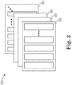
- Fig. 2 is a block diagram of a three-dimensional memory array 200 according to an embodiment of the present invention.
- the three-dimensional memory array 200 may include any number of blocks 202, one or more of which may be implemented using the block 100 of Fig 1 .
- the three-dimensional memory array 200 may include 32 blocks 202, or may include 64 blocks 202.
- memory cells of each block 202 may be accessed concurrently, simultaneously, and/or in an otherwise overlapping manner such that data may be read from, programmed to, and/or erased from multiple blocks 202 in accordance with one or more memory operations.
- the blocks 202 may be configured to share one or more components, such as signal lines and/or control lines.
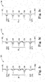
- Figs. 3a-3b illustrate schematic diagrams of NAND strings 300-310 during a program operation
- Figs. 3c-3e illustrate schematic diagrams of NAND strings 320-340 during a read operation.
- the NAND strings 300-340 may include respective SGD switches 302-342, respective SGS switches 304-344, and respective memory cells 306-346.
- each SGD switch may be located at a first end of a NAND string and may be configured to selectively couple the NAND string to a signal line VBL responsive to assertion of a control signal provided to an SGD switch.
- the control signal may be provided, for instance, on an SGD control line coupled to an SGD switch 302, such as an SGD control line 106 of Fig. 1 .
- each SGS switch may be located at a second end of the NAND string and may be configured to selectively couple the NAND string to a source SRC responsive to assertion of a control signal provided to an SGS switch.
- the control signal may be provided, for instance, on an SGS control line coupled to a SGS switch, such as an SGS control line 120 of Fig. 1 .
- Each of the memory cells may be coupled in a series configuration between respective SGD and SGS switches.
- Fig. 3a is a schematic diagram of a NAND string 300 of a selected memory subblock during a program operation according to an embodiment of the present invention.
- the SGD switch 302 may be enabled and the SGS switch 304 may be disabled.
- each cell 306 may provide (e.g., generate) a capacitive load between a gate of the cell 306 and the signal line VBL.
- Fig. 3b is a schematic diagram of a NAND string 310 of an unselected memory subblock during a program operation according to an embodiment of the present invention.
- the SGD switch 312 and the SGS switch 314 may be disabled. In this manner, voltage levels of the string may float.
- each cell 316 may provide a capacitive load between a gate of the cell 316 and the source SRC. The capacitive load, however, may be in series with a junction capacitance of the SGS switch 314.
- the capacitive load provided by cells 316 of the NAND string 310 may be in series with junction capacitance of the SGS switch 314, the capacitive load provided by the NAND string 300 may exceed the capacitive load provided by the NAND string 310 during program operations.
- Fig. 3c is a schematic diagram of a NAND string 320 of a selected memory subblock during a read operation according to an embodiment of the present invention.
- both the SGD switch 322 and the SGS switch 324 may be enabled simultaneously.
- each of the cells 326 may provide a load between a gate of the cell 326 and the source SRC.
- the load may include a capacitive load and a resistive load.
- the resistive load may include a channel resistance of the NAND string 320.
- Fig. 3d is a schematic diagram of a NAND string 330 of an unselected memory subblock during a read operation according to an embodiment of the present invention.
- the NAND string 330 while included in an unselected memory subblock, may, for instance, be associated with a same SGS control line 120 as the NAND string 320 of Fig. 3c . Accordingly, during a read operation, the NAND string 330 may be associated with an active SGS control line 120 and have an enabled SGS switch 334.
- each cell 336 may provide a capacitive load between a gate of the cell 306 and the source SRC.
- Fig. 3e is a schematic diagram of a NAND string 340 of an unselected memory subblock during a read operation according to an embodiment of the present invention.
- the NAND string 340 may not be associated with a same SGS control line as the selected NAND string 320 of Fig. 3c .
- the NAND string 340 may be associated with an inactive SGS control line 120 and the SGS switch 344 may be disabled.
- each cell 316 may provide a capacitive load between a gate of the cell 346 and the source SRC.
- the capacitive load may be in series with a junction capacitance of the SGS switch 344.
- the capacitive load provided by cells 346 of the NAND string 340 may be in series with junction capacitance of the SGS switch 344, the capacitive load provided by the NAND string 330 may exceed the capacitive load provided by the NAND string 340 during read operations.
- the overall capacitive load of the block 100 may be reduced during the read operation.
- design constraints may be relaxed and/or performance may be improved.
- capacitive loads driven by memory access line drivers may be reduced such that a smaller charge pump may be required for operation and/or memory access line voltages transition more quickly during operation.
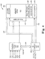
- Fig. 4 illustrates a memory 400 according to an embodiment of the present invention.
- the memory 400 includes a memory array 430 with a plurality of memory cells.
- the memory cells may be non-volatile memory cells, such as NAND flash cells, or may generally be any type of memory cells.
- the memory array 430 may include one or more memory blocks, such as a memory block 100 of Fig. 1 .
- the memory array 430 may be implemented as a three-dimensional memory array, such as the three-dimensional memory array 200 of Fig. 2 .
- Command signals, address signals, and write data signals may be provided to the memory 400 as sets of sequential input/output ("I/O") signals transmitted through an I/O bus 428. Similarly, read data signals may be provided from the memory 400 through the I/O bus 428.
- the I/O bus 428 is connected to an I/O control unit 420 that routes the signals between the I/O bus 428 and an internal data bus 422, an internal address bus 424, and an internal command bus 426.
- the memory 400 also includes a control logic unit 410 that receives a number of control signals either externally or through the internal command bus 426 to control the operation of the memory 400.
- the internal address bus 424 applies block-row and/or subblock-row address signals to a row decoder 440 and column address signals to a column decoder 450.
- the row decoder 440 and column decoder 450 may be used to select blocks of memory or memory cells for memory operations, for example, read, program, and erase operations.
- the column decoder 450 may enable write data signals to be applied to columns of memory corresponding to the column address signals and allow read data signals to be coupled from columns corresponding to the column address signals.
- Read, program, erase circuits 468 coupled to the memory array 430 receive control signals from the control logic unit 410 and include voltage generators (e.g., charge pumps) for generating various pumped voltages for read, program and erase operations.
- voltage generators e.g., charge pumps
- the I/O control unit 420 routes write data signals to a cache register 470.
- the write data signals are stored in the cache register 470 in successive sets each having a size corresponding to the width of the I/O bus 428.
- the cache register 470 sequentially stores the sets of write data signals for an entire row or page of memory cells in the memory array 430. All of the stored write data signals are then used to program a row or page of memory cells in the memory array 430 selected by the block-row address or subblock-row address coupled through the internal address bus 424.
- data signals from a row or block of memory cells selected by the block-row address coupled through the internal address bus 424 are stored in a data register 480.
- Sets of data signals corresponding in size to the width of the I/O bus 428 are then sequentially transferred through the I/O control unit 420 from the data register 480 to the I/O bus 428.
Description
- Memory cell density, such as that of non-volatile memory, has been improved significantly in an effort to achieve greater storage capacity, while not significantly increasing cost or memory footprint. One widely adopted solution has been to implement memory cells in three-dimensions, for instance, using vertically oriented NAND strings.
- Implementing memories in this manner has presented challenges, however. By way of example, as a result of three-dimensional implementation, block sizes have increased, and as a corollary, capacitive and resistive loads generated during operation have increased as well.
-
US 2012/069663 A1 describes a control circuit configured to execute an erasing operation on a selected cell unit in a selected memory block. In the erasing operation, the control circuit raises the voltage of the bodies of the first memory transistors included in the selected cell unit to a first voltage, sets the voltage of the bodies of the first memory transistors included in the non-selected cell unit to a second voltage lower than the first voltage, and applies a third voltage equal to or lower than the second voltage to the gates of the first memory transistors included in the selected cell unit and the non-selected cell unit. -
US 2007/263462 A1 describes non-volatile memory devices utilizing a modified NAND architecture where ends of the NAND string of memory cells are selectively coupled to different bit lines. - The invention is set out in the appended set of claims.
-
-
Fig. 1 is a schematic block diagram of an apparatus including a memory block according to an embodiment of the present invention. -
Fig. 2 is a block diagram of a three-dimensional memory array according to an embodiment of the present invention. -
Fig. 3a is a schematic diagram of a NAND string of a selected subblock during a program operation according to an embodiment of the present invention. -
Fig. 3b is a schematic diagram of a NAND string of an unselected subblock during a program operation according to an embodiment of the present invention. -
Fig. 3c is a schematic diagram of a NAND string of a selected subblock during a read operation according to an embodiment of the present invention. -
Fig. 3d is a schematic diagram of a NAND string of an unselected subblock during a read operation according to an embodiment of the present invention. -
Fig. 3e is a schematic diagram of a NAND string of an unselected subblock during a read operation according to an embodiment of the present invention. -
Fig. 4 is a block diagram of a memory according to an embodiment of the present invention. - Apparatuses and methods for segmented SGS lines are described herein. Certain details are set forth below to provide a sufficient understanding of embodiments of the invention. However, it will be clear to one having skill in the art that embodiments of the invention may be practiced without these particular details. Moreover, the particular embodiments of the present invention described herein are provided by way of example and should not be used to limit the scope of the invention to these particular embodiments. In other instances, well-known circuits, control signals, timing protocols, and software operations have not been shown in detail in order to avoid unnecessarily obscuring the invention.
-
Figure 1 is a block diagram of an apparatus that includes amemory block 100 according to an embodiment of the present invention. As used herein, apparatus may refer to, for example, an integrated circuit, a memory device, a memory system, an electronic device or system, a smart phone, a tablet, a computer, a server, etc. Thememory block 100 includes a plurality ofmemory subblocks 102, a plurality ofmemory access lines 104, a plurality of select gate drain (SGD)control lines 106, a plurality of select gate source (SGS)control lines 120, andcontrol unit 150. Each of theSGD control lines 106 may be associated with arespective memory subblock 102 and each of theSGS control lines 120 may be associated with a respective plurality ofmemory subblocks 102. - In some examples, each of the
memory subblocks 102 may include a plurality of memory cells, such as non-volatile memory cells (e.g., NAND memory cells) that may be arranged in rows and/or columns. In some examples, each of the memory cells may be a single-level cell (SLC) and/or may be a multi-level cell (MLC). In this manner, each memory cell may be programmed to distinct voltage states, each of which may correspond to a particular representation of binary data (e.g.,single bit data multi-bit data 00, 01, 10, 11). Because each plurality of memory cells may include NAND memory cells, each plurality of memory cells may be implemented using one or more NAND strings within eachmemory subblock 102. Each string may, for instance, include 32 non-volatile memory cells, or may include a greater or lesser number of memory cells, and memory cells of each string may share a common channel. Eachmemory subblock 102 may include any number of strings. - With reference to
Figs. 3a-3e , each string may include a select gate drain (SGD) switch located at a first end of the string and a select gate source (SGS) switch located at a second end of the string opposite the first end. The SGD switch and the SGS switch may be implemented as transistors, as shown in the embodiments ofFigs. 3a-3e . The memory cells of the string may be coupled in a series configuration between the SGD switch and the SGS switch. Each of the memory cells of the string may be coupled to a respective memory access line WL that may be used to access the memory cell. Memory access line drivers may provide various voltages to the memory access lines during memory operations, for example, during program operations, read operations, erase operations, as well as other memory operations. - In some examples, an SGD switch may be configured to selectively couple a string to a signal line VBL and an SGS switch may be configured to selectively couple a string to a source (e.g., source line) SRC. By way of example, an SGD switch of a string included in a
memory subblock 102 may be coupled to a respectiveSGD control line 106 associated with thememory subblock 102. Providing (e.g., asserting) a control signal (e.g., active control signal) on theSGD control line 106 may enable the respective SGD switch, thereby coupling the associated string to the signal line VBL. AnSGD control line 106 providing a control signal to enable the SGD switch in this manner is described herein as an "active"SGD control line 106. Similarly, an SGS switch of amemory subblock 102 may be coupled to anSGS line 120 associated with thememory subblock 102. Providing a control signal on theSGS line 120 may enable the SGS switch, thereby coupling the respective string to the source. AnSGS control line 120 providing a control signal to enable the SGS switch in this manner is described herein as an "active"SGS control line 120. Providing (e.g., deasserting) a control signal (e.g., inactive control signal) on theSGD control line 106 may disable the respective SGD switch, thereby decoupling the associated string from the signal line VBL. AnSGD control line 106 providing a control signal to disable the SGD switch in this manner is described herein as an "inactive"SGD control line 106. Similarly, an SGS switch of amemory subblock 102 may be decoupled from anSGS line 120 associated with thememory subblock 102. Providing a control signal on theSGS line 120 may disable the SGS switch, thereby decoupling the respective string to the source. AnSGS control line 120 providing a control signal to disable the SGS switch in this manner is described herein as an "inactive"SGS control line 120. - In some examples, control signals provided on respective
SGD control lines 106 andSGS control lines 120, respectively, may be provided bycontrol unit 150. Thecontrol unit 150 may be coupled to each of theSGD control lines 106 and theSGS control lines 120 and further may be configured to provide control signals to perform respective memory operations, described herein. Thecontrol unit 150 may be implemented in software and/or hardware, and may include any circuitry and/or logic required to perform operations. In some examples, thecontrol unit 150 may be included in theblock 100 and in other examples, thecontrol unit 150 may be located outside of theblock 100, for instance, in a row decoder, an address decoder, control logic coupled to theblock 100 and/or a controller (not shown inFig. 1 ). In this manner, one or more portions of the circuitry and/or logic of thecontrol unit 150 may be employed in a distributed configuration. - Each
SGD control line 106 may be associated with arespective memory subblock 102 of theblock 100, eachmemory access line 104 may be associated with allmemory subblocks 102 of theblock 100, and/or eachSGS control line 120 may be associated with a respective plurality ofmemory subblocks 102 of theblock 100. Accordingly, eachSGD control line 106 may be included, at least in part, in arespective memory subblock 102 and may be coupled to the SGD switch of thecorresponding memory subblock 102. In this manner, each activeSGD control line 106 may couple the string or strings of arespective memory subblock 102 to a set of signal lines shared, for instance, by eachmemory subblock 102. Amemory access line 104 may be coupled to a memory cell of a string in eachmemory subblock 102 of theblock 100. As a result, amemory access line 104 may span across allmemory subblocks 102 of theblock 100 and may be coupled to each memory cell of a particular row of memory cells. EachSGS control line 120 may span across an associated plurality ofmemory subblocks 102 and may be coupled to the SGS switches of the associatedmemory subblocks 102. In this manner, an activeSGS control line 120 may couple strings of the associated plurality ofmemory subblocks 102 to a source SRC.SGS control lines 120span memory subblocks 102 in a same direction asmemory access lines 104 such that thememory access lines 104 andSGS control lines 120 are substantially parallel.SGD control lines 106 span memory subblocks in an orthogonal direction or other non-parallel directions relative to memory access lines 104. - Because each
SGS control line 120 may be associated with a respective plurality ofmemory subblocks 102, SGS switches coupled to an activeSGS control line 120 may be enabled while SGS switches coupled to an inactiveSGS control line 120 may be disabled. As will be explained in more detail below, by selectively enabling SGS switches in this manner, capacitive loading during one or more memory operations (e.g., read operations) may be reduced. - In some examples, any ratio of
SGD control lines 106 toSGS control lines 120 and/or any ratio ofmemory access lines 104 toSGS control lines 120 may be achieved. By way of example, theblock 100 may include 32memory subblocks 102 and eachSGS control line 120 may be coupled to the SGS switches of strings for 4memory subblocks 102 of theblock 100. Accordingly, a 4:1 ratio ofSGD control lines 106 toSGS control lines 120 and a 1:8 ratio ofmemory access lines 104 toSGS control lines 120 may be achieved. In other examples, eachSGS control line 120 may be coupled to the SGS switches of strings for 2, 8, 16, 32, 64, or any other number ofmemory subblocks 102. It will be appreciated that in some examples, eachSGS control line 120 may be coupled to the SGS switches of strings for a same number ofmemory subblocks 102, and that in other examples,SGS control lines 120 may be coupled to the SGS switches of strings for differing numbers ofmemory subblocks 102. A firstSGS control line 120, for instance, may be coupled to the SGS switches of strings for 8 memory subblocks and a secondSGS control line 120 may be coupled to the SGS switches of strings for 16memory subblocks 120. - Generally, memory operations (e.g., read operations, program operations, erase operations) may be performed on one or more selected
memory subblocks 102 while allother memory subblocks 102 may be unselected. Performing a memory operation on one or more selectedmemory subblocks 102 may include selectively enabling SGD switches, SGS switches, and/or memory cells. Description of memory operations is made herein with respect toindividual memory subblocks 102. It will be appreciated, however, that in some examples, one or more described operations may be applied simultaneously to any number ofmemory subblocks 102. Moreover, reference is made herein to selectively enabling SGD and SGS switches to perform memory operations. As described, SGD and SGS switches may be enabled by providing control signal onSGD control lines 106 orSGS control lines 120, respectively, and control signals provided in this manner may be provided by thecontrol unit 150. - In an erase operation, for example, SGD and SGS switches may be disabled. For each row, a low voltage, such as ground potential (e.g., 0V), may be applied to the
memory access line 104 associated with the row, thereby erasing the voltage state of each memory cell. In some examples, erase operations may be implemented at a block level and accordingly one ormore memory subblocks 102 may be erased simultaneously. As a result, allSGD lines 106 and allSGS lines 120 may have a low voltage during an erase operation to disable the SGD and SGS switches. - Typically, program operations are performed on erased memory cells, and as a result, only memory cells of a
memory subblock 102 intended to be adjusted from an erased voltage state to a different voltage state need be programmed. In an example programming operation, one or more selected rows of amemory subblock 102 may be programmed sequentially. By way of example, for each selected row, signal lines associated with a cell to be programmed may be precharged to a first voltage (e.g., 0-1V) and signal lines associated with a cell not to be programmed may be precharged to a second voltage (2-3V) that may for instance, be higher than the first precharge voltage. A relatively high voltage (e.g., 15V) may be applied to amemory access line 104 corresponding to the row being programmed, while an intermediate voltage (e.g., 8V) may be applied to all other memory access lines 104. A magnitude of the intermediate voltage may be greater than a voltage of the voltage state having a highest magnitude to ensure that all memory cells of thememory subblock 102 are conductive. Thereafter, anSGD control line 106 associated with the selectedmemory subblock 102 may become active and SGD switches associated with strings to be programmed may be selectively enabled (while SGS switches may remain disabled) to program cells of the row. Because signal lines associated with cells not to be programmed have a higher precharge voltage, SGD switches associated with those signal lines may remain disabled and prevent programming of respective cells. In some examples, the relatively high voltage applied to thememory access line 104 may be incrementally increased until each selected cell of the target row achieves a desired voltage level. During the programming operation, SGD and SGS switches ofunselected memory subblocks 102 may be disabled. - In an example read operation, selected signal lines may be precharged to a voltage (e.g., 0.3V), and both the SGD and SGS switches of a
memory subblock 102 may be enabled. Because eachSGS control line 120 may be associated with a respective plurality ofmemory subblocks 102, SGS switches of one or moreother memory subblocks 102 associated with the sameSGS control line 120 may be enabled as well. Thereafter, a relatively low voltage (e.g., 0-2V) may be applied to amemory access line 104 associated with the row to be read, while an intermediate voltage (e.g., 8V) may be applied to all other memory access lines 104. In some examples, the relatively low voltage may be a voltage having a magnitude between voltage levels of particular voltage states. Further, as described, a magnitude of the intermediate voltage may be greater than a voltage of the voltage state having a highest magnitude to ensure that all memory cells of thememory subblock 102 are conductive. The SGD switches may be disabled (e.g., to electrically isolate selected signal lines), and the voltage of each selected signal line may be used to determine the voltage state of selected memory cells of the row. In some examples, the voltage of each selected signal line may be sensed to determine the voltage state of selected memory cells of the row prior to disabling the SGD switches. During the read operation, SGD switches ofunselected memory subblocks 102 may be disabled, and SGS switches of allmemory subblocks 102 not associated with theactive SGS line 120 of the read operation may be disabled. In this manner, only the respective plurality ofmemory subblocks 102 associated with anactive SGS line 120 may have enabled SGS switches. Allother memory subblocks 102 may be associated with aninactive SGS line 120 and accordingly may have disabled SGS switches. - In some examples, the
block 100 may be implemented in a three-dimensional arrangement.Fig. 2 is a block diagram of a three-dimensional memory array 200 according to an embodiment of the present invention. The three-dimensional memory array 200 may include any number ofblocks 202, one or more of which may be implemented using theblock 100 ofFig 1 . By way of example, the three-dimensional memory array 200 may include 32blocks 202, or may include 64blocks 202. In some examples, memory cells of eachblock 202 may be accessed concurrently, simultaneously, and/or in an otherwise overlapping manner such that data may be read from, programmed to, and/or erased frommultiple blocks 202 in accordance with one or more memory operations. In other examples, theblocks 202 may be configured to share one or more components, such as signal lines and/or control lines. -
Figs. 3a-3b illustrate schematic diagrams of NAND strings 300-310 during a program operation andFigs. 3c-3e illustrate schematic diagrams of NAND strings 320-340 during a read operation. The NAND strings 300-340 may include respective SGD switches 302-342, respective SGS switches 304-344, and respective memory cells 306-346. As described, each SGD switch may be located at a first end of a NAND string and may be configured to selectively couple the NAND string to a signal line VBL responsive to assertion of a control signal provided to an SGD switch. The control signal may be provided, for instance, on an SGD control line coupled to anSGD switch 302, such as anSGD control line 106 ofFig. 1 . Similarly, each SGS switch may be located at a second end of the NAND string and may be configured to selectively couple the NAND string to a source SRC responsive to assertion of a control signal provided to an SGS switch. The control signal may be provided, for instance, on an SGS control line coupled to a SGS switch, such as anSGS control line 120 ofFig. 1 . Each of the memory cells may be coupled in a series configuration between respective SGD and SGS switches. -
Fig. 3a is a schematic diagram of aNAND string 300 of a selected memory subblock during a program operation according to an embodiment of the present invention. As described, during the program operation, theSGD switch 302 may be enabled and theSGS switch 304 may be disabled. As a result, during a program operation, eachcell 306 may provide (e.g., generate) a capacitive load between a gate of thecell 306 and the signal line VBL. -
Fig. 3b is a schematic diagram of aNAND string 310 of an unselected memory subblock during a program operation according to an embodiment of the present invention. As described, during the program operation, theSGD switch 312 and theSGS switch 314 may be disabled. In this manner, voltage levels of the string may float. As a result, during the program operation, eachcell 316 may provide a capacitive load between a gate of thecell 316 and the source SRC. The capacitive load, however, may be in series with a junction capacitance of theSGS switch 314. Because the capacitive load provided bycells 316 of theNAND string 310 may be in series with junction capacitance of theSGS switch 314, the capacitive load provided by theNAND string 300 may exceed the capacitive load provided by theNAND string 310 during program operations. -
Fig. 3c is a schematic diagram of aNAND string 320 of a selected memory subblock during a read operation according to an embodiment of the present invention. As described, during the read operation, both theSGD switch 322 and theSGS switch 324 may be enabled simultaneously. As a result, each of thecells 326 may provide a load between a gate of thecell 326 and the source SRC. The load may include a capacitive load and a resistive load. The resistive load may include a channel resistance of theNAND string 320. -
Fig. 3d is a schematic diagram of aNAND string 330 of an unselected memory subblock during a read operation according to an embodiment of the present invention. TheNAND string 330, while included in an unselected memory subblock, may, for instance, be associated with a sameSGS control line 120 as theNAND string 320 ofFig. 3c . Accordingly, during a read operation, theNAND string 330 may be associated with an activeSGS control line 120 and have an enabledSGS switch 334. As a result, during the read operation, eachcell 336 may provide a capacitive load between a gate of thecell 306 and the source SRC. -
Fig. 3e is a schematic diagram of aNAND string 340 of an unselected memory subblock during a read operation according to an embodiment of the present invention. In contrast to theNAND string 330 ofFig. 3d , theNAND string 340 may not be associated with a same SGS control line as the selectedNAND string 320 ofFig. 3c . Accordingly, during the read operation, theNAND string 340 may be associated with an inactiveSGS control line 120 and the SGS switch 344 may be disabled. As a result, eachcell 316 may provide a capacitive load between a gate of thecell 346 and the source SRC. The capacitive load, however, may be in series with a junction capacitance of the SGS switch 344. Because the capacitive load provided bycells 346 of theNAND string 340 may be in series with junction capacitance of the SGS switch 344, the capacitive load provided by theNAND string 330 may exceed the capacitive load provided by theNAND string 340 during read operations. - With reference to
Fig. 1 , by reducing the number ofmemory subblocks 102 having enabled SGS switches during a read operation (e.g., less than allmemory subblocks 102 of the block 100), the overall capacitive load of theblock 100 may be reduced during the read operation. In this manner, design constraints may be relaxed and/or performance may be improved. By way of example, capacitive loads driven by memory access line drivers (not shown), may be reduced such that a smaller charge pump may be required for operation and/or memory access line voltages transition more quickly during operation. -
Fig. 4 illustrates amemory 400 according to an embodiment of the present invention. Thememory 400 includes amemory array 430 with a plurality of memory cells. The memory cells may be non-volatile memory cells, such as NAND flash cells, or may generally be any type of memory cells. In some examples, thememory array 430 may include one or more memory blocks, such as amemory block 100 ofFig. 1 . Moreover, thememory array 430 may be implemented as a three-dimensional memory array, such as the three-dimensional memory array 200 ofFig. 2 . - Command signals, address signals, and write data signals may be provided to the
memory 400 as sets of sequential input/output ("I/O") signals transmitted through an I/O bus 428. Similarly, read data signals may be provided from thememory 400 through the I/O bus 428. The I/O bus 428 is connected to an I/O control unit 420 that routes the signals between the I/O bus 428 and aninternal data bus 422, aninternal address bus 424, and aninternal command bus 426. Thememory 400 also includes acontrol logic unit 410 that receives a number of control signals either externally or through theinternal command bus 426 to control the operation of thememory 400. - The
internal address bus 424 applies block-row and/or subblock-row address signals to arow decoder 440 and column address signals to acolumn decoder 450. Therow decoder 440 andcolumn decoder 450 may be used to select blocks of memory or memory cells for memory operations, for example, read, program, and erase operations. Thecolumn decoder 450 may enable write data signals to be applied to columns of memory corresponding to the column address signals and allow read data signals to be coupled from columns corresponding to the column address signals. - In response to the memory commands decoded by the
control logic unit 410, the memory cells in thememory array 430 are read, programmed, and/or erased. Read, program, erasecircuits 468 coupled to thememory array 430 receive control signals from thecontrol logic unit 410 and include voltage generators (e.g., charge pumps) for generating various pumped voltages for read, program and erase operations. - After the row address signals have been applied to the
internal address bus 424, the I/O control unit 420 routes write data signals to acache register 470. The write data signals are stored in thecache register 470 in successive sets each having a size corresponding to the width of the I/O bus 428. The cache register 470 sequentially stores the sets of write data signals for an entire row or page of memory cells in thememory array 430. All of the stored write data signals are then used to program a row or page of memory cells in thememory array 430 selected by the block-row address or subblock-row address coupled through theinternal address bus 424. In a similar manner, during a read operation, data signals from a row or block of memory cells selected by the block-row address coupled through theinternal address bus 424 are stored in adata register 480. Sets of data signals corresponding in size to the width of the I/O bus 428 are then sequentially transferred through the I/O control unit 420 from the data register 480 to the I/O bus 428.
Claims (7)
- An apparatus, comprising:a first plurality of memory subblocks (102) of a memory block of a three-dimensional memory array;a second plurality of memory subblocks (102) of the memory block, wherein each memory subblock (102) of the first and second plurality of memory subblocks includes a plurality of strings, wherein each string of the plurality of strings includes:a select gate drain switch coupled to a signal line of a set of signal lines shared by each memory subblock (102) of the first and second pluralities of memory subblocks; anda select gate source switch coupled to a source line;a first select gate source control line (120) associated with the first plurality of memory subblocks, the first select gate source control line coupled to the select gate source switches of the plurality of strings of the first plurality of memory subblocks, wherein the select gate source switches of the plurality of strings of the first plurality of memory subblocks are configured to selectively couple the plurality of strings of the first plurality of memory subblocks to the source line responsive to a first control signal on the first select gate source control line;a second select gate source control line (120) associated with the second plurality of memory subblocks, the second select gate source control line coupled to the select gate source switches of the plurality of strings of the second plurality of memory subblocks, wherein the select gate source switches of the plurality of strings of the second plurality of memory subblocks are configured to selectively couple the plurality of strings of the second plurality of memory subblocks to the source line responsive to a second control signal on the second select gate source control line;a plurality of select gate drain control lines (106), each select gate drain control line of the plurality of select gate drain control lines associated with a respective memory subblock (102) of the first and second pluralities of memory subblocks and coupled to the select gate drain switches of the plurality of strings of the respective memory subblock, and wherein the select gate drain switches of the plurality of strings of the respective memory subblock are each configured to selectively couple an associated string of the plurality of strings of the respective memory subblock to the respective signal line of the set of signal lines shared by each memory subblock (102) responsive to a third control signal on the respective select gate drain control line; anda plurality of memory access lines (104), each memory access line of the plurality of memory access lines associated with each memory subblock of the first plurality of memory subblocks and each memory subblock of the second plurality of memory subblocks, and wherein each memory access line of the plurality of memory access lines is coupled to a plurality of memory cells of each memory subblock of the first plurality of memory subblocks and a plurality of memory cells of each memory subblock of the second plurality of memory subblocks,wherein the first select gate source control line and the second select gate source control line span the first plurality of memory subblocks and the second plurality of memory subblocks, respectively in a same direction as the plurality of memory access lines, andwherein the plurality of select gate drain control lines span the respective memory subblocks of the first and second pluralities of the memory subblocks in a non-parallel direction relative to the plurality of memory access lines.
- The apparatus of claim 1, further comprising:
a control unit (150) configured to selectively enable the select gate source switches of the plurality of strings of the first plurality of memory subblocks. - The apparatus of claim 1, wherein the first select gate source control line (120) is configured to be active responsive to a read operation being performed on a memory subblock (102) of the first plurality of memory subblocks and the second gate source control line (120) is configured to be inactive responsive to the read operation being performed on the memory subblock of the first plurality of memory subblocks.
- The apparatus of claim 1, wherein the memory subblocks (102) of the plurality of strings of the first plurality of memory subblocks and the memory subblocks (102) of the plurality of strings of the second plurality of memory subblocks include a same number of memory subblocks.
- The apparatus of claim 1, wherein the apparatus is included in a memory.
- A method, comprising:providing, during a read operation, a first control signal on a first select gate source control line (120) to enable select gate source switches of a first plurality of memory subblocks (102) of a block of a three-dimensional memory array, coupling a plurality of strings for each memory subblock of the first plurality of memory subblocks of the block to a source line;providing, during the read operation, a second control signal on a second select gate source control line (120) to disable select gate source switches of a second plurality of memory subblocks (102) of the block, thereby decoupling a plurality of strings for each memory subblock of the second plurality of memory subblocks of the block from the source line;providing, during the read operation, a third control signal on a first select gate drain control line (106) to selectively enable a respective select gate drain switch of a first memory subblock (102) of the first plurality of memory subblocks, thereby coupling an associated string of a plurality of strings of the first memory subblock to a respective signal line of a set of signal lines shared by each memory subblock (102) of the first and second pluralities of memory subblocks; andproviding, during the read operation, a fourth control signal on a second select gate drain control line (106) to selectively disable a respective select gate drain switch of a second memory subblock (102) of the first plurality of memory subblocks, thereby decoupling an associated string of a plurality of strings of the second memory subblock from the respective signal line,wherein the first select gate source control line and the second select gate source control line span the first plurality of memory subblocks and the second plurality of memory subblocks, respectively in a same direction as a plurality of memory access lines, wherein each memory access line of the plurality of memory access lines is associated with each memory subblock of the first plurality of memory subblocks and each memory subblock of the second plurality of memory subblocks, and wherein each memory access line of the plurality of memory access lines is coupled to a plurality of memory cells of each memory subblock of the first plurality of memory subblocks and a plurality of memory cells of each memory subblock of the second plurality of memory subblocks, andwherein the first select gate drain control line and the second select gate drain control line span the respective memory subblocks of the first and second pluralities of the memory subblocks in a non-parallel direction relative to the plurality of memory access lines.
- The method of claim 6, wherein providing, during the read operation, the second control signal on the second select gate source control line (120) to disable select gate source switches of the second plurality of memory subblocks (102) of the block causes coupling of a capacitive load between a gate of a corresponding memory cell and the source line.
Applications Claiming Priority (2)
| Application Number | Priority Date | Filing Date | Title |
|---|---|---|---|
| US14/518,807 US9460792B2 (en) | 2014-10-20 | 2014-10-20 | Apparatuses and methods for segmented SGS lines |
| PCT/US2015/054412 WO2016064579A1 (en) | 2014-10-20 | 2015-10-07 | Apparatuses and methods for segmented sgs lines |
Publications (3)
| Publication Number | Publication Date |
|---|---|
| EP3210209A1 EP3210209A1 (en) | 2017-08-30 |
| EP3210209A4 EP3210209A4 (en) | 2018-05-16 |
| EP3210209B1 true EP3210209B1 (en) | 2022-05-18 |
Family
ID=55749560
Family Applications (1)
| Application Number | Title | Priority Date | Filing Date |
|---|---|---|---|
| EP15852706.9A Active EP3210209B1 (en) | 2014-10-20 | 2015-10-07 | Apparatuses and methods for segmented sgs lines |
Country Status (8)
| Country | Link |
|---|---|
| US (4) | US9460792B2 (en) |
| EP (1) | EP3210209B1 (en) |
| JP (1) | JP6491330B2 (en) |
| KR (1) | KR102029874B1 (en) |
| CN (1) | CN107077879B (en) |
| SG (1) | SG11201702480RA (en) |
| TW (2) | TWI590251B (en) |
| WO (1) | WO2016064579A1 (en) |
Families Citing this family (14)
| Publication number | Priority date | Publication date | Assignee | Title |
|---|---|---|---|---|
| KR102272238B1 (en) * | 2014-09-02 | 2021-07-06 | 삼성전자주식회사 | Nonvolatile memory device and programming method thereof |
| US9460792B2 (en) | 2014-10-20 | 2016-10-04 | Micron Technology, Inc. | Apparatuses and methods for segmented SGS lines |
| US9595339B2 (en) | 2014-10-20 | 2017-03-14 | Micron Technology, Inc. | Apparatuses and methods for reducing read disturb |
| US11636325B2 (en) | 2018-10-24 | 2023-04-25 | Macronix International Co., Ltd. | In-memory data pooling for machine learning |
| US11562229B2 (en) | 2018-11-30 | 2023-01-24 | Macronix International Co., Ltd. | Convolution accelerator using in-memory computation |
| US11934480B2 (en) | 2018-12-18 | 2024-03-19 | Macronix International Co., Ltd. | NAND block architecture for in-memory multiply-and-accumulate operations |
| US10878907B1 (en) * | 2019-06-05 | 2020-12-29 | Sandisk Technologies Llc | Sub-block size reduction for 3D non-volatile memory |
| US11239248B2 (en) | 2019-11-18 | 2022-02-01 | Micron Technology, Inc. | Microelectronic devices including stair step structures, and related electronic devices and methods |
| US11081162B1 (en) | 2020-02-24 | 2021-08-03 | Sandisk Technologies Llc | Source side precharge and boosting improvement for reverse order program |
| US11476266B2 (en) | 2020-02-24 | 2022-10-18 | Micron Technology, Inc. | Microelectronic devices including staircase structures, and related memory devices, electronic systems, and methods |
| US11417673B2 (en) | 2020-06-22 | 2022-08-16 | Micron Technology, Inc. | Microelectronic devices including stair step structures, and related memory devices, electronic systems, and methods |
| US11830815B2 (en) | 2020-08-28 | 2023-11-28 | Micron Technology, Inc. | Microelectronic devices including stair step structures, and related electronic systems and methods |
| US11637178B2 (en) | 2020-10-23 | 2023-04-25 | Micron Technology, Inc. | Microelectronic devices including isolation structures neighboring staircase structures, and related memory devices, electronic systems, and methods |
| US11700727B2 (en) | 2020-12-03 | 2023-07-11 | Micron Technology, Inc. | Microelectronic device structures including tiered stacks comprising staggered block structures separated by slot structures, and related electronic systems and methods |
Family Cites Families (42)
| Publication number | Priority date | Publication date | Assignee | Title |
|---|---|---|---|---|
| JPH11177071A (en) | 1997-12-11 | 1999-07-02 | Toshiba Corp | Nonvolatile semiconductor storage device |
| US7257132B1 (en) | 1998-02-26 | 2007-08-14 | Hitachi, Ltd. | Receiver set, information apparatus and receiving system |
| US6925008B2 (en) * | 2001-09-29 | 2005-08-02 | Kabushiki Kaisha Toshiba | Non-volatile semiconductor memory device with a memory unit including not more than two memory cell transistors |
| US7148538B2 (en) | 2003-12-17 | 2006-12-12 | Micron Technology, Inc. | Vertical NAND flash memory array |
| US7457156B2 (en) | 2004-09-02 | 2008-11-25 | Micron Technology, Inc. | NAND flash depletion cell structure |
| US7450422B2 (en) | 2006-05-11 | 2008-11-11 | Micron Technology, Inc. | NAND architecture memory devices and operation |
| US8279704B2 (en) * | 2006-07-31 | 2012-10-02 | Sandisk 3D Llc | Decoder circuitry providing forward and reverse modes of memory array operation and method for biasing same |
| US7778086B2 (en) * | 2007-01-25 | 2010-08-17 | Micron Technology, Inc. | Erase operation control sequencing apparatus, systems, and methods |
| JP2009266944A (en) | 2008-04-23 | 2009-11-12 | Toshiba Corp | Three-dimensional stacked nonvolatile semiconductor memory |
| US7903461B2 (en) | 2008-09-22 | 2011-03-08 | Micron Technology, Inc. | Sensing for memory read and program verify operations in a non-volatile memory device |
| KR101527195B1 (en) * | 2009-02-02 | 2015-06-10 | 삼성전자주식회사 | Nonvolatile memory device having vertical structure |
| JP2011054267A (en) * | 2009-09-03 | 2011-03-17 | Samsung Electronics Co Ltd | Nonvolatile memory device having vertical structure and method of operating the same |
| JP2011060377A (en) * | 2009-09-10 | 2011-03-24 | Toshiba Corp | Semiconductor memory device and writing control method thereof |
| KR101682666B1 (en) | 2010-08-11 | 2016-12-07 | 삼성전자주식회사 | Nonvolatile memory devicwe, channel boosting method thereof, programming method thereof, and memory system having the same |
| JP2012069606A (en) * | 2010-09-21 | 2012-04-05 | Toshiba Corp | Nonvolatile semiconductor memory device |
| JP2012069205A (en) | 2010-09-22 | 2012-04-05 | Toshiba Corp | Nonvolatile semiconductor memory |
| US8681555B2 (en) | 2011-01-14 | 2014-03-25 | Micron Technology, Inc. | Strings of memory cells having string select gates, memory devices incorporating such strings, and methods of accessing and forming the same |
| JP2012216269A (en) | 2011-04-01 | 2012-11-08 | Toshiba Corp | Nonvolatile semiconductor storage device |
| KR101293224B1 (en) * | 2011-04-01 | 2013-08-05 | (주)아토솔루션 | Data writing method, memory, and memory writing system |
| JP2013004123A (en) | 2011-06-14 | 2013-01-07 | Toshiba Corp | Nonvolatile semiconductor memory device |
| JP2013058276A (en) | 2011-09-07 | 2013-03-28 | Toshiba Corp | Semiconductor memory device |
| WO2013043182A1 (en) * | 2011-09-22 | 2013-03-28 | Intel Corporation | Nand memory array with mismatched cell and bitline pitch |
| US8947934B2 (en) | 2011-12-29 | 2015-02-03 | Micron Technology, Inc. | Sharing local control lines across multiple planes in a memory device |
| US8670285B2 (en) | 2012-02-02 | 2014-03-11 | Sandisk Technologies Inc. | Reducing weak-erase type read disturb in 3D non-volatile memory |
| JP2013214553A (en) | 2012-03-30 | 2013-10-17 | Toshiba Corp | Method for manufacturing semiconductor device and semiconductor device |
| US8923048B2 (en) | 2012-04-13 | 2014-12-30 | Sandisk Technologies Inc. | 3D non-volatile storage with transistor decoding structure |
| US9171626B2 (en) * | 2012-07-30 | 2015-10-27 | Micron Technology, Inc.. | Memory devices and programming memory arrays thereof |
| US10541029B2 (en) | 2012-08-01 | 2020-01-21 | Micron Technology, Inc. | Partial block memory operations |
| US9299439B2 (en) * | 2012-08-31 | 2016-03-29 | Micron Technology, Inc. | Erasable block segmentation for memory |
| US8982625B2 (en) | 2012-08-31 | 2015-03-17 | Micron Technology, Inc. | Memory program disturb reduction |
| JP2014075169A (en) * | 2012-10-05 | 2014-04-24 | Toshiba Corp | Nonvolatile semiconductor memory device |
| US9171636B2 (en) | 2013-01-29 | 2015-10-27 | Macronix International Co. Ltd. | Hot carrier generation and programming in NAND flash |
| US9007860B2 (en) | 2013-02-28 | 2015-04-14 | Micron Technology, Inc. | Sub-block disabling in 3D memory |
| US9001584B2 (en) * | 2013-02-28 | 2015-04-07 | Micron Technology, Inc. | Sub-block decoding in 3D memory |
| JP2014186761A (en) * | 2013-03-21 | 2014-10-02 | Toshiba Corp | Semiconductor memory device, controller, and memory system |
| US9368625B2 (en) | 2013-05-01 | 2016-06-14 | Zeno Semiconductor, Inc. | NAND string utilizing floating body memory cell |
| US9569933B2 (en) | 2013-05-31 | 2017-02-14 | Brad Baker | Method and apparatus for conducting an electronic card game tournament |
| KR20150010134A (en) * | 2013-07-18 | 2015-01-28 | 에스케이하이닉스 주식회사 | Semiconductor device and operation method thereof |
| US9443612B2 (en) * | 2014-07-10 | 2016-09-13 | Sandisk Technologies Llc | Determination of bit line to low voltage signal shorts |
| JP6230512B2 (en) * | 2014-09-10 | 2017-11-15 | 東芝メモリ株式会社 | Semiconductor memory |
| US9460792B2 (en) | 2014-10-20 | 2016-10-04 | Micron Technology, Inc. | Apparatuses and methods for segmented SGS lines |
| US9595339B2 (en) | 2014-10-20 | 2017-03-14 | Micron Technology, Inc. | Apparatuses and methods for reducing read disturb |
-
2014
- 2014-10-20 US US14/518,807 patent/US9460792B2/en active Active
-
2015
- 2015-10-07 EP EP15852706.9A patent/EP3210209B1/en active Active
- 2015-10-07 SG SG11201702480RA patent/SG11201702480RA/en unknown
- 2015-10-07 JP JP2017520905A patent/JP6491330B2/en active Active
- 2015-10-07 KR KR1020177013339A patent/KR102029874B1/en active IP Right Grant
- 2015-10-07 CN CN201580056789.5A patent/CN107077879B/en active Active
- 2015-10-07 WO PCT/US2015/054412 patent/WO2016064579A1/en active Application Filing
- 2015-10-19 TW TW104134252A patent/TWI590251B/en active
- 2015-10-19 TW TW106116629A patent/TWI661425B/en active
-
2016
- 2016-09-29 US US15/280,301 patent/US10381080B2/en active Active
-
2019
- 2019-06-28 US US16/457,611 patent/US10803945B2/en active Active
-
2020
- 2020-10-08 US US17/065,655 patent/US11145370B2/en active Active
Also Published As
| Publication number | Publication date |
|---|---|
| TWI590251B (en) | 2017-07-01 |
| US11145370B2 (en) | 2021-10-12 |
| TWI661425B (en) | 2019-06-01 |
| US20170018309A1 (en) | 2017-01-19 |
| SG11201702480RA (en) | 2017-05-30 |
| US20210166761A1 (en) | 2021-06-03 |
| JP2017537424A (en) | 2017-12-14 |
| CN107077879A (en) | 2017-08-18 |
| EP3210209A4 (en) | 2018-05-16 |
| US10803945B2 (en) | 2020-10-13 |
| KR20170070206A (en) | 2017-06-21 |
| TW201729201A (en) | 2017-08-16 |
| US20190325965A1 (en) | 2019-10-24 |
| US10381080B2 (en) | 2019-08-13 |
| JP6491330B2 (en) | 2019-03-27 |
| CN107077879B (en) | 2021-01-01 |
| TW201626392A (en) | 2016-07-16 |
| KR102029874B1 (en) | 2019-10-08 |
| US20160111160A1 (en) | 2016-04-21 |
| US9460792B2 (en) | 2016-10-04 |
| WO2016064579A1 (en) | 2016-04-28 |
| EP3210209A1 (en) | 2017-08-30 |
Similar Documents
| Publication | Publication Date | Title |
|---|---|---|
| US11145370B2 (en) | Apparatuses and methods for segmented SGS lines | |
| US11698725B2 (en) | Apparatuses and methods for concurrently accessing multiple memory planes of a memory during a memory access operation | |
| US10262745B2 (en) | Apparatuses and methods using dummy cells programmed to different states | |
| US20180366167A1 (en) | Apparatuses and methods for concurrently accessing different memory planes of a memory | |
| US10854301B2 (en) | Apparatuses and methods for reducing read disturb | |
| US9576667B2 (en) | Apparatuses and methods for non-volatile memory programming schemes | |
| KR20220105880A (en) | Memory device having page buffer | |
| CN114639420A (en) | Enhanced gradient seeding scheme during program operations in a memory subsystem |
Legal Events
| Date | Code | Title | Description |
|---|---|---|---|
| STAA | Information on the status of an ep patent application or granted ep patent |
Free format text: STATUS: THE INTERNATIONAL PUBLICATION HAS BEEN MADE |
|
| PUAI | Public reference made under article 153(3) epc to a published international application that has entered the european phase |
Free format text: ORIGINAL CODE: 0009012 |
|
| STAA | Information on the status of an ep patent application or granted ep patent |
Free format text: STATUS: REQUEST FOR EXAMINATION WAS MADE |
|
| 17P | Request for examination filed |
Effective date: 20170419 |
|
| AK | Designated contracting states |
Kind code of ref document: A1 Designated state(s): AL AT BE BG CH CY CZ DE DK EE ES FI FR GB GR HR HU IE IS IT LI LT LU LV MC MK MT NL NO PL PT RO RS SE SI SK SM TR |
|
| AX | Request for extension of the european patent |
Extension state: BA ME |
|
| DAV | Request for validation of the european patent (deleted) | ||
| DAX | Request for extension of the european patent (deleted) | ||
| REG | Reference to a national code |
Ref country code: DE Ref legal event code: R079 Ref document number: 602015079102 Country of ref document: DE Free format text: PREVIOUS MAIN CLASS: G11C0016040000 Ipc: G11C0008120000 |
|
| A4 | Supplementary search report drawn up and despatched |
Effective date: 20180412 |
|
| RIC1 | Information provided on ipc code assigned before grant |
Ipc: G11C 16/24 20060101ALI20180406BHEP Ipc: G11C 8/12 20060101AFI20180406BHEP Ipc: G11C 16/08 20060101ALI20180406BHEP Ipc: G11C 16/10 20060101ALI20180406BHEP Ipc: G11C 11/56 20060101ALI20180406BHEP Ipc: G11C 16/04 20060101ALI20180406BHEP |
|
| STAA | Information on the status of an ep patent application or granted ep patent |
Free format text: STATUS: EXAMINATION IS IN PROGRESS |
|
| 17Q | First examination report despatched |
Effective date: 20190321 |
|
| STAA | Information on the status of an ep patent application or granted ep patent |
Free format text: STATUS: EXAMINATION IS IN PROGRESS |
|
| GRAP | Despatch of communication of intention to grant a patent |
Free format text: ORIGINAL CODE: EPIDOSNIGR1 |
|
| STAA | Information on the status of an ep patent application or granted ep patent |
Free format text: STATUS: GRANT OF PATENT IS INTENDED |
|
| INTG | Intention to grant announced |
Effective date: 20211207 |
|
| GRAS | Grant fee paid |
Free format text: ORIGINAL CODE: EPIDOSNIGR3 |
|
| GRAA | (expected) grant |
Free format text: ORIGINAL CODE: 0009210 |
|
| STAA | Information on the status of an ep patent application or granted ep patent |
Free format text: STATUS: THE PATENT HAS BEEN GRANTED |
|
| AK | Designated contracting states |
Kind code of ref document: B1 Designated state(s): AL AT BE BG CH CY CZ DE DK EE ES FI FR GB GR HR HU IE IS IT LI LT LU LV MC MK MT NL NO PL PT RO RS SE SI SK SM TR |
|
| REG | Reference to a national code |
Ref country code: GB Ref legal event code: FG4D |
|
| REG | Reference to a national code |
Ref country code: CH Ref legal event code: EP |
|
| REG | Reference to a national code |
Ref country code: IE Ref legal event code: FG4D |
|
| REG | Reference to a national code |
Ref country code: DE Ref legal event code: R096 Ref document number: 602015079102 Country of ref document: DE |
|
| REG | Reference to a national code |
Ref country code: AT Ref legal event code: REF Ref document number: 1493615 Country of ref document: AT Kind code of ref document: T Effective date: 20220615 |
|
| REG | Reference to a national code |
Ref country code: LT Ref legal event code: MG9D |
|
| REG | Reference to a national code |
Ref country code: NL Ref legal event code: MP Effective date: 20220518 |
|
| REG | Reference to a national code |
Ref country code: AT Ref legal event code: MK05 Ref document number: 1493615 Country of ref document: AT Kind code of ref document: T Effective date: 20220518 |
|
| PG25 | Lapsed in a contracting state [announced via postgrant information from national office to epo] |
Ref country code: SE Free format text: LAPSE BECAUSE OF FAILURE TO SUBMIT A TRANSLATION OF THE DESCRIPTION OR TO PAY THE FEE WITHIN THE PRESCRIBED TIME-LIMIT Effective date: 20220518 Ref country code: PT Free format text: LAPSE BECAUSE OF FAILURE TO SUBMIT A TRANSLATION OF THE DESCRIPTION OR TO PAY THE FEE WITHIN THE PRESCRIBED TIME-LIMIT Effective date: 20220919 Ref country code: NO Free format text: LAPSE BECAUSE OF FAILURE TO SUBMIT A TRANSLATION OF THE DESCRIPTION OR TO PAY THE FEE WITHIN THE PRESCRIBED TIME-LIMIT Effective date: 20220818 Ref country code: NL Free format text: LAPSE BECAUSE OF FAILURE TO SUBMIT A TRANSLATION OF THE DESCRIPTION OR TO PAY THE FEE WITHIN THE PRESCRIBED TIME-LIMIT Effective date: 20220518 Ref country code: LT Free format text: LAPSE BECAUSE OF FAILURE TO SUBMIT A TRANSLATION OF THE DESCRIPTION OR TO PAY THE FEE WITHIN THE PRESCRIBED TIME-LIMIT Effective date: 20220518 Ref country code: HR Free format text: LAPSE BECAUSE OF FAILURE TO SUBMIT A TRANSLATION OF THE DESCRIPTION OR TO PAY THE FEE WITHIN THE PRESCRIBED TIME-LIMIT Effective date: 20220518 Ref country code: GR Free format text: LAPSE BECAUSE OF FAILURE TO SUBMIT A TRANSLATION OF THE DESCRIPTION OR TO PAY THE FEE WITHIN THE PRESCRIBED TIME-LIMIT Effective date: 20220819 Ref country code: FI Free format text: LAPSE BECAUSE OF FAILURE TO SUBMIT A TRANSLATION OF THE DESCRIPTION OR TO PAY THE FEE WITHIN THE PRESCRIBED TIME-LIMIT Effective date: 20220518 Ref country code: ES Free format text: LAPSE BECAUSE OF FAILURE TO SUBMIT A TRANSLATION OF THE DESCRIPTION OR TO PAY THE FEE WITHIN THE PRESCRIBED TIME-LIMIT Effective date: 20220518 Ref country code: BG Free format text: LAPSE BECAUSE OF FAILURE TO SUBMIT A TRANSLATION OF THE DESCRIPTION OR TO PAY THE FEE WITHIN THE PRESCRIBED TIME-LIMIT Effective date: 20220818 Ref country code: AT Free format text: LAPSE BECAUSE OF FAILURE TO SUBMIT A TRANSLATION OF THE DESCRIPTION OR TO PAY THE FEE WITHIN THE PRESCRIBED TIME-LIMIT Effective date: 20220518 |
|
| PG25 | Lapsed in a contracting state [announced via postgrant information from national office to epo] |
Ref country code: RS Free format text: LAPSE BECAUSE OF FAILURE TO SUBMIT A TRANSLATION OF THE DESCRIPTION OR TO PAY THE FEE WITHIN THE PRESCRIBED TIME-LIMIT Effective date: 20220518 Ref country code: PL Free format text: LAPSE BECAUSE OF FAILURE TO SUBMIT A TRANSLATION OF THE DESCRIPTION OR TO PAY THE FEE WITHIN THE PRESCRIBED TIME-LIMIT Effective date: 20220518 Ref country code: LV Free format text: LAPSE BECAUSE OF FAILURE TO SUBMIT A TRANSLATION OF THE DESCRIPTION OR TO PAY THE FEE WITHIN THE PRESCRIBED TIME-LIMIT Effective date: 20220518 Ref country code: IS Free format text: LAPSE BECAUSE OF FAILURE TO SUBMIT A TRANSLATION OF THE DESCRIPTION OR TO PAY THE FEE WITHIN THE PRESCRIBED TIME-LIMIT Effective date: 20220918 |
|
| PG25 | Lapsed in a contracting state [announced via postgrant information from national office to epo] |
Ref country code: SM Free format text: LAPSE BECAUSE OF FAILURE TO SUBMIT A TRANSLATION OF THE DESCRIPTION OR TO PAY THE FEE WITHIN THE PRESCRIBED TIME-LIMIT Effective date: 20220518 Ref country code: SK Free format text: LAPSE BECAUSE OF FAILURE TO SUBMIT A TRANSLATION OF THE DESCRIPTION OR TO PAY THE FEE WITHIN THE PRESCRIBED TIME-LIMIT Effective date: 20220518 Ref country code: RO Free format text: LAPSE BECAUSE OF FAILURE TO SUBMIT A TRANSLATION OF THE DESCRIPTION OR TO PAY THE FEE WITHIN THE PRESCRIBED TIME-LIMIT Effective date: 20220518 Ref country code: EE Free format text: LAPSE BECAUSE OF FAILURE TO SUBMIT A TRANSLATION OF THE DESCRIPTION OR TO PAY THE FEE WITHIN THE PRESCRIBED TIME-LIMIT Effective date: 20220518 Ref country code: DK Free format text: LAPSE BECAUSE OF FAILURE TO SUBMIT A TRANSLATION OF THE DESCRIPTION OR TO PAY THE FEE WITHIN THE PRESCRIBED TIME-LIMIT Effective date: 20220518 Ref country code: CZ Free format text: LAPSE BECAUSE OF FAILURE TO SUBMIT A TRANSLATION OF THE DESCRIPTION OR TO PAY THE FEE WITHIN THE PRESCRIBED TIME-LIMIT Effective date: 20220518 |
|
| REG | Reference to a national code |
Ref country code: DE Ref legal event code: R097 Ref document number: 602015079102 Country of ref document: DE |
|
| PLBE | No opposition filed within time limit |
Free format text: ORIGINAL CODE: 0009261 |
|
| STAA | Information on the status of an ep patent application or granted ep patent |
Free format text: STATUS: NO OPPOSITION FILED WITHIN TIME LIMIT |
|
| PG25 | Lapsed in a contracting state [announced via postgrant information from national office to epo] |
Ref country code: AL Free format text: LAPSE BECAUSE OF FAILURE TO SUBMIT A TRANSLATION OF THE DESCRIPTION OR TO PAY THE FEE WITHIN THE PRESCRIBED TIME-LIMIT Effective date: 20220518 |
|
| 26N | No opposition filed |
Effective date: 20230221 |
|
| PG25 | Lapsed in a contracting state [announced via postgrant information from national office to epo] |
Ref country code: SI Free format text: LAPSE BECAUSE OF FAILURE TO SUBMIT A TRANSLATION OF THE DESCRIPTION OR TO PAY THE FEE WITHIN THE PRESCRIBED TIME-LIMIT Effective date: 20220518 Ref country code: MC Free format text: LAPSE BECAUSE OF FAILURE TO SUBMIT A TRANSLATION OF THE DESCRIPTION OR TO PAY THE FEE WITHIN THE PRESCRIBED TIME-LIMIT Effective date: 20220518 |
|
| REG | Reference to a national code |
Ref country code: CH Ref legal event code: PL |
|
| REG | Reference to a national code |
Ref country code: BE Ref legal event code: MM Effective date: 20221031 |
|
| PG25 | Lapsed in a contracting state [announced via postgrant information from national office to epo] |
Ref country code: LU Free format text: LAPSE BECAUSE OF NON-PAYMENT OF DUE FEES Effective date: 20221007 |
|
| PG25 | Lapsed in a contracting state [announced via postgrant information from national office to epo] |
Ref country code: LI Free format text: LAPSE BECAUSE OF NON-PAYMENT OF DUE FEES Effective date: 20221031 Ref country code: CH Free format text: LAPSE BECAUSE OF NON-PAYMENT OF DUE FEES Effective date: 20221031 |
|
| PG25 | Lapsed in a contracting state [announced via postgrant information from national office to epo] |
Ref country code: BE Free format text: LAPSE BECAUSE OF NON-PAYMENT OF DUE FEES Effective date: 20221031 |
|
| PG25 | Lapsed in a contracting state [announced via postgrant information from national office to epo] |
Ref country code: IE Free format text: LAPSE BECAUSE OF NON-PAYMENT OF DUE FEES Effective date: 20221007 |
|
| PGFP | Annual fee paid to national office [announced via postgrant information from national office to epo] |
Ref country code: GB Payment date: 20231024 Year of fee payment: 9 |
|
| PG25 | Lapsed in a contracting state [announced via postgrant information from national office to epo] |
Ref country code: IT Free format text: LAPSE BECAUSE OF FAILURE TO SUBMIT A TRANSLATION OF THE DESCRIPTION OR TO PAY THE FEE WITHIN THE PRESCRIBED TIME-LIMIT Effective date: 20220518 |
|
| PGFP | Annual fee paid to national office [announced via postgrant information from national office to epo] |
Ref country code: FR Payment date: 20231026 Year of fee payment: 9 Ref country code: DE Payment date: 20231027 Year of fee payment: 9 |
|
| PG25 | Lapsed in a contracting state [announced via postgrant information from national office to epo] |
Ref country code: HU Free format text: LAPSE BECAUSE OF FAILURE TO SUBMIT A TRANSLATION OF THE DESCRIPTION OR TO PAY THE FEE WITHIN THE PRESCRIBED TIME-LIMIT; INVALID AB INITIO Effective date: 20151007 |