EP3209926B1 - Composite pressure tank identification and tracking - Google Patents
Composite pressure tank identification and tracking Download PDFInfo
- Publication number
- EP3209926B1 EP3209926B1 EP15853008.9A EP15853008A EP3209926B1 EP 3209926 B1 EP3209926 B1 EP 3209926B1 EP 15853008 A EP15853008 A EP 15853008A EP 3209926 B1 EP3209926 B1 EP 3209926B1
- Authority
- EP
- European Patent Office
- Prior art keywords
- conductive material
- tracking system
- rfid
- tanks
- rfid device
- Prior art date
- Legal status (The legal status is an assumption and is not a legal conclusion. Google has not performed a legal analysis and makes no representation as to the accuracy of the status listed.)
- Active
Links
Images



Classifications
-
- G—PHYSICS
- G06—COMPUTING OR CALCULATING; COUNTING
- G06K—GRAPHICAL DATA READING; PRESENTATION OF DATA; RECORD CARRIERS; HANDLING RECORD CARRIERS
- G06K7/00—Methods or arrangements for sensing record carriers, e.g. for reading patterns
- G06K7/10—Methods or arrangements for sensing record carriers, e.g. for reading patterns by electromagnetic radiation, e.g. optical sensing; by corpuscular radiation
- G06K7/10009—Methods or arrangements for sensing record carriers, e.g. for reading patterns by electromagnetic radiation, e.g. optical sensing; by corpuscular radiation sensing by radiation using wavelengths larger than 0.1 mm, e.g. radio-waves or microwaves
- G06K7/10366—Methods or arrangements for sensing record carriers, e.g. for reading patterns by electromagnetic radiation, e.g. optical sensing; by corpuscular radiation sensing by radiation using wavelengths larger than 0.1 mm, e.g. radio-waves or microwaves the interrogation device being adapted for miscellaneous applications
-
- F—MECHANICAL ENGINEERING; LIGHTING; HEATING; WEAPONS; BLASTING
- F17—STORING OR DISTRIBUTING GASES OR LIQUIDS
- F17C—VESSELS FOR CONTAINING OR STORING COMPRESSED, LIQUEFIED OR SOLIDIFIED GASES; FIXED-CAPACITY GAS-HOLDERS; FILLING VESSELS WITH, OR DISCHARGING FROM VESSELS, COMPRESSED, LIQUEFIED, OR SOLIDIFIED GASES
- F17C13/00—Details of vessels or of the filling or discharging of vessels
- F17C13/002—Details of vessels or of the filling or discharging of vessels for vessels under pressure
- F17C13/003—Means for coding or identifying them and/or their contents
-
- F—MECHANICAL ENGINEERING; LIGHTING; HEATING; WEAPONS; BLASTING
- F17—STORING OR DISTRIBUTING GASES OR LIQUIDS
- F17C—VESSELS FOR CONTAINING OR STORING COMPRESSED, LIQUEFIED OR SOLIDIFIED GASES; FIXED-CAPACITY GAS-HOLDERS; FILLING VESSELS WITH, OR DISCHARGING FROM VESSELS, COMPRESSED, LIQUEFIED, OR SOLIDIFIED GASES
- F17C1/00—Pressure vessels, e.g. gas cylinder, gas tank, replaceable cartridge
- F17C1/02—Pressure vessels, e.g. gas cylinder, gas tank, replaceable cartridge involving reinforcing arrangements
- F17C1/08—Integral reinforcements, e.g. ribs
-
- F—MECHANICAL ENGINEERING; LIGHTING; HEATING; WEAPONS; BLASTING
- F17—STORING OR DISTRIBUTING GASES OR LIQUIDS
- F17C—VESSELS FOR CONTAINING OR STORING COMPRESSED, LIQUEFIED OR SOLIDIFIED GASES; FIXED-CAPACITY GAS-HOLDERS; FILLING VESSELS WITH, OR DISCHARGING FROM VESSELS, COMPRESSED, LIQUEFIED, OR SOLIDIFIED GASES
- F17C13/00—Details of vessels or of the filling or discharging of vessels
- F17C13/02—Special adaptations of indicating, measuring, or monitoring equipment
-
- G—PHYSICS
- G06—COMPUTING OR CALCULATING; COUNTING
- G06K—GRAPHICAL DATA READING; PRESENTATION OF DATA; RECORD CARRIERS; HANDLING RECORD CARRIERS
- G06K7/00—Methods or arrangements for sensing record carriers, e.g. for reading patterns
- G06K7/10—Methods or arrangements for sensing record carriers, e.g. for reading patterns by electromagnetic radiation, e.g. optical sensing; by corpuscular radiation
- G06K7/10009—Methods or arrangements for sensing record carriers, e.g. for reading patterns by electromagnetic radiation, e.g. optical sensing; by corpuscular radiation sensing by radiation using wavelengths larger than 0.1 mm, e.g. radio-waves or microwaves
- G06K7/10366—Methods or arrangements for sensing record carriers, e.g. for reading patterns by electromagnetic radiation, e.g. optical sensing; by corpuscular radiation sensing by radiation using wavelengths larger than 0.1 mm, e.g. radio-waves or microwaves the interrogation device being adapted for miscellaneous applications
- G06K7/10376—Methods or arrangements for sensing record carriers, e.g. for reading patterns by electromagnetic radiation, e.g. optical sensing; by corpuscular radiation sensing by radiation using wavelengths larger than 0.1 mm, e.g. radio-waves or microwaves the interrogation device being adapted for miscellaneous applications the interrogation device being adapted for being moveable
-
- F—MECHANICAL ENGINEERING; LIGHTING; HEATING; WEAPONS; BLASTING
- F17—STORING OR DISTRIBUTING GASES OR LIQUIDS
- F17C—VESSELS FOR CONTAINING OR STORING COMPRESSED, LIQUEFIED OR SOLIDIFIED GASES; FIXED-CAPACITY GAS-HOLDERS; FILLING VESSELS WITH, OR DISCHARGING FROM VESSELS, COMPRESSED, LIQUEFIED, OR SOLIDIFIED GASES
- F17C2201/00—Vessel construction, in particular geometry, arrangement or size
- F17C2201/01—Shape
- F17C2201/0104—Shape cylindrical
- F17C2201/0109—Shape cylindrical with exteriorly curved end-piece
-
- F—MECHANICAL ENGINEERING; LIGHTING; HEATING; WEAPONS; BLASTING
- F17—STORING OR DISTRIBUTING GASES OR LIQUIDS
- F17C—VESSELS FOR CONTAINING OR STORING COMPRESSED, LIQUEFIED OR SOLIDIFIED GASES; FIXED-CAPACITY GAS-HOLDERS; FILLING VESSELS WITH, OR DISCHARGING FROM VESSELS, COMPRESSED, LIQUEFIED, OR SOLIDIFIED GASES
- F17C2201/00—Vessel construction, in particular geometry, arrangement or size
- F17C2201/05—Size
- F17C2201/056—Small (<1 m3)
-
- F—MECHANICAL ENGINEERING; LIGHTING; HEATING; WEAPONS; BLASTING
- F17—STORING OR DISTRIBUTING GASES OR LIQUIDS
- F17C—VESSELS FOR CONTAINING OR STORING COMPRESSED, LIQUEFIED OR SOLIDIFIED GASES; FIXED-CAPACITY GAS-HOLDERS; FILLING VESSELS WITH, OR DISCHARGING FROM VESSELS, COMPRESSED, LIQUEFIED, OR SOLIDIFIED GASES
- F17C2203/00—Vessel construction, in particular walls or details thereof
- F17C2203/01—Reinforcing or suspension means
- F17C2203/011—Reinforcing means
-
- F—MECHANICAL ENGINEERING; LIGHTING; HEATING; WEAPONS; BLASTING
- F17—STORING OR DISTRIBUTING GASES OR LIQUIDS
- F17C—VESSELS FOR CONTAINING OR STORING COMPRESSED, LIQUEFIED OR SOLIDIFIED GASES; FIXED-CAPACITY GAS-HOLDERS; FILLING VESSELS WITH, OR DISCHARGING FROM VESSELS, COMPRESSED, LIQUEFIED, OR SOLIDIFIED GASES
- F17C2203/00—Vessel construction, in particular walls or details thereof
- F17C2203/06—Materials for walls or layers thereof; Properties or structures of walls or their materials
- F17C2203/0602—Wall structures; Special features thereof
- F17C2203/0604—Liners
-
- F—MECHANICAL ENGINEERING; LIGHTING; HEATING; WEAPONS; BLASTING
- F17—STORING OR DISTRIBUTING GASES OR LIQUIDS
- F17C—VESSELS FOR CONTAINING OR STORING COMPRESSED, LIQUEFIED OR SOLIDIFIED GASES; FIXED-CAPACITY GAS-HOLDERS; FILLING VESSELS WITH, OR DISCHARGING FROM VESSELS, COMPRESSED, LIQUEFIED, OR SOLIDIFIED GASES
- F17C2203/00—Vessel construction, in particular walls or details thereof
- F17C2203/06—Materials for walls or layers thereof; Properties or structures of walls or their materials
- F17C2203/0602—Wall structures; Special features thereof
- F17C2203/0607—Coatings
-
- F—MECHANICAL ENGINEERING; LIGHTING; HEATING; WEAPONS; BLASTING
- F17—STORING OR DISTRIBUTING GASES OR LIQUIDS
- F17C—VESSELS FOR CONTAINING OR STORING COMPRESSED, LIQUEFIED OR SOLIDIFIED GASES; FIXED-CAPACITY GAS-HOLDERS; FILLING VESSELS WITH, OR DISCHARGING FROM VESSELS, COMPRESSED, LIQUEFIED, OR SOLIDIFIED GASES
- F17C2203/00—Vessel construction, in particular walls or details thereof
- F17C2203/06—Materials for walls or layers thereof; Properties or structures of walls or their materials
- F17C2203/0602—Wall structures; Special features thereof
- F17C2203/0612—Wall structures
- F17C2203/0614—Single wall
- F17C2203/0619—Single wall with two layers
-
- F—MECHANICAL ENGINEERING; LIGHTING; HEATING; WEAPONS; BLASTING
- F17—STORING OR DISTRIBUTING GASES OR LIQUIDS
- F17C—VESSELS FOR CONTAINING OR STORING COMPRESSED, LIQUEFIED OR SOLIDIFIED GASES; FIXED-CAPACITY GAS-HOLDERS; FILLING VESSELS WITH, OR DISCHARGING FROM VESSELS, COMPRESSED, LIQUEFIED, OR SOLIDIFIED GASES
- F17C2203/00—Vessel construction, in particular walls or details thereof
- F17C2203/06—Materials for walls or layers thereof; Properties or structures of walls or their materials
- F17C2203/0634—Materials for walls or layers thereof
- F17C2203/0658—Synthetics
- F17C2203/066—Plastics
-
- F—MECHANICAL ENGINEERING; LIGHTING; HEATING; WEAPONS; BLASTING
- F17—STORING OR DISTRIBUTING GASES OR LIQUIDS
- F17C—VESSELS FOR CONTAINING OR STORING COMPRESSED, LIQUEFIED OR SOLIDIFIED GASES; FIXED-CAPACITY GAS-HOLDERS; FILLING VESSELS WITH, OR DISCHARGING FROM VESSELS, COMPRESSED, LIQUEFIED, OR SOLIDIFIED GASES
- F17C2203/00—Vessel construction, in particular walls or details thereof
- F17C2203/06—Materials for walls or layers thereof; Properties or structures of walls or their materials
- F17C2203/0634—Materials for walls or layers thereof
- F17C2203/0658—Synthetics
- F17C2203/0663—Synthetics in form of fibers or filaments
-
- F—MECHANICAL ENGINEERING; LIGHTING; HEATING; WEAPONS; BLASTING
- F17—STORING OR DISTRIBUTING GASES OR LIQUIDS
- F17C—VESSELS FOR CONTAINING OR STORING COMPRESSED, LIQUEFIED OR SOLIDIFIED GASES; FIXED-CAPACITY GAS-HOLDERS; FILLING VESSELS WITH, OR DISCHARGING FROM VESSELS, COMPRESSED, LIQUEFIED, OR SOLIDIFIED GASES
- F17C2205/00—Vessel construction, in particular mounting arrangements, attachments or identifications means
- F17C2205/03—Fluid connections, filters, valves, closure means or other attachments
- F17C2205/0302—Fittings, valves, filters, or components in connection with the gas storage device
- F17C2205/0305—Bosses, e.g. boss collars
-
- F—MECHANICAL ENGINEERING; LIGHTING; HEATING; WEAPONS; BLASTING
- F17—STORING OR DISTRIBUTING GASES OR LIQUIDS
- F17C—VESSELS FOR CONTAINING OR STORING COMPRESSED, LIQUEFIED OR SOLIDIFIED GASES; FIXED-CAPACITY GAS-HOLDERS; FILLING VESSELS WITH, OR DISCHARGING FROM VESSELS, COMPRESSED, LIQUEFIED, OR SOLIDIFIED GASES
- F17C2205/00—Vessel construction, in particular mounting arrangements, attachments or identifications means
- F17C2205/05—Vessel or content identifications, e.g. labels
- F17C2205/058—Vessel or content identifications, e.g. labels by Radio Frequency Identification
-
- F—MECHANICAL ENGINEERING; LIGHTING; HEATING; WEAPONS; BLASTING
- F17—STORING OR DISTRIBUTING GASES OR LIQUIDS
- F17C—VESSELS FOR CONTAINING OR STORING COMPRESSED, LIQUEFIED OR SOLIDIFIED GASES; FIXED-CAPACITY GAS-HOLDERS; FILLING VESSELS WITH, OR DISCHARGING FROM VESSELS, COMPRESSED, LIQUEFIED, OR SOLIDIFIED GASES
- F17C2221/00—Handled fluid, in particular type of fluid
- F17C2221/01—Pure fluids
- F17C2221/012—Hydrogen
-
- F—MECHANICAL ENGINEERING; LIGHTING; HEATING; WEAPONS; BLASTING
- F17—STORING OR DISTRIBUTING GASES OR LIQUIDS
- F17C—VESSELS FOR CONTAINING OR STORING COMPRESSED, LIQUEFIED OR SOLIDIFIED GASES; FIXED-CAPACITY GAS-HOLDERS; FILLING VESSELS WITH, OR DISCHARGING FROM VESSELS, COMPRESSED, LIQUEFIED, OR SOLIDIFIED GASES
- F17C2221/00—Handled fluid, in particular type of fluid
- F17C2221/03—Mixtures
- F17C2221/032—Hydrocarbons
- F17C2221/033—Methane, e.g. natural gas, CNG, LNG, GNL, GNC, PLNG
-
- F—MECHANICAL ENGINEERING; LIGHTING; HEATING; WEAPONS; BLASTING
- F17—STORING OR DISTRIBUTING GASES OR LIQUIDS
- F17C—VESSELS FOR CONTAINING OR STORING COMPRESSED, LIQUEFIED OR SOLIDIFIED GASES; FIXED-CAPACITY GAS-HOLDERS; FILLING VESSELS WITH, OR DISCHARGING FROM VESSELS, COMPRESSED, LIQUEFIED, OR SOLIDIFIED GASES
- F17C2223/00—Handled fluid before transfer, i.e. state of fluid when stored in the vessel or before transfer from the vessel
- F17C2223/01—Handled fluid before transfer, i.e. state of fluid when stored in the vessel or before transfer from the vessel characterised by the phase
- F17C2223/0107—Single phase
- F17C2223/0123—Single phase gaseous, e.g. CNG, GNC
-
- F—MECHANICAL ENGINEERING; LIGHTING; HEATING; WEAPONS; BLASTING
- F17—STORING OR DISTRIBUTING GASES OR LIQUIDS
- F17C—VESSELS FOR CONTAINING OR STORING COMPRESSED, LIQUEFIED OR SOLIDIFIED GASES; FIXED-CAPACITY GAS-HOLDERS; FILLING VESSELS WITH, OR DISCHARGING FROM VESSELS, COMPRESSED, LIQUEFIED, OR SOLIDIFIED GASES
- F17C2223/00—Handled fluid before transfer, i.e. state of fluid when stored in the vessel or before transfer from the vessel
- F17C2223/03—Handled fluid before transfer, i.e. state of fluid when stored in the vessel or before transfer from the vessel characterised by the pressure level
- F17C2223/036—Very high pressure (>80 bar)
-
- F—MECHANICAL ENGINEERING; LIGHTING; HEATING; WEAPONS; BLASTING
- F17—STORING OR DISTRIBUTING GASES OR LIQUIDS
- F17C—VESSELS FOR CONTAINING OR STORING COMPRESSED, LIQUEFIED OR SOLIDIFIED GASES; FIXED-CAPACITY GAS-HOLDERS; FILLING VESSELS WITH, OR DISCHARGING FROM VESSELS, COMPRESSED, LIQUEFIED, OR SOLIDIFIED GASES
- F17C2250/00—Accessories; Control means; Indicating, measuring or monitoring of parameters
- F17C2250/04—Indicating or measuring of parameters as input values
- F17C2250/0486—Indicating or measuring characterised by the location
-
- F—MECHANICAL ENGINEERING; LIGHTING; HEATING; WEAPONS; BLASTING
- F17—STORING OR DISTRIBUTING GASES OR LIQUIDS
- F17C—VESSELS FOR CONTAINING OR STORING COMPRESSED, LIQUEFIED OR SOLIDIFIED GASES; FIXED-CAPACITY GAS-HOLDERS; FILLING VESSELS WITH, OR DISCHARGING FROM VESSELS, COMPRESSED, LIQUEFIED, OR SOLIDIFIED GASES
- F17C2270/00—Applications
- F17C2270/01—Applications for fluid transport or storage
- F17C2270/0165—Applications for fluid transport or storage on the road
- F17C2270/0168—Applications for fluid transport or storage on the road by vehicles
-
- F—MECHANICAL ENGINEERING; LIGHTING; HEATING; WEAPONS; BLASTING
- F17—STORING OR DISTRIBUTING GASES OR LIQUIDS
- F17C—VESSELS FOR CONTAINING OR STORING COMPRESSED, LIQUEFIED OR SOLIDIFIED GASES; FIXED-CAPACITY GAS-HOLDERS; FILLING VESSELS WITH, OR DISCHARGING FROM VESSELS, COMPRESSED, LIQUEFIED, OR SOLIDIFIED GASES
- F17C2270/00—Applications
- F17C2270/07—Applications for household use
- F17C2270/0745—Gas bottles
-
- Y—GENERAL TAGGING OF NEW TECHNOLOGICAL DEVELOPMENTS; GENERAL TAGGING OF CROSS-SECTIONAL TECHNOLOGIES SPANNING OVER SEVERAL SECTIONS OF THE IPC; TECHNICAL SUBJECTS COVERED BY FORMER USPC CROSS-REFERENCE ART COLLECTIONS [XRACs] AND DIGESTS
- Y02—TECHNOLOGIES OR APPLICATIONS FOR MITIGATION OR ADAPTATION AGAINST CLIMATE CHANGE
- Y02E—REDUCTION OF GREENHOUSE GAS [GHG] EMISSIONS, RELATED TO ENERGY GENERATION, TRANSMISSION OR DISTRIBUTION
- Y02E60/00—Enabling technologies; Technologies with a potential or indirect contribution to GHG emissions mitigation
- Y02E60/30—Hydrogen technology
- Y02E60/32—Hydrogen storage
Definitions
- This disclosure relates to a blind boss mounting for an insulated RFID tag connection tank.
- FIG. 1 shows a traditional composite tank structure.
- Such composite pressure vessels "T” is constructed by wrapping reinforcing fibers in a binding matrix forming a wrapped region "W" over a plastic liner "L”.
- a polar boss "O” is connected to the liner and is partially in the wrappings.
- the boss has a fluid connection "V” to the inside pressure chamber “I.V.”.
- Fiber materials are often formed of carbon fibers or other conductive materials.
- Cylindrical pressurized carbon fiber filament wrapped composite cylinders are a lightweight alternative to metal tanks for storing gaseous fuels. Such cylinder can withstand hoop and axial stresses applied internally of at least a quantity equal to the burst rating.
- a pressurized-gas storage tanks wherein the tanks may be wirelessly tracked and identified.
- An identified tank may be "found" after theft.
- An identified tank which has previously been damaged may be identified as having prior damage for purposes of inspection and safety.
- An identified tank may be mapped to a location to arrange for inspection or to track assets.
- Signal communication to or from a Radio frequency identification (RFID) is a form of wireless communication that uses radio waves to identify and track objects RFID tags and like can be interfered with if the RFID tag is adjacent to or in contact with a conductive material or surface.
- RFID Radio frequency identification
- RFID tags are attached to items to be tracked. These tags an integrated circuit (IC), that is connected to an antenna.
- IC integrated circuit
- the tags in on board memory store the product's code or other identifier which can be read by a reader.
- An RFID reader is a device which can supply power via an antenna as well as data and commands to RFID tags. The reader and tag are in signal communications.
- RFID systems can be further broken down by the frequency band within which they operate: low frequency, high frequency, and ultra-high frequency. There are also two broad categories of RFID systems-passive and active.
- the LF band covers frequencies from 30 KHz to 300 KHz. Typically LF RFID systems operate at 125 KHz, although there are some that operate at 134 KHz. This frequency band provides a short read range of 10 cm.
- the HF band ranges from 3 to 30 MHz. Most HF RFID systems operate at 13.56 MHz with read ranges between 10 cm and 1 m. HF systems experience moderate sensitivity to interference.
- the UHF frequency band covers the range from 300 MHz to 3 GHz. Systems complying with the UHF Gen2 standard for RFID use the 860 to 960 MHz band. While there is some variance in frequency from region to region, UHF Gen2 RFID systems in most countries operate between 900 and 915 MHz.
- the read range of passive UHF systems can be as long as 12 m, and UHF RFID has a faster data transfer rate than LF or HF. UHF RFID is the most sensitive to interference.
- tags In active RFID systems, tags have their own transmitter and power source. Usually, the power source is a battery. Active tags broadcast their own signal to transmit the information stored on their microchips, and offer a range of up to 100 m.
- transponders are “woken up” when they receive a radio signal from a reader, and then power on and respond by transmitting a signal back. Because transponders do not actively radiate radio waves until they receive a reader signal, they conserve battery life. Beacons are used in most real-time locatingsystems (RTLS), in order to track the precise location of an asset continuously. Unlike transponders, beacons are not powered on by the reader's signal. Instead, they emit signals at pre-set intervals. Depending on the level of locating accuracy required, beacons can be set to emit signals every few seconds, or once a day. Each beacon's signal is received by reader antennas that are positioned around the perimeter of the area being monitored, and communicates the tag's ID information and position.
- RTLS real-time locatingsystems
- the reader and reader antenna send a radio signal to the tag.
- the RFID tag uses the transmitted signal to power on, and reflect energy back to the reader.
- Passive tags can be packaged in many different ways, depending on the specific RFID application requirements. For instance, they may be mounted on a substrate, or sandwiched between an adhesive layer and a paper label to create smart RFID labels. Passive tags may also be embedded in a variety of devices or packages to make the tag resistant to extreme temperatures or harsh chemicals.
- An RFID reader also known as an interrogator, is a device that provides the connection between the tag data and the system software that needs the information.
- the reader communicates with tags that are within its field of operation, performing any number of tasks including simple continuous inventorying, filtering (searching for tags that meet certain criteria), writing (or encoding) to selected tags.
- circuits, components, and/or devices of the system disclosed in the present application are described as being in signal communication with each other, where signal communication refers to any type of communication and/or connection between the circuits, components, and/or devices that allows a circuit, component, and/or device to pass and/or receive signals and/or information from another circuit, component, and/or device.
- the communication and/or connection may be along any signal path between the circuits, components, and/or devices that allows signals and/or information to pass from one circuit, component.
- the signal paths may be non-physical such as free-space (in the case of electromagnetic propagation) or information paths through digital components where communication information is passed from one circuit, component, module, and/or device to another in varying analog and/or digital formats without passing through a direct electromagnetic connection.
- These information paths may also include analog-to-digital conversions ("ADC"), digital-to-analog (“DAC”) conversions, data transformations such as, for example, fast Fourier transforms ("FFTs”), time-to-frequency conversations, frequency-to-time conversions, database mapping, signal processing steps, coding, modulations, demodulations, etc.
- ADC analog-to-digital conversions
- DAC digital-to-analog
- FFTs fast Fourier transforms
- time-to-frequency conversations time-to-frequency conversations
- frequency-to-time conversions database mapping
- signal processing steps coding, modulations, demodulations, etc.
- aspects disclosed are a tracking system for conductive material pressurized composite tanks, including a composite pressurized tank vessel having a plastic, non-carbon, boss with an open proximal end and a cavity within surrounded by an annular wall with an anchor material affixed therein and, an RFID device affixed within the anchor material.
- aspects disclosed are a tracking system for conductive material pressurized composite tanks, including a composite pressurized tank vessel having a plastic, non-carbon, boss with an open proximal end and a cavity within surrounded by an annular wall with an RFID device within an anchor material affixed therein, an RFID device affixed within the anchor material; data stored in memory of the RFID device; an RFID reader in signal communication with the RFID device; and, whereby information stored in the memory of the RFID device is read.
- the data collected by the RFID reader is provided to one or more of a network and a server.
- the blind boss may have one or more of a roughened internal annular wall, a coating added to the internal annular wall, threading on the annular wall, a prong in its cavity.
- the blind boss may have one or more of an insert able end sleeve affixed to the internal annular wall partially within the cavity, and an insert able plug affixed to the internal annular wall.
- aspects disclosed are an asset management system for conductive pressurized composite tanks including having a composite pressurized tank vessel with a plastic, non-carbon, blind boss with an open proximal end, a cavity, surrounded by an internal annular wall, an RFID device anchor material affixed within the blind boss; and, an RFID reader in signal communications with the RFID device.
- the RFID reader is in signal communications with a server via a network and provides the data collected from the RFID device to the server. The collected data may be provided from the server to a remote computing device.
- aspects disclosed are an asset management system for conductive pressurized composite tanks including having a composite pressurized tank vessel with a plastic, non-carbon, blind boss with an open proximal end, a cavity, surrounded by an internal annular wall, an RFID device anchor material affixed within the blind boss; and, an RFID reader in signal communications with the RFID device.
- the RFID reader is in signal communications at about 15 meters. In some instance the RFID reader is in signal communications at about 10 meters. In some instance the RFID reader is in signal communications at about 5 meters
- aspects disclosed are an asset management system for conductive pressurized composite tanks including having a composite pressurized tank vessel with a plastic, non-carbon, blind boss with an open proximal end, a cavity, surrounded by an internal annular wall, an RFID device anchor material affixed within the blind boss; and, an RFID reader in signal communications with the RFID device.
- the RFID reader is in signal communications with a server via a network and provides the data collected from the RFID device to the server.
- an input devices contemporaneously with the RFID reader collect other data related to or arising from the tank, vehicle or location of the tank or vehicle including but not limited to one or more of a jpeg, mpeg, geographical location, temperature, vehicle ID, date and time, and, said input device provides said other data to the server via the network.
- aspects disclosed are methods of tracking composite conductive pressurized tanks, the method including affixing an RFID device in a plastic, non-conductive, blind boss, with an anchor material, on a tank; store data in the memory of the RFID device; read the data stored with an RFID writer/reader; and, providing the collected data to a server via a network.
- the method includes using the RFID writer/reader to write data on the RFID device.
- FIG. 1 illustrates a traditional composite pressurized gas vessel. These tanks are often used for the transport of natural gas or hydrogen fuel on vehicles to reduce weight the tanks are often composite layers and not metal.
- a traditional tank “T” comprises an internal volumetric space “I.V.” defined by a plastic liner “L”. The liner has an output neck “O” which fluidly connects the I.V. with the external world via a valve "V”. The liner "L” is wrapped with material and resins "W” which form a boundary to the migration of gaseous fuels.
- FIG. 2-4 illustrates aspects of composite pressurized gas tank 100 with a blind boss and tracking 105.
- the tank .100 is formed by a liner 120 surrounded by a wrapping region 130 which comprises a matrix of fabric in a binder such as an adhesive or resin which has been cured.
- An interior volumetric space 133 is defined by the liner.
- the exterior of the tank 135 may be further wrapped in protective material (not shown).
- the wrapping region utilizes fiber materials such as carbon fiber, KEVLAR TM fiber, glass fiber, and/or other fiber type materials in a matrix binder to form a strong, burst resistant, lightweight tank.
- carbon fiber is conductive and testing has shown it to interfere with radio frequency transmission and reception.
- the blind boss 150 disclosed herein is formed as part of the non-carbon plastic liner, or it is added to the end of a carbon plastic liner but formed of non-carbon plastic.
- the blind boss has a closed distal end 155 and an open proximal end 160 and internal annular wall 162 and external annular wall 163, an internal cavity 164.
- an anchor material 200 which does not interfere with communications to or from a RFID device is added along with the RFID 300 device.
- RFID device contains memory which contains data. Data may be coding to identify the tank, the origin, the date of service.
- the RFID device may contain at least one of non-volatile memory, read only memory, writable memory. Those of ordinary skill in the art will recognize that RFID devices are writeable. Materials which do not interfere have low dielectric properties such as plastic (non-carbon) and epoxy, acrylic or silicon sealants.
- the anchor material should be surround at least a portion of the RFID device and adhere to the internal annular wall 162 of the cavity 164.
- An RFID reader 1000 wirelessly reads the information on the RFID tag / device which may include unique identifier numbers, manufacture information and hours of service.
- RFID readers may also be writers and using software such as LLRP (Low Level Reader Protocol) a UHF RFID can write to the RFID device.
- Geo location may also be acquired along with other relevant data and meta data such as vehicle tank is on duty on, tank manufacture, temperature, fill history, visual inspection etc.
- An RFID reader 1000 wirelessly reads the information on the RFID tag / device which may include unique identifier numbers, manufacture information and hours of service. Geo location may also be acquired along with other relevant data and meta data such as vehicle tank is on duty on, tank manufacture, temperature, fill history, visual inspection etc.
- the annular wall 162 may be roughened prior to the insertion of the anchor material to provide a rougher surface for the anchor material to adhere to. In some instances at least a portion of the annular wall may be coasted with an additional anchor material 170.
- the additional material may be an insulator, a shock absorber, an adhesive or the like.
- the RFID device and in particular the antennae, is sensitive to interference.
- Low dielectric materials generally do not reflect RF energy and thus have a lower impact on performance of n RFID device than a high dielectric material.
- Low dielectric materials include non-carbon plastic High dielectric materials tend to reflect more RFID energy and therefore detune a RFID.
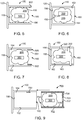
- Figure 5 illustrates a blind boss 150 within a cavity 164 wherein the cavity is threaded 400 on the internal annular wall 162.
- the threading provides an undercut wherein the anchor material maybe caught to better hold the RFID device 300 within the anchor material.
- Figure 6 illustrates aspects of a blind boss with a prong 450 extending from the closed end 155 of the blind boss and into the cavity 164.
- the prong 450 is constructed of a low or non-conductive material, to avoid interference with the RFID device.
- the prong is preferable formed with the blind boss.
- the anchor material surrounds at least part of the prong 450 thereby further anchoring the material to another point.
- the surface of the prong may be roughened to urge greater adherence.
- Figures 7 teaches an insertable end sleeve 500 which may be added to a blind boss 150 and affixed to the internal annular wall 162 partially within he cavity 164.
- the end sleeve 500 effectively reduces the diameter of the open proximal end 160 of the blind boss.
- the end sleeve is of a size and shape to mate with the internal annular wall for the blind boss.
- the end sleeve is hoop shaped with a predetermined thickness 502 and forming a hoop annular wall 504.
- the sleeve thickness may be larger and may also extend as a solid end blocking the entire opening to the blind boss.
- Figure 8 illustrates a blind boss 150 with passageways 600 fluidly communicating between the cavity and the external annular wall 163. Portions of the anchor material 202 are shown affixed within the passageways to further anchor the RFID device during mounting.
- Figure 9 illustrates an assembly view of an insertable anchored RFID device.
- a plug 700 which is at least a hollow shape having an external wall 702 corresponding to the blind boss's internal annular wall 162, at least a partial end cap 703, an open end 704, and an internal wall 705 forming a cavity 706 wherein the anchor material 200 is surrounding an RFID device 200.
- An air and humidity passage 707 may be included.
- an adhesive or cement 750 is placed on at least one of the external wall of the plug and the internal annular wall of the cavity 164. The plug is then slid into the blind body thereby affixing the RFID device therein.
- FIG 10 is an overview of a tracking system wherein a tractor 1002 and trailer 1004 with gaseous fuel tanks 100 having an RFID device 300 within a blind boss 150 being wirelessly interrogated for information via a RFID reader 1000.
- the RFID reader 1000 is in signal communication 1005 with the RFID device in the tank 100.
- the RFID reader is also in signal communication with a network 1100 wherein the information collected from the RFID device is provided to a server 1120.
- the information may be stored in a database 1150.
- the server 1120 may also parse the information and provide at least some of the information to computing devices a remote such as smart phones and computers to track the tank and vehicle location or provide notification to the vehicle owner or driver regarding the tank.
- the server uses decision and rule engines to parse data for use in tracking at least one of tracking a tank's location, a vehicle location, temperature when the tank was identified at a location, elevation when the tank was identified at a location, date when the tank was a t allocation, damage on the tank at a location and providing a subset of that data to another computing device.
- other input devices or sensors 1200 which may contemporaneously with the RFID reader 1000 interrogating the tank, collect other data such as jpeg, mpeg, geographical location, temperature, vehicle ID, visual inspection on the and optionally any other sensors or input device 1200 .
- the other input device or sensor may be integrated into the RFID writer/reader.
- the data provided to the server 1120 may be stored in a database 1350. That data or metadata may be sent to the server 1120 and collected and correlated to a specific tank or vehicle.
- other input devices or sensors including cameras and the like, 1004 may contemporaneously with the RFID reader interrogating the tank, collect other data such as jpeg, mpeg, geographical location, temperature, vehicle ID, visual inspection on the and optionally any other sensors or input device 1004 . That data or metadata may be sent to the server 1020 and collected and correlated to a specific tank.
Landscapes
- Engineering & Computer Science (AREA)
- Health & Medical Sciences (AREA)
- Toxicology (AREA)
- Physics & Mathematics (AREA)
- General Engineering & Computer Science (AREA)
- Mechanical Engineering (AREA)
- Artificial Intelligence (AREA)
- Computer Vision & Pattern Recognition (AREA)
- General Physics & Mathematics (AREA)
- Theoretical Computer Science (AREA)
- General Health & Medical Sciences (AREA)
- Electromagnetism (AREA)
- Filling Or Discharging Of Gas Storage Vessels (AREA)
Description
- This application is an International Patent Application which claims priority to
U.S. Patent Application No. 14/523,128 filed October 24, 2014 - This disclosure relates to a blind boss mounting for an insulated RFID tag connection tank.
- There is an ongoing balance between safety and weight with respect to pressurized fuel in motor vehicles traditional methods of reducing tank weight have included using plastic lined tanks wrapped in fibers within a binding matrix and having a fluid connection for fill/unfill.
Figure 1 shows a traditional composite tank structure. Such composite pressure vessels "T" is constructed by wrapping reinforcing fibers in a binding matrix forming a wrapped region "W" over a plastic liner "L". A polar boss "O" is connected to the liner and is partially in the wrappings. The boss has a fluid connection "V" to the inside pressure chamber "I.V.". Fiber materials are often formed of carbon fibers or other conductive materials. - These composite tanks weight less than metal tanks but are more susceptible to damage from cuts, gashes and the like. Tanks are also susceptible to stress related to weather, fill and unfill sequence. Such tanks should be inspected upon regular intervals. Such tanks are also expensive and susceptible to theft. Finally, such tanks have projected and actual life cycles depending on use, damage and the like.
- Cylindrical pressurized carbon fiber filament wrapped composite cylinders are a lightweight alternative to metal tanks for storing gaseous fuels. Such cylinder can withstand hoop and axial stresses applied internally of at least a quantity equal to the burst rating.
- Disclosed herein are exemplary implementations of aspects of devices, systems and methods of a pressurized-gas storage tanks wherein the tanks may be wirelessly tracked and identified. An identified tank may be "found" after theft. An identified tank which has previously been damaged may be identified as having prior damage for purposes of inspection and safety. An identified tank may be mapped to a location to arrange for inspection or to track assets. Signal communication to or from a Radio frequency identification (RFID) is a form of wireless communication that uses radio waves to identify and track objects RFID tags and like can be interfered with if the RFID tag is adjacent to or in contact with a conductive material or surface. Such a tank is for instance known from
JP 2002 181296 A - RFID tags are attached to items to be tracked. These tags an integrated circuit (IC), that is connected to an antenna. The tags in on board memory store the product's code or other identifier which can be read by a reader. An RFID reader is a device which can supply power via an antenna as well as data and commands to RFID tags. The reader and tag are in signal communications.
- RFID systems can be further broken down by the frequency band within which they operate: low frequency, high frequency, and ultra-high frequency. There are also two broad categories of RFID systems-passive and active. The LF band covers frequencies from 30 KHz to 300 KHz. Typically LF RFID systems operate at 125 KHz, although there are some that operate at 134 KHz. This frequency band provides a short read range of 10 cm. The HF band ranges from 3 to 30 MHz. Most HF RFID systems operate at 13.56 MHz with read ranges between 10 cm and 1 m. HF systems experience moderate sensitivity to interference. The UHF frequency band covers the range from 300 MHz to 3 GHz. Systems complying with the UHF Gen2 standard for RFID use the 860 to 960 MHz band. While there is some variance in frequency from region to region, UHF Gen2 RFID systems in most countries operate between 900 and 915 MHz.
- The read range of passive UHF systems can be as long as 12 m, and UHF RFID has a faster data transfer rate than LF or HF. UHF RFID is the most sensitive to interference.
- In active RFID systems, tags have their own transmitter and power source. Usually, the power source is a battery. Active tags broadcast their own signal to transmit the information stored on their microchips, and offer a range of up to 100 m.
- There are two main types of active tags: transponders and beacons. Transponders are "woken up" when they receive a radio signal from a reader, and then power on and respond by transmitting a signal back. Because transponders do not actively radiate radio waves until they receive a reader signal, they conserve battery life. Beacons are used in most real-time locatingsystems (RTLS), in order to track the precise location of an asset continuously. Unlike transponders, beacons are not powered on by the reader's signal. Instead, they emit signals at pre-set intervals. Depending on the level of locating accuracy required, beacons can be set to emit signals every few seconds, or once a day. Each beacon's signal is received by reader antennas that are positioned around the perimeter of the area being monitored, and communicates the tag's ID information and position.
- In passive RFID systems, the reader and reader antenna send a radio signal to the tag. The RFID tag then uses the transmitted signal to power on, and reflect energy back to the reader.
- Passive tags can be packaged in many different ways, depending on the specific RFID application requirements. For instance, they may be mounted on a substrate, or sandwiched between an adhesive layer and a paper label to create smart RFID labels. Passive tags may also be embedded in a variety of devices or packages to make the tag resistant to extreme temperatures or harsh chemicals.
- An RFID reader, also known as an interrogator, is a device that provides the connection between the tag data and the system software that needs the information. The reader communicates with tags that are within its field of operation, performing any number of tasks including simple continuous inventorying, filtering (searching for tags that meet certain criteria), writing (or encoding) to selected tags.
- It is appreciated by those skilled in the art that some of the circuits, components, and/or devices of the system disclosed in the present application are described as being in signal communication with each other, where signal communication refers to any type of communication and/or connection between the circuits, components, and/or devices that allows a circuit, component, and/or device to pass and/or receive signals and/or information from another circuit, component, and/or device. The communication and/or connection may be along any signal path between the circuits, components, and/or devices that allows signals and/or information to pass from one circuit, component. The signal paths may be non-physical such as free-space (in the case of electromagnetic propagation) or information paths through digital components where communication information is passed from one circuit, component, module, and/or device to another in varying analog and/or digital formats without passing through a direct electromagnetic connection. These information paths may also include analog-to-digital conversions ("ADC"), digital-to-analog ("DAC") conversions, data transformations such as, for example, fast Fourier transforms ("FFTs"), time-to-frequency conversations, frequency-to-time conversions, database mapping, signal processing steps, coding, modulations, demodulations, etc.
- In some exemplary implementations, aspects disclosed are a tracking system for conductive material pressurized composite tanks, including a composite pressurized tank vessel having a plastic, non-carbon, boss with an open proximal end and a cavity within surrounded by an annular wall with an anchor material affixed therein and, an RFID device affixed within the anchor material.
- In some exemplary implementations, aspects disclosed are a tracking system for conductive material pressurized composite tanks, including a composite pressurized tank vessel having a plastic, non-carbon, boss with an open proximal end and a cavity within surrounded by an annular wall with an RFID device within an anchor material affixed therein, an RFID device affixed within the anchor material; data stored in memory of the RFID device; an RFID reader in signal communication with the RFID device; and, whereby information stored in the memory of the RFID device is read. In some instances the data collected by the RFID reader is provided to one or more of a network and a server.
- In the above implementations the blind boss may have one or more of a roughened internal annular wall, a coating added to the internal annular wall, threading on the annular wall, a prong in its cavity.
- In the above implementations the blind boss may have one or more of an insert able end sleeve affixed to the internal annular wall partially within the cavity, and an insert able plug affixed to the internal annular wall.
- In some exemplary implementations, aspects disclosed are an asset management system for conductive pressurized composite tanks including having a composite pressurized tank vessel with a plastic, non-carbon, blind boss with an open proximal end, a cavity, surrounded by an internal annular wall, an RFID device anchor material affixed within the blind boss; and, an RFID reader in signal communications with the RFID device. In some instance the RFID reader is in signal communications with a server via a network and provides the data collected from the RFID device to the server. The collected data may be provided from the server to a remote computing device.
- In some exemplary implementations, aspects disclosed are an asset management system for conductive pressurized composite tanks including having a composite pressurized tank vessel with a plastic, non-carbon, blind boss with an open proximal end, a cavity, surrounded by an internal annular wall, an RFID device anchor material affixed within the blind boss; and, an RFID reader in signal communications with the RFID device. In some instance the RFID reader is in signal communications at about 15 meters. In some instance the RFID reader is in signal communications at about 10 meters. In some instance the RFID reader is in signal communications at about 5 meters
- In some exemplary implementations, aspects disclosed are an asset management system for conductive pressurized composite tanks including having a composite pressurized tank vessel with a plastic, non-carbon, blind boss with an open proximal end, a cavity, surrounded by an internal annular wall, an RFID device anchor material affixed within the blind boss; and, an RFID reader in signal communications with the RFID device. In some instance the RFID reader is in signal communications with a server via a network and provides the data collected from the RFID device to the server. In some instances an input devices contemporaneously with the RFID reader collect other data related to or arising from the tank, vehicle or location of the tank or vehicle including but not limited to one or more of a jpeg, mpeg, geographical location, temperature, vehicle ID, date and time, and, said input device provides said other data to the server via the network.
- In some exemplary implementations, aspects disclosed are methods of tracking composite conductive pressurized tanks, the method including affixing an RFID device in a plastic, non-conductive, blind boss, with an anchor material, on a tank; store data in the memory of the RFID device; read the data stored with an RFID writer/reader; and, providing the collected data to a server via a network. In some instances the method includes using the RFID writer/reader to write data on the RFID device.
- The above-mentioned features of the present disclosure will become more apparent with reference to the following description taken in conjunction with the accompanying drawings wherein like reference numerals denote like elements and in which:
-
FIG. 1 is a traditional composite tank; -
FIG. 2 a composite tank with a blind boss; -
FIG. 3 and 4 are close up of the blind boss inFigure 2 ; -
FIG. 5-9 are alternate configurations of blind boss structure; and, -
FIG. 10 shows an overview of a computerized tracking system. - While the specification concludes with claims defining the features of the present disclosure that are regarded as novel, it is believed that the present disclosure's teachings will be better understood from a consideration of the following description in conjunction with the appendix, figures, in which like reference numerals are carried forward. All descriptions and callouts in the Figures are hereby incorporated by this reference as if fully set forth herein.
-
Figure 1 illustrates a traditional composite pressurized gas vessel. These tanks are often used for the transport of natural gas or hydrogen fuel on vehicles to reduce weight the tanks are often composite layers and not metal. A traditional tank "T" comprises an internal volumetric space "I.V." defined by a plastic liner "L". The liner has an output neck "O" which fluidly connects the I.V. with the external world via a valve "V". The liner "L" is wrapped with material and resins "W" which form a boundary to the migration of gaseous fuels. -
Figure 2-4 illustrates aspects of compositepressurized gas tank 100 with a blind boss and tracking 105. The tank .100 is formed by aliner 120 surrounded by awrapping region 130 which comprises a matrix of fabric in a binder such as an adhesive or resin which has been cured. An interiorvolumetric space 133 is defined by the liner. The exterior of thetank 135 may be further wrapped in protective material (not shown). The wrapping region, utilizes fiber materials such as carbon fiber, KEVLAR TM fiber, glass fiber, and/or other fiber type materials in a matrix binder to form a strong, burst resistant, lightweight tank. However, carbon fiber is conductive and testing has shown it to interfere with radio frequency transmission and reception. - The
blind boss 150 disclosed herein is formed as part of the non-carbon plastic liner, or it is added to the end of a carbon plastic liner but formed of non-carbon plastic. The blind boss has a closeddistal end 155 and an openproximal end 160 and internalannular wall 162 and externalannular wall 163, aninternal cavity 164. Within the blind boss ananchor material 200 which does not interfere with communications to or from a RFID device is added along with theRFID 300 device. - RFID device contains memory which contains data. Data may be coding to identify the tank, the origin, the date of service. The RFID device may contain at least one of non-volatile memory, read only memory, writable memory. Those of ordinary skill in the art will recognize that RFID devices are writeable. Materials which do not interfere have low dielectric properties such as plastic (non-carbon) and epoxy, acrylic or silicon sealants. The anchor material should be surround at least a portion of the RFID device and adhere to the internal
annular wall 162 of thecavity 164. AnRFID reader 1000 wirelessly reads the information on the RFID tag / device which may include unique identifier numbers, manufacture information and hours of service. RFID readers may also be writers and using software such as LLRP (Low Level Reader Protocol) a UHF RFID can write to the RFID device. Geo location may also be acquired along with other relevant data and meta data such as vehicle tank is on duty on, tank manufacture, temperature, fill history, visual inspection etc. - An
RFID reader 1000 wirelessly reads the information on the RFID tag / device which may include unique identifier numbers, manufacture information and hours of service. Geo location may also be acquired along with other relevant data and meta data such as vehicle tank is on duty on, tank manufacture, temperature, fill history, visual inspection etc. - In some instance the
annular wall 162 may be roughened prior to the insertion of the anchor material to provide a rougher surface for the anchor material to adhere to. In some instances at least a portion of the annular wall may be coasted with anadditional anchor material 170. The additional material may be an insulator, a shock absorber, an adhesive or the like. - The RFID device, and in particular the antennae, is sensitive to interference. The greater the radio interference the lower the performance. Low dielectric materials generally do not reflect RF energy and thus have a lower impact on performance of n RFID device than a high dielectric material. Low dielectric materials include non-carbon plastic High dielectric materials tend to reflect more RFID energy and therefore detune a RFID.
-
Figure 5 illustrates ablind boss 150 within acavity 164 wherein the cavity is threaded 400 on the internalannular wall 162. The threading provides an undercut wherein the anchor material maybe caught to better hold theRFID device 300 within the anchor material.Figure 6 illustrates aspects of a blind boss with aprong 450 extending from theclosed end 155 of the blind boss and into thecavity 164. Theprong 450 is constructed of a low or non-conductive material, to avoid interference with the RFID device. The prong is preferable formed with the blind boss. Those of ordinary skill in the art with recognize that a single prong may be replaced with multiple prongs without departing from the scope of this disclosure. The anchor material surrounds at least part of theprong 450 thereby further anchoring the material to another point. The surface of the prong may be roughened to urge greater adherence. -
Figures 7 teaches aninsertable end sleeve 500 which may be added to ablind boss 150 and affixed to the internalannular wall 162 partially within hecavity 164. Theend sleeve 500 effectively reduces the diameter of the openproximal end 160 of the blind boss. Shown here the end sleeve is of a size and shape to mate with the internal annular wall for the blind boss. The end sleeve is hoop shaped with apredetermined thickness 502 and forming a hoopannular wall 504. Those of ordinary skill in the art will recognize that it is within the disclosure that the sleeve thickness may be larger and may also extend as a solid end blocking the entire opening to the blind boss. -
Figure 8 illustrates ablind boss 150 withpassageways 600 fluidly communicating between the cavity and the externalannular wall 163. Portions of theanchor material 202 are shown affixed within the passageways to further anchor the RFID device during mounting. -
Figure 9 illustrates an assembly view of an insertable anchored RFID device. Aplug 700 which is at least a hollow shape having anexternal wall 702 corresponding to the blind boss's internalannular wall 162, at least apartial end cap 703, anopen end 704, and aninternal wall 705 forming acavity 706 wherein theanchor material 200 is surrounding anRFID device 200. An air andhumidity passage 707 may be included. After placing the anchor material and RFID device in theplug 700, an adhesive orcement 750 is placed on at least one of the external wall of the plug and the internal annular wall of thecavity 164. The plug is then slid into the blind body thereby affixing the RFID device therein. -
Figure 10 is an overview of a tracking system wherein atractor 1002 andtrailer 1004 withgaseous fuel tanks 100 having anRFID device 300 within ablind boss 150 being wirelessly interrogated for information via aRFID reader 1000. TheRFID reader 1000 is insignal communication 1005 with the RFID device in thetank 100. The RFID reader is also in signal communication with anetwork 1100 wherein the information collected from the RFID device is provided to aserver 1120. The information may be stored in a database 1150. Theserver 1120 may also parse the information and provide at least some of the information to computing devices a remote such as smart phones and computers to track the tank and vehicle location or provide notification to the vehicle owner or driver regarding the tank. In some instances the server uses decision and rule engines to parse data for use in tracking at least one of tracking a tank's location, a vehicle location, temperature when the tank was identified at a location, elevation when the tank was identified at a location, date when the tank was a t allocation, damage on the tank at a location and providing a subset of that data to another computing device. - Additionally, other input devices or
sensors 1200 which may contemporaneously with theRFID reader 1000 interrogating the tank, collect other data such as jpeg, mpeg, geographical location, temperature, vehicle ID, visual inspection on the and optionally any other sensors orinput device 1200 . In some instances the other input device or sensor may be integrated into the RFID writer/reader. The data provided to theserver 1120 may be stored in adatabase 1350. That data or metadata may be sent to theserver 1120 and collected and correlated to a specific tank or vehicle. - Additionally, other input devices or sensors including cameras and the like, 1004 may contemporaneously with the RFID reader interrogating the tank, collect other data such as jpeg, mpeg, geographical location, temperature, vehicle ID, visual inspection on the and optionally any other sensors or
input device 1004 . That data or metadata may be sent to the server 1020 and collected and correlated to a specific tank.
Claims (15)
- A tracking system for conductive material pressurized composite tanks, the system comprising:a composite pressurized tank vessel (100) comprising;a carbon plastic liner (120) surrounded by a wrapping region (130);an interior volumetric space (133);a plastic, non-carbon, blind boss (150) with a closed distal end (155) and an open proximal end (160) wherein the blind boss (150) is added to the end of the carbon plastic liner (120);a cavity (164) in the blind boss surrounded by an annular wall (162);an anchor material (200) affixed within the cavity of the blind boss; and,an RFID device (300) affixed within the anchor material (200).
- The tracking system for conductive material pressurized composite tanks of claim 1 further comprising:data stored in memory in the RFID device (300);an RFID reader in signal communication with the RFID device (300); and,whereby data stored in the memory of the RFID device (300) is read.
- The tracking system for conductive material pressurized composite tanks of claim 1
wherein the blind boss (150) further comprises a roughened internal annular wall (162). - The tracking system for conductive material pressurized composite tanks of claim 1
wherein the blind boss (150) is threaded on its internal annular wall. - The tracking system for conductive material pressurized composite tanks of claim 1 further comprising a prong (450) in its cavity.
- The tracking system for conductive material pressurized composite tanks of claim 1 further comprising an insertable end sleeve (500) affixed to the internal annular wall partially within the cavity; and,
whereby the sleeve (500) effectively reduces the diameter of the open proximal end (160) of the blind boss (150). - The tracking system for conductive material pressurized composite tanks of claim 1 further comprising an insertable plug (700) affixed to the internal annular wall (162) partially within the cavity (164); and,
whereby the plug (700) contains the anchor material and the RFID device (300). - The tracking system for conductive material pressurized composite tanks of claim 1 further comprising a coating of additional anchor material (170) on the internal annular wall.
- The tracking system for conductive material pressurized composite tanks of claim 2
wherein the RFID reader provides the information read from the RFID device (300) to a network (1100). - The tracking system for conductive material pressurized composite tanks, of claim 2
wherein the RFID reader is in signal communications with a server (1120) via a network (1100) and provides the data collected from the RFID device (300) to the server. - The tracking system for conductive material pressurized composite tanks, of claim 10 wherein the RFID reader is in signal communications with the RFID device (300) at a distance of up to about 5 meters, or of up to about 10 metres or of about up to 15 metres.
- The tracking system for conductive material pressurized composite tanks, of claim 10 wherein the server parses the data provided and provides at least some of that data to a remote computing device (1300).
- The tracking system for conductive material pressurized composite tanks, of claim 2 further comprising: an input device (1200) which contemporaneously with the RFID reader (1000), collects other data including but not limited to one or more of a jpeg, mpeg, geographical location, temperature, vehicle ID, date and time; and, said input device provides said other data to the server via the network.
- The tracking system for conductive material pressurized composite tanks of claim 2, wherein the anchor material has a low-dielectric.
- A method of tracking composite conductive material pressurized tanks in a tracking system according to any one of Claims 1 to 14, the method comprising:adding a blind boss (150) to the end of a carbon plastic liner (120) of a composite pressurized tank,wherein the blind boss comprises an open cavity (164);affixing an RFID device (300) in the cavity with an anchor material (200);storing data in the memory of the RFID device (300);reading the data stored with an RFID writer/reader; and,providing the collected data to a server via a network.
Applications Claiming Priority (2)
| Application Number | Priority Date | Filing Date | Title |
|---|---|---|---|
| US14/523,128 US9534738B2 (en) | 2014-10-24 | 2014-10-24 | Composite pressure tank identification and tracking |
| PCT/US2015/055395 WO2016064626A1 (en) | 2014-10-24 | 2015-10-13 | Composite pressure tank identification and tracking |
Publications (3)
| Publication Number | Publication Date |
|---|---|
| EP3209926A1 EP3209926A1 (en) | 2017-08-30 |
| EP3209926A4 EP3209926A4 (en) | 2017-12-13 |
| EP3209926B1 true EP3209926B1 (en) | 2020-06-24 |
Family
ID=55761338
Family Applications (1)
| Application Number | Title | Priority Date | Filing Date |
|---|---|---|---|
| EP15853008.9A Active EP3209926B1 (en) | 2014-10-24 | 2015-10-13 | Composite pressure tank identification and tracking |
Country Status (6)
| Country | Link |
|---|---|
| US (2) | US9534738B2 (en) |
| EP (1) | EP3209926B1 (en) |
| JP (1) | JP6467058B2 (en) |
| CN (1) | CN107636379B (en) |
| CA (1) | CA2965656C (en) |
| WO (1) | WO2016064626A1 (en) |
Families Citing this family (8)
| Publication number | Priority date | Publication date | Assignee | Title |
|---|---|---|---|---|
| US9534738B2 (en) * | 2014-10-24 | 2017-01-03 | Quantum Fuel Systems Llc | Composite pressure tank identification and tracking |
| US10018303B1 (en) * | 2017-02-13 | 2018-07-10 | Compass Natural Gas Partners, LP | Method and system for transfer of natural gas |
| DE102018128364A1 (en) * | 2018-11-13 | 2020-05-14 | Bayerische Motoren Werke Aktiengesellschaft | System and method for identifying a pressure vessel and pressure vessel |
| DE102019108381A1 (en) * | 2019-04-01 | 2020-10-01 | Bayerische Motoren Werke Aktiengesellschaft | Pressure vessel, motor vehicle and process |
| DE102020001077A1 (en) * | 2020-02-19 | 2021-08-19 | Bauer Kompressoren Gmbh | Analysis device for gases in a pressurized gas storage tank |
| WO2022002331A1 (en) | 2020-06-30 | 2022-01-06 | Everfuel Europe A/S | A hydrogen supervisory control and data acquisition system |
| JP7801861B2 (en) * | 2021-08-05 | 2026-01-19 | エア・ウォーター株式会社 | cylinder |
| CN119267790A (en) * | 2024-11-25 | 2025-01-07 | 清华大学 | Gas storage cylinder and monitoring method and management system thereof |
Family Cites Families (25)
| Publication number | Priority date | Publication date | Assignee | Title |
|---|---|---|---|---|
| DE69530126T2 (en) * | 1995-12-04 | 2003-12-11 | Toray Industries | PRESSURE TANKS AND METHOD FOR THE PRODUCTION THEREOF |
| EP1156266A3 (en) * | 2000-05-15 | 2005-11-23 | mcs cylinder systems GmbH | Support fot identification data and said data for a composite pressure vessel |
| JP2002181296A (en) | 2000-12-12 | 2002-06-26 | Hanex Co Ltd | Mounting structure of rfid tag and mounting method of rfid tag |
| KR100469636B1 (en) * | 2004-03-11 | 2005-02-02 | 주식회사 케이시알 | The high gas-tighten metallic nozzle-boss for the high pressure composite vessel |
| WO2006075309A2 (en) * | 2005-01-13 | 2006-07-20 | Idtek Track-And-Trace S.A. | Device for interrogating transponders |
| US7768409B2 (en) * | 2005-06-10 | 2010-08-03 | American Air Liquide, Inc. | Embedded RFID scanner for mobile product management |
| EP1928746A2 (en) * | 2005-08-22 | 2008-06-11 | Advanced Technology Materials, Inc. | Material containment system |
| JP5106932B2 (en) * | 2007-06-28 | 2012-12-26 | 日本エア・リキード株式会社 | Fluid supply system |
| US7633206B2 (en) * | 2007-07-26 | 2009-12-15 | Delaware Capital Formation, Inc. | Reflective and slanted array channelized sensor arrays |
| JP2009103213A (en) | 2007-10-23 | 2009-05-14 | Koatsu Gas Kogyo Co Ltd | Wireless IC tag for gas cylinder |
| CN101458773A (en) * | 2007-12-14 | 2009-06-17 | 台湾铭板股份有限公司 | Pressure container device combined with induction type identification technology |
| US8040244B2 (en) * | 2008-11-07 | 2011-10-18 | International Business Machines Corporation | Closure with passive electronic sensor for tamper detection and related method |
| KR101056997B1 (en) | 2008-12-24 | 2011-08-16 | (주) 에코센스 | Location tracking device between chemicals using RFID, GPS, wireless communication |
| JP5511215B2 (en) | 2009-04-07 | 2014-06-04 | 三菱電機株式会社 | RFID tag for gas cylinder |
| US8517206B2 (en) * | 2009-05-19 | 2013-08-27 | Quantum Fuel Systems Technologies Worldwide Inc. | High pressure storage vessel |
| US9281415B2 (en) * | 2010-09-10 | 2016-03-08 | The Board Of Trustees Of The Leland Stanford Junior University | Pressure sensing apparatuses and methods |
| JP2012077780A (en) | 2010-09-30 | 2012-04-19 | Taiyo Nippon Sanso Corp | Gas cylinder |
| ES2671716T3 (en) * | 2010-11-29 | 2018-06-08 | Air Products And Chemicals, Inc. | Method and apparatus for measuring the true content of a gas cylinder under pressure |
| US9022080B2 (en) * | 2012-02-08 | 2015-05-05 | Honda Motor Co., Ltd. | Communication device activated by fuel door |
| CN202580602U (en) * | 2012-05-22 | 2012-12-05 | 四川鼎天电子标识技术系统有限公司 | Safe gas filling management system for compressed natural gas (CNG) automobile |
| US9212785B2 (en) * | 2012-10-11 | 2015-12-15 | Varian Semiconductor Equipment Associates, Inc. | Passive isolation assembly and gas transport system |
| KR101517552B1 (en) * | 2013-08-22 | 2015-05-04 | 한국생산기술연구원 | Pressure vessel history management apparatus and its using method |
| US9712761B2 (en) * | 2014-05-28 | 2017-07-18 | Qualcomm Incorporated | Method for embedding product information in video using radio frequencey information |
| US9534738B2 (en) * | 2014-10-24 | 2017-01-03 | Quantum Fuel Systems Llc | Composite pressure tank identification and tracking |
| US10408383B2 (en) * | 2015-10-30 | 2019-09-10 | Carleton Technologies, Inc. | Boss and seal for a high-pressure vessel |
-
2014
- 2014-10-24 US US14/523,128 patent/US9534738B2/en active Active
-
2015
- 2015-10-13 CN CN201580070601.2A patent/CN107636379B/en active Active
- 2015-10-13 JP JP2017540964A patent/JP6467058B2/en active Active
- 2015-10-13 WO PCT/US2015/055395 patent/WO2016064626A1/en not_active Ceased
- 2015-10-13 CA CA2965656A patent/CA2965656C/en active Active
- 2015-10-13 EP EP15853008.9A patent/EP3209926B1/en active Active
-
2016
- 2016-11-18 US US15/356,198 patent/US10181064B2/en active Active
Non-Patent Citations (1)
| Title |
|---|
| None * |
Also Published As
| Publication number | Publication date |
|---|---|
| WO2016064626A1 (en) | 2016-04-28 |
| EP3209926A4 (en) | 2017-12-13 |
| US9534738B2 (en) | 2017-01-03 |
| US10181064B2 (en) | 2019-01-15 |
| CA2965656C (en) | 2018-03-20 |
| CN107636379B (en) | 2020-06-19 |
| US20160116115A1 (en) | 2016-04-28 |
| JP2017533394A (en) | 2017-11-09 |
| JP6467058B2 (en) | 2019-02-06 |
| CA2965656A1 (en) | 2016-04-28 |
| CN107636379A (en) | 2018-01-26 |
| EP3209926A1 (en) | 2017-08-30 |
| US20180032769A1 (en) | 2018-02-01 |
Similar Documents
| Publication | Publication Date | Title |
|---|---|---|
| US10181064B2 (en) | Composite pressure tank identification and tracking | |
| US11842244B2 (en) | Non-transferable radio frequency identification label or tag | |
| US9122967B2 (en) | Radio frequency identification tags and methods employing ceramic components, which may be suitable for use in extreme environmental conditions | |
| EP3393662B1 (en) | Rfid system for identification of cryogenic straws | |
| US20080136619A1 (en) | Systems and methods for incorporating an rfid circuit into a sensor device | |
| AU2011265835B2 (en) | A transponder, RFID system and methods of operation | |
| CN101145192B (en) | Smart radio-frequency identification infrastructure and method | |
| US8952790B2 (en) | Strong passive ad-hoc radio-frequency identification | |
| US11347991B1 (en) | Identification devices | |
| JP2017533394A5 (en) | ||
| GB2480611A (en) | Use of a tag with an underwater installation | |
| US9367786B2 (en) | Radio with embedded RFID | |
| CN105184354B (en) | Broadband RFID electronic tag | |
| KR20100096532A (en) | Container with electronic tag and its manufacturing method | |
| KR101365610B1 (en) | Book comprising near field communication device and protective layer for protecting the same | |
| KR200434463Y1 (en) | RDF adapter package block and RDF tag using the same | |
| KR101415485B1 (en) | Clamp Type RFID Device For Metal Tool | |
| Alessenko et al. | DEVELOPMENT OF A RADIO FREQUENCY IDENTIFICATION SYSTEM OF RECLOSERS | |
| KR20100087957A (en) | Apparatus of isolating the electro magnetic wave used in radio frequency identification system and method of the same |
Legal Events
| Date | Code | Title | Description |
|---|---|---|---|
| STAA | Information on the status of an ep patent application or granted ep patent |
Free format text: STATUS: THE INTERNATIONAL PUBLICATION HAS BEEN MADE |
|
| PUAI | Public reference made under article 153(3) epc to a published international application that has entered the european phase |
Free format text: ORIGINAL CODE: 0009012 |
|
| STAA | Information on the status of an ep patent application or granted ep patent |
Free format text: STATUS: REQUEST FOR EXAMINATION WAS MADE |
|
| 17P | Request for examination filed |
Effective date: 20170524 |
|
| AK | Designated contracting states |
Kind code of ref document: A1 Designated state(s): AL AT BE BG CH CY CZ DE DK EE ES FI FR GB GR HR HU IE IS IT LI LT LU LV MC MK MT NL NO PL PT RO RS SE SI SK SM TR |
|
| AX | Request for extension of the european patent |
Extension state: BA ME |
|
| A4 | Supplementary search report drawn up and despatched |
Effective date: 20171109 |
|
| RIC1 | Information provided on ipc code assigned before grant |
Ipc: F17C 13/02 20060101AFI20171103BHEP Ipc: G06K 17/00 20060101ALI20171103BHEP |
|
| DAV | Request for validation of the european patent (deleted) | ||
| DAX | Request for extension of the european patent (deleted) | ||
| GRAP | Despatch of communication of intention to grant a patent |
Free format text: ORIGINAL CODE: EPIDOSNIGR1 |
|
| STAA | Information on the status of an ep patent application or granted ep patent |
Free format text: STATUS: GRANT OF PATENT IS INTENDED |
|
| INTG | Intention to grant announced |
Effective date: 20191023 |
|
| GRAJ | Information related to disapproval of communication of intention to grant by the applicant or resumption of examination proceedings by the epo deleted |
Free format text: ORIGINAL CODE: EPIDOSDIGR1 |
|
| STAA | Information on the status of an ep patent application or granted ep patent |
Free format text: STATUS: REQUEST FOR EXAMINATION WAS MADE |
|
| INTC | Intention to grant announced (deleted) | ||
| GRAR | Information related to intention to grant a patent recorded |
Free format text: ORIGINAL CODE: EPIDOSNIGR71 |
|
| GRAS | Grant fee paid |
Free format text: ORIGINAL CODE: EPIDOSNIGR3 |
|
| STAA | Information on the status of an ep patent application or granted ep patent |
Free format text: STATUS: GRANT OF PATENT IS INTENDED |
|
| GRAA | (expected) grant |
Free format text: ORIGINAL CODE: 0009210 |
|
| STAA | Information on the status of an ep patent application or granted ep patent |
Free format text: STATUS: THE PATENT HAS BEEN GRANTED |
|
| AK | Designated contracting states |
Kind code of ref document: B1 Designated state(s): AL AT BE BG CH CY CZ DE DK EE ES FI FR GB GR HR HU IE IS IT LI LT LU LV MC MK MT NL NO PL PT RO RS SE SI SK SM TR |
|
| INTG | Intention to grant announced |
Effective date: 20200520 |
|
| REG | Reference to a national code |
Ref country code: GB Ref legal event code: FG4D |
|
| REG | Reference to a national code |
Ref country code: CH Ref legal event code: EP |
|
| REG | Reference to a national code |
Ref country code: AT Ref legal event code: REF Ref document number: 1284245 Country of ref document: AT Kind code of ref document: T Effective date: 20200715 |
|
| REG | Reference to a national code |
Ref country code: DE Ref legal event code: R096 Ref document number: 602015054857 Country of ref document: DE |
|
| REG | Reference to a national code |
Ref country code: IE Ref legal event code: FG4D |
|
| PG25 | Lapsed in a contracting state [announced via postgrant information from national office to epo] |
Ref country code: NO Free format text: LAPSE BECAUSE OF FAILURE TO SUBMIT A TRANSLATION OF THE DESCRIPTION OR TO PAY THE FEE WITHIN THE PRESCRIBED TIME-LIMIT Effective date: 20200924 Ref country code: FI Free format text: LAPSE BECAUSE OF FAILURE TO SUBMIT A TRANSLATION OF THE DESCRIPTION OR TO PAY THE FEE WITHIN THE PRESCRIBED TIME-LIMIT Effective date: 20200624 Ref country code: LT Free format text: LAPSE BECAUSE OF FAILURE TO SUBMIT A TRANSLATION OF THE DESCRIPTION OR TO PAY THE FEE WITHIN THE PRESCRIBED TIME-LIMIT Effective date: 20200624 Ref country code: SE Free format text: LAPSE BECAUSE OF FAILURE TO SUBMIT A TRANSLATION OF THE DESCRIPTION OR TO PAY THE FEE WITHIN THE PRESCRIBED TIME-LIMIT Effective date: 20200624 Ref country code: GR Free format text: LAPSE BECAUSE OF FAILURE TO SUBMIT A TRANSLATION OF THE DESCRIPTION OR TO PAY THE FEE WITHIN THE PRESCRIBED TIME-LIMIT Effective date: 20200925 |
|
| REG | Reference to a national code |
Ref country code: LT Ref legal event code: MG4D |
|
| PG25 | Lapsed in a contracting state [announced via postgrant information from national office to epo] |
Ref country code: RS Free format text: LAPSE BECAUSE OF FAILURE TO SUBMIT A TRANSLATION OF THE DESCRIPTION OR TO PAY THE FEE WITHIN THE PRESCRIBED TIME-LIMIT Effective date: 20200624 Ref country code: LV Free format text: LAPSE BECAUSE OF FAILURE TO SUBMIT A TRANSLATION OF THE DESCRIPTION OR TO PAY THE FEE WITHIN THE PRESCRIBED TIME-LIMIT Effective date: 20200624 Ref country code: HR Free format text: LAPSE BECAUSE OF FAILURE TO SUBMIT A TRANSLATION OF THE DESCRIPTION OR TO PAY THE FEE WITHIN THE PRESCRIBED TIME-LIMIT Effective date: 20200624 Ref country code: BG Free format text: LAPSE BECAUSE OF FAILURE TO SUBMIT A TRANSLATION OF THE DESCRIPTION OR TO PAY THE FEE WITHIN THE PRESCRIBED TIME-LIMIT Effective date: 20200924 |
|
| REG | Reference to a national code |
Ref country code: NL Ref legal event code: MP Effective date: 20200624 |
|
| REG | Reference to a national code |
Ref country code: AT Ref legal event code: MK05 Ref document number: 1284245 Country of ref document: AT Kind code of ref document: T Effective date: 20200624 |
|
| PG25 | Lapsed in a contracting state [announced via postgrant information from national office to epo] |
Ref country code: NL Free format text: LAPSE BECAUSE OF FAILURE TO SUBMIT A TRANSLATION OF THE DESCRIPTION OR TO PAY THE FEE WITHIN THE PRESCRIBED TIME-LIMIT Effective date: 20200624 Ref country code: AL Free format text: LAPSE BECAUSE OF FAILURE TO SUBMIT A TRANSLATION OF THE DESCRIPTION OR TO PAY THE FEE WITHIN THE PRESCRIBED TIME-LIMIT Effective date: 20200624 |
|
| PG25 | Lapsed in a contracting state [announced via postgrant information from national office to epo] |
Ref country code: PT Free format text: LAPSE BECAUSE OF FAILURE TO SUBMIT A TRANSLATION OF THE DESCRIPTION OR TO PAY THE FEE WITHIN THE PRESCRIBED TIME-LIMIT Effective date: 20201026 Ref country code: ES Free format text: LAPSE BECAUSE OF FAILURE TO SUBMIT A TRANSLATION OF THE DESCRIPTION OR TO PAY THE FEE WITHIN THE PRESCRIBED TIME-LIMIT Effective date: 20200624 Ref country code: SM Free format text: LAPSE BECAUSE OF FAILURE TO SUBMIT A TRANSLATION OF THE DESCRIPTION OR TO PAY THE FEE WITHIN THE PRESCRIBED TIME-LIMIT Effective date: 20200624 Ref country code: EE Free format text: LAPSE BECAUSE OF FAILURE TO SUBMIT A TRANSLATION OF THE DESCRIPTION OR TO PAY THE FEE WITHIN THE PRESCRIBED TIME-LIMIT Effective date: 20200624 Ref country code: AT Free format text: LAPSE BECAUSE OF FAILURE TO SUBMIT A TRANSLATION OF THE DESCRIPTION OR TO PAY THE FEE WITHIN THE PRESCRIBED TIME-LIMIT Effective date: 20200624 Ref country code: CZ Free format text: LAPSE BECAUSE OF FAILURE TO SUBMIT A TRANSLATION OF THE DESCRIPTION OR TO PAY THE FEE WITHIN THE PRESCRIBED TIME-LIMIT Effective date: 20200624 Ref country code: RO Free format text: LAPSE BECAUSE OF FAILURE TO SUBMIT A TRANSLATION OF THE DESCRIPTION OR TO PAY THE FEE WITHIN THE PRESCRIBED TIME-LIMIT Effective date: 20200624 Ref country code: IT Free format text: LAPSE BECAUSE OF FAILURE TO SUBMIT A TRANSLATION OF THE DESCRIPTION OR TO PAY THE FEE WITHIN THE PRESCRIBED TIME-LIMIT Effective date: 20200624 |
|
| PG25 | Lapsed in a contracting state [announced via postgrant information from national office to epo] |
Ref country code: PL Free format text: LAPSE BECAUSE OF FAILURE TO SUBMIT A TRANSLATION OF THE DESCRIPTION OR TO PAY THE FEE WITHIN THE PRESCRIBED TIME-LIMIT Effective date: 20200624 Ref country code: SK Free format text: LAPSE BECAUSE OF FAILURE TO SUBMIT A TRANSLATION OF THE DESCRIPTION OR TO PAY THE FEE WITHIN THE PRESCRIBED TIME-LIMIT Effective date: 20200624 Ref country code: IS Free format text: LAPSE BECAUSE OF FAILURE TO SUBMIT A TRANSLATION OF THE DESCRIPTION OR TO PAY THE FEE WITHIN THE PRESCRIBED TIME-LIMIT Effective date: 20201024 |
|
| REG | Reference to a national code |
Ref country code: DE Ref legal event code: R097 Ref document number: 602015054857 Country of ref document: DE |
|
| PG25 | Lapsed in a contracting state [announced via postgrant information from national office to epo] |
Ref country code: DK Free format text: LAPSE BECAUSE OF FAILURE TO SUBMIT A TRANSLATION OF THE DESCRIPTION OR TO PAY THE FEE WITHIN THE PRESCRIBED TIME-LIMIT Effective date: 20200624 |
|
| PLBE | No opposition filed within time limit |
Free format text: ORIGINAL CODE: 0009261 |
|
| STAA | Information on the status of an ep patent application or granted ep patent |
Free format text: STATUS: NO OPPOSITION FILED WITHIN TIME LIMIT |
|
| REG | Reference to a national code |
Ref country code: CH Ref legal event code: PL |
|
| 26N | No opposition filed |
Effective date: 20210325 |
|
| PG25 | Lapsed in a contracting state [announced via postgrant information from national office to epo] |
Ref country code: MC Free format text: LAPSE BECAUSE OF FAILURE TO SUBMIT A TRANSLATION OF THE DESCRIPTION OR TO PAY THE FEE WITHIN THE PRESCRIBED TIME-LIMIT Effective date: 20200624 Ref country code: LU Free format text: LAPSE BECAUSE OF NON-PAYMENT OF DUE FEES Effective date: 20201013 |
|
| REG | Reference to a national code |
Ref country code: BE Ref legal event code: MM Effective date: 20201031 |
|
| PG25 | Lapsed in a contracting state [announced via postgrant information from national office to epo] |
Ref country code: FR Free format text: LAPSE BECAUSE OF NON-PAYMENT OF DUE FEES Effective date: 20201031 |
|
| PG25 | Lapsed in a contracting state [announced via postgrant information from national office to epo] |
Ref country code: SI Free format text: LAPSE BECAUSE OF FAILURE TO SUBMIT A TRANSLATION OF THE DESCRIPTION OR TO PAY THE FEE WITHIN THE PRESCRIBED TIME-LIMIT Effective date: 20200624 Ref country code: LI Free format text: LAPSE BECAUSE OF NON-PAYMENT OF DUE FEES Effective date: 20201031 Ref country code: CH Free format text: LAPSE BECAUSE OF NON-PAYMENT OF DUE FEES Effective date: 20201031 Ref country code: BE Free format text: LAPSE BECAUSE OF NON-PAYMENT OF DUE FEES Effective date: 20201031 |
|
| PG25 | Lapsed in a contracting state [announced via postgrant information from national office to epo] |
Ref country code: IE Free format text: LAPSE BECAUSE OF NON-PAYMENT OF DUE FEES Effective date: 20201013 |
|
| PG25 | Lapsed in a contracting state [announced via postgrant information from national office to epo] |
Ref country code: TR Free format text: LAPSE BECAUSE OF FAILURE TO SUBMIT A TRANSLATION OF THE DESCRIPTION OR TO PAY THE FEE WITHIN THE PRESCRIBED TIME-LIMIT Effective date: 20200624 Ref country code: MT Free format text: LAPSE BECAUSE OF FAILURE TO SUBMIT A TRANSLATION OF THE DESCRIPTION OR TO PAY THE FEE WITHIN THE PRESCRIBED TIME-LIMIT Effective date: 20200624 Ref country code: CY Free format text: LAPSE BECAUSE OF FAILURE TO SUBMIT A TRANSLATION OF THE DESCRIPTION OR TO PAY THE FEE WITHIN THE PRESCRIBED TIME-LIMIT Effective date: 20200624 |
|
| PG25 | Lapsed in a contracting state [announced via postgrant information from national office to epo] |
Ref country code: MK Free format text: LAPSE BECAUSE OF FAILURE TO SUBMIT A TRANSLATION OF THE DESCRIPTION OR TO PAY THE FEE WITHIN THE PRESCRIBED TIME-LIMIT Effective date: 20200624 |
|
| PGFP | Annual fee paid to national office [announced via postgrant information from national office to epo] |
Ref country code: DE Payment date: 20251029 Year of fee payment: 11 |
|
| PGFP | Annual fee paid to national office [announced via postgrant information from national office to epo] |
Ref country code: GB Payment date: 20251027 Year of fee payment: 11 |