EP3209859B1 - Wegzeitzielfunktion für vollwellenforminversion - Google Patents
Wegzeitzielfunktion für vollwellenforminversion Download PDFInfo
- Publication number
- EP3209859B1 EP3209859B1 EP15852925.5A EP15852925A EP3209859B1 EP 3209859 B1 EP3209859 B1 EP 3209859B1 EP 15852925 A EP15852925 A EP 15852925A EP 3209859 B1 EP3209859 B1 EP 3209859B1
- Authority
- EP
- European Patent Office
- Prior art keywords
- data
- seismic
- model
- error
- time shift
- Prior art date
- Legal status (The legal status is an assumption and is not a legal conclusion. Google has not performed a legal analysis and makes no representation as to the accuracy of the status listed.)
- Active
Links
- 238000000034 method Methods 0.000 claims description 72
- 230000006870 function Effects 0.000 claims description 34
- 238000012545 processing Methods 0.000 claims description 27
- 230000015654 memory Effects 0.000 claims description 6
- 230000015572 biosynthetic process Effects 0.000 description 37
- 238000005755 formation reaction Methods 0.000 description 37
- 238000005553 drilling Methods 0.000 description 30
- 239000012530 fluid Substances 0.000 description 16
- 238000004519 manufacturing process Methods 0.000 description 16
- 238000005259 measurement Methods 0.000 description 15
- 230000008569 process Effects 0.000 description 15
- 230000003068 static effect Effects 0.000 description 9
- 238000004891 communication Methods 0.000 description 8
- 238000004458 analytical method Methods 0.000 description 7
- 239000000203 mixture Substances 0.000 description 5
- 230000004044 response Effects 0.000 description 5
- XLYOFNOQVPJJNP-UHFFFAOYSA-N water Substances O XLYOFNOQVPJJNP-UHFFFAOYSA-N 0.000 description 5
- 238000005516 engineering process Methods 0.000 description 3
- 238000012986 modification Methods 0.000 description 3
- 230000004048 modification Effects 0.000 description 3
- 238000012360 testing method Methods 0.000 description 3
- 241000191291 Abies alba Species 0.000 description 2
- BVKZGUZCCUSVTD-UHFFFAOYSA-L Carbonate Chemical compound [O-]C([O-])=O BVKZGUZCCUSVTD-UHFFFAOYSA-L 0.000 description 2
- 230000008901 benefit Effects 0.000 description 2
- 230000007423 decrease Effects 0.000 description 2
- 230000007246 mechanism Effects 0.000 description 2
- 230000003287 optical effect Effects 0.000 description 2
- 230000035699 permeability Effects 0.000 description 2
- 238000011084 recovery Methods 0.000 description 2
- 230000009471 action Effects 0.000 description 1
- 230000000570 adjustive effect Effects 0.000 description 1
- 238000013459 approach Methods 0.000 description 1
- 230000005540 biological transmission Effects 0.000 description 1
- 230000008859 change Effects 0.000 description 1
- 238000006243 chemical reaction Methods 0.000 description 1
- 230000000295 complement effect Effects 0.000 description 1
- 238000007796 conventional method Methods 0.000 description 1
- 238000013480 data collection Methods 0.000 description 1
- 230000007812 deficiency Effects 0.000 description 1
- 230000001066 destructive effect Effects 0.000 description 1
- 238000011161 development Methods 0.000 description 1
- 238000007598 dipping method Methods 0.000 description 1
- 230000000694 effects Effects 0.000 description 1
- 238000011156 evaluation Methods 0.000 description 1
- 239000002360 explosive Substances 0.000 description 1
- 238000001914 filtration Methods 0.000 description 1
- 238000009472 formulation Methods 0.000 description 1
- 229930195733 hydrocarbon Natural products 0.000 description 1
- 150000002430 hydrocarbons Chemical class 0.000 description 1
- 238000003384 imaging method Methods 0.000 description 1
- 230000010365 information processing Effects 0.000 description 1
- 238000002347 injection Methods 0.000 description 1
- 239000007924 injection Substances 0.000 description 1
- 238000012804 iterative process Methods 0.000 description 1
- 238000013508 migration Methods 0.000 description 1
- 230000005012 migration Effects 0.000 description 1
- 238000012544 monitoring process Methods 0.000 description 1
- 230000000704 physical effect Effects 0.000 description 1
- 239000011148 porous material Substances 0.000 description 1
- 238000003672 processing method Methods 0.000 description 1
- 230000000644 propagated effect Effects 0.000 description 1
- 238000004549 pulsed laser deposition Methods 0.000 description 1
- 230000002285 radioactive effect Effects 0.000 description 1
- 230000009467 reduction Effects 0.000 description 1
- 238000007670 refining Methods 0.000 description 1
- 239000004576 sand Substances 0.000 description 1
- 239000004065 semiconductor Substances 0.000 description 1
- 238000012795 verification Methods 0.000 description 1
Images


Classifications
-
- G—PHYSICS
- G01—MEASURING; TESTING
- G01V—GEOPHYSICS; GRAVITATIONAL MEASUREMENTS; DETECTING MASSES OR OBJECTS; TAGS
- G01V1/00—Seismology; Seismic or acoustic prospecting or detecting
- G01V1/28—Processing seismic data, e.g. for interpretation or for event detection
- G01V1/30—Analysis
- G01V1/303—Analysis for determining velocity profiles or travel times
- G01V1/305—Travel times
-
- E—FIXED CONSTRUCTIONS
- E21—EARTH OR ROCK DRILLING; MINING
- E21B—EARTH OR ROCK DRILLING; OBTAINING OIL, GAS, WATER, SOLUBLE OR MELTABLE MATERIALS OR A SLURRY OF MINERALS FROM WELLS
- E21B43/00—Methods or apparatus for obtaining oil, gas, water, soluble or meltable materials or a slurry of minerals from wells
- E21B43/30—Specific pattern of wells, e.g. optimising the spacing of wells
-
- E—FIXED CONSTRUCTIONS
- E21—EARTH OR ROCK DRILLING; MINING
- E21B—EARTH OR ROCK DRILLING; OBTAINING OIL, GAS, WATER, SOLUBLE OR MELTABLE MATERIALS OR A SLURRY OF MINERALS FROM WELLS
- E21B47/00—Survey of boreholes or wells
- E21B47/26—Storing data down-hole, e.g. in a memory or on a record carrier
-
- E—FIXED CONSTRUCTIONS
- E21—EARTH OR ROCK DRILLING; MINING
- E21B—EARTH OR ROCK DRILLING; OBTAINING OIL, GAS, WATER, SOLUBLE OR MELTABLE MATERIALS OR A SLURRY OF MINERALS FROM WELLS
- E21B49/00—Testing the nature of borehole walls; Formation testing; Methods or apparatus for obtaining samples of soil or well fluids, specially adapted to earth drilling or wells
- E21B49/02—Testing the nature of borehole walls; Formation testing; Methods or apparatus for obtaining samples of soil or well fluids, specially adapted to earth drilling or wells by mechanically taking samples of the soil
-
- G—PHYSICS
- G01—MEASURING; TESTING
- G01V—GEOPHYSICS; GRAVITATIONAL MEASUREMENTS; DETECTING MASSES OR OBJECTS; TAGS
- G01V1/00—Seismology; Seismic or acoustic prospecting or detecting
- G01V1/28—Processing seismic data, e.g. for interpretation or for event detection
- G01V1/282—Application of seismic models, synthetic seismograms
-
- G—PHYSICS
- G01—MEASURING; TESTING
- G01V—GEOPHYSICS; GRAVITATIONAL MEASUREMENTS; DETECTING MASSES OR OBJECTS; TAGS
- G01V2210/00—Details of seismic processing or analysis
- G01V2210/60—Analysis
- G01V2210/61—Analysis by combining or comparing a seismic data set with other data
- G01V2210/614—Synthetically generated data
-
- G—PHYSICS
- G01—MEASURING; TESTING
- G01V—GEOPHYSICS; GRAVITATIONAL MEASUREMENTS; DETECTING MASSES OR OBJECTS; TAGS
- G01V2210/00—Details of seismic processing or analysis
- G01V2210/60—Analysis
- G01V2210/62—Physical property of subsurface
- G01V2210/622—Velocity, density or impedance
- G01V2210/6222—Velocity; travel time
Definitions
- waveform inversion may be employed to determine a seismic model of a subterranean formation based on the characteristics of the seismic signals.
- One type of inversion is Full Waveform Inversion (FWI), which is based on full wave propagation.
- FWI may be used for refining detailed seismic velocity fields, which may then benefit migration techniques to achieve enhanced subsurface images.
- the misfit function generally measures the difference between the recorded seismic data and the simulated waveforms, such that the full waveform (primary, multiples, converted wave etc.) of acquired seismic data may be explained by the inverted subsurface earth models.
- FWI misfit analysis may employ a mean-square difference between the observed/acquired data and simulated/calculated data. However, it may be challenging to find the minimum misfit, because one or more local minima may be present, which may not correspond to the global minimum. This may make adjusting the model to address the differences between the data challenging. Further, misfit analysis may be complicated by cycle-skipping between the predicted and observed data. One reason for such cycle-skipping is the observed data may lack low-frequency information because of physical realities in data acquisition and noise in the recorded seismic signal. To address this challenge, the quality of the starting or initial model in the vicinity of global minimum may be relevant. In another words, the background model or the low wave-number components of the model may need to be sufficiently accurate, a priori, in order to start FWI.
- the present invention resides in a computer-implemented method for seismic processing to generate a seismic image of a subterranean area as defined in claim 1.
- a preferred embodiment is defined in claim 2.
- the present invention further resides in a computing system as defined in claim 3 and in a non-transitory, computer-readable medium as defined in claim 4.
- the computing systems and methods disclosed herein are more effective methods for processing collected data that may, for example, correspond to a subsurface region. These computing systems and methods increase data processing effectiveness, efficiency, and accuracy. Such methods and computing systems may complement or replace conventional methods for processing collected data.
- This summary is provided to introduce a selection of concepts that are further described below in the detailed description. This summary is not intended to identify key or essential features of the claimed subject matter, nor is it intended to be used as an aid in limiting the scope of the claimed subject matter.
- first, second, etc. may be used herein to describe various elements, these elements should not be limited by these terms. These terms are only used to distinguish one element from another.
- a first object or step could be termed a second object or step, and, similarly, a second object or step could be termed a first object or step, without departing from the scope of the invention.
- the first object or step, and the second object or step are both, objects or steps, respectively, but they are not to be considered the same object or step.
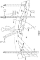
- FIGS 1A-1D illustrate simplified, schematic views of oilfield 100 having subterranean formation 102 containing reservoir 104 therein in accordance with implementations of various technologies and techniques described herein.
- Figure 1A illustrates a survey operation being performed by a survey tool, such as seismic truck 106.1, to measure properties of the subterranean formation.
- the survey operation is a seismic survey operation for producing sound vibrations.
- one such sound vibration e.g., sound vibration 112 generated by source 110
- sensors such as geophone-receivers 118, situated on the earth's surface.
- the data received 120 is provided as input data to a computer 122.1 of a seismic truck 106.1, and responsive to the input data, computer 122.1 generates seismic data output 124.
- This seismic data output may be stored, transmitted or further processed as desired, for example, by data reduction.
- Figure 1B illustrates a drilling operation being performed by drilling tools 106.2 suspended by rig 128 and advanced into subterranean formations 102 to form wellbore 136.
- Mud pit 130 is used to draw drilling mud into the drilling tools via flow line 132 for circulating drilling mud down through the drilling tools, then up wellbore 136 and back to the surface.
- the drilling mud is typically filtered and returned to the mud pit.
- a circulating system may be used for storing, controlling, or filtering the flowing drilling mud.
- the drilling tools are advanced into subterranean formations 102 to reach reservoir 104. Each well may target one or more reservoirs.
- the drilling tools are adapted for measuring downhole properties using logging while drilling tools.
- the logging while drilling tools may also be adapted for taking core sample 133 as shown.
- Computer facilities may be positioned at various locations about the oilfield 100 (e.g., the surface unit 134) and/or at remote locations.
- Surface unit 134 may be used to communicate with the drilling tools and/or offsite operations, as well as with other surface or downhole sensors.
- Surface unit 134 is capable of communicating with the drilling tools to send commands to the drilling tools, and to receive data therefrom.
- Surface unit 134 may also collect data generated during the drilling operation and produce data output 135, which may then be stored or transmitted.
- Sensors (S), such as gauges, may be positioned about oilfield 100 to collect data relating to various oilfield operations as described previously. As shown, sensor (S) is positioned in one or more locations in the drilling tools and/or at rig 128 to measure drilling parameters, such as weight on bit, torque on bit, pressures, temperatures, flow rates, compositions, rotary speed, and/or other parameters of the field operation. Sensors (S) may also be positioned in one or more locations in the circulating system.
- Drilling tools 106.2 may include a bottom hole assembly (BHA) (not shown), generally referenced, near the drill bit (e.g., within several drill collar lengths from the drill bit).
- BHA bottom hole assembly
- the bottom hole assembly includes capabilities for measuring, processing, and storing information, as well as communicating with surface unit 134.
- the bottom hole assembly further includes drill collars for performing various other measurement functions.
- the bottom hole assembly may include a communication subassembly that communicates with surface unit 134.
- the communication subassembly is adapted to send signals to and receive signals from the surface using a communications channel such as mud pulse telemetry, electro-magnetic telemetry, or wired drill pipe communications.
- the communication subassembly may include, for example, a transmitter that generates a signal, such as an acoustic or electromagnetic signal, which is representative of the measured drilling parameters. It will be appreciated by one of skill in the art that a variety of telemetry systems may be employed, such as wired drill pipe, electromagnetic or other known telemetry systems.
- the wellbore is drilled according to a drilling plan that is established prior to drilling.
- the drilling plan typically sets forth equipment, pressures, trajectories and/or other parameters that define the drilling process for the wellsite.
- the drilling operation may then be performed according to the drilling plan. However, as information is gathered, the drilling operation may need to deviate from the drilling plan. Additionally, as drilling or other operations are performed, the subsurface conditions may change.
- the earth model may also need adjustment as new information is collected
- the data gathered by sensors (S) may be collected by surface unit 134 and/or other data collection sources for analysis or other processing.
- the data collected by sensors (S) may be used alone or in combination with other data.
- the data may be collected in one or more databases and/or transmitted on or offsite.
- the data may be historical data, real time data, or combinations thereof.
- the real time data may be used in real time, or stored for later use.
- the data may also be combined with historical data or other inputs for further analysis.
- the data may be stored in separate databases, or combined into a single database.
- Surface unit 134 may include transceiver 137 to allow communications between surface unit 134 and various portions of the oilfield 100 or other locations.
- Surface unit 134 may also be provided with or functionally connected to one or more controllers (not shown) for actuating mechanisms at oilfield 100.
- Surface unit 134 may then send command signals to oilfield 100 in response to data received.
- Surface unit 134 may receive commands via transceiver 137 or may itself execute commands to the controller.
- a processor may be provided to analyze the data (locally or remotely), make the decisions and/or actuate the controller. In this manner, oilfield 100 may be selectively adjusted based on the data collected. This technique may be used to optimize (or improve) portions of the field operation, such as controlling drilling, weight on bit, pump rates, or other parameters. These adjustments may be made automatically based on computer protocol, and/or manually by an operator. In some cases, well plans may be adjusted to select optimum (or improved) operating conditions, or to avoid problems.
- Figure 1C illustrates a wireline operation being performed by wireline tool 106.3 suspended by rig 128 and into wellbore 136 of Figure 1B .
- Wireline tool 106.3 is adapted for deployment into wellbore 136 for generating well logs, performing downhole tests and/or collecting samples.
- Wireline tool 106.3 may be used to provide another method and apparatus for performing a seismic survey operation.
- Wireline tool 106.3 may, for example, have an explosive, radioactive, electrical, or acoustic energy source 144 that sends and/or receives electrical signals to surrounding subterranean formations 102 and fluids therein.
- Wireline tool 106.3 may be operatively connected to, for example, geophones 118 and a computer 122.1 of a seismic truck 106.1 of Figure 1A .
- Wireline tool 106.3 may also provide data to surface unit 134.
- Surface unit 134 may collect data generated during the wireline operation and may produce data output 135 that may be stored or transmitted.
- Wireline tool 106.3 may be positioned at various depths in the wellbore 136 to provide a survey or other information relating to the subterranean formation 102.
- Sensors such as gauges, may be positioned about oilfield 100 to collect data relating to various field operations as described previously. As shown, sensor S is positioned in wireline tool 106.3 to measure downhole parameters which relate to, for example porosity, permeability, fluid composition and/or other parameters of the field operation.
- Figure 1D illustrates a production operation being performed by production tool 106.4 deployed from a production unit or Christmas tree 129 and into completed wellbore 136 for drawing fluid from the downhole reservoirs into surface facilities 142.
- the fluid flows from reservoir 104 through perforations in the casing (not shown) and into production tool 106.4 in wellbore 136 and to surface facilities 142 via gathering network 146.
- Sensors such as gauges, may be positioned about oilfield 100 to collect data relating to various field operations as described previously. As shown, the sensor (S) may be positioned in production tool 106.4 or associated equipment, such as Christmas tree 129, gathering network 146, surface facility 142, and/or the production facility, to measure fluid parameters, such as fluid composition, flow rates, pressures, temperatures, and/or other parameters of the production operation.
- production tool 106.4 or associated equipment, such as Christmas tree 129, gathering network 146, surface facility 142, and/or the production facility, to measure fluid parameters, such as fluid composition, flow rates, pressures, temperatures, and/or other parameters of the production operation.
- Production may also include injection wells for added recovery.
- One or more gathering facilities may be operatively connected to one or more of the wellsites for selectively collecting downhole fluids from the wellsite(s).
- Figures 1B-1D illustrate tools used to measure properties of an oilfield
- the tools may be used in connection with non-oilfield operations, such as gas fields, mines, aquifers, storage or other subterranean facilities.
- non-oilfield operations such as gas fields, mines, aquifers, storage or other subterranean facilities.
- various measurement tools capable of sensing parameters, such as seismic two-way travel time, density, resistivity, production rate, etc., of the subterranean formation and/or its geological formations may be used.
- Various sensors (S) may be located at various positions along the wellbore and/or the monitoring tools to collect and/or monitor the desired data. Other sources of data may also be provided from offsite locations.
- Figures 1A-1D are intended to provide a brief description of an example of a field usable with oilfield application frameworks.
- Part of, or the entirety, of oilfield 100 may be on land, water and/or sea.
- oilfield applications may be utilized with any combination of one or more oilfields, one or more processing facilities and one or more wellsites.
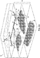
- Figure 2 illustrates a schematic view, partially in cross section of oilfield 200 having data acquisition tools 202.1, 202.2, 202.3 and 202.4 positioned at various locations along oilfield 200 for collecting data of subterranean formation 204 in accordance with implementations of various technologies and techniques described herein.
- Data acquisition tools 202.1-202.4 may be the same as data acquisition tools 106.1-106.4 of Figures 1A-1D , respectively, or others not depicted.
- data acquisition tools 202.1-202.4 generate data plots or measurements 208.1-208.4, respectively. These data plots are depicted along oilfield 200 to demonstrate the data generated by the various operations.
- Data plots 208.1-208.3 are examples of static data plots that may be generated by data acquisition tools 202.1-202.3, respectively; however, it should be understood that data plots 208.1-208.3 may also be data plots that are updated in real time. These measurements may be analyzed to better define the properties of the formation(s) and/or determine the accuracy of the measurements and/or for checking for errors. The plots of each of the respective measurements may be aligned and scaled for comparison and verification of the properties.
- Static data plot 208.1 is a seismic two-way response over a period of time.
- Static plot 208.2 is core sample data measured from a core sample of the formation 204.
- the core sample may be used to provide data, such as a graph of the density, porosity, permeability, or some other physical property of the core sample over the length of the core. Tests for density and viscosity may be performed on the fluids in the core at varying pressures and temperatures.
- Static data plot 208.3 is a logging trace that typically provides a resistivity or other measurement of the formation at various depths.
- a production decline curve or graph 208.4 is a dynamic data plot of the fluid flow rate over time.
- the production decline curve typically provides the production rate as a function of time.
- measurements are taken of fluid properties, such as flow rates, pressures, composition, etc.
- Other data may also be collected, such as historical data, user inputs, economic information, and/or other measurement data and other parameters of interest.
- the static and dynamic measurements may be analyzed and used to generate models of the subterranean formation to determine characteristics thereof. Similar measurements may also be used to measure changes in formation aspects over time.
- the subterranean structure 204 has a plurality of geological formations 206.1-206.4. As shown, this structure has several formations or layers, including a shale layer 206.1, a carbonate layer 206.2, a shale layer 206.3 and a sand layer 206.4. A fault 207 extends through the shale layer 206.1 and the carbonate layer 206.2.
- the static data acquisition tools are adapted to take measurements and detect characteristics of the formations.
- oilfield 200 may contain a variety of geological structures and/or formations, sometimes having extreme complexity. In some locations, typically below the water line, fluid may occupy pore spaces of the formations.
- Each of the measurement devices may be used to measure properties of the formations and/or its geological features. While each acquisition tool is shown as being in specific locations in oilfield 200, it will be appreciated that one or more types of measurement may be taken at one or more locations across one or more fields or other locations for comparison and/or analysis.
- seismic data displayed in static data plot 208.1 from data acquisition tool 202.1 is used by a geophysicist to determine characteristics of the subterranean formations and features.
- the core data shown in static plot 208.2 and/or log data from well log 208.3 are typically used by a geologist to determine various characteristics of the subterranean formation.
- the production data from graph 208.4 is typically used by the reservoir engineer to determine fluid flow reservoir characteristics.
- the data analyzed by the geologist, geophysicist and the reservoir engineer may be analyzed using modeling techniques.
- Figure 3A illustrates an oilfield 300 for performing production operations in accordance with implementations of various technologies and techniques described herein.
- the oilfield has a plurality of wellsites 302 operatively connected to central processing facility 354.
- the oilfield configuration of Figure 3A is not intended to limit the scope of the oilfield application system. Part, or all, of the oilfield may be on land and/or sea. Also, while a single oilfield with a single processing facility and a plurality of wellsites is depicted, any combination of one or more oilfields, one or more processing facilities and one or more wellsites may be present.
- Each wellsite 302 has equipment that forms wellbore 336 into the earth.
- the wellbores extend through subterranean formations 306 including reservoirs 304.
- These reservoirs 304 contain fluids, such as hydrocarbons.
- the wellsites draw fluid from the reservoirs and pass them to the processing facilities via surface networks 344.
- the surface networks 344 have tubing and control mechanisms for controlling the flow of fluids from the wellsite to processing facility 354.
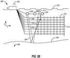
- Subsurface 362 includes seafloor surface 364.
- Seismic sources 366 may include marine sources such as vibroseis or airguns, which may propagate seismic waves 368 (e.g., energy signals) into the Earth over an extended period of time or at a nearly instantaneous energy provided by impulsive sources.
- the seismic waves may be propagated by marine sources as a frequency sweep signal.
- marine sources of the vibroseis type may initially emit a seismic wave at a low frequency (e.g., 5 Hz) and increase the seismic wave to a high frequency (e.g., 80-90Hz) overtime.
- the component(s) of the seismic waves 368 may be reflected and converted by seafloor surface 364 (i.e., reflector), and seismic wave reflections 370 may be received by a plurality of seismic receivers 372.
- Seismic receivers 372 may be disposed on a plurality of streamers (i.e., streamer array 374).
- the seismic receivers 372 may generate electrical signals representative of the received seismic wave reflections 370.
- the electrical signals may be embedded with information regarding the subsurface 362 and captured as a record of seismic data.
- each streamer may include streamer steering devices such as a bird, a deflector, a tail buoy and the like, which are not illustrated in this application.
- the streamer steering devices may be used to control the position of the streamers in accordance with the techniques described herein.
- seismic wave reflections 370 may travel upward and reach the water/air interface at the water surface 376, a portion of reflections 370 may then reflect downward again (i.e., sea-surface ghost waves 378) and be received by the plurality of seismic receivers 372.
- the sea-surface ghost waves 378 may be referred to as surface multiples.
- the point on the water surface 376 at which the wave is reflected downward is generally referred to as the downward reflection point.
- the electrical signals may be transmitted to a vessel 380 via transmission cables, wireless communication or the like.
- the vessel 380 may then transmit the electrical signals to a data processing center.
- the vessel 380 may include an onboard computer capable of processing the electrical signals (i.e., seismic data).
- seismic data i.e., seismic data
- surveys may be of formations deep beneath the surface.
- the formations may typically include multiple reflectors, some of which may include dipping events, and may generate multiple reflections (including wave conversion) for receipt by the seismic receivers 372.
- the seismic data may be processed to generate a seismic image of the subsurface 362.
- marine seismic acquisition systems tow each streamer in streamer array 374 at the same depth (e.g., 5-10m).
- marine based survey 360 may tow each streamer in streamer array 374 at different depths such that seismic data may be acquired and processed in a manner that avoids the effects of destructive interference due to sea-surface ghost waves.
- marine-based survey 360 of Figure 3B illustrates eight streamers towed by vessel 380 at eight different depths. The depth of each streamer may be controlled and maintained using the birds disposed on each streamer.
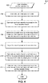
- FIG. 4 illustrates a flowchart of a method 400 for seismic processing, e.g., using a full waveform inversion, according to an embodiment.
- the method 400 includes obtaining seismic data, including a plurality of seismic waveforms, as at 402, e.g., as input.
- the seismic data may be acquired from one or more physical seismic acquisition devices, such as geophones, and may represent a physical subterranean formation, as generally described above. Further, the acquired seismic waveforms may be pre-processed, e.g., to remove noise therefrom, and/or any other suitable processing may be applied.
- the method 400 may also include acquiring simulated inversion data, as at 404.
- the simulated inversion data may be calculated based on an initial model of the subterranean formation.
- the model may be based on any available information about the subterranean formation that is known a priori, before the method 400 is conducted. This may include information about the subterranean formation, general characteristics of the seismic waveforms, etc.
- the method 400 further includes determining a model error by minimizing a local travel time shift error between the acquired seismic waveforms and the synthetic waveforms, as at 408. Additional details regarding embodiments of such determining the model error are described below with reference to Figure 5 .
- the method 400 includes adjusting the model based on the model error, as at 410. This may include, for example, adjusting the model such that the synthetic waveforms more closely match the acquired waveforms. In some embodiments, this may include time-shifting, phase-shifting, or in any other way, configuring the model such that the calculated, synthetic waveforms more closely match the acquired waveforms.
- the method 400 may loop back to 408 in order to perform a subsequent determination at 408 and model adjustment at 410.
- the blocks 408 and 410 may be part of an iterative loop that may continue until the model is adjusted, for example, by less than a threshold amount, for a set number of iterations, or based on any other measure.
- the method 400 also includes generating a velocity model by performing a full waveform inversion (FWI) for the acquired seismic waveforms, using the adjusted model (from the last iteration of 410) as the background model, as at 412. Any full waveform inversion technique may be applied; further, the full waveform inversion may be an iterative process.
- FWI full waveform inversion
- the method 400 may then include interpreting one or more characteristics of the subterranean formation based at least in part on the velocity model, as at 414.
- such interpretation may include identifying the location of seismic reflectors within the subterranean formation, which may be employed, e.g., after further processing, to determine the geology, lithology, etc. of the subterranean formation, e.g., to assist with oilfield development among other applications.
- the method 400 may also include performing other types of inversion techniques to the data.
- FWI techniques may include time-domain algorithms, which may scale to large 3D problems.
- J denotes the misfit functional
- model m stands for a set of possible subsurface Earth models
- data d 0 means the input observed data set
- F [ m ] stands for full waveform simulator/forward map, which simulates data by solving wave equations with finite difference algorithm on a possible subsurface model m .
- This non-linear inverse problem may be solved by an iterative non-linear conjugate gradient approach with a line search globalization strategy, and the gradient can be computed with the following equation (2).
- F [ m ] stands for the adjoint operator of the first derivative map of F [ m ], which may include backward propagation and an application of imaging condition.
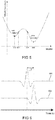
- FWI may in general, however, be an ill-posed nonlinear inverse problem, e.g. because of nonlinearity in the relation between acquired data and model, the degree of freedom, and imperfection of acquired data. Accordingly, there may be more than one model that, when an FWI is applied, may generate data within certain data-fitting tolerances, as Figure 5 shows. If FWI starts with the initial model 501, it will converge to the local minimum 502 on the left, instead of converging to the global minimum 503 on the right side. On the other hand, if FWI starts with the initial model 504, in the valley of the global minimum 503, the FWI process converges to the global minimum 503.
- Figure 6 illustrates a graph showing travel time shift ⁇ T as the mismatch between two signals 601, 602 in time, which may be relevant to cycle skipping determinations.
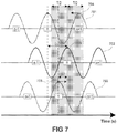
- Figure 7 illustrates three sinusoidal signals 701, 702, 703 that are mismatched, according to an embodiment. Cycle skipping may occur in FWI when the mismatch/travel-time shift between synthetic/calculated data and the observed/acquired data is larger than the half period of the dominant frequency. As Figure 7 shows, the mismatch between two sinusoidal signals, signal 701 (e.g., synthetic data) and signal 702 (e.g., observed data), L 1 , is larger than T/2. T is the period of the sinusoidal signal.
- FWI may bring the inversion in the opposite and wrong direction, while the objective function reduces.
- the mismatch of two signals L 2 is smaller than half period T/2.
- the inversion may align the peak (n) 706 of signal 703 with the peak (n) 704 of signal 702, and thus converge to the global minimum.
- the method 400 provides the control block 408, as described above, in which the initial model (background model) may be determined by minimizing the time shift as a local attribute.
- the initial model background model
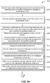
- Figure 8 there is illustrated a flowchart of a process 800 for performing the determination at 408 in Figure 4 , according to the invention.
- the process 800 includes determining a travel time shift objective function in the time domain, representing a travel time shift between at least one of the acquired waveforms and at least one of the synthetic waveforms, as at 802.
- the process 800 proceeds then to determining a local travel time shift error by directly minimizing the travel time shift objective function as a local attribute, as at 804.
- FWI may be modified to directly minimize travel time shift (equation (3)) between observed (acquired) and calculated (synthetic) data. This may be done instead of direct subtraction of the two, or by building an intermediate function or decomposing model spatially.
- the travel time shift ⁇ T between two signals may be proportional to the phase difference ⁇ 0 ⁇ of the signals ( d 0 is the observed data, d is the calculated data, and ⁇ is the frequency). Therefore, FWI may use a phase-based (e.g., phase-only) objective function to back project the phase error/difference into model error/perturbation.
- phase-based e.g., phase-only
- phase differences may be wrapped, and without an appropriate unwrapping process, the wrapped phase differences may lead to cycle skipping as well.
- noisy field data and acquisition realities may prevent, or at least impede, an accurate and robust phase unwrapping process to produce accurate unwrapped phase differences.
- the instantaneous phase difference may be computed, and used as an objective function in FWI, as shown in equations (5).
- calculating instantaneous phase difference in time domain may be prone to cycle skipping and poor signal to noise ratio issues etc.
- the instantaneous phase objective function might not allow recovery of background and low wavenumber components of the models, and thus may not overcome the cycle skipping issue (e.g., in field data).
- the process 800 thus includes identifying the correct travel time shift in time domain as a local attribute, as at 802, which is a function of time t in equation (6).
- the travel time shift objective function is then directly minimized, as at 804, yielding a local travel time shift error and as indicated in equation (6).
- the process 800 includes determining an instantaneous phase objective function relation based on the unwrapped instantaneous phase error, as at 808.
- ⁇ T ( t ) is the local travel time shift, which is a function of t between observed data d 0 ( t ) and calculated data d ( t )
- H is the Hilbert transform operator
- E is the instantaneous amplitude operator.
- FWI using the travel time shift objective function together with instantaneous phase relation may achieve successful inversion of the background/low wave-number components of the model, and may at least partially address the potential for cycle skipping.
- the field data testing shows this process 800 may result in better kinematic responses versus direct subtraction, phase-only objective function, and instantaneous phase objective function alone.
- the process 800 may be iterative.
- FIGS 9A and 9B illustrates a flowchart of a method 900 for seismic processing, according to an embodiment.
- the method 900 includes receiving seismic data including acquired seismic waveforms that were acquired from a seismic receiver and represent a subterranean area, as at 902 (e.g., Figure 4 , 402).
- the method 900 further includes generating synthetic waveforms based on an initial model of the subterranean area, as at 904 (e.g., Figure 4 , 406).
- the method 900 also includes determining a model error by minimizing a local travel time shift error between one or more of the acquired seismic waveforms and one or more of the synthetic waveforms, as at 906 (e.g., Figure 4 , 408: determine a model error by minimizing travel time shift; Figure 8 , process 800).
- Determining at 906 includes determining a travel time shift objective function in a time domain, as at 908 (e.g., Figure 8 , 802). Determining the travel time shift objective function represents a travel time shift between at least one of the acquired waveforms and at least one of the synthetic waveforms, as indicated at 910 (e.g., Figure 8 , 802). Determining the model error at 906 also includes determining a local travel time shift error, as at 912 (e.g., Figure 8 , 804). Determining the local travel time shift error includes directly minimizing the travel time shift objective function as a local attribute, as at 914 (e.g., Figure 8 , 804).
- Determining the model error at 906 further includes translating the local travel time shift error to an unwrapped instantaneous phase error, as at 916 (e.g., Figure 8 , 806). Determining the model error at 906 further includes back projecting the travel time shift error to the model error using the instantaneous phase objective function relation, as at 920 (e.g., Figure 8 , 810).
- the method 900 additionally includes adjusting the initial model based on the model error to generate an adjusted model, as at 922 (e.g., Figure 4 , 410).
- the method 900 further includes performing a full-waveform inversion using the adjusted model as a background model, as at 924 (e.g., Figure 4 , 412).
- the method 900 may additionally include interpreting one or more characteristics of the subterranean formation based on a result of the full-waveform inversion, as at 926 (e.g., Figure 4 , 414).
- any of the methods described herein may be executed by a computing system.
- Figure 10 illustrates an example of such a computing system 1000, in accordance with some embodiments.
- the computing system 1000 may include a computer or computer system 1001A, which may be an individual computer system 1001A or an arrangement of distributed computer systems.
- the computer system 1001A includes one or more analysis module(s) 1002 configured to perform various tasks according to some embodiments, such as one or more methods disclosed herein. To perform these various tasks, the analysis module 1002 executes independently, or in coordination with, one or more processors 1004, which is (or are) connected to one or more storage media 1006.
- the processor(s) 1004 is (or are) also connected to a network interface 10010 to allow the computer system 1001A to communicate over a data network 1009 with one or more additional computer systems and/or computing systems, such as 1001B, 1001C, and/or 1001D (note that computer systems 1001B, 1001C and/or 1001D may or may not share the same architecture as computer system 1001A, and may be located in different physical locations, e.g., computer systems 1001A and 1001B may be located in a processing facility, while in communication with one or more computer systems such as 1001C and/or 1001D that are located in one or more data centers, and/or located in varying countries on different continents).
- a processor can include a microprocessor, microcontroller, processor module or subsystem, programmable integrated circuit, programmable gate array, or another control or computing device.
- the storage media 1006 can be implemented as one or more computer-readable or machine-readable storage media. Note that while in the example embodiment of Figure 10 storage media 1006 is depicted as within computer system 1001A, in some embodiments, storage media 1006 may be distributed within and/or across multiple internal and/or external enclosures of computing system 1001A and/or additional computing systems.
- Storage media 1006 may include one or more different forms of memory including semiconductor memory devices such as dynamic or static random access memories (DRAMs or SRAMs), erasable and programmable read-only memories (EPROMs), electrically erasable and programmable read-only memories (EEPROMs) and flash memories, magnetic disks such as fixed, floppy and removable disks, other magnetic media including tape, optical media such as compact disks (CDs) or digital video disks (DVDs), BLURAY® disks, or other types of optical storage, or other types of storage devices.
- semiconductor memory devices such as dynamic or static random access memories (DRAMs or SRAMs), erasable and programmable read-only memories (EPROMs), electrically erasable and programmable read-only memories (EEPROMs) and flash memories
- magnetic disks such as fixed, floppy and removable disks, other magnetic media including tape
- optical media such as compact disks (CDs) or digital video disks (DVDs)
- DVDs digital video disks
- Such computer-readable or machine-readable storage medium or media is (are) considered to be part of an article (or article of manufacture).
- An article or article of manufacture can refer to any manufactured single component or multiple components.
- the storage medium or media can be located either in the machine running the machine-readable instructions, or located at a remote site from which machine-readable instructions can be downloaded over a network for execution.
- computing system 1000 contains one or more FWI inversion module(s) 1008, which may be configured to translate a travel-time shift error to an instantaneous phase error, according to an embodiment.
- computer system 1001A includes the FWI inversion module 1008.
- a single FWI inversion module may be used to perform some or all aspects of one or more embodiments of the methods described herein.
- a plurality of FWI inversion modules may be used to perform some or all aspects of methods described herein.
- computing system 1000 is only one example of a computing system, and that computing system 1000 may have more or fewer components than shown, may combine additional components not depicted in the example embodiment of Figure 10 , and/or computing system 1000 may have a different configuration or arrangement of the components depicted in Figure 10 .
- the various components shown in Figure 10 may be implemented in hardware, software, or a combination of both hardware and software, including one or more signal processing and/or application specific integrated circuits.
- steps in the processing methods described herein may be implemented by running one or more functional modules in information processing apparatus such as general purpose processors or application specific chips, such as ASICs, FPGAs, PLDs, or other appropriate devices.
- information processing apparatus such as general purpose processors or application specific chips, such as ASICs, FPGAs, PLDs, or other appropriate devices.
- Geologic interpretations, models and/or other interpretation aids may be refined in an iterative fashion; this concept is applicable to methods discussed herein.
- This can include use of feedback loops executed on an algorithmic basis, such as at a computing device (e.g., computing system 1000, Figure 10 ), and/or through manual control by a user who may make determinations regarding whether a given step, action, template, model, or set of curves has become sufficiently accurate for the evaluation of the subsurface three-dimensional geologic formation under consideration.
Landscapes
- Life Sciences & Earth Sciences (AREA)
- Engineering & Computer Science (AREA)
- Geology (AREA)
- Physics & Mathematics (AREA)
- Mining & Mineral Resources (AREA)
- Environmental & Geological Engineering (AREA)
- General Life Sciences & Earth Sciences (AREA)
- Remote Sensing (AREA)
- Fluid Mechanics (AREA)
- Geochemistry & Mineralogy (AREA)
- Geophysics (AREA)
- Acoustics & Sound (AREA)
- General Physics & Mathematics (AREA)
- Soil Sciences (AREA)
- Geophysics And Detection Of Objects (AREA)
Claims (4)
- Rechnerimplementiertes Verfahren (400, 800, 900) zur seismischen Prozessierung, um eine seismische Abbildung eines Untergrundbereichs zu generieren, umfassend:• Empfangen (402, 902) seismischer Daten, die erfasste seismische Wellenformen umfassen, die aus einem seismischen Empfänger erfasst wurden und den Untergrundbereich darstellen;• Generieren (406, 904) synthetischer Wellenformen basierend auf einem Anfangsmodell des Untergrundbereichs;• Bestimmen (408, 906) eines Modellfehlers;• Bereinigen (410, 922) des Anfangsmodells basierend auf dem Modellfehler, um ein bereinigtes Modell zu generieren; und• Durchführen einer Volle-Wellenform-Inversion (412, 924) unter Verwendung des bereinigten Modells als Hintergrundmodell, um die seismische Abbildung des Untergrundbereichs zu generieren;
dadurch gekennzeichnet, dass das Bestimmen des Modellfehlers umfasst:• Bestimmen (802, 908) einer Laufzeitverschiebungszielfunktion in einem Zeitbereich, wobei (910) die Laufzeitverschiebungszielfunktion eine Laufzeitverschiebung zwischen mindestens einer der erfassten Wellenformen und mindestens einer der synthetischen Wellenformen darstellt; und• Bestimmen (804, 912) eines lokalen Laufzeitverschiebungsfehlers durch direktes Minimieren der Laufzeitverschiebungszielfunktion als lokales Attribut;• Umrechnen (806, 916) des lokalen Laufzeitverschiebungsfehlers in einen Unwrapped-Momentanphasenfehler;• Bestimmen (808, 918) einer Momentanphasenzielfunktionsbeziehung basierend auf dem Unwrapped-Momentanphasenfehler; und• Rückprojizieren (810, 920) des Laufzeitverschiebungsfehlers in den Modellfehler unter Verwendung der Momentanphasenzielfunktionsbeziehung. - Verfahren nach Anspruch 1, ferner umfassend ein Interpretieren (414, 926) eines oder mehrerer Charakteristika des Untergrundbereichs basierend auf einem Ergebnis der Volle-Wellenform-Inversion.
- Rechensystem (1000), umfassend:• einen oder mehrere Prozessoren (1004); und• ein Speichersystem (1006), das ein oder mehrere nichtflüchtige rechnerlesbare Medien umfasst, die Anweisungen speichern, welche, wenn sie von wenigstens einem des einen oder der mehreren Prozessoren ausgeführt werden, bewirken, dass das Rechensystem das Verfahren nach einem der Ansprüche 1 oder 2, ausführt.
- Nichtflüchtiges rechnerlesbares Medium (1006), das Anweisungen speichert, die, wenn sie von mindestens einem Prozessor (1004) eines Rechensystems (1000) ausgeführt werden, bewirken, dass das Rechensystem das Verfahren nach einem der Ansprüche 1 oder 2 ausführt.
Applications Claiming Priority (2)
| Application Number | Priority Date | Filing Date | Title |
|---|---|---|---|
| US201462068024P | 2014-10-24 | 2014-10-24 | |
| PCT/US2015/057093 WO2016065247A1 (en) | 2014-10-24 | 2015-10-23 | Travel-time objective function for full waveform inversion |
Publications (3)
| Publication Number | Publication Date |
|---|---|
| EP3209859A1 EP3209859A1 (de) | 2017-08-30 |
| EP3209859A4 EP3209859A4 (de) | 2018-07-18 |
| EP3209859B1 true EP3209859B1 (de) | 2021-04-28 |
Family
ID=55761621
Family Applications (1)
| Application Number | Title | Priority Date | Filing Date |
|---|---|---|---|
| EP15852925.5A Active EP3209859B1 (de) | 2014-10-24 | 2015-10-23 | Wegzeitzielfunktion für vollwellenforminversion |
Country Status (3)
| Country | Link |
|---|---|
| US (1) | US10401516B2 (de) |
| EP (1) | EP3209859B1 (de) |
| WO (1) | WO2016065247A1 (de) |
Families Citing this family (14)
| Publication number | Priority date | Publication date | Assignee | Title |
|---|---|---|---|---|
| US20150081223A1 (en) * | 2013-09-19 | 2015-03-19 | Schlumberger Technology Corporation | Microseismic survey |
| SG11201608175SA (en) * | 2014-05-09 | 2016-11-29 | Exxonmobil Upstream Res Co | Efficient line search methods for multi-parameter full wavefield inversion |
| US10234582B2 (en) * | 2015-10-26 | 2019-03-19 | Geotomo Llc | Joint inversion of seismic data |
| EP3413092B1 (de) | 2017-06-08 | 2022-06-01 | Total Se | Verfahren zur evaluation einer geophysikalischen erfassungsgeometrie über einer region von interesse, zugehöriges verfahren, system und computerprogrammprodukt |
| US11624846B2 (en) * | 2017-09-21 | 2023-04-11 | The Regents Of The University Of California | Moment tensor reconstruction |
| US11194069B2 (en) | 2017-12-15 | 2021-12-07 | Halliburton Energy Services, Inc. | Systems and methods for high-resolution travel time and move-out velocity estimation using downhole linear receiver arrays |
| CN108563802B (zh) * | 2017-12-29 | 2021-12-17 | 中国海洋大学 | 一种提高地震转换波数值模拟精度的方法 |
| US11048001B2 (en) | 2018-03-30 | 2021-06-29 | Cgg Services Sas | Methods using travel-time full waveform inversion for imaging subsurface formations with salt bodies |
| CN108873066B (zh) * | 2018-06-26 | 2020-03-10 | 中国石油大学(华东) | 弹性介质波动方程反射波旅行时反演方法 |
| US11269098B2 (en) | 2018-08-31 | 2022-03-08 | Halliburton Energy Services, Inc. | Sparse deconvolution and inversion for formation properties |
| US11460593B2 (en) * | 2018-12-13 | 2022-10-04 | Halliburton Energy Services, Inc. | Mitigation of seismic multiples in seismic data using inversion |
| WO2021174178A1 (en) * | 2020-02-27 | 2021-09-02 | Schlumberger Technology Corporation | Template matching full-waveform inversion |
| US11467299B2 (en) | 2020-12-16 | 2022-10-11 | Saudi Arabian Oil Company | Full waveform inversion velocity guided first arrival picking |
| WO2022221179A1 (en) * | 2021-04-12 | 2022-10-20 | Board Of Regents, The University Of Texas System | A starting model independent full waveform inversion system, method, and computer-program product for subsurface velocity estimation |
Family Cites Families (31)
| Publication number | Priority date | Publication date | Assignee | Title |
|---|---|---|---|---|
| US5570321A (en) * | 1994-03-03 | 1996-10-29 | Atlantic Richfield Company | Seismic velocity model optimization method using simulated annearling to determine prestack travel-times |
| US5838634A (en) * | 1996-04-04 | 1998-11-17 | Exxon Production Research Company | Method of generating 3-D geologic models incorporating geologic and geophysical constraints |
| US6160758A (en) * | 1996-06-28 | 2000-12-12 | Scientific Innovations, Inc. | Utilization of auto and cross-correlation functions in methods for locating a source of a primary signal and for localizing signals |
| US7373252B2 (en) * | 2005-11-04 | 2008-05-13 | Western Geco L.L.C. | 3D pre-stack full waveform inversion |
| US7937224B2 (en) * | 2006-05-17 | 2011-05-03 | Westerngeco L.L.C. | Diplet-based seismic processing |
| GB0722469D0 (en) * | 2007-11-16 | 2007-12-27 | Statoil Asa | Forming a geological model |
| EA017177B1 (ru) * | 2008-03-21 | 2012-10-30 | Эксонмобил Апстрим Рисерч Компани | Эффективный способ инверсии геофизических данных |
| AU2009335964B2 (en) * | 2009-01-09 | 2015-05-14 | Exxonmobil Upstream Research Company | Hydrocarbon detection with passive seismic data |
| CA2767757A1 (en) | 2009-09-09 | 2011-03-17 | Conocophillips Company | Dip guided full waveform inversion |
| US9244181B2 (en) * | 2009-10-19 | 2016-01-26 | Westerngeco L.L.C. | Full-waveform inversion in the traveltime domain |
| US9013956B2 (en) * | 2009-10-27 | 2015-04-21 | Chevron U.S.A Inc. | Method and system for seismic imaging and earth modeling using beam tomography |
| US8223587B2 (en) | 2010-03-29 | 2012-07-17 | Exxonmobil Upstream Research Company | Full wavefield inversion using time varying filters |
| US20110320180A1 (en) * | 2010-06-29 | 2011-12-29 | Al-Saleh Saleh M | Migration Velocity Analysis of Seismic Data Using Common Image Cube and Green's Functions |
| US8437998B2 (en) * | 2010-09-27 | 2013-05-07 | Exxonmobil Upstream Research Company | Hybrid method for full waveform inversion using simultaneous and sequential source method |
| SG188191A1 (en) * | 2010-09-27 | 2013-04-30 | Exxonmobil Upstream Res Co | Simultaneous source encoding and source separation as a practical solution for full wavefield inversion |
| CA2810960A1 (en) * | 2010-09-28 | 2012-04-05 | Rene-Edouard Andre Michel Plessix | Earth model estimation through an acoustic full waveform inversion of seismic data |
| WO2012058626A1 (en) * | 2010-10-29 | 2012-05-03 | Schlumberger Canada Limited | Model based inversion of seismic response for determining formation properties |
| WO2012141799A2 (en) * | 2011-02-25 | 2012-10-18 | University Of Florida Research Foundation, Inc. | Detection of sinkholes or anomalies |
| US8700372B2 (en) * | 2011-03-10 | 2014-04-15 | Schlumberger Technology Corporation | Method for 3-D gravity forward modeling and inversion in the wavenumber domain |
| US9158018B2 (en) | 2011-04-05 | 2015-10-13 | Westerngeco L.L.C. | Waveform inversion using a response of forward modeling |
| US9075159B2 (en) * | 2011-06-08 | 2015-07-07 | Chevron U.S.A., Inc. | System and method for seismic data inversion |
| ES2869401T3 (es) * | 2011-07-12 | 2021-10-25 | Colorado School Of Mines | Análisis de velocidad de migración de ecuación de onda usando deformación de imágenes |
| CA2841775C (en) * | 2011-07-19 | 2018-09-11 | Halliburton Energy Services, Inc. | System and method for moment tensor migration imaging |
| US9268047B2 (en) * | 2012-10-12 | 2016-02-23 | Rock Solid Images, Inc | Geophysical surveying |
| AU2013392659B2 (en) * | 2013-06-18 | 2017-06-15 | Halliburton Energy Services, Inc. | Methods and systems for seismic data analysis using a tilted transversely isotropic (TTI) model |
| US20150081223A1 (en) * | 2013-09-19 | 2015-03-19 | Schlumberger Technology Corporation | Microseismic survey |
| US20150109885A1 (en) * | 2013-09-26 | 2015-04-23 | Conocophillips Company | Method for correcting first break arrival time |
| WO2015118414A2 (en) * | 2014-01-14 | 2015-08-13 | Cgg Services Sa | Detecting and estimating anisotropy errors using full waveform inversion and ray based tomography |
| US9568627B2 (en) * | 2014-05-15 | 2017-02-14 | Acoustic Zoom, Inc. | System and method for adaptive classification and filtering for imaging diffused energy from the earths subsurface |
| US20160047924A1 (en) * | 2014-08-14 | 2016-02-18 | Christine Krohn | Determination of Subsurface Properties in the Vicinity of a Well by Full Wavefield Inversion |
| US10386511B2 (en) * | 2014-10-03 | 2019-08-20 | Exxonmobil Upstream Research Company | Seismic survey design using full wavefield inversion |
-
2015
- 2015-10-23 WO PCT/US2015/057093 patent/WO2016065247A1/en active Application Filing
- 2015-10-23 EP EP15852925.5A patent/EP3209859B1/de active Active
- 2015-10-23 US US15/521,592 patent/US10401516B2/en active Active
Non-Patent Citations (1)
| Title |
|---|
| None * |
Also Published As
| Publication number | Publication date |
|---|---|
| US20170242142A1 (en) | 2017-08-24 |
| EP3209859A1 (de) | 2017-08-30 |
| EP3209859A4 (de) | 2018-07-18 |
| US10401516B2 (en) | 2019-09-03 |
| WO2016065247A1 (en) | 2016-04-28 |
Similar Documents
| Publication | Publication Date | Title |
|---|---|---|
| EP3209859B1 (de) | Wegzeitzielfunktion für vollwellenforminversion | |
| EP3058169B1 (de) | Iteratives stapeln von seismischen bildpartitionen | |
| US10422906B2 (en) | Modeling and filtering coherent noise in seismic surveys | |
| US9983323B2 (en) | Performing tomography to build orthorhombic models | |
| US9784867B2 (en) | Seismic data processing | |
| US20220066061A1 (en) | Combining noise attenuation and wavefield reconstruction in seismic processing | |
| EP3215872B1 (de) | Kompensation von räumlicher und slowness-/winkelunschärfe von reflektivität | |
| US11531128B2 (en) | Reconstruction of multi-shot, multi-channel seismic wavefields | |
| EP3555671B1 (de) | Interpolation von seismischen daten mit zeitvarianten standorten | |
| US11237284B2 (en) | Single streamer deghosting with extended model space | |
| US20190346580A1 (en) | Horizon-Based Splitting Intensity Inversion for Anisotropic Characterization of A Target Volume | |
| US20230118111A1 (en) | Template matching full-waveform inversion | |
| CA3214288A1 (en) | Automatic salt geometry detection in a subsurface volume | |
| CA3225979A1 (en) | Direct arrival replacement for seismic imaging | |
| WO2023250477A1 (en) | Transfer learning for ml-assisted seismic interpretation | |
| WO2023043925A1 (en) | Systems and methods for modeling a subsurface volume using time-lapse data | |
| AU2022332224A1 (en) | Time lapse data reconstruction and time lapse data acquisition survey design for co2 monitoring |
Legal Events
| Date | Code | Title | Description |
|---|---|---|---|
| STAA | Information on the status of an ep patent application or granted ep patent |
Free format text: STATUS: THE INTERNATIONAL PUBLICATION HAS BEEN MADE |
|
| PUAI | Public reference made under article 153(3) epc to a published international application that has entered the european phase |
Free format text: ORIGINAL CODE: 0009012 |
|
| STAA | Information on the status of an ep patent application or granted ep patent |
Free format text: STATUS: REQUEST FOR EXAMINATION WAS MADE |
|
| 17P | Request for examination filed |
Effective date: 20170421 |
|
| AK | Designated contracting states |
Kind code of ref document: A1 Designated state(s): AL AT BE BG CH CY CZ DE DK EE ES FI FR GB GR HR HU IE IS IT LI LT LU LV MC MK MT NL NO PL PT RO RS SE SI SK SM TR |
|
| AX | Request for extension of the european patent |
Extension state: BA ME |
|
| DAV | Request for validation of the european patent (deleted) | ||
| DAX | Request for extension of the european patent (deleted) | ||
| A4 | Supplementary search report drawn up and despatched |
Effective date: 20180614 |
|
| RIC1 | Information provided on ipc code assigned before grant |
Ipc: E21B 49/00 20060101ALI20180608BHEP Ipc: G01V 1/40 20060101ALI20180608BHEP Ipc: E21B 43/017 20060101ALI20180608BHEP Ipc: G06F 19/00 20110101ALI20180608BHEP Ipc: E21B 49/02 20060101ALI20180608BHEP Ipc: G01V 1/28 20060101ALI20180608BHEP Ipc: E21B 43/30 20060101ALI20180608BHEP Ipc: G01V 1/30 20060101ALI20180608BHEP Ipc: E21B 47/00 20120101AFI20180608BHEP Ipc: G05B 19/02 20060101ALI20180608BHEP Ipc: E21B 47/12 20120101ALN20180608BHEP |
|
| STAA | Information on the status of an ep patent application or granted ep patent |
Free format text: STATUS: EXAMINATION IS IN PROGRESS |
|
| 17Q | First examination report despatched |
Effective date: 20200515 |
|
| REG | Reference to a national code |
Ref country code: DE Ref legal event code: R079 Ref document number: 602015068787 Country of ref document: DE Free format text: PREVIOUS MAIN CLASS: E21B0047000000 Ipc: G01V0001300000 |
|
| GRAP | Despatch of communication of intention to grant a patent |
Free format text: ORIGINAL CODE: EPIDOSNIGR1 |
|
| STAA | Information on the status of an ep patent application or granted ep patent |
Free format text: STATUS: GRANT OF PATENT IS INTENDED |
|
| RIC1 | Information provided on ipc code assigned before grant |
Ipc: E21B 43/30 20060101ALI20201124BHEP Ipc: G01V 1/30 20060101AFI20201124BHEP Ipc: G01V 1/28 20060101ALI20201124BHEP Ipc: E21B 43/017 20060101ALI20201124BHEP |
|
| INTG | Intention to grant announced |
Effective date: 20201211 |
|
| GRAS | Grant fee paid |
Free format text: ORIGINAL CODE: EPIDOSNIGR3 |
|
| GRAA | (expected) grant |
Free format text: ORIGINAL CODE: 0009210 |
|
| STAA | Information on the status of an ep patent application or granted ep patent |
Free format text: STATUS: THE PATENT HAS BEEN GRANTED |
|
| AK | Designated contracting states |
Kind code of ref document: B1 Designated state(s): AL AT BE BG CH CY CZ DE DK EE ES FI FR GB GR HR HU IE IS IT LI LT LU LV MC MK MT NL NO PL PT RO RS SE SI SK SM TR |
|
| REG | Reference to a national code |
Ref country code: GB Ref legal event code: FG4D |
|
| REG | Reference to a national code |
Ref country code: CH Ref legal event code: EP |
|
| REG | Reference to a national code |
Ref country code: DE Ref legal event code: R096 Ref document number: 602015068787 Country of ref document: DE |
|
| REG | Reference to a national code |
Ref country code: AT Ref legal event code: REF Ref document number: 1387707 Country of ref document: AT Kind code of ref document: T Effective date: 20210515 |
|
| REG | Reference to a national code |
Ref country code: IE Ref legal event code: FG4D |
|
| REG | Reference to a national code |
Ref country code: LT Ref legal event code: MG9D |
|
| REG | Reference to a national code |
Ref country code: AT Ref legal event code: MK05 Ref document number: 1387707 Country of ref document: AT Kind code of ref document: T Effective date: 20210428 |
|
| PG25 | Lapsed in a contracting state [announced via postgrant information from national office to epo] |
Ref country code: BG Free format text: LAPSE BECAUSE OF FAILURE TO SUBMIT A TRANSLATION OF THE DESCRIPTION OR TO PAY THE FEE WITHIN THE PRESCRIBED TIME-LIMIT Effective date: 20210728 Ref country code: AT Free format text: LAPSE BECAUSE OF FAILURE TO SUBMIT A TRANSLATION OF THE DESCRIPTION OR TO PAY THE FEE WITHIN THE PRESCRIBED TIME-LIMIT Effective date: 20210428 Ref country code: HR Free format text: LAPSE BECAUSE OF FAILURE TO SUBMIT A TRANSLATION OF THE DESCRIPTION OR TO PAY THE FEE WITHIN THE PRESCRIBED TIME-LIMIT Effective date: 20210428 Ref country code: FI Free format text: LAPSE BECAUSE OF FAILURE TO SUBMIT A TRANSLATION OF THE DESCRIPTION OR TO PAY THE FEE WITHIN THE PRESCRIBED TIME-LIMIT Effective date: 20210428 Ref country code: LT Free format text: LAPSE BECAUSE OF FAILURE TO SUBMIT A TRANSLATION OF THE DESCRIPTION OR TO PAY THE FEE WITHIN THE PRESCRIBED TIME-LIMIT Effective date: 20210428 Ref country code: NL Free format text: LAPSE BECAUSE OF FAILURE TO SUBMIT A TRANSLATION OF THE DESCRIPTION OR TO PAY THE FEE WITHIN THE PRESCRIBED TIME-LIMIT Effective date: 20210428 |
|
| PG25 | Lapsed in a contracting state [announced via postgrant information from national office to epo] |
Ref country code: RS Free format text: LAPSE BECAUSE OF FAILURE TO SUBMIT A TRANSLATION OF THE DESCRIPTION OR TO PAY THE FEE WITHIN THE PRESCRIBED TIME-LIMIT Effective date: 20210428 Ref country code: SE Free format text: LAPSE BECAUSE OF FAILURE TO SUBMIT A TRANSLATION OF THE DESCRIPTION OR TO PAY THE FEE WITHIN THE PRESCRIBED TIME-LIMIT Effective date: 20210428 Ref country code: PT Free format text: LAPSE BECAUSE OF FAILURE TO SUBMIT A TRANSLATION OF THE DESCRIPTION OR TO PAY THE FEE WITHIN THE PRESCRIBED TIME-LIMIT Effective date: 20210830 Ref country code: PL Free format text: LAPSE BECAUSE OF FAILURE TO SUBMIT A TRANSLATION OF THE DESCRIPTION OR TO PAY THE FEE WITHIN THE PRESCRIBED TIME-LIMIT Effective date: 20210428 Ref country code: NO Free format text: LAPSE BECAUSE OF FAILURE TO SUBMIT A TRANSLATION OF THE DESCRIPTION OR TO PAY THE FEE WITHIN THE PRESCRIBED TIME-LIMIT Effective date: 20210728 Ref country code: LV Free format text: LAPSE BECAUSE OF FAILURE TO SUBMIT A TRANSLATION OF THE DESCRIPTION OR TO PAY THE FEE WITHIN THE PRESCRIBED TIME-LIMIT Effective date: 20210428 Ref country code: IS Free format text: LAPSE BECAUSE OF FAILURE TO SUBMIT A TRANSLATION OF THE DESCRIPTION OR TO PAY THE FEE WITHIN THE PRESCRIBED TIME-LIMIT Effective date: 20210828 Ref country code: GR Free format text: LAPSE BECAUSE OF FAILURE TO SUBMIT A TRANSLATION OF THE DESCRIPTION OR TO PAY THE FEE WITHIN THE PRESCRIBED TIME-LIMIT Effective date: 20210729 |
|
| REG | Reference to a national code |
Ref country code: NL Ref legal event code: MP Effective date: 20210428 |
|
| PG25 | Lapsed in a contracting state [announced via postgrant information from national office to epo] |
Ref country code: EE Free format text: LAPSE BECAUSE OF FAILURE TO SUBMIT A TRANSLATION OF THE DESCRIPTION OR TO PAY THE FEE WITHIN THE PRESCRIBED TIME-LIMIT Effective date: 20210428 Ref country code: DK Free format text: LAPSE BECAUSE OF FAILURE TO SUBMIT A TRANSLATION OF THE DESCRIPTION OR TO PAY THE FEE WITHIN THE PRESCRIBED TIME-LIMIT Effective date: 20210428 Ref country code: CZ Free format text: LAPSE BECAUSE OF FAILURE TO SUBMIT A TRANSLATION OF THE DESCRIPTION OR TO PAY THE FEE WITHIN THE PRESCRIBED TIME-LIMIT Effective date: 20210428 Ref country code: SM Free format text: LAPSE BECAUSE OF FAILURE TO SUBMIT A TRANSLATION OF THE DESCRIPTION OR TO PAY THE FEE WITHIN THE PRESCRIBED TIME-LIMIT Effective date: 20210428 Ref country code: SK Free format text: LAPSE BECAUSE OF FAILURE TO SUBMIT A TRANSLATION OF THE DESCRIPTION OR TO PAY THE FEE WITHIN THE PRESCRIBED TIME-LIMIT Effective date: 20210428 Ref country code: ES Free format text: LAPSE BECAUSE OF FAILURE TO SUBMIT A TRANSLATION OF THE DESCRIPTION OR TO PAY THE FEE WITHIN THE PRESCRIBED TIME-LIMIT Effective date: 20210428 Ref country code: RO Free format text: LAPSE BECAUSE OF FAILURE TO SUBMIT A TRANSLATION OF THE DESCRIPTION OR TO PAY THE FEE WITHIN THE PRESCRIBED TIME-LIMIT Effective date: 20210428 |
|
| REG | Reference to a national code |
Ref country code: DE Ref legal event code: R097 Ref document number: 602015068787 Country of ref document: DE |
|
| PLBE | No opposition filed within time limit |
Free format text: ORIGINAL CODE: 0009261 |
|
| STAA | Information on the status of an ep patent application or granted ep patent |
Free format text: STATUS: NO OPPOSITION FILED WITHIN TIME LIMIT |
|
| 26N | No opposition filed |
Effective date: 20220131 |
|
| REG | Reference to a national code |
Ref country code: DE Ref legal event code: R119 Ref document number: 602015068787 Country of ref document: DE |
|
| PG25 | Lapsed in a contracting state [announced via postgrant information from national office to epo] |
Ref country code: IS Free format text: LAPSE BECAUSE OF FAILURE TO SUBMIT A TRANSLATION OF THE DESCRIPTION OR TO PAY THE FEE WITHIN THE PRESCRIBED TIME-LIMIT Effective date: 20210828 Ref country code: AL Free format text: LAPSE BECAUSE OF FAILURE TO SUBMIT A TRANSLATION OF THE DESCRIPTION OR TO PAY THE FEE WITHIN THE PRESCRIBED TIME-LIMIT Effective date: 20210428 |
|
| REG | Reference to a national code |
Ref country code: CH Ref legal event code: PL |
|
| REG | Reference to a national code |
Ref country code: BE Ref legal event code: MM Effective date: 20211031 |
|
| PG25 | Lapsed in a contracting state [announced via postgrant information from national office to epo] |
Ref country code: MC Free format text: LAPSE BECAUSE OF FAILURE TO SUBMIT A TRANSLATION OF THE DESCRIPTION OR TO PAY THE FEE WITHIN THE PRESCRIBED TIME-LIMIT Effective date: 20210428 |
|
| PG25 | Lapsed in a contracting state [announced via postgrant information from national office to epo] |
Ref country code: LU Free format text: LAPSE BECAUSE OF NON-PAYMENT OF DUE FEES Effective date: 20211023 Ref country code: IT Free format text: LAPSE BECAUSE OF FAILURE TO SUBMIT A TRANSLATION OF THE DESCRIPTION OR TO PAY THE FEE WITHIN THE PRESCRIBED TIME-LIMIT Effective date: 20210428 Ref country code: DE Free format text: LAPSE BECAUSE OF NON-PAYMENT OF DUE FEES Effective date: 20220503 Ref country code: BE Free format text: LAPSE BECAUSE OF NON-PAYMENT OF DUE FEES Effective date: 20211031 |
|
| PG25 | Lapsed in a contracting state [announced via postgrant information from national office to epo] |
Ref country code: LI Free format text: LAPSE BECAUSE OF NON-PAYMENT OF DUE FEES Effective date: 20211031 Ref country code: CH Free format text: LAPSE BECAUSE OF NON-PAYMENT OF DUE FEES Effective date: 20211031 |
|
| PG25 | Lapsed in a contracting state [announced via postgrant information from national office to epo] |
Ref country code: IE Free format text: LAPSE BECAUSE OF NON-PAYMENT OF DUE FEES Effective date: 20211023 |
|
| PG25 | Lapsed in a contracting state [announced via postgrant information from national office to epo] |
Ref country code: HU Free format text: LAPSE BECAUSE OF FAILURE TO SUBMIT A TRANSLATION OF THE DESCRIPTION OR TO PAY THE FEE WITHIN THE PRESCRIBED TIME-LIMIT; INVALID AB INITIO Effective date: 20151023 |
|
| PG25 | Lapsed in a contracting state [announced via postgrant information from national office to epo] |
Ref country code: CY Free format text: LAPSE BECAUSE OF FAILURE TO SUBMIT A TRANSLATION OF THE DESCRIPTION OR TO PAY THE FEE WITHIN THE PRESCRIBED TIME-LIMIT Effective date: 20210428 |
|
| PGFP | Annual fee paid to national office [announced via postgrant information from national office to epo] |
Ref country code: GB Payment date: 20230831 Year of fee payment: 9 |
|
| PGFP | Annual fee paid to national office [announced via postgrant information from national office to epo] |
Ref country code: FR Payment date: 20230911 Year of fee payment: 9 |
|
| P01 | Opt-out of the competence of the unified patent court (upc) registered |
Effective date: 20231208 |
|
| PG25 | Lapsed in a contracting state [announced via postgrant information from national office to epo] |
Ref country code: MK Free format text: LAPSE BECAUSE OF FAILURE TO SUBMIT A TRANSLATION OF THE DESCRIPTION OR TO PAY THE FEE WITHIN THE PRESCRIBED TIME-LIMIT Effective date: 20210428 |