EP3209856B1 - Abhilfeschaffender zementierpacker auf zweiter stufe - Google Patents
Abhilfeschaffender zementierpacker auf zweiter stufe Download PDFInfo
- Publication number
- EP3209856B1 EP3209856B1 EP15787860.4A EP15787860A EP3209856B1 EP 3209856 B1 EP3209856 B1 EP 3209856B1 EP 15787860 A EP15787860 A EP 15787860A EP 3209856 B1 EP3209856 B1 EP 3209856B1
- Authority
- EP
- European Patent Office
- Prior art keywords
- nails
- packer assembly
- inner casing
- cement
- cement packer
- Prior art date
- Legal status (The legal status is an assumption and is not a legal conclusion. Google has not performed a legal analysis and makes no representation as to the accuracy of the status listed.)
- Not-in-force
Links
Images

Classifications
-
- E—FIXED CONSTRUCTIONS
- E21—EARTH OR ROCK DRILLING; MINING
- E21B—EARTH OR ROCK DRILLING; OBTAINING OIL, GAS, WATER, SOLUBLE OR MELTABLE MATERIALS OR A SLURRY OF MINERALS FROM WELLS
- E21B33/00—Sealing or packing boreholes or wells
- E21B33/10—Sealing or packing boreholes or wells in the borehole
- E21B33/13—Methods or devices for cementing, for plugging holes, crevices or the like
- E21B33/138—Plastering the borehole wall; Injecting into the formation
-
- E—FIXED CONSTRUCTIONS
- E21—EARTH OR ROCK DRILLING; MINING
- E21B—EARTH OR ROCK DRILLING; OBTAINING OIL, GAS, WATER, SOLUBLE OR MELTABLE MATERIALS OR A SLURRY OF MINERALS FROM WELLS
- E21B33/00—Sealing or packing boreholes or wells
- E21B33/10—Sealing or packing boreholes or wells in the borehole
- E21B33/13—Methods or devices for cementing, for plugging holes, crevices or the like
- E21B33/14—Methods or devices for cementing, for plugging holes, crevices or the like for cementing casings into boreholes
- E21B33/146—Stage cementing, i.e. discharging cement from casing at different levels
-
- E—FIXED CONSTRUCTIONS
- E21—EARTH OR ROCK DRILLING; MINING
- E21B—EARTH OR ROCK DRILLING; OBTAINING OIL, GAS, WATER, SOLUBLE OR MELTABLE MATERIALS OR A SLURRY OF MINERALS FROM WELLS
- E21B33/00—Sealing or packing boreholes or wells
- E21B33/10—Sealing or packing boreholes or wells in the borehole
- E21B33/12—Packers; Plugs
- E21B33/129—Packers; Plugs with mechanical slips for hooking into the casing
-
- E—FIXED CONSTRUCTIONS
- E21—EARTH OR ROCK DRILLING; MINING
- E21B—EARTH OR ROCK DRILLING; OBTAINING OIL, GAS, WATER, SOLUBLE OR MELTABLE MATERIALS OR A SLURRY OF MINERALS FROM WELLS
- E21B23/00—Apparatus for displacing, setting, locking, releasing or removing tools, packers or the like in boreholes or wells
- E21B23/06—Apparatus for displacing, setting, locking, releasing or removing tools, packers or the like in boreholes or wells for setting packers
Definitions
- the present invention relates generally to downhole tools for use in subterranean wells, and more specifically to a tool for use in cementing operations within a subterranean well.
- a subterranean well such as a well used in hydrocarbon development
- the upper portion of the well have the largest diameter casing, which can be cased and cemented in one step.
- casing For deeper wells, such as, for example, wells that are 1524 metres (5000 feet) deep or more, in the lower part of the well smaller diameter inner casing is run to the bottom of the drilled hole and cemented in two stages.
- the bottom most part of the casing is cemented using traditional means, such as by pumping cement through the casing shoe.
- An upper portion can be cemented using a second-stage tool, which is sometimes referred to as a multi-stage tool.
- the second-stage tool can be associated with the inner casing and includes an annular packer that seals the annular space between the inner casing and the bore of the well or an outer casing.
- the annular packer isolates a lower part of the annular space from the upper part of the annular space which is above the annular packer.
- the second-stage tool has ports that extend through the inner casing to allow circulating fluids to flow through the ports and into the upper part of the annular space.
- the second-stage cementing process allows the cement to enter the annular space at a distance above the bottom of the well, preventing the entire hydraulic pressure of the weight of the column of cement being exerted on the bottom of the well. It also enables cementing the upper part of the hole in case a low pressure zone, known as loss circulation zone, is encountered in the middle portion of the well.
- the first step of the two stage cementing can be performed by pumping enough cement into the lower part of the annular space and up to the depth of the second-stage tool, or to the depth of loss circulation zone, as applicable.
- the annular packer is set to isolate the lower part of the annulus, and the ports are opened to circulate cement into the annular space above the annular packer.
- Mechanical and hydraulic means can be used to set, to open, and to close the second-stage cementing tools depending on the model of second-stage tool used.
- the second-stage tool can fail to open, leaving the annular space above the second-stage tool without cement. Such failure results in significant cost increases and time delays and affects the condition of the well. If alternate means for cementing the annular space are not possible, the upper part of the inner casing is left non-cemented, which will shorten the well life significantly. Traditional methods to mitigate the failure are complicated procedures and can result in substandard well conditions or can result in changing the well design to less than desired casing sizes and reducing well integrity.
- a cement bond log can be run to determine the level of cement in the annular space.
- the inner casing can be perforated above the second-stage tool and a cement retainer packer can be run above the perforations.
- Cement can be circulated through the new perforations into the upper annular space.
- the perforations can then be scabbed off with smaller casing, which procedure is mandatory in some countries, or with casing patches where allowed. Forming the perforations risks damaging the next casing or the outer casing and introduces safety risks with the handling of explosive material required for the perforation gun.
- a method and apparatus for providing a local seal are described in FR 868771 .
- the method consists of introducing the sealing product directly into the annular space through holes perforated by means of tubulars or plugs applied against the wall of the box in front of these orifices.
- the device uses bodies to perforate the casing at the desired locations, tubulars are applied in a leak tight manner in holes drilled in the casing and used to bring sealant out of the casing.
- cement can be dumped into the annual space from the surface. This can result in substandard quality cement.
- Embodiments of the present disclosure provide systems and methods that can perform each of the required functions of sealing across the inner casing, creating holes through the inner casing, and then sealing the holes through the inner casing. Embodiments of this disclosure can also be easily repeated in case of failure. The systems and methods of this disclosure do not require explosive materials and eliminate the need of extra casing or patches to seal the holes through the inner casing.
- a method for cementing an annular space outside of an inner casing of a subterranean well includes running and setting a cement packer assembly into a bore of the inner casing.
- the cement packer assembly includes a plurality of nails spaced around a circumference of the cement packer assembly. Slips are set and a lower end of each of the nails is pushed through the inner casing with a setting tool coupled to the cement packer assembly, each of the nails forming a hole through the inner casing. A middle portion of the nails is positioned within the holes, the middle portion of the nails having a smaller outer dimension than the outer dimension of the lower end of the nails.
- Cement is pumped through the inner casing, through the holes, and into the annular space. A force is applied to the nails to move the nails through the holes and position a seal plate of each nail against an inside surface of the bore surrounding one of the holes.
- the cement packer assembly after running and setting a cement packer assembly into a bore of the inner casing, can be isolated from fluids and pressure within the bore by setting a lower seal that extends across the bore and by setting an upper seal that has a ring shape and circumscribes the setting tool.
- the step of running and setting the cement packer assembly into the bore of the inner casing can include setting the cement packer axially above a failed second-stage cement tool or axially above an annular packer that seals the annular space.
- the cement packer assembly can be run into the bore of the inner casing with a drill pipe.
- the step of the setting slips and pushing the lower end of each of the nails through the inner casing, with the setting tool can be accomplished by rotating the setting tool.
- the force can be applied to the nails by landing a dart in a landing seat of the cement packer assembly.
- the step of pushing the lower end of each of the nails through the inner casing can include engaging a sloped surface of the cement packer assembly with each of the nails, pushing the lower end of each of the nails through the inner casing at an angle relative to a central axis.
- the step of applying a force to the nails to move the nails through the holes and position a seal plate of each nail against an inside surface of the bore surrounding one of the holes can include positioning a nail seal of each nail within one of the holes.
- the method can further include de-coupling the setting tool from the cement packer assembly and retrieving the setting tool, and then drilling out the cement packer assembly.
- a method for cementing an annular space between an inner casing and an outer casing of a subterranean well includes running a cement packer assembly into a bore of the inner casing above an annular packer that seals the annular space.
- the cement packer assembly includes a plurality of nails spaced around a circumference of the cement packer assembly. Axial movement of the cement packer assembly is prevented by setting slips of the cement packer assembly to engage an inner surface of the bore. A lower end of each of the nails is pushed through the inner casing with a setting tool coupled to the cement packer assembly, each of the nails forming a hole through the inner casing. A middle portion of the nails is positioned within the holes.
- the middle portion of the nails has a smaller outer dimension than the outer dimension of the lower end of the nails.
- Cement is pumped through the inner casing, through the holes and into the annular space.
- Each of the holes is sealed with a nail seal of each nail and a seal plate of each nail by moving each of the nails through one of the holes to position the seal plate of each nail against an inside surface of the bore surrounding one of the holes and locating each of the nail seals within one of the holes.
- the lower end of each of the nails is spaced apart from the outer casing.
- the cement packer assembly after running the cement packer assembly into the bore, can be isolated from fluids and pressure within the bore, by setting a lower seal that extends across the bore and by setting an upper seal that has a ring shape and circumscribes the setting tool.
- the step of sealing each of the holes includes landing a dart in a landing seat of the cement packer assembly to apply a downward force to each of the nails.
- the step of pushing the lower end of each of the nails through the inner casing can include engaging a sloped surface of the cement packer assembly with each of the nails and pushing the lower end of each of the nails through the inner casing at an angle relative to a central axis.
- the method can further include de-coupling the setting tool from the cement packer assembly and retrieving the setting tool with a drill pipe, then drilling out the cement packer assembly.
- an apparatus for cementing an annular space outside of an inner casing of a subterranean well includes a cement packer assembly.
- the cement packer assembly has a plurality of nails spaced around a circumference of the cement packer assembly, each of the nails having a lower end and a middle portion with a smaller outer dimension than an outer dimension of the lower end.
- the cement packer assembly also has slips having outer surfaces selectively engaging an inner surface of a bore of the inner casing.
- a seal plate is associated with each nail, the seal plate having a curved outer surface for mating with the inner surface of the bore.
- a setting tool is coupled to the cement packer assembly.
- the cement packer assembly also has a sloped surface selectively directing the lower end of each of the nails through the inner casing at an angle relative to a central axis so that each of the nails forms a hole in the inner casing.
- the apparatus can have a lower seal that extends across the bore and an upper seal that has a ring shape and circumscribes the setting tool.
- the cement packer assembly can also have a landing seat selectively receiving a dart landed in the cement packer assembly to move each of the nails through one of a plurality of holes through the inner casing to position a seal plate of each nail against an inside surface of the bore surrounding one of the holes.
- Each nail can have a nail seal selectively sealingly positioned within one of a plurality of holes through the inner casing.
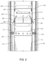
- cement packer assembly 10 is shown being lowered into inner casing 12 of a subterranean well 14 along central axis Ax.
- Inner casing 12 can be located concentrically within outer casing 16, as shown, or alternately can be located within an uncased well bore, defining annular space 17 outside of inner casing 12.
- Cement packer assembly can be coupled to setting tool 18 and run into bore 20 of inner casing 12 on drill pipe 22.
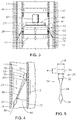
- Cement packer assembly 10 includes a plurality of nails 24 that are spaced around a circumference of cement packer assembly 10. Looking now at Figures 4-5 , each nail 24 has lower end 26. Lower end 26 of nail 24 has a sharp pointed end for piercing inner casing 12. Lower end 26 has an increased outer dimension adjacent to the sharp pointed end. Lower end 26 can have a generally diamond shaped cross section, as shown, or alternately can have an arrow shape in cross section, an upside down tear drop shape in cross section, or other type of cross section that has a sharp pointed end followed by an increased outer dimension. If nail 24 is symmetrical about nail axis 38, then the outer dimensions will be outer diameters.
- Each nail 24 also has middle portion 28. Middle portion 28 has a smaller outer dimension than the increased outer dimension of lower end 26.
- Each nail 24 further includes an upper nail assembly 30.
- Upper nail assembly 30 is at an end of nail 24 on an opposite side of middle portion 28 than lower end 26.
- Upper nail assembly 30 includes nail seal 32 and seal plate 34.
- Nail seal 32 is a sealing member and has a cross sectional dimension that is at least as large as the increased outer dimension of lower end 26.
- Nail seal 32 can be formed of rubber or other elastomeric material that can form a seal and maintain such seal at the working temperatures and pressures of the subterranean well.
- Seal plate 34 is an arc shaped segment of plate. Seal plate 34 can have an outer surface that has a radius of curvature that matches a radius of curvature of the inner surface of bore 20. The height H and width W of the outer surface of seal plate 34 are each larger than the increased outer dimension of lower end 26 of nail 24.
- a plate axis 36 that extends in the direction of the height H of seal plate 34 is set at an angle 40 relative to nail axis 38 that extends along nail 24. Plate axis 36 is parallel to central axis Ax. The length of nail 24 along nail axis 38 is such that when seal plate 34 engages the inner surface of bore 20, lower end 26 of nail 24 does not extend to outer casing 16, but is instead spaced apart from outer casing 16.
- cement packer assembly 10 has sloped surface 41.
- Sloped surface 41 has an outer surface that is set at an angle about the same as, or substantially similar to, angle 40 so that lower end 26 of nail 24 can slidingly engage sloped surface 41 and nail 24 can be directed along sloped surface 41.
- Sloped surface 41 can be, for example, a frusto conical surface within cement packer assembly 10 having a larger circumference at a lower end of sloped surface 41 than the circumference of sloped surface 41 at an upper end of sloped surface 41.
- Cement packer assembly 10 also includes slips 42.
- Slips 42 have outer surfaces that can engage the inner surface of bore 20.
- Slips 42 can have teeth that bite into the inner surface of bore 20 and are shaped to resist upward movement of cement packer assembly 10 relative to inner casing 12, or resist downward movement of cement packer assembly 10 relative to inner casing 12.
- slips 42 can be spaced radially inward from the inner surface of bore 20.
- Slips 42 can be set by setting tool 18, such as, for example, by rotation of setting tool 18.
- slips 42 at an upper end of cement packer assembly 10 resist upward movement of cement packer assembly 10 relative to inner casing 12 and slips 42 located at a lower end of cement packer assembly 10 resist downward movement of cement packer assembly 10 relative to inner casing 12.
- cement packer assembly 10 also has lower seal 44 and upper seal 46.
- Lower seal 44 can extend across bore 20, sealing and isolating cement packer assembly 10 from fluids and pressure located within bore 20 axially below lower seal 44.
- Upper seal 46 is a ring shaped seal that circumscribes setting tool 18, forming a seal around setting tool 18 and between setting tool 18 and bore 20.
- Upper seal 46 isolates cement packer assembly 10 from fluids and pressure located within bore 20 axially above upper seal 46.
- the outer dimension of both lower seal 44 and upper seal 46 can be spaced radially inward from the inner surface of bore 20.
- Cement packer assembly 10 additionally includes landing seat 48.
- Landing seat 48 is located axially between lower seal 44 and upper seal 46.
- Landing seat 48 is shaped to accept dart 50 and to move axially downward relative to lower seal 44 and upper seal 46 when dart 50 is landed on landing seat 48.
- Nails 24 can be attached to landing seat 48 with shear pin assemblies (not shown). The shear pin assemblies can allow for some relative movement between landing seat 48 and nails 24, but will retain nails 24 in a desired position until shear members of the shear pin assemblies are sheared.
- Dart 50 is formed of a drillable material.
- cement packer assembly 10 can be threaded together, in a manner known in the art.
- setting tool 18 can be connected to cement packer assembly 10, by methods known in the industry, for example, by J-Sleeve, pressure rated pins or tension sleeves.
- cement packer assembly 10 can be run into bore 20 of inner casing 12.
- Cement packer assembly 10 can be coupled to setting tool 18 and run into bore 20 with drill pipe 22. Looking at Figure 2 , cement packer assembly 10 can be set axially above failed second-stage cement tool 52 or above an existing annular packer 54 that seals annular space 17.
- Cement packer assembly 10 can then be isolated from fluids and pressure within bore 20 by setting lower seal 44 and upper seal 46.
- Lower seal 44 and upper seal 46 can be set by conventional methods, such as by using a tension sleeve (not shown) that is rotated clockwise and counter clockwise by setting tool 18.
- Slips 41 can then be set to resist and prevent axial movement of cement packer assembly 10 relative to bore 20. This can be accomplished, for example, by rotating setting tool 18.
- Slips 41 can be set by conventional means, such as by rotation of setting tool 18 clockwise and counterclockwise.
- Lower end 26 of each nail 24 can then be pushed through inner casing 12 to form a hole 56 through inner casing 12. This can also be accomplished, for example, with the rotation of setting tool 18 clockwise and counterclockwise.
- As nails 24 move axially downward to form holes 56 lower end 26 of each nail can engage sloped surface 41 of cement packer assembly 10 so that nails 24 extend through inner casing 12 at angle 40 relative to a plate axis 36 and central axis A
- each nail 24 will continue through inner casing 12 until lower end 26 is located within annular space 17.
- Middle portion 28 of each nail 24 will be positioned in one of the holes 56. Because middle portion 28 has a smaller outer dimension than the outer dimension of lower end 26, there is open space within each hole 56 around middle portion 28.
- Cement can then be pumped through drill pipe 22, into cement packer assembly 10, and out into annular space 17 by way of holes 56. Because existing annular packer 54 seals annular space 17 below cement packer assembly 10, the cement will fill annular space 17 axially above existing annular packer 54 and cement packer assembly 10.
- the shear pin assemblies, or other connection means, between landing seat 48 and nails 24 will retain nails 24 in the desired position with middle portion 28 of each nail 24 positioned in one of the holes 56.
- Setting tool 18 can then be de-coupled from cement packer assembly 10 and retrieved by pulling drill pipe 22 out of bore 20.
- the remaining components of cement packer assembly 10, including landing seat 48, sloped surface 41, and lower seal 44 and upper seal 46, as well as dart 50 can be drilled out, each of such components being formed of a drillable material.
- the integrity of the seal across holes 56 can be tested.
- cement packer assembly 10 can perform each of the required functions of isolating cement packer assembly 10 within inner casing 12, creating holes 56 through the inner casing 12, and then after cementing operations, sealing holes 56 through inner casing 12.
Landscapes
- Life Sciences & Earth Sciences (AREA)
- Engineering & Computer Science (AREA)
- Geology (AREA)
- Mining & Mineral Resources (AREA)
- Physics & Mathematics (AREA)
- Environmental & Geological Engineering (AREA)
- Fluid Mechanics (AREA)
- General Life Sciences & Earth Sciences (AREA)
- Geochemistry & Mineralogy (AREA)
- Consolidation Of Soil By Introduction Of Solidifying Substances Into Soil (AREA)
Claims (15)
- Verfahren zum Zementieren eines ringförmigen Raums (17) außerhalb eines Innengehäuses (12) eines unterirdischen Bohrlochs (14), wobei das Verfahren Folgendes umfasst:(a) Einführen und Setzen einer Zementierpackeranordnung (10) in eine Bohrung (20) des Innengehäuses, wobei die Zementierpackeranordnung eine Vielzahl von Nägeln (24) beinhaltet, die um einen Umfang der Zementierpackeranordnung beabstandet sind;(b) Setzen von Abfangkeilen (42) und Drücken eines unteren Endes (26) jedes der Nägel mit einem Setzwerkzeug (18), das an die Zementierpackeranordnung gekoppelt ist, durch das Innengehäuse, wobei jeder der Nägel ein Loch (56) durch das Innengehäuse bildet;(c) Ausrichten eines mittleren Abschnitts (28) der Nägel in den Löchern, wobei der mittlere Abschnitt der Nägel eine kleinere Außenabmessung als die Außenabmessung des unteren Endes der Nägel aufweist;(d) Pumpen von Zement durch das Innengehäuse, durch die Löcher und in den ringförmigen Raum und(e) Aufbringen einer Kraft auf die Nägel, um die Nägel durch die Löcher zu bewegen, und Positionieren einer Dichtplatte (34) jedes der Nägel gegen eine Innenfläche der Bohrung, die eines der Löcher umgibt.
- Verfahren nach Anspruch 1, das nach Schritt (a) durch Setzen einer unteren Dichtung (44), die sich über die Bohrung erstreckt, und durch Setzen einer oberen Dichtung (46), die eine Ringform aufweist und das Setzwerkzeug (18) umschließt, das Isolieren der Zementierpackeranordnung (10) gegenüber Fluiden und Druck in der Bohrung (20) umfasst.
- Verfahren nach Anspruch 1 oder 2, wobei Schritt (e) ferner das Positionieren einer Nageldichtung (32) jedes Nagels (24) in einem der Löcher (56) umfasst.
- Verfahren nach einem der Ansprüche 1-3, wobei der Schritt des Einführens und Setzens der Zementierpackeranordnung (10) in die Bohrung (20) des Innengehäuses (12) Folgendes beinhaltet:(i) Setzen des Zementierpackers axial über ein Zementierwerkzeug (52) mit ausgefallener zweiter Stufe und/oder(ii) Setzen des Zementierpackers axial über einen ringförmigen Packer (54), der den ringförmigen Raum (17) abdichtet; und/oder(iii) Einführen der Zementierpackeranordnung mit einem Bohrrohr (22) in die Bohrung.
- Verfahren nach einem der Ansprüche 1-4, wobei der Schritt des:(i) Aufbringens der Kraft auf die Nägel (24) das Landen eines Pfeils (50) in einem Landesitz (48) der Zementierpackeranordnung (10) umfasst und/oder(ii) Drückens des unteren Endes (26) jedes der Nägel durch das Innengehäuse (12) das Eingreifen einer geneigten Fläche (41) der Zementierpackeranordnung in jeden der Nägel beinhaltet, derart, dass das untere Ende jedes der Nägel in einem Winkel relativ zu einer Mittelachse (Ax) durch das Innengehäuse gedrückt wird.
- Verfahren nach einem der Ansprüche 1-5, wobei der Schritt des Setzens von Abfangkeilen (42) und des Drückens des unteren Endes (26) jedes der Nägel (24) durch das Innengehäuse (12) mit dem Setzwerkzeug (18) das Drehen des Setzwerkzeugs umfasst.
- Verfahren nach einem der Ansprüche 1-6, das ferner das Entkoppeln des Setzwerkzeugs (18) von der Zementierpackeranordnung (10) und das Zurückziehen des Setzwerkzeugs und das Ausbohren der Zementierpackeranordnung umfasst.
- Verfahren zum Zementieren eines ringförmigen Raums (17) zwischen einem Innengehäuse (12) und einem Außengehäuse (16) eines unterirdischen Bohrlochs (14), wobei das Verfahren Folgendes umfasst:(a) Einführen einer Zementierpackeranordnung (10) in eine Bohrung (20) des Innengehäuses über einen ringförmigen Packer (54), der den ringförmigen Raum abdichtet, wobei die Zementierpackeranordnung eine Vielzahl von Nägeln (24) beinhaltet, die um einen Umfang der Zementierpackeranordnung beabstandet sind;(b) Verhindern einer Axialbewegung der Zementierpackeranordnung durch Setzen von Abfangkeilen (42) der Zementierpackeranordnung, um in eine Innenfläche der Bohrung einzugreifen;(c) Drücken eines unteren Endes (26) jedes der Nägel mit einem Setzwerkzeug (18), das an die Zementierpackeranordnung gekoppelt ist, durch das Innengehäuse, wobei jeder der Nägel ein Loch (56) durch das Innengehäuse bildet;(d) Ausrichten eines mittleren Abschnitts (28) der Nägel in den Löchern, wobei der mittlere Abschnitt der Nägel eine kleinere Außenabmessung als die Außenabmessung des unteren Endes der Nägel aufweist;(e) Pumpen von Zement durch das Innengehäuse, durch die Löcher und in den ringförmigen Raum und(f) Abdichten jedes der Löcher mit einer Nageldichtung (32) jedes Nagels und einer Dichtplatte (34) jedes Nagels durch Bewegen jedes der Nägel durch eines der Löcher, um die Dichtplatte jedes Nagels gegen eine Innenfläche der Bohrung, die eines der Löcher umgibt, zu positionieren, und Einsetzen jeder der Nageldichtungen in eines der Löcher, wobei das untere Ende jedes der Nägel vom Außengehäuse beabstandet ist.
- Verfahren nach Anspruch 8, wobei der Schritt des Abdichtens jedes der Löcher (56) das Landen eines Pfeils (50) in einen Landesitz (48) der Zementierpackeranordnung (10) beinhaltet, um auf jeden der Nägel (24) eine Abwärtskraft aufzubringen.
- Verfahren nach Anspruch 8 oder 9, wobei der Schritt des Drückens des unteren Endes (26) jedes der Nägel (24) durch das Innengehäuse (12) das Eingreifen einer geneigten Fläche (41) der Zementierpackeranordnung (10) in jeden der Nägel beinhaltet, indem das untere Ende jedes der Nägel in einem Winkel relativ zu einer Mittelachse (Ax) durch das Innengehäuse gedrückt wird.
- Verfahren nach einem der Ansprüche 8-10, das ferner Folgendes umfasst:(i) nach Schritt (a) durch Setzen einer unteren Dichtung (44), die sich über die Bohrung erstreckt, und durch Setzen einer oberen Dichtung (46), die eine Ringform aufweist und das Setzwerkzeug (18) umschließt, Isolieren der Zementierpackeranordnung (10) gegenüber Fluiden und Druck in der Bohrung (20) und/oder(ii) Entkoppeln des Setzwerkzeugs von der Zementierpackeranordnung und Zurückziehen des Setzwerkzeugs mit einem Bohrrohr (22) und dann Ausbohren der Zementierpackeranordnung.
- Vorrichtung zum Zementieren eines ringförmigen Raums (17) außerhalb eines Innengehäuses (12) eines unterirdischen Bohrlochs (14), wobei die Vorrichtung Folgendes umfasst:eine Zementierpackeranordnung (10) mit:einer Vielzahl von Nägeln (24), die um einen Umfang der Zementierpackeranordnung beabstandet sind, wobei jeder der Nägel ein unteres Ende (26) und einen mittleren Abschnitt (28) mit einer kleineren Außenabmessung als eine Außenabmessung des unteren Endes aufweist;Abfangkeilen (42) mit Außenflächen, die selektiv in eine Innenfläche einer Bohrung (20) des Innengehäuses eingreifen; undeiner Dichtplatte (34), die mit jedem Nagel verknüpft ist, wobei die Dichtplatte eine gekrümmte Außenfläche zum Anpassen an die Innenfläche der Bohrung aufweist;einem Setzwerkzeug (18), das an die Zementierpackeranordnung gekoppelt ist; undeiner geneigten Fläche (41), die das untere Ende jedes der Nägel in einem Winkel relativ zu einer Mittelachse (Ax) selektiv durch das Innengehäuse leitet, derart, dass jeder der Nägel ein Loch (56) im Innengehäuse bildet.
- Vorrichtung nach Anspruch 12, die ferner eine untere Dichtung (44) umfasst, die sich über die Bohrung (20) erstreckt, und eine obere Dichtung (46), die eine Ringform aufweist und das Setzwerkzeug (18) umschließt.
- Vorrichtung nach Anspruch 12 oder 13, wobei die Zementierpackeranordnung (10) einen Landesitz (48) aufweist, der selektiv einen Pfeil (50) aufnimmt, der in die Zementierpackeranordnung gelandet wird, um jeden der Nägel (24) durch eines einer Vielzahl von Löchern (56) durch das Innengehäuse (12) zu bewegen, um eine Dichtplatte (34) jedes Nagels gegen eine Innenfläche der Bohrung (20), die eines der Löcher umgibt, zu positionieren.
- Vorrichtung nach einem der Ansprüche 12-14, wobei jeder Nagel (24) eine Nageldichtung (32) aufweist, die selektiv abdichtend in einem einer Vielzahl von Löchern (56) durch das Innengehäuse (12) positioniert wird.
Applications Claiming Priority (2)
| Application Number | Priority Date | Filing Date | Title |
|---|---|---|---|
| US14/521,721 US9797219B2 (en) | 2014-10-23 | 2014-10-23 | Remedial second-stage cementing packer |
| PCT/US2015/056957 WO2016065170A1 (en) | 2014-10-23 | 2015-10-22 | Remedial second-stage cementing packer |
Publications (2)
| Publication Number | Publication Date |
|---|---|
| EP3209856A1 EP3209856A1 (de) | 2017-08-30 |
| EP3209856B1 true EP3209856B1 (de) | 2018-11-28 |
Family
ID=54365460
Family Applications (1)
| Application Number | Title | Priority Date | Filing Date |
|---|---|---|---|
| EP15787860.4A Not-in-force EP3209856B1 (de) | 2014-10-23 | 2015-10-22 | Abhilfeschaffender zementierpacker auf zweiter stufe |
Country Status (4)
| Country | Link |
|---|---|
| US (1) | US9797219B2 (de) |
| EP (1) | EP3209856B1 (de) |
| SA (1) | SA517381347B1 (de) |
| WO (1) | WO2016065170A1 (de) |
Families Citing this family (1)
| Publication number | Priority date | Publication date | Assignee | Title |
|---|---|---|---|---|
| CN109869114B (zh) * | 2017-12-01 | 2021-09-17 | 中石化石油工程技术服务有限公司 | 一种封隔式分级注水泥器及其作业方法 |
Family Cites Families (8)
| Publication number | Priority date | Publication date | Assignee | Title |
|---|---|---|---|---|
| FR868771A (fr) | 1940-09-06 | 1942-01-15 | Schlumberger Prospection | Méthode et dispositifs pour sceller localement les tubes de sondage dans le terrain |
| US5178219A (en) * | 1991-06-27 | 1993-01-12 | Halliburton Company | Method and apparatus for performing a block squeeze cementing job |
| US7000697B2 (en) | 2001-11-19 | 2006-02-21 | Schlumberger Technology Corporation | Downhole measurement apparatus and technique |
| US20090301720A1 (en) | 2006-01-24 | 2009-12-10 | Jonathan Paul Edwards | Remote plugging device for wells |
| RU2386013C1 (ru) | 2008-06-24 | 2010-04-10 | Общество с ограниченной ответственностью "Бурение" (ООО "Бурение") | Способ цементирования верхней ступени обсадной колонны в скважине |
| CN201460798U (zh) | 2009-06-04 | 2010-05-12 | 濮阳市科锐机械工程技术有限公司 | 一种新型静压封隔器 |
| NO332439B1 (no) | 2010-10-26 | 2012-09-17 | Subsea P&A As | Fremgangsmåte og anordning for å plugge en undervannsbrønn |
| CN202596642U (zh) | 2012-05-15 | 2012-12-12 | 中国石油天然气股份有限公司 | 循环压井套管打孔装置 |
-
2014
- 2014-10-23 US US14/521,721 patent/US9797219B2/en active Active
-
2015
- 2015-10-22 WO PCT/US2015/056957 patent/WO2016065170A1/en not_active Ceased
- 2015-10-22 EP EP15787860.4A patent/EP3209856B1/de not_active Not-in-force
-
2017
- 2017-04-17 SA SA517381347A patent/SA517381347B1/ar unknown
Non-Patent Citations (1)
| Title |
|---|
| None * |
Also Published As
| Publication number | Publication date |
|---|---|
| US20160115752A1 (en) | 2016-04-28 |
| WO2016065170A1 (en) | 2016-04-28 |
| SA517381347B1 (ar) | 2022-12-20 |
| US9797219B2 (en) | 2017-10-24 |
| EP3209856A1 (de) | 2017-08-30 |
Similar Documents
| Publication | Publication Date | Title |
|---|---|---|
| US11946333B2 (en) | Cup plug having a large flow-through inside diameter | |
| US9765594B2 (en) | Apparatus and method for stimulating subterranean formations | |
| US10689926B2 (en) | Lost circulation zone isolating liner | |
| US20080135248A1 (en) | Method and apparatus for completing and fluid treating a wellbore | |
| US20100263857A1 (en) | Composite Cement Retainer | |
| CN104968888A (zh) | 多级井隔离和断裂 | |
| WO2016174239A1 (en) | Downhole system | |
| US11142987B2 (en) | Annular barrier system | |
| US10006267B2 (en) | Expansion cone for downhole tool | |
| US20170175485A1 (en) | Downhole system | |
| EP3209856B1 (de) | Abhilfeschaffender zementierpacker auf zweiter stufe | |
| CN105765158A (zh) | 改善的用于可变形的套筒的填充机构 | |
| US9228407B2 (en) | Apparatus and method for completing a wellbore | |
| US10119382B2 (en) | Burst plug assembly with choke insert, fracturing tool and method of fracturing with same | |
| US20180371881A1 (en) | Tool, method and system for well services | |
| EP3216975A1 (de) | Bohrlochsystem |
Legal Events
| Date | Code | Title | Description |
|---|---|---|---|
| STAA | Information on the status of an ep patent application or granted ep patent |
Free format text: STATUS: THE INTERNATIONAL PUBLICATION HAS BEEN MADE |
|
| PUAI | Public reference made under article 153(3) epc to a published international application that has entered the european phase |
Free format text: ORIGINAL CODE: 0009012 |
|
| STAA | Information on the status of an ep patent application or granted ep patent |
Free format text: STATUS: REQUEST FOR EXAMINATION WAS MADE |
|
| 17P | Request for examination filed |
Effective date: 20170428 |
|
| AK | Designated contracting states |
Kind code of ref document: A1 Designated state(s): AL AT BE BG CH CY CZ DE DK EE ES FI FR GB GR HR HU IE IS IT LI LT LU LV MC MK MT NL NO PL PT RO RS SE SI SK SM TR |
|
| AX | Request for extension of the european patent |
Extension state: BA ME |
|
| DAV | Request for validation of the european patent (deleted) | ||
| DAX | Request for extension of the european patent (deleted) | ||
| STAA | Information on the status of an ep patent application or granted ep patent |
Free format text: STATUS: EXAMINATION IS IN PROGRESS |
|
| 17Q | First examination report despatched |
Effective date: 20180223 |
|
| GRAP | Despatch of communication of intention to grant a patent |
Free format text: ORIGINAL CODE: EPIDOSNIGR1 |
|
| STAA | Information on the status of an ep patent application or granted ep patent |
Free format text: STATUS: GRANT OF PATENT IS INTENDED |
|
| INTG | Intention to grant announced |
Effective date: 20180706 |
|
| GRAS | Grant fee paid |
Free format text: ORIGINAL CODE: EPIDOSNIGR3 |
|
| GRAA | (expected) grant |
Free format text: ORIGINAL CODE: 0009210 |
|
| STAA | Information on the status of an ep patent application or granted ep patent |
Free format text: STATUS: THE PATENT HAS BEEN GRANTED |
|
| AK | Designated contracting states |
Kind code of ref document: B1 Designated state(s): AL AT BE BG CH CY CZ DE DK EE ES FI FR GB GR HR HU IE IS IT LI LT LU LV MC MK MT NL NO PL PT RO RS SE SI SK SM TR |
|
| REG | Reference to a national code |
Ref country code: CH Ref legal event code: EP |
|
| REG | Reference to a national code |
Ref country code: DE Ref legal event code: R096 Ref document number: 602015020555 Country of ref document: DE |
|
| REG | Reference to a national code |
Ref country code: AT Ref legal event code: REF Ref document number: 1070463 Country of ref document: AT Kind code of ref document: T Effective date: 20181215 |
|
| REG | Reference to a national code |
Ref country code: IE Ref legal event code: FG4D |
|
| REG | Reference to a national code |
Ref country code: NL Ref legal event code: MP Effective date: 20181128 |
|
| REG | Reference to a national code |
Ref country code: LT Ref legal event code: MG4D |
|
| REG | Reference to a national code |
Ref country code: AT Ref legal event code: MK05 Ref document number: 1070463 Country of ref document: AT Kind code of ref document: T Effective date: 20181128 |
|
| PG25 | Lapsed in a contracting state [announced via postgrant information from national office to epo] |
Ref country code: LV Free format text: LAPSE BECAUSE OF FAILURE TO SUBMIT A TRANSLATION OF THE DESCRIPTION OR TO PAY THE FEE WITHIN THE PRESCRIBED TIME-LIMIT Effective date: 20181128 Ref country code: AT Free format text: LAPSE BECAUSE OF FAILURE TO SUBMIT A TRANSLATION OF THE DESCRIPTION OR TO PAY THE FEE WITHIN THE PRESCRIBED TIME-LIMIT Effective date: 20181128 Ref country code: ES Free format text: LAPSE BECAUSE OF FAILURE TO SUBMIT A TRANSLATION OF THE DESCRIPTION OR TO PAY THE FEE WITHIN THE PRESCRIBED TIME-LIMIT Effective date: 20181128 Ref country code: HR Free format text: LAPSE BECAUSE OF FAILURE TO SUBMIT A TRANSLATION OF THE DESCRIPTION OR TO PAY THE FEE WITHIN THE PRESCRIBED TIME-LIMIT Effective date: 20181128 Ref country code: FI Free format text: LAPSE BECAUSE OF FAILURE TO SUBMIT A TRANSLATION OF THE DESCRIPTION OR TO PAY THE FEE WITHIN THE PRESCRIBED TIME-LIMIT Effective date: 20181128 Ref country code: BG Free format text: LAPSE BECAUSE OF FAILURE TO SUBMIT A TRANSLATION OF THE DESCRIPTION OR TO PAY THE FEE WITHIN THE PRESCRIBED TIME-LIMIT Effective date: 20190228 Ref country code: LT Free format text: LAPSE BECAUSE OF FAILURE TO SUBMIT A TRANSLATION OF THE DESCRIPTION OR TO PAY THE FEE WITHIN THE PRESCRIBED TIME-LIMIT Effective date: 20181128 Ref country code: IS Free format text: LAPSE BECAUSE OF FAILURE TO SUBMIT A TRANSLATION OF THE DESCRIPTION OR TO PAY THE FEE WITHIN THE PRESCRIBED TIME-LIMIT Effective date: 20190328 |
|
| REG | Reference to a national code |
Ref country code: NO Ref legal event code: T2 Effective date: 20181128 |
|
| PG25 | Lapsed in a contracting state [announced via postgrant information from national office to epo] |
Ref country code: RS Free format text: LAPSE BECAUSE OF FAILURE TO SUBMIT A TRANSLATION OF THE DESCRIPTION OR TO PAY THE FEE WITHIN THE PRESCRIBED TIME-LIMIT Effective date: 20181128 Ref country code: PT Free format text: LAPSE BECAUSE OF FAILURE TO SUBMIT A TRANSLATION OF THE DESCRIPTION OR TO PAY THE FEE WITHIN THE PRESCRIBED TIME-LIMIT Effective date: 20190328 Ref country code: GR Free format text: LAPSE BECAUSE OF FAILURE TO SUBMIT A TRANSLATION OF THE DESCRIPTION OR TO PAY THE FEE WITHIN THE PRESCRIBED TIME-LIMIT Effective date: 20190301 Ref country code: AL Free format text: LAPSE BECAUSE OF FAILURE TO SUBMIT A TRANSLATION OF THE DESCRIPTION OR TO PAY THE FEE WITHIN THE PRESCRIBED TIME-LIMIT Effective date: 20181128 Ref country code: SE Free format text: LAPSE BECAUSE OF FAILURE TO SUBMIT A TRANSLATION OF THE DESCRIPTION OR TO PAY THE FEE WITHIN THE PRESCRIBED TIME-LIMIT Effective date: 20181128 |
|
| PG25 | Lapsed in a contracting state [announced via postgrant information from national office to epo] |
Ref country code: NL Free format text: LAPSE BECAUSE OF FAILURE TO SUBMIT A TRANSLATION OF THE DESCRIPTION OR TO PAY THE FEE WITHIN THE PRESCRIBED TIME-LIMIT Effective date: 20181128 |
|
| PG25 | Lapsed in a contracting state [announced via postgrant information from national office to epo] |
Ref country code: DK Free format text: LAPSE BECAUSE OF FAILURE TO SUBMIT A TRANSLATION OF THE DESCRIPTION OR TO PAY THE FEE WITHIN THE PRESCRIBED TIME-LIMIT Effective date: 20181128 Ref country code: PL Free format text: LAPSE BECAUSE OF FAILURE TO SUBMIT A TRANSLATION OF THE DESCRIPTION OR TO PAY THE FEE WITHIN THE PRESCRIBED TIME-LIMIT Effective date: 20181128 Ref country code: CZ Free format text: LAPSE BECAUSE OF FAILURE TO SUBMIT A TRANSLATION OF THE DESCRIPTION OR TO PAY THE FEE WITHIN THE PRESCRIBED TIME-LIMIT Effective date: 20181128 Ref country code: IT Free format text: LAPSE BECAUSE OF FAILURE TO SUBMIT A TRANSLATION OF THE DESCRIPTION OR TO PAY THE FEE WITHIN THE PRESCRIBED TIME-LIMIT Effective date: 20181128 |
|
| REG | Reference to a national code |
Ref country code: DE Ref legal event code: R097 Ref document number: 602015020555 Country of ref document: DE |
|
| PG25 | Lapsed in a contracting state [announced via postgrant information from national office to epo] |
Ref country code: SK Free format text: LAPSE BECAUSE OF FAILURE TO SUBMIT A TRANSLATION OF THE DESCRIPTION OR TO PAY THE FEE WITHIN THE PRESCRIBED TIME-LIMIT Effective date: 20181128 Ref country code: EE Free format text: LAPSE BECAUSE OF FAILURE TO SUBMIT A TRANSLATION OF THE DESCRIPTION OR TO PAY THE FEE WITHIN THE PRESCRIBED TIME-LIMIT Effective date: 20181128 Ref country code: SM Free format text: LAPSE BECAUSE OF FAILURE TO SUBMIT A TRANSLATION OF THE DESCRIPTION OR TO PAY THE FEE WITHIN THE PRESCRIBED TIME-LIMIT Effective date: 20181128 Ref country code: RO Free format text: LAPSE BECAUSE OF FAILURE TO SUBMIT A TRANSLATION OF THE DESCRIPTION OR TO PAY THE FEE WITHIN THE PRESCRIBED TIME-LIMIT Effective date: 20181128 |
|
| PLBE | No opposition filed within time limit |
Free format text: ORIGINAL CODE: 0009261 |
|
| STAA | Information on the status of an ep patent application or granted ep patent |
Free format text: STATUS: NO OPPOSITION FILED WITHIN TIME LIMIT |
|
| PG25 | Lapsed in a contracting state [announced via postgrant information from national office to epo] |
Ref country code: SI Free format text: LAPSE BECAUSE OF FAILURE TO SUBMIT A TRANSLATION OF THE DESCRIPTION OR TO PAY THE FEE WITHIN THE PRESCRIBED TIME-LIMIT Effective date: 20181128 |
|
| 26N | No opposition filed |
Effective date: 20190829 |
|
| PG25 | Lapsed in a contracting state [announced via postgrant information from national office to epo] |
Ref country code: TR Free format text: LAPSE BECAUSE OF FAILURE TO SUBMIT A TRANSLATION OF THE DESCRIPTION OR TO PAY THE FEE WITHIN THE PRESCRIBED TIME-LIMIT Effective date: 20181128 |
|
| REG | Reference to a national code |
Ref country code: DE Ref legal event code: R119 Ref document number: 602015020555 Country of ref document: DE |
|
| PG25 | Lapsed in a contracting state [announced via postgrant information from national office to epo] |
Ref country code: MC Free format text: LAPSE BECAUSE OF FAILURE TO SUBMIT A TRANSLATION OF THE DESCRIPTION OR TO PAY THE FEE WITHIN THE PRESCRIBED TIME-LIMIT Effective date: 20181128 |
|
| REG | Reference to a national code |
Ref country code: CH Ref legal event code: PL |
|
| PG25 | Lapsed in a contracting state [announced via postgrant information from national office to epo] |
Ref country code: CH Free format text: LAPSE BECAUSE OF NON-PAYMENT OF DUE FEES Effective date: 20191031 Ref country code: LI Free format text: LAPSE BECAUSE OF NON-PAYMENT OF DUE FEES Effective date: 20191031 Ref country code: DE Free format text: LAPSE BECAUSE OF NON-PAYMENT OF DUE FEES Effective date: 20200501 Ref country code: LU Free format text: LAPSE BECAUSE OF NON-PAYMENT OF DUE FEES Effective date: 20191022 |
|
| REG | Reference to a national code |
Ref country code: BE Ref legal event code: MM Effective date: 20191031 |
|
| PG25 | Lapsed in a contracting state [announced via postgrant information from national office to epo] |
Ref country code: BE Free format text: LAPSE BECAUSE OF NON-PAYMENT OF DUE FEES Effective date: 20191031 |
|
| PG25 | Lapsed in a contracting state [announced via postgrant information from national office to epo] |
Ref country code: FR Free format text: LAPSE BECAUSE OF NON-PAYMENT OF DUE FEES Effective date: 20191031 Ref country code: IE Free format text: LAPSE BECAUSE OF NON-PAYMENT OF DUE FEES Effective date: 20191022 |
|
| PGFP | Annual fee paid to national office [announced via postgrant information from national office to epo] |
Ref country code: NO Payment date: 20201012 Year of fee payment: 6 |
|
| PG25 | Lapsed in a contracting state [announced via postgrant information from national office to epo] |
Ref country code: CY Free format text: LAPSE BECAUSE OF FAILURE TO SUBMIT A TRANSLATION OF THE DESCRIPTION OR TO PAY THE FEE WITHIN THE PRESCRIBED TIME-LIMIT Effective date: 20181128 |
|
| PG25 | Lapsed in a contracting state [announced via postgrant information from national office to epo] |
Ref country code: HU Free format text: LAPSE BECAUSE OF FAILURE TO SUBMIT A TRANSLATION OF THE DESCRIPTION OR TO PAY THE FEE WITHIN THE PRESCRIBED TIME-LIMIT; INVALID AB INITIO Effective date: 20151022 Ref country code: MT Free format text: LAPSE BECAUSE OF FAILURE TO SUBMIT A TRANSLATION OF THE DESCRIPTION OR TO PAY THE FEE WITHIN THE PRESCRIBED TIME-LIMIT Effective date: 20181128 |
|
| PGFP | Annual fee paid to national office [announced via postgrant information from national office to epo] |
Ref country code: GB Payment date: 20210914 Year of fee payment: 7 |
|
| REG | Reference to a national code |
Ref country code: NO Ref legal event code: MMEP |
|
| PG25 | Lapsed in a contracting state [announced via postgrant information from national office to epo] |
Ref country code: MK Free format text: LAPSE BECAUSE OF FAILURE TO SUBMIT A TRANSLATION OF THE DESCRIPTION OR TO PAY THE FEE WITHIN THE PRESCRIBED TIME-LIMIT Effective date: 20181128 |
|
| PG25 | Lapsed in a contracting state [announced via postgrant information from national office to epo] |
Ref country code: NO Free format text: LAPSE BECAUSE OF NON-PAYMENT OF DUE FEES Effective date: 20211031 |
|
| GBPC | Gb: european patent ceased through non-payment of renewal fee |
Effective date: 20221022 |
|
| P01 | Opt-out of the competence of the unified patent court (upc) registered |
Effective date: 20230526 |
|
| PG25 | Lapsed in a contracting state [announced via postgrant information from national office to epo] |
Ref country code: GB Free format text: LAPSE BECAUSE OF NON-PAYMENT OF DUE FEES Effective date: 20221022 |