EP3209542B1 - Coupling-releasing device for airbag actuator cable for vehicles with two or more wheels - Google Patents
Coupling-releasing device for airbag actuator cable for vehicles with two or more wheels Download PDFInfo
- Publication number
- EP3209542B1 EP3209542B1 EP14808713.3A EP14808713A EP3209542B1 EP 3209542 B1 EP3209542 B1 EP 3209542B1 EP 14808713 A EP14808713 A EP 14808713A EP 3209542 B1 EP3209542 B1 EP 3209542B1
- Authority
- EP
- European Patent Office
- Prior art keywords
- coupling unit
- airbag
- coupling
- vehicle
- cable
- Prior art date
- Legal status (The legal status is an assumption and is not a legal conclusion. Google has not performed a legal analysis and makes no representation as to the accuracy of the status listed.)
- Active
Links
Images
Classifications
-
- B—PERFORMING OPERATIONS; TRANSPORTING
- B60—VEHICLES IN GENERAL
- B60R—VEHICLES, VEHICLE FITTINGS, OR VEHICLE PARTS, NOT OTHERWISE PROVIDED FOR
- B60R21/00—Arrangements or fittings on vehicles for protecting or preventing injuries to occupants or pedestrians in case of accidents or other traffic risks
- B60R21/01—Electrical circuits for triggering passive safety arrangements, e.g. airbags, safety belt tighteners, in case of vehicle accidents or impending vehicle accidents
- B60R21/017—Electrical circuits for triggering passive safety arrangements, e.g. airbags, safety belt tighteners, in case of vehicle accidents or impending vehicle accidents including arrangements for providing electric power to safety arrangements or their actuating means, e.g. to pyrotechnic fuses or electro-mechanic valves
-
- A—HUMAN NECESSITIES
- A41—WEARING APPAREL
- A41D—OUTERWEAR; PROTECTIVE GARMENTS; ACCESSORIES
- A41D13/00—Professional, industrial or sporting protective garments, e.g. surgeons' gowns or garments protecting against blows or punches
- A41D13/015—Professional, industrial or sporting protective garments, e.g. surgeons' gowns or garments protecting against blows or punches with shock-absorbing means
- A41D13/018—Professional, industrial or sporting protective garments, e.g. surgeons' gowns or garments protecting against blows or punches with shock-absorbing means inflatable automatically
-
- B—PERFORMING OPERATIONS; TRANSPORTING
- B60—VEHICLES IN GENERAL
- B60R—VEHICLES, VEHICLE FITTINGS, OR VEHICLE PARTS, NOT OTHERWISE PROVIDED FOR
- B60R21/00—Arrangements or fittings on vehicles for protecting or preventing injuries to occupants or pedestrians in case of accidents or other traffic risks
- B60R21/02—Occupant safety arrangements or fittings, e.g. crash pads
- B60R21/16—Inflatable occupant restraints or confinements designed to inflate upon impact or impending impact, e.g. air bags
- B60R21/33—Arrangements for non-electric triggering of inflation
-
- B—PERFORMING OPERATIONS; TRANSPORTING
- B60—VEHICLES IN GENERAL
- B60R—VEHICLES, VEHICLE FITTINGS, OR VEHICLE PARTS, NOT OTHERWISE PROVIDED FOR
- B60R22/00—Safety belts or body harnesses in vehicles
- B60R22/32—Devices for releasing in an emergency, e.g. after an accident ; Remote or automatic unbuckling devices
-
- B—PERFORMING OPERATIONS; TRANSPORTING
- B62—LAND VEHICLES FOR TRAVELLING OTHERWISE THAN ON RAILS
- B62J—CYCLE SADDLES OR SEATS; AUXILIARY DEVICES OR ACCESSORIES SPECIALLY ADAPTED TO CYCLES AND NOT OTHERWISE PROVIDED FOR, e.g. ARTICLE CARRIERS OR CYCLE PROTECTORS
- B62J27/00—Safety equipment
- B62J27/20—Airbags specially adapted for motorcycles or the like
-
- B—PERFORMING OPERATIONS; TRANSPORTING
- B60—VEHICLES IN GENERAL
- B60R—VEHICLES, VEHICLE FITTINGS, OR VEHICLE PARTS, NOT OTHERWISE PROVIDED FOR
- B60R21/00—Arrangements or fittings on vehicles for protecting or preventing injuries to occupants or pedestrians in case of accidents or other traffic risks
- B60R2021/0065—Type of vehicles
- B60R2021/0088—Cycles, e.g. motorcycles
-
- B—PERFORMING OPERATIONS; TRANSPORTING
- B60—VEHICLES IN GENERAL
- B60R—VEHICLES, VEHICLE FITTINGS, OR VEHICLE PARTS, NOT OTHERWISE PROVIDED FOR
- B60R21/00—Arrangements or fittings on vehicles for protecting or preventing injuries to occupants or pedestrians in case of accidents or other traffic risks
- B60R21/01—Electrical circuits for triggering passive safety arrangements, e.g. airbags, safety belt tighteners, in case of vehicle accidents or impending vehicle accidents
- B60R2021/01204—Actuation parameters of safety arrangents
- B60R2021/01211—Expansion of air bags
-
- B—PERFORMING OPERATIONS; TRANSPORTING
- B60—VEHICLES IN GENERAL
- B60R—VEHICLES, VEHICLE FITTINGS, OR VEHICLE PARTS, NOT OTHERWISE PROVIDED FOR
- B60R21/00—Arrangements or fittings on vehicles for protecting or preventing injuries to occupants or pedestrians in case of accidents or other traffic risks
- B60R21/01—Electrical circuits for triggering passive safety arrangements, e.g. airbags, safety belt tighteners, in case of vehicle accidents or impending vehicle accidents
- B60R2021/01286—Electronic control units
Definitions
- the present invention relates to a coupling-releasing device for airbag actuator cable for vehicles having two or more wheels, said airbag being contained in a wearable jacket or coat.
- the coupling-releasing device for airbag actuator cable according to the present invention also applies to motoscooters with two or more wheels, e.g. motoscooters with three or more wheels and at least two tilting wheels, in addition to two-wheel motorcycles.
- ABS brake anti-locking systems
- electronic control suspensions highly ergonomic leather suits with protections made of specifically designed materials, and so on.
- the object of the present invention relates to an airbag for motorcycles, in particular to a coupling and releasing device of the actuating cable of a mechanically actuated airbag contained in a garment.
- Mechanically actuated airbags comprise one or more bags folded inside a wearable jacket which are inflated with gas when required after having pulled a cable with a traction force beyond a predetermined threshold value.
- the jacket provided with airbag is thus provided with a specific cable which must be secured to the motorcycle by the user; in case of accident, the rider falls and moves away from the motorcycle, the cable will be pulled and will fire the inflatable protection device, which fully inflates in approximately 80 thousands of a second.
- the airbag is electronically actuated by a dedicated system.
- the system requires the use of accelerometers, batteries for storing electricity and other components, which, in addition to further increasing the weight of the jacket, also increase its costs; the batteries have the drawback of needing to be periodically recharged, thus limiting the possibility to use the jacket by users if they forget to recharge the batteries before the next use.
- the known type configuration includes no interaction between vehicle and airbag, nor between vehicle and airbag actuating cable: no system is provided to notify the airbag actuator cable condition (whether it is connected to the vehicle or not), and thus the airbag operating condition, to the user.
- the known type configuration does not allow users to know whether the actuator cable is correctly connected to the vehicle when they get on and prepare to drive off, nor does it allow users to disconnect automatically when getting off the vehicle, thus preventing the accidental firing of the airbag.
- a coupling-releasing device for an airbag actuator cable for a vehicle with two or more wheels according to the preamble of independent claim 1 is known from JP 2010 070112 .
- the device according to the present invention in accordance with claim 1 allows the user to know the coupling condition of the airbag actuating cable to the vehicle at all times, thus avoiding undesired airbag actuation.
- the device according to the present invention allows to solve this drawback because it provides specific automatic releasing system of the airbag cable from the vehicle when the vehicle is stationary and the user is about to get off.
- the device according to the present invention can detect the connected/not connected condition of the actuation cable for the driver's airbag and the passenger's airbag.
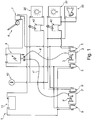
- FIG. 1 diagrammatically shows the coupling-releasing device for airbag actuator cable for motorcycles according to the present invention.
- the coupling-releasing device for airbag actuator cable 1 for motorcycles comprises at least one coupling unit 2, controlled by actuating means 4 and adapted to retain and release the airbag actuator cable in selective manner.
- the airbag is placed within a garment, typically a jacket, and an actuating cable connected to the airbag actuator ends with coupling means, typically a carabiner or the like.
- the airbag actuator cable and the coupling means of said cable are not part of the present invention.
- the diagram in figure 1 shows a configuration of the device according to the present invention which comprises two coupling units, a first coupling unit 2 and a second coupling unit 2' (the present invention is not limited to the presence of one or two coupling units).
- One coupling unit may be positioned on the vehicle so as to be used by the driver, while the second unit will be advantageously positioned on the vehicle so as to be used by the passenger.
- Each coupling unit 2, 2' may advantageously comprise a supporting block and at least one moveable hook, preferably as shown in the diagram in figure 1 , a pair of moveable hooks, 3 and 3' respectively, counterpoised and hinged so that the ends of each pair 3, 3' of said hooks may move reciprocally close or away, as diagrammatically shown in the drawing in figure 1 .
- said coupling unit can retain the coupling means of said airbag actuator cable, while when the moveable hooks 3, 3' of one coupling unit 2, 2' are in reciprocally distanced position, said coupling unit is in an open configuration at which the coupling means of the cable are released.
- the device further comprises actuator means 4, 4', 4", which advantageously comprise an electric actuator 4 operatively connected by means of a wire 4', 4" or other equivalent system adapted to exert a traction on the hooks of said coupling unit 2, 2'.
- actuator means 4, 4', 4" which advantageously comprise an electric actuator 4 operatively connected by means of a wire 4', 4" or other equivalent system adapted to exert a traction on the hooks of said coupling unit 2, 2'.
- each coupling unit 2, 2' comprises a pair of moveable hooks 3, 3', which are hinged to the supporting block and kept in the closing position by a contrast spring.
- Said electric actuator 4, comprising, for example, a piston having a given stroke, can pull the wire 4, 4', which exerts a traction force on said moveable hooks 3, which rotate, moving reciprocally away and positioning themselves in the opening position of the coupling unit.
- said coupling units 2, 2' further comprise closing means of the moveable hooks 3, 3', which cause the moveable hooks 3, 3' to snap closed when an end of the airbag cable is inserted in the coupling unit, as known in the prior art for the locks commonly used, for example to lock the saddle of motoscooters.
- said coupling-releasing device 1 for airbag actuating cable comprises a second micro switch 7 operatively connected to said electric motor 4, to said parking lever 6 and to at least one of the first micro switches 5, 5' operatively connected to said coupling unit 2.
- the described circuit allows the device 1 according to the present invention to operate said coupling units 2, 2' as a function of the position of the parking lever 6. More specifically, according to the diagram in figure 1 , when the parking lever 6 is placed in the position corresponding to the locking of the tilting system of the vehicle, the second micro switch 7 is closed, thus sending an electric signal to said actuator means 4, 4', 4" which determine the opening by means of said first micro switches 5, 5', of said coupling units 2, 2'.
- the device according to the present invention as described hereto may be advantageously connected to other parking means, such as the side or center stand of the vehicle.
- the second micro switch 7 will be operatively connected to said stand instead of the lever 6 shown in the diagram.
- the second micro switch 7 detects the stand down condition and sends an electric signal to the actuating means 4, 4', 4" to determine the automatic opening of the coupling units 2, 2' so that the airbag cable coupling means are freed and the cable is released from the vehicle in automatic manner without the user needing to perform any other action.
- an electric device (not shown in the diagram in figure 1 ) automatically reactivates the alarms when the cable is coupled into a coupling-releasing unit again, so as to reset the possible exclusion settings of the alarms operated manually by the user in automatic manner.
- the device may advantageously release the cable in automatic manner as soon as the engine is stopped, by means of an operating connection to the ignition key block.
- the device according to the present invention used either on vehicles with two or more wheels (and thus operatively connected to the parking lever), or on two-wheel vehicles (and thus operatively connected to the stand), may advantageously include further signaling means 20, 20', 30 of the operating condition of one or more said coupling units 2, 2'.
- said signaling means of the operating condition of the coupling unit may comprise visual signals and auditory signals.
- said signaling means comprise a first working light 20 adapted to signal the operating condition of the unit of the first coupling unit 2 intended to be engaged by the driver, and a second warning light 20' adapted to signal the operating condition of the second coupling unit 2' intended to be used by the passenger.
- Said signaling means may further comprise auditory alarms, in particular an auditory alarm 30 adapted to signal the operating condition of one or both coupling units 2, 2' in auditory manner.
- said auditory alarm 30 is adapted to signal the operating condition of the driver's coupling unit 2.
- said signaling means 20, 20', 30 are advantageously connected to the ignition key block 40 of the vehicle, in addition to the first micro switches 5, 5' operatively associated with said first 2 and second 2' coupling unit.
- the operation of the signaling means 20, 20', 30 is thus subordinated to the activation of the ignition key by the user: when the user turns the key to start the vehicle, even before the engine starts, but simply by powering the dashboard, the signaling means 20, 20', 30 receive current and are capable of detecting, by means of the first micro switches 5, 5', the operating condition of the coupling unit. If the user has not yet inserted the airbag cable coupling means of the coupling unit causing the mechanical closing, the signaling means 20, 20', 30 signal the uncoupled condition to the driver, by lighting the warning light 20, 20' on the dashboard and if present with the activation of the auditory signal 30.
- switches 40, 40' may be provided which may be actuated manually by the user and operatively associated with said signaling means 20, 20', 30.
- a first switch 40 may be associated with said first warning light 20 adapted to signal the operating condition of the first coupling unit 2 used by the driver, and a second switch 40' may be associated with said second warning light 20' adapted to signal the operating condition of the second coupling unit 2'.
- the first warning light 20 may be also associated with said auditory signaling means 30.
- the user may manually deactivate the visual and auditory alarms which signal the no airbag cable coupling condition to the coupling units 2, 2'.
- the user may decide, for example, to deactivate the signaling means of the operating condition associated with the second coupling unit (the passenger's) if the driver is traveling alone, or may deactivate the signaling means associated with the driver's own coupling unit 2 to use the vehicle without wearing the jacket provided with airbag, the signaling means being reactivated automatically when the cable is coupled again and remain operative until the driver decides to deactivate them again.
- the coupling and releasing units 2, 2' may be operated directly from the ignition key block 40 by means of the actuator 4: in this manner, the releasing and coupling units 2, 2' open automatically when the user turns the key to the off position.
Landscapes
- Engineering & Computer Science (AREA)
- Mechanical Engineering (AREA)
- Health & Medical Sciences (AREA)
- General Health & Medical Sciences (AREA)
- Physical Education & Sports Medicine (AREA)
- Textile Engineering (AREA)
- Air Bags (AREA)
- Professional, Industrial, Or Sporting Protective Garments (AREA)
Description
- The present invention relates to a coupling-releasing device for airbag actuator cable for vehicles having two or more wheels, said airbag being contained in a wearable jacket or coat.
- More in particular, the coupling-releasing device for airbag actuator cable according to the present invention also applies to motoscooters with two or more wheels, e.g. motoscooters with three or more wheels and at least two tilting wheels, in addition to two-wheel motorcycles.
- Active and passive safety in the motorcycle field is increasingly more felt and has made enormous progress lately, to the extent that many innovations which were once prohibitively expensive are now widely common because the cost of such technologies is now sufficiently low. Some examples include brake anti-locking systems (ABS), electronic control suspensions, highly ergonomic leather suits with protections made of specifically designed materials, and so on.
- In these technologies, full face helmets, protections and airbags for motorcycles in general have enormously contributed to improving passive safety.
- The object of the present invention relates to an airbag for motorcycles, in particular to a coupling and releasing device of the actuating cable of a mechanically actuated airbag contained in a garment.
- It is also known that mechanically actuated and electronically actuated airbags exist in the motorcycle field.
- Mechanically actuated airbags comprise one or more bags folded inside a wearable jacket which are inflated with gas when required after having pulled a cable with a traction force beyond a predetermined threshold value.
- The jacket provided with airbag is thus provided with a specific cable which must be secured to the motorcycle by the user; in case of accident, the rider falls and moves away from the motorcycle, the cable will be pulled and will fire the inflatable protection device, which fully inflates in approximately 80 thousands of a second.
- System operation is thus simple and now well tested, however it is not very popular on the market, and this is because the users find annoying having a cable which ties them to the motorcycle. Motorcyclists have the impression of being restricted in their movements but above all fear to forget the cable connected to the vehicle when they want to get off, thus causing an involuntary, undesired firing of the airbag, with the evident consequences also in terms of time needed to restore the airbag and of costs for recharging the airbag gas, in addition to the annoyance caused by the temporary unavailability of the jacket and its protection.
- Electronically actuated airbags which do not require the traction of a cable to be fired have thus appear on the market: in this type of device, the airbag is electronically actuated by a dedicated system.Obviously, in this case, the system requires the use of accelerometers, batteries for storing electricity and other components, which, in addition to further increasing the weight of the jacket, also increase its costs; the batteries have the drawback of needing to be periodically recharged, thus limiting the possibility to use the jacket by users if they forget to recharge the batteries before the next use.
- Consequently, for the reasons illustrated above, electronically actuated airbags are not very common because of their cost and the need to keep them in the correct operating condition, whereas mechanically actuated airbags are seldom used because of the need to have a cable connecting the airbag jacket to the vehicle, which is perceived as an obstacle to freedom of movements, particularly when getting on and getting off the vehicle: indeed, the user must remember to release a carabiner, which connects the airbag actuating cable to a dedicated ring integral with the vehicle, manually.
- The known type configuration includes no interaction between vehicle and airbag, nor between vehicle and airbag actuating cable: no system is provided to notify the airbag actuator cable condition (whether it is connected to the vehicle or not), and thus the airbag operating condition, to the user.
- Therefore, the known type configuration does not allow users to know whether the actuator cable is correctly connected to the vehicle when they get on and prepare to drive off, nor does it allow users to disconnect automatically when getting off the vehicle, thus preventing the accidental firing of the airbag.
- Examples of coupling releasing devices for airbag actuator cables for vehicles are known from
EP 2673184 andUS 2008/178370 . - A coupling-releasing device for an airbag actuator cable for a vehicle with two or more wheels according to the preamble of independent claim 1 is known from
JP 2010 070112 - It is the main task of the present invention to provide an airbag actuator cable coupling and releasing device for vehicles having two or more wheels adapted to solve the drawbacks which afflict systems of the known type.
- More specifically, the device according to the present invention in accordance with claim 1 allows the user to know the coupling condition of the airbag actuating cable to the vehicle at all times, thus avoiding undesired airbag actuation.
- Indeed, a frequent condition is the one in which the user having stopped the vehicle decides to get off and forgets to disconnect the airbag cable from the vehicle, thus causing an accidental deployment of the airbag.
- The device according to the present invention allows to solve this drawback because it provides specific automatic releasing system of the airbag cable from the vehicle when the vehicle is stationary and the user is about to get off.
- Advantageously, the device according to the present invention can detect the connected/not connected condition of the actuation cable for the driver's airbag and the passenger's airbag.
- Further features are described in the dependent claims.
- Further objects and advantages of the present invention will be apparent in the detailed description of an embodiment shown by way of non-limiting example in the accompanying
figure 1 , which diagrammatically shows the coupling-releasing device for airbag actuator cable for motorcycles according to the present invention. - According to a preferred embodiment according to the present invention illustrated hereby way of non-limiting example, the coupling-releasing device for airbag actuator cable 1 for motorcycles comprises at least one coupling unit 2, controlled by actuating
means 4 and adapted to retain and release the airbag actuator cable in selective manner. In general, as known in the prior art, the airbag is placed within a garment, typically a jacket, and an actuating cable connected to the airbag actuator ends with coupling means, typically a carabiner or the like. The airbag actuator cable and the coupling means of said cable are not part of the present invention. - Hereinafter, the diagram in
figure 1 shows a configuration of the device according to the present invention which comprises two coupling units, a first coupling unit 2 and a second coupling unit 2' (the present invention is not limited to the presence of one or two coupling units). One coupling unit may be positioned on the vehicle so as to be used by the driver, while the second unit will be advantageously positioned on the vehicle so as to be used by the passenger. - Each coupling unit 2, 2' may advantageously comprise a supporting block and at least one moveable hook, preferably as shown in the diagram in
figure 1 , a pair of moveable hooks, 3 and 3' respectively, counterpoised and hinged so that the ends of each pair 3, 3' of said hooks may move reciprocally close or away, as diagrammatically shown in the drawing infigure 1 . When the moveable hooks 3, 3' of one of said coupling units 2, 2' are in the reciprocally approached position, said coupling unit can retain the coupling means of said airbag actuator cable, while when the moveable hooks 3, 3' of one coupling unit 2, 2' are in reciprocally distanced position, said coupling unit is in an open configuration at which the coupling means of the cable are released. - As mentioned, the device further comprises actuator means 4, 4', 4", which advantageously comprise an
electric actuator 4 operatively connected by means of awire 4', 4" or other equivalent system adapted to exert a traction on the hooks of said coupling unit 2, 2'. - More in detail, in the preferred embodiment of the device 1 according to the present invention, each coupling unit 2, 2' comprises a pair of moveable hooks 3, 3', which are hinged to the supporting block and kept in the closing position by a contrast spring. Said
electric actuator 4, comprising, for example, a piston having a given stroke, can pull thewire 4, 4', which exerts a traction force on said moveable hooks 3, which rotate, moving reciprocally away and positioning themselves in the opening position of the coupling unit. - Advantageously, said coupling units 2, 2' further comprise closing means of the moveable hooks 3, 3', which cause the moveable hooks 3, 3' to snap closed when an end of the airbag cable is inserted in the coupling unit, as known in the prior art for the locks commonly used, for example to lock the saddle of motoscooters.
- In general, in the case of vehicles with three or four wheels, of which at least two tilting, parking means are provided, in particular a parking lever or tiling system lock is provided. When wanting to get off the vehicle, the user must necessarily apply the lock to prevent the vehicle from inclining and falling to the ground. In a preferred embodiment of the present invention, in which the device is applied to vehicles with two or more wheels, said coupling-releasing device 1 for airbag actuating cable comprises a second micro switch 7 operatively connected to said
electric motor 4, to said parking lever 6 and to at least one of the first micro switches 5, 5' operatively connected to said coupling unit 2. - The described circuit allows the device 1 according to the present invention to operate said coupling units 2, 2' as a function of the position of the parking lever 6. More specifically, according to the diagram in
figure 1 , when the parking lever 6 is placed in the position corresponding to the locking of the tilting system of the vehicle, the second micro switch 7 is closed, thus sending an electric signal to said actuator means 4, 4', 4" which determine the opening by means of said first micro switches 5, 5', of said coupling units 2, 2'. - In traditional two-wheel motorcycles, in which there is no parking lever or tilting system lock, the device according to the present invention as described hereto may be advantageously connected to other parking means, such as the side or center stand of the vehicle. In particular, with reference to the diagram in
figure 1 , the second micro switch 7 will be operatively connected to said stand instead of the lever 6 shown in the diagram. - The operation of the device is the same as illustrated hereto: when the user parks the vehicle and operates the side or center stand to get off and move away from the vehicle, the second micro switch 7 detects the stand down condition and sends an electric signal to the actuating means 4, 4', 4" to determine the automatic opening of the coupling units 2, 2' so that the airbag cable coupling means are freed and the cable is released from the vehicle in automatic manner without the user needing to perform any other action.
- Preferably, an electric device (not shown in the diagram in
figure 1 ) automatically reactivates the alarms when the cable is coupled into a coupling-releasing unit again, so as to reset the possible exclusion settings of the alarms operated manually by the user in automatic manner. - In an alternative embodiment with respect to the one shown in
figure 1 , the device may advantageously release the cable in automatic manner as soon as the engine is stopped, by means of an operating connection to the ignition key block. - Again with reference to the diagram in
figure 1 , the device according to the present invention, used either on vehicles with two or more wheels (and thus operatively connected to the parking lever), or on two-wheel vehicles (and thus operatively connected to the stand), may advantageously include further signaling means 20, 20', 30 of the operating condition of one or more said coupling units 2, 2'. - More specifically, said signaling means of the operating condition of the coupling unit may comprise visual signals and auditory signals. Advantageously, said signaling means comprise a first working
light 20 adapted to signal the operating condition of the unit of the first coupling unit 2 intended to be engaged by the driver, and a second warning light 20' adapted to signal the operating condition of the second coupling unit 2' intended to be used by the passenger. Said signaling means may further comprise auditory alarms, in particular an auditory alarm 30 adapted to signal the operating condition of one or both coupling units 2, 2' in auditory manner. - Preferably, said auditory alarm 30 is adapted to signal the operating condition of the driver's coupling unit 2.
- According to a preferred embodiment of the device according to the present invention shown in
figure 1 , said signaling means 20, 20', 30 are advantageously connected to theignition key block 40 of the vehicle, in addition to the first micro switches 5, 5' operatively associated with said first 2 and second 2' coupling unit. - The operation of the signaling means 20, 20', 30 is thus subordinated to the activation of the ignition key by the user: when the user turns the key to start the vehicle, even before the engine starts, but simply by powering the dashboard, the signaling means 20, 20', 30 receive current and are capable of detecting, by means of the first micro switches 5, 5', the operating condition of the coupling unit. If the user has not yet inserted the airbag cable coupling means of the coupling unit causing the mechanical closing, the signaling means 20, 20', 30 signal the uncoupled condition to the driver, by lighting the
warning light 20, 20' on the dashboard and if present with the activation of the auditory signal 30. - When the user inserts the end of the airbag cable provided with coupling means in one of the two coupling units 2, 2', the closing condition of the moveable hooks 3, 3' is detected by the first micro switches 5, 5' and the corresponding signaling means are deactivated.
- Advantageously, further
switches 40, 40' may be provided which may be actuated manually by the user and operatively associated with said signaling means 20, 20', 30. - More in detail, a
first switch 40 may be associated with saidfirst warning light 20 adapted to signal the operating condition of the first coupling unit 2 used by the driver, and a second switch 40' may be associated with said second warning light 20' adapted to signal the operating condition of the second coupling unit 2'. Possibly, one of the two warning lights, according to the diagram infigure 1 , thefirst warning light 20 may be also associated with said auditory signaling means 30. - By means of said switches, the user may manually deactivate the visual and auditory alarms which signal the no airbag cable coupling condition to the coupling units 2, 2'. By means of this function, the user may decide, for example, to deactivate the signaling means of the operating condition associated with the second coupling unit (the passenger's) if the driver is traveling alone, or may deactivate the signaling means associated with the driver's own coupling unit 2 to use the vehicle without wearing the jacket provided with airbag, the signaling means being reactivated automatically when the cable is coupled again and remain operative until the driver decides to deactivate them again.
- According to an alternative embodiment of the device according the present invention, the coupling and releasing units 2, 2' may be operated directly from the
ignition key block 40 by means of the actuator 4: in this manner, the releasing and coupling units 2, 2' open automatically when the user turns the key to the off position. - Many changes, modifications, variations and other uses and applications of the subject invention will be apparent to a person skilled in the art after having considered the description and the accompanying drawings which illustrate preferred embodiments thereof. Such changes, modifications, variations and other uses and applications which do not differ from the scope of the invention as defined in the appended claims and form an integral part of the text are covered by the present invention.
Claims (10)
- A coupling-releasing device (1) for an airbag actuator cable for a vehicles with two or more wheels, comprising at least one coupling unit (2, 2') adapted to be installed on board a of the vehicle, said at least one coupling unit (2, 2') being operable between a closed configuration for retaining an end of the airbag actuator cable and an open configuration for releasing said end of the airbag actuator cable,
characterized in that it further comprises
at least one electric actuator (4) operatively connected to said at least one coupling unit (2, 2') to operate said at least one coupling unit (2, 2') between said closed configuration and said open configuration, and
at least one micro switch (7) which is adapted to detect the position of parking means of the vehicle and is configured to send an electric signal to said at least one electric actuator (4) to operate said at least one coupling unit (2, 2') from said closed configuration to said open configuration when a parked condition of the vehicle is detected by said at least one micro switch (7). - A device (1) according to claim 1, wherein said at least one coupling unit (2, 2') comprises at least one supporting block adapted to be installed on board a of the vehicle and at least one hook (3, 3') moveable between a closed position adapted to retain said end of the airbag actuator cable and an open position adapted to release said end of the airbag actuator cable.
- A device (1) according to claim 2, wherein said at least one moveable hook (3, 3') is provided with closing means adapted to take said at least one moveable hook (3, 3') to the closed position in automatic manner when said end of the airbag actuator cable is inserted by the user into said at least one coupling unit (2, 2').
- A device (1) according to claim 3, wherein each of said at least one coupling units (2, 2') comprises a pair of counterpoised moveable hooks (3, 3') hinged so that the ends of each pair of said hooks (3, 3') are moveable reciprocally towards and away from each other, and wherein said closing means comprise a contrast spring for maintaining said pair of hooks (3, 3') in said closed position.
- A device (1) according to claim 4, wherein said at least one electric actuator (4) is connected by means of at least one wire (4, 4') to said moveable hooks (3, 3') and is configured to exert a traction force sufficient to overcome the action of said contrast spring on said hooks (3, 3'), thus taking said hooks (3, 3') to the open position.
- A device (1) according to one or more of the preceding claims, wherein it further comprises signalling means (20, 20', 30) for signalling the operating condition of said at least one coupling unit (2, 2').
- A device (1) according to one or more of the preceding claims, wherein said signalling means comprise visual signals (20, 20') and auditory signals (30).
- A device (1) according to one or more of the preceding claims, comprising a first coupling unit (2) intended to be used by the driver and a second coupling unit (2') intended to be used by the passenger.
- A device (1) according to one or more of the preceding claims, wherein said signalling means are operatively connected to the ignition key block (40) of the vehicle.
- A device (1) according to one or more of the preceding claims, wherein said at least one electric actuator (4) is operatively connected to the ignition key block (40) of the vehicle.
Applications Claiming Priority (1)
| Application Number | Priority Date | Filing Date | Title |
|---|---|---|---|
| PCT/IB2014/065533 WO2016063109A1 (en) | 2014-10-22 | 2014-10-22 | Coupling-releasing device for airbag actuator cable for vehicles with two or more wheels |
Publications (3)
| Publication Number | Publication Date |
|---|---|
| EP3209542A1 EP3209542A1 (en) | 2017-08-30 |
| EP3209542B1 true EP3209542B1 (en) | 2020-06-24 |
| EP3209542B8 EP3209542B8 (en) | 2020-08-19 |
Family
ID=52011261
Family Applications (1)
| Application Number | Title | Priority Date | Filing Date |
|---|---|---|---|
| EP14808713.3A Active EP3209542B8 (en) | 2014-10-22 | 2014-10-22 | Coupling-releasing device for airbag actuator cable for vehicles with two or more wheels |
Country Status (10)
| Country | Link |
|---|---|
| US (1) | US10507778B2 (en) |
| EP (1) | EP3209542B8 (en) |
| JP (1) | JP6556230B2 (en) |
| CN (1) | CN107000667B (en) |
| AR (1) | AR102296A1 (en) |
| CA (1) | CA2964847A1 (en) |
| ES (1) | ES2817445T3 (en) |
| MX (1) | MX2017005275A (en) |
| TW (1) | TWI701173B (en) |
| WO (1) | WO2016063109A1 (en) |
Citations (1)
| Publication number | Priority date | Publication date | Assignee | Title |
|---|---|---|---|---|
| JP2010070112A (en) * | 2008-09-19 | 2010-04-02 | Honda Motor Co Ltd | Coupling mechanism of line member and airbag device |
Family Cites Families (19)
| Publication number | Priority date | Publication date | Assignee | Title |
|---|---|---|---|---|
| NL7905948A (en) * | 1979-08-02 | 1981-02-04 | Lassche Jakob | CLOSING DEVICE FOR A SEAT BELT. |
| DE3020505A1 (en) * | 1980-05-30 | 1981-12-10 | Daimler-Benz Ag, 7000 Stuttgart | RELEASABLE SENSOR THROUGH DELAY |
| DE3416594C2 (en) | 1984-05-04 | 1986-03-13 | Alexander Schoeller & Co AG, Volketswil, Schwerzenbach | Method for determining oxidation-dependent properties of similar plastic bodies and uses of the method and device for carrying out the method on large injection-molded parts, in particular bottle crates |
| DE3777948D1 (en) * | 1986-10-29 | 1992-05-07 | Hammerstein Gmbh C Rob | VEHICLE SEAT WITH A LENGTH GUIDE, WITH A HEIGHT OR ANGLE ADJUSTMENT AND WITH A BELT FASTENING. |
| JPH0966789A (en) * | 1995-08-31 | 1997-03-11 | Bridgestone Corp | Wearable airbag |
| DE19841750A1 (en) * | 1998-09-11 | 2000-03-16 | Bayerische Motoren Werke Ag | Seat belt system for a motor vehicle |
| JP2003312569A (en) * | 2002-04-23 | 2003-11-06 | Prop:Kk | Airbag device for human body |
| JP2004196176A (en) | 2002-12-19 | 2004-07-15 | Nissan Motor Co Ltd | Seat belt wearing promotion device |
| JP4458420B2 (en) * | 2004-09-29 | 2010-04-28 | 本田技研工業株式会社 | Crew restraint device |
| JP2006160171A (en) * | 2004-12-10 | 2006-06-22 | Honda Motor Co Ltd | Airbag device for vehicle |
| GB2427996A (en) * | 2005-07-08 | 2007-01-17 | Gerald Stretton | Safety system for a motorbike |
| JP4590331B2 (en) * | 2005-09-14 | 2010-12-01 | 本田技研工業株式会社 | Crew departure detection device |
| JP4627474B2 (en) * | 2005-09-30 | 2011-02-09 | 本田技研工業株式会社 | Airbag device |
| JP4679376B2 (en) * | 2006-01-25 | 2011-04-27 | タカタ株式会社 | Motorcycle airbag device, motorcycle |
| JP4931624B2 (en) * | 2007-01-31 | 2012-05-16 | 本田技研工業株式会社 | Air bag jacket |
| US20090013510A1 (en) | 2007-07-11 | 2009-01-15 | Feng Chia Liang | Buckle device |
| SG183578A1 (en) | 2011-02-10 | 2012-09-27 | Green 5 Holding Pte Ltd | A self-releasable safety belt |
| CN202190774U (en) | 2011-08-01 | 2012-04-18 | 吴钢芳 | Protective garment |
| US8783722B1 (en) * | 2013-01-02 | 2014-07-22 | Gerald F. Gallo | Self-releasing vehicular harness |
-
2014
- 2014-10-22 WO PCT/IB2014/065533 patent/WO2016063109A1/en not_active Ceased
- 2014-10-22 ES ES14808713T patent/ES2817445T3/en active Active
- 2014-10-22 CA CA2964847A patent/CA2964847A1/en not_active Abandoned
- 2014-10-22 EP EP14808713.3A patent/EP3209542B8/en active Active
- 2014-10-22 CN CN201480082789.8A patent/CN107000667B/en active Active
- 2014-10-22 US US15/519,483 patent/US10507778B2/en active Active
- 2014-10-22 JP JP2017521200A patent/JP6556230B2/en not_active Expired - Fee Related
- 2014-10-22 MX MX2017005275A patent/MX2017005275A/en unknown
-
2015
- 2015-10-07 TW TW104132993A patent/TWI701173B/en active
- 2015-10-16 AR ARP150103354A patent/AR102296A1/en unknown
Patent Citations (1)
| Publication number | Priority date | Publication date | Assignee | Title |
|---|---|---|---|---|
| JP2010070112A (en) * | 2008-09-19 | 2010-04-02 | Honda Motor Co Ltd | Coupling mechanism of line member and airbag device |
Also Published As
| Publication number | Publication date |
|---|---|
| JP6556230B2 (en) | 2019-08-07 |
| CN107000667B (en) | 2019-11-12 |
| WO2016063109A1 (en) | 2016-04-28 |
| AR102296A1 (en) | 2017-02-15 |
| MX2017005275A (en) | 2018-01-09 |
| US10507778B2 (en) | 2019-12-17 |
| TWI701173B (en) | 2020-08-11 |
| TW201617253A (en) | 2016-05-16 |
| US20170240129A1 (en) | 2017-08-24 |
| EP3209542B8 (en) | 2020-08-19 |
| JP2017532249A (en) | 2017-11-02 |
| EP3209542A1 (en) | 2017-08-30 |
| CA2964847A1 (en) | 2016-04-28 |
| ES2817445T3 (en) | 2021-04-07 |
| CN107000667A (en) | 2017-08-01 |
Similar Documents
| Publication | Publication Date | Title |
|---|---|---|
| EP2844515B1 (en) | Vehicle security | |
| US9352729B2 (en) | Remote control system and method for parking brake of vehicle | |
| JPH1076911A (en) | Vehicle safety device with removable seat, especially passenger seat | |
| US5816611A (en) | Arrangement for disconnecting a vehicle airbag | |
| ES3030860T3 (en) | Child safety seat alarm system | |
| AU2018275781B2 (en) | Remote lighting system operable to correspond with vehicle lighting | |
| EP1668999A1 (en) | Airbag apparatus for a vehicle passenger | |
| WO2017153013A1 (en) | Dismountable seat | |
| GB2501726A (en) | Vehicle security during charging of an electric or hybrid vehicle | |
| US10507778B2 (en) | Coupling-releasing device for airbag actuator cable for vehicles with two or more wheels | |
| US20060191730A1 (en) | Vehicular safety system including automated cruise control disengagement and warning signals | |
| EP2733021B1 (en) | A passenger airbag switch | |
| CN100581880C (en) | Self-locking safety air sac of strap | |
| EP2839997A1 (en) | Arrangement for control of vehicle seat belt alert arrangement, a seat, a vehicle, a method and use of the arrangement | |
| KR101875365B1 (en) | Alarm device for checking states of vehicle side brake | |
| GB2461200A (en) | Motorcycle warning system activated by inboard movement of a hand or arm along a handlebar | |
| US8444178B2 (en) | Airbag apparatus | |
| KR100827732B1 (en) | Seat belt fastener | |
| KR20090002510A (en) | Rear bumper air pack | |
| JP2015077955A (en) | Human body restraining device | |
| KR19980030140U (en) | Vehicle Multi Collision Hazard Warning Device | |
| KR20140001437U (en) | Apparatus for preventing of sleepiness | |
| TWM412896U (en) | Car driving safety device | |
| JPH0829697B2 (en) | Malfunction prevention device for air bag modules in automobiles |
Legal Events
| Date | Code | Title | Description |
|---|---|---|---|
| STAA | Information on the status of an ep patent application or granted ep patent |
Free format text: STATUS: THE INTERNATIONAL PUBLICATION HAS BEEN MADE |
|
| PUAI | Public reference made under article 153(3) epc to a published international application that has entered the european phase |
Free format text: ORIGINAL CODE: 0009012 |
|
| STAA | Information on the status of an ep patent application or granted ep patent |
Free format text: STATUS: REQUEST FOR EXAMINATION WAS MADE |
|
| 17P | Request for examination filed |
Effective date: 20170519 |
|
| AK | Designated contracting states |
Kind code of ref document: A1 Designated state(s): AL AT BE BG CH CY CZ DE DK EE ES FI FR GB GR HR HU IE IS IT LI LT LU LV MC MK MT NL NO PL PT RO RS SE SI SK SM TR |
|
| AX | Request for extension of the european patent |
Extension state: BA ME |
|
| RIN1 | Information on inventor provided before grant (corrected) |
Inventor name: MARABESE, RICCARDO Inventor name: MORONI, MARCO |
|
| DAX | Request for extension of the european patent (deleted) | ||
| STAA | Information on the status of an ep patent application or granted ep patent |
Free format text: STATUS: EXAMINATION IS IN PROGRESS |
|
| 17Q | First examination report despatched |
Effective date: 20190517 |
|
| GRAP | Despatch of communication of intention to grant a patent |
Free format text: ORIGINAL CODE: EPIDOSNIGR1 |
|
| STAA | Information on the status of an ep patent application or granted ep patent |
Free format text: STATUS: GRANT OF PATENT IS INTENDED |
|
| INTG | Intention to grant announced |
Effective date: 20191213 |
|
| GRAS | Grant fee paid |
Free format text: ORIGINAL CODE: EPIDOSNIGR3 |
|
| GRAA | (expected) grant |
Free format text: ORIGINAL CODE: 0009210 |
|
| STAA | Information on the status of an ep patent application or granted ep patent |
Free format text: STATUS: THE PATENT HAS BEEN GRANTED |
|
| RIN1 | Information on inventor provided before grant (corrected) |
Inventor name: MARABESE, RICCARDO Inventor name: MORONI, MARCO |
|
| AK | Designated contracting states |
Kind code of ref document: B1 Designated state(s): AL AT BE BG CH CY CZ DE DK EE ES FI FR GB GR HR HU IE IS IT LI LT LU LV MC MK MT NL NO PL PT RO RS SE SI SK SM TR |
|
| RAP1 | Party data changed (applicant data changed or rights of an application transferred) |
Owner name: QOODER SA |
|
| REG | Reference to a national code |
Ref country code: GB Ref legal event code: FG4D |
|
| REG | Reference to a national code |
Ref country code: CH Ref legal event code: EP Ref country code: CH Ref legal event code: PK Free format text: BERICHTIGUNGEN |
|
| GRAT | Correction requested after decision to grant or after decision to maintain patent in amended form |
Free format text: ORIGINAL CODE: EPIDOSNCDEC |
|
| REG | Reference to a national code |
Ref country code: AT Ref legal event code: REF Ref document number: 1283625 Country of ref document: AT Kind code of ref document: T Effective date: 20200715 |
|
| REG | Reference to a national code |
Ref country code: DE Ref legal event code: R096 Ref document number: 602014067051 Country of ref document: DE |
|
| REG | Reference to a national code |
Ref country code: IE Ref legal event code: FG4D |
|
| RIN2 | Information on inventor provided after grant (corrected) |
Inventor name: MARABESE, RICCARDO Inventor name: MORONI, MARCO |
|
| REG | Reference to a national code |
Ref country code: CH Ref legal event code: PK Free format text: BERICHTIGUNGEN Ref country code: CH Ref legal event code: PK Free format text: BERICHTIGUNG B8 |
|
| RIN2 | Information on inventor provided after grant (corrected) |
Inventor name: MARABESE, RICCARDO Inventor name: MORONI, MARCO |
|
| REG | Reference to a national code |
Ref country code: CH Ref legal event code: NV Representative=s name: VALIPAT S.A. C/O BOVARD SA NEUCHATEL, CH |
|
| PG25 | Lapsed in a contracting state [announced via postgrant information from national office to epo] |
Ref country code: LT Free format text: LAPSE BECAUSE OF FAILURE TO SUBMIT A TRANSLATION OF THE DESCRIPTION OR TO PAY THE FEE WITHIN THE PRESCRIBED TIME-LIMIT Effective date: 20200624 Ref country code: SE Free format text: LAPSE BECAUSE OF FAILURE TO SUBMIT A TRANSLATION OF THE DESCRIPTION OR TO PAY THE FEE WITHIN THE PRESCRIBED TIME-LIMIT Effective date: 20200624 Ref country code: NO Free format text: LAPSE BECAUSE OF FAILURE TO SUBMIT A TRANSLATION OF THE DESCRIPTION OR TO PAY THE FEE WITHIN THE PRESCRIBED TIME-LIMIT Effective date: 20200924 Ref country code: GR Free format text: LAPSE BECAUSE OF FAILURE TO SUBMIT A TRANSLATION OF THE DESCRIPTION OR TO PAY THE FEE WITHIN THE PRESCRIBED TIME-LIMIT Effective date: 20200925 Ref country code: FI Free format text: LAPSE BECAUSE OF FAILURE TO SUBMIT A TRANSLATION OF THE DESCRIPTION OR TO PAY THE FEE WITHIN THE PRESCRIBED TIME-LIMIT Effective date: 20200624 |
|
| REG | Reference to a national code |
Ref country code: LT Ref legal event code: MG4D |
|
| PG25 | Lapsed in a contracting state [announced via postgrant information from national office to epo] |
Ref country code: LV Free format text: LAPSE BECAUSE OF FAILURE TO SUBMIT A TRANSLATION OF THE DESCRIPTION OR TO PAY THE FEE WITHIN THE PRESCRIBED TIME-LIMIT Effective date: 20200624 Ref country code: HR Free format text: LAPSE BECAUSE OF FAILURE TO SUBMIT A TRANSLATION OF THE DESCRIPTION OR TO PAY THE FEE WITHIN THE PRESCRIBED TIME-LIMIT Effective date: 20200624 Ref country code: RS Free format text: LAPSE BECAUSE OF FAILURE TO SUBMIT A TRANSLATION OF THE DESCRIPTION OR TO PAY THE FEE WITHIN THE PRESCRIBED TIME-LIMIT Effective date: 20200624 Ref country code: BG Free format text: LAPSE BECAUSE OF FAILURE TO SUBMIT A TRANSLATION OF THE DESCRIPTION OR TO PAY THE FEE WITHIN THE PRESCRIBED TIME-LIMIT Effective date: 20200924 |
|
| REG | Reference to a national code |
Ref country code: NL Ref legal event code: MP Effective date: 20200624 |
|
| REG | Reference to a national code |
Ref country code: AT Ref legal event code: MK05 Ref document number: 1283625 Country of ref document: AT Kind code of ref document: T Effective date: 20200624 |
|
| PG25 | Lapsed in a contracting state [announced via postgrant information from national office to epo] |
Ref country code: NL Free format text: LAPSE BECAUSE OF FAILURE TO SUBMIT A TRANSLATION OF THE DESCRIPTION OR TO PAY THE FEE WITHIN THE PRESCRIBED TIME-LIMIT Effective date: 20200624 Ref country code: AL Free format text: LAPSE BECAUSE OF FAILURE TO SUBMIT A TRANSLATION OF THE DESCRIPTION OR TO PAY THE FEE WITHIN THE PRESCRIBED TIME-LIMIT Effective date: 20200624 |
|
| PG25 | Lapsed in a contracting state [announced via postgrant information from national office to epo] |
Ref country code: CZ Free format text: LAPSE BECAUSE OF FAILURE TO SUBMIT A TRANSLATION OF THE DESCRIPTION OR TO PAY THE FEE WITHIN THE PRESCRIBED TIME-LIMIT Effective date: 20200624 Ref country code: RO Free format text: LAPSE BECAUSE OF FAILURE TO SUBMIT A TRANSLATION OF THE DESCRIPTION OR TO PAY THE FEE WITHIN THE PRESCRIBED TIME-LIMIT Effective date: 20200624 Ref country code: PT Free format text: LAPSE BECAUSE OF FAILURE TO SUBMIT A TRANSLATION OF THE DESCRIPTION OR TO PAY THE FEE WITHIN THE PRESCRIBED TIME-LIMIT Effective date: 20201026 Ref country code: AT Free format text: LAPSE BECAUSE OF FAILURE TO SUBMIT A TRANSLATION OF THE DESCRIPTION OR TO PAY THE FEE WITHIN THE PRESCRIBED TIME-LIMIT Effective date: 20200624 Ref country code: SM Free format text: LAPSE BECAUSE OF FAILURE TO SUBMIT A TRANSLATION OF THE DESCRIPTION OR TO PAY THE FEE WITHIN THE PRESCRIBED TIME-LIMIT Effective date: 20200624 Ref country code: EE Free format text: LAPSE BECAUSE OF FAILURE TO SUBMIT A TRANSLATION OF THE DESCRIPTION OR TO PAY THE FEE WITHIN THE PRESCRIBED TIME-LIMIT Effective date: 20200624 |
|
| PGFP | Annual fee paid to national office [announced via postgrant information from national office to epo] |
Ref country code: CH Payment date: 20201021 Year of fee payment: 7 |
|
| PG25 | Lapsed in a contracting state [announced via postgrant information from national office to epo] |
Ref country code: PL Free format text: LAPSE BECAUSE OF FAILURE TO SUBMIT A TRANSLATION OF THE DESCRIPTION OR TO PAY THE FEE WITHIN THE PRESCRIBED TIME-LIMIT Effective date: 20200624 Ref country code: SK Free format text: LAPSE BECAUSE OF FAILURE TO SUBMIT A TRANSLATION OF THE DESCRIPTION OR TO PAY THE FEE WITHIN THE PRESCRIBED TIME-LIMIT Effective date: 20200624 Ref country code: IS Free format text: LAPSE BECAUSE OF FAILURE TO SUBMIT A TRANSLATION OF THE DESCRIPTION OR TO PAY THE FEE WITHIN THE PRESCRIBED TIME-LIMIT Effective date: 20201024 |
|
| REG | Reference to a national code |
Ref country code: DE Ref legal event code: R097 Ref document number: 602014067051 Country of ref document: DE |
|
| REG | Reference to a national code |
Ref country code: ES Ref legal event code: FG2A Ref document number: 2817445 Country of ref document: ES Kind code of ref document: T3 Effective date: 20210407 |
|
| PG25 | Lapsed in a contracting state [announced via postgrant information from national office to epo] |
Ref country code: DK Free format text: LAPSE BECAUSE OF FAILURE TO SUBMIT A TRANSLATION OF THE DESCRIPTION OR TO PAY THE FEE WITHIN THE PRESCRIBED TIME-LIMIT Effective date: 20200624 |
|
| PLBE | No opposition filed within time limit |
Free format text: ORIGINAL CODE: 0009261 |
|
| STAA | Information on the status of an ep patent application or granted ep patent |
Free format text: STATUS: NO OPPOSITION FILED WITHIN TIME LIMIT |
|
| 26N | No opposition filed |
Effective date: 20210325 |
|
| PG25 | Lapsed in a contracting state [announced via postgrant information from national office to epo] |
Ref country code: LU Free format text: LAPSE BECAUSE OF NON-PAYMENT OF DUE FEES Effective date: 20201022 Ref country code: MC Free format text: LAPSE BECAUSE OF FAILURE TO SUBMIT A TRANSLATION OF THE DESCRIPTION OR TO PAY THE FEE WITHIN THE PRESCRIBED TIME-LIMIT Effective date: 20200624 |
|
| REG | Reference to a national code |
Ref country code: BE Ref legal event code: MM Effective date: 20201031 |
|
| PG25 | Lapsed in a contracting state [announced via postgrant information from national office to epo] |
Ref country code: BE Free format text: LAPSE BECAUSE OF NON-PAYMENT OF DUE FEES Effective date: 20201031 Ref country code: SI Free format text: LAPSE BECAUSE OF FAILURE TO SUBMIT A TRANSLATION OF THE DESCRIPTION OR TO PAY THE FEE WITHIN THE PRESCRIBED TIME-LIMIT Effective date: 20200624 |
|
| PG25 | Lapsed in a contracting state [announced via postgrant information from national office to epo] |
Ref country code: IE Free format text: LAPSE BECAUSE OF NON-PAYMENT OF DUE FEES Effective date: 20201022 |
|
| REG | Reference to a national code |
Ref country code: CH Ref legal event code: PL |
|
| PG25 | Lapsed in a contracting state [announced via postgrant information from national office to epo] |
Ref country code: TR Free format text: LAPSE BECAUSE OF FAILURE TO SUBMIT A TRANSLATION OF THE DESCRIPTION OR TO PAY THE FEE WITHIN THE PRESCRIBED TIME-LIMIT Effective date: 20200624 Ref country code: MT Free format text: LAPSE BECAUSE OF FAILURE TO SUBMIT A TRANSLATION OF THE DESCRIPTION OR TO PAY THE FEE WITHIN THE PRESCRIBED TIME-LIMIT Effective date: 20200624 Ref country code: CY Free format text: LAPSE BECAUSE OF FAILURE TO SUBMIT A TRANSLATION OF THE DESCRIPTION OR TO PAY THE FEE WITHIN THE PRESCRIBED TIME-LIMIT Effective date: 20200624 |
|
| PG25 | Lapsed in a contracting state [announced via postgrant information from national office to epo] |
Ref country code: MK Free format text: LAPSE BECAUSE OF FAILURE TO SUBMIT A TRANSLATION OF THE DESCRIPTION OR TO PAY THE FEE WITHIN THE PRESCRIBED TIME-LIMIT Effective date: 20200624 |
|
| PG25 | Lapsed in a contracting state [announced via postgrant information from national office to epo] |
Ref country code: LI Free format text: LAPSE BECAUSE OF NON-PAYMENT OF DUE FEES Effective date: 20211031 Ref country code: CH Free format text: LAPSE BECAUSE OF NON-PAYMENT OF DUE FEES Effective date: 20211031 |
|
| PGFP | Annual fee paid to national office [announced via postgrant information from national office to epo] |
Ref country code: IT Payment date: 20250926 Year of fee payment: 12 |
|
| PGFP | Annual fee paid to national office [announced via postgrant information from national office to epo] |
Ref country code: FR Payment date: 20250930 Year of fee payment: 12 |
|
| PGFP | Annual fee paid to national office [announced via postgrant information from national office to epo] |
Ref country code: DE Payment date: 20251027 Year of fee payment: 12 |
|
| PGFP | Annual fee paid to national office [announced via postgrant information from national office to epo] |
Ref country code: GB Payment date: 20251024 Year of fee payment: 12 |
|
| PGFP | Annual fee paid to national office [announced via postgrant information from national office to epo] |
Ref country code: ES Payment date: 20251103 Year of fee payment: 12 |
|
| REG | Reference to a national code |
Ref country code: DE Ref legal event code: R081 Ref document number: 602014067051 Country of ref document: DE Owner name: QOODER S.A., CH Free format text: FORMER OWNER: QOODER SA, VACALLO, CH |