EP3209361B1 - Catheter for tavr procedures - Google Patents
Catheter for tavr procedures Download PDFInfo
- Publication number
- EP3209361B1 EP3209361B1 EP15852982.6A EP15852982A EP3209361B1 EP 3209361 B1 EP3209361 B1 EP 3209361B1 EP 15852982 A EP15852982 A EP 15852982A EP 3209361 B1 EP3209361 B1 EP 3209361B1
- Authority
- EP
- European Patent Office
- Prior art keywords
- catheter
- distal
- main
- pigtail
- pigtail loop
- Prior art date
- Legal status (The legal status is an assumption and is not a legal conclusion. Google has not performed a legal analysis and makes no representation as to the accuracy of the status listed.)
- Active
Links
Images
Classifications
-
- A—HUMAN NECESSITIES
- A61—MEDICAL OR VETERINARY SCIENCE; HYGIENE
- A61M—DEVICES FOR INTRODUCING MEDIA INTO, OR ONTO, THE BODY; DEVICES FOR TRANSDUCING BODY MEDIA OR FOR TAKING MEDIA FROM THE BODY; DEVICES FOR PRODUCING OR ENDING SLEEP OR STUPOR
- A61M25/00—Catheters; Hollow probes
- A61M25/0067—Catheters; Hollow probes characterised by the distal end, e.g. tips
- A61M25/0068—Static characteristics of the catheter tip, e.g. shape, atraumatic tip, curved tip or tip structure
- A61M25/007—Side holes, e.g. their profiles or arrangements; Provisions to keep side holes unblocked
-
- A—HUMAN NECESSITIES
- A61—MEDICAL OR VETERINARY SCIENCE; HYGIENE
- A61M—DEVICES FOR INTRODUCING MEDIA INTO, OR ONTO, THE BODY; DEVICES FOR TRANSDUCING BODY MEDIA OR FOR TAKING MEDIA FROM THE BODY; DEVICES FOR PRODUCING OR ENDING SLEEP OR STUPOR
- A61M25/00—Catheters; Hollow probes
- A61M25/0021—Catheters; Hollow probes characterised by the form of the tubing
- A61M25/0041—Catheters; Hollow probes characterised by the form of the tubing pre-formed, e.g. specially adapted to fit with the anatomy of body channels
-
- A—HUMAN NECESSITIES
- A61—MEDICAL OR VETERINARY SCIENCE; HYGIENE
- A61M—DEVICES FOR INTRODUCING MEDIA INTO, OR ONTO, THE BODY; DEVICES FOR TRANSDUCING BODY MEDIA OR FOR TAKING MEDIA FROM THE BODY; DEVICES FOR PRODUCING OR ENDING SLEEP OR STUPOR
- A61M31/00—Devices for introducing or retaining media, e.g. remedies, in cavities of the body
- A61M31/005—Devices for introducing or retaining media, e.g. remedies, in cavities of the body for contrast media
-
- A—HUMAN NECESSITIES
- A61—MEDICAL OR VETERINARY SCIENCE; HYGIENE
- A61F—FILTERS IMPLANTABLE INTO BLOOD VESSELS; PROSTHESES; DEVICES PROVIDING PATENCY TO, OR PREVENTING COLLAPSING OF, TUBULAR STRUCTURES OF THE BODY, e.g. STENTS; ORTHOPAEDIC, NURSING OR CONTRACEPTIVE DEVICES; FOMENTATION; TREATMENT OR PROTECTION OF EYES OR EARS; BANDAGES, DRESSINGS OR ABSORBENT PADS; FIRST-AID KITS
- A61F2/00—Filters implantable into blood vessels; Prostheses, i.e. artificial substitutes or replacements for parts of the body; Appliances for connecting them with the body; Devices providing patency to, or preventing collapsing of, tubular structures of the body, e.g. stents
- A61F2/02—Prostheses implantable into the body
- A61F2/24—Heart valves ; Vascular valves, e.g. venous valves; Heart implants, e.g. passive devices for improving the function of the native valve or the heart muscle; Transmyocardial revascularisation [TMR] devices; Valves implantable in the body
- A61F2/2427—Devices for manipulating or deploying heart valves during implantation
-
- A—HUMAN NECESSITIES
- A61—MEDICAL OR VETERINARY SCIENCE; HYGIENE
- A61M—DEVICES FOR INTRODUCING MEDIA INTO, OR ONTO, THE BODY; DEVICES FOR TRANSDUCING BODY MEDIA OR FOR TAKING MEDIA FROM THE BODY; DEVICES FOR PRODUCING OR ENDING SLEEP OR STUPOR
- A61M25/00—Catheters; Hollow probes
- A61M25/01—Introducing, guiding, advancing, emplacing or holding catheters
- A61M25/0105—Steering means as part of the catheter or advancing means; Markers for positioning
- A61M25/0133—Tip steering devices
- A61M2025/0163—Looped catheters
Definitions
- the present application relates to a catheter. More specifically, the present application relates to a catheter for TAVR procedures.
- a transcatheter aortic valve replacement can include the use of a catheter to replace a heart valve, such as the aortic valve of the heart.
- a TAVR procedure can be a minimally invasive surgical procedure to repair a valve in the heart without removing the old valve.
- a diagnostic pigtail catheter for opacifying the aortic cusps can be used in the TAVR procedure.
- Current pigtail diagnostic catheters for coronary interventions are typically made of two designs; 1) an angled pigtail catheter for facilitation of the catheter into the left ventricle or 2) a straight pigtail catheter for general purpose use in allowing for dye opacification of larger vascular structures.
- Neither catheter is designed for opacification of the aortic cusps or even more specifically for ideal placement into the non-coronary cusp of the aortic valve for appropriate coaxial alignment of the stented valve during transcatheter aortic valve replacement (TAVR).
- TAVR transcatheter aortic valve replacement
- US2006/0258978A1 describes a catheter employing fluid force to steer and/or shape the catheter.
- the catheter includes at least one actuating lumen operably associated with the shaft of the catheter. Upon introduction of fluid into the actuating lumen, the fluid creates a force which causes the catheter to bend. As such, fluid may be used to steer and/or shape the catheter.
- Other examples of pigtail catheter can be found in US2006258978A1 , US5163928A , US4169464A or WO2011015218A1 .
- Embodiments of the invention include a single lumen catheter for delivering high pressure contrast injection for TAVR procedures.
- the catheter comprising a main lumen for delivering contrast media extending from the proximal end to the distal pigtail end, a distal end hole for delivering contrast media, one or more side holes proximate of the end hole along the catheter shaft on the distal angled portion, a distal angled section of 2-5 cm in length that is angled at 25-45 degrees from the main catheter lumen axis, a distal pigtail configuration that is angled so its plane is 30-60 degrees from the axis of the distal section, a distal pigtail configuration that is oriented substantially 90 degrees relative to the main shaft of the catheter, and a distal pigtail loop that is 10-20 mm in diameter.
- the catheter as described herein can provide a means to allow optimal chamber opacification without movement of the catheter while positioning the catheter into the non-coronary cusp.
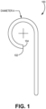
- FIG. 1 shows a view of a portion of a catheter 100.
- the catheter 100 includes a single lumen.
- the catheter 100 can be configured to deliver a high pressure contrast injection, such as for a TAVR procedure.
- the catheter 100 includes a proximal end (not shown) and a distal end 102.
- the proximal end of the catheter 100 can include a luer connection, such as a female luer connection.
- the female luer connection can be configured for adequate pressure retention during high pressure dye injections.
- the distal end 102 is a pigtail end, such that the distal end 102 includes a pigtail loop.
- the loop can be substantially circular, such that as when viewed from a side, such as shown in FIG. 1 , the pigtail loop can define at least a portion of a circle.
- the loop can have a diameter, such as diameter A shown in FIG. 1 .
- the loop has a diameter of at least 10 mm and not more than 20 mm.
- the loop has a diameter of at least 5 mm and not more than 30 mm.
- the pigtail loop extends 360 degrees.
- the pigtail loop extends 270 degrees, such as shown in FIG. 1 .
- the pigtail loop can extend at least 90 degrees and not more than 540 degrees.
- the pigtail loop can extend at least 270 degrees and not more than 360 degrees.
- the distal end 102 can define a distal hole 104, such as a hole from the catheter that is configured to deliver the contrast media.
- the distal hole 104 can be located at the end of the catheter 100.
- the distal hole 104 can be a continuation of a main lumen.
- the catheter 100 includes a main lumen, such as center lumen that extends from the proximal end of the catheter to the distal end 102.
- the main lumen can be configured to deliver a contracts media.
- the main lumen can have a substantially circular cross section.
- the catheter 100 can include a single lumen catheter with a braid reinforced polymer shaft.
- the catheter 100 can include Pebax.
- the catheter 100 can include a stainless steel.
- the catheter 100 can include Pebax and a stainless steel braid reinforcement.
- the catheter 100 defines one or more dye infusion holes.
- the dye infusion holes can be located at a minimum of 1 cm away from the distal tip.
- the dye infusion holes can be located at a maximum of 3 cm away from the distal tip.
- the dye infusion holes can be located between 1 cm and 3 cm away from the distal tip.
- the dye infusion holes can be located between 0.5 cm and 5 cm away from the distal tip.
- the dye infusion holes can be located at different distances away from the distal tip.
- the pigtail distal end 102 of the catheter is not braid reinforced. In an embodiment, the portion of the catheter that defines the one or more dye infusion holes is not braid reinforced. In an embodiment, the braid reinforcement terminates between the proximal end of the catheter and the dye infusion hole closest to the proximal end.
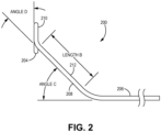
- FIG. 2 shows a view of a portion of a catheter 200.
- the catheter 200 includes a main shaft portion 206, a distal angled portion 208 and the pigtail loop 210.
- the pigtail loop 210 can define the distal end hole 204.
- the distal end hole 204 can be configured to deliver contrast media.
- the distal angled portion 208 defines one or more dye infusion holes 212.
- the distal angled portion can be at least 2 cm long and not longer than 5 cm, such as shown by length B in FIG. 2 .
- Alternative ranges for the length of the distal angled portion 208 are also possible, such as 1 cm to 6 cm, or 2 cm to 8 cm.
- the distal angled portion 208 is angled from the main shaft portion 206, such as represented by angle C in FIG. 2 .
- the distal angled portion 208 can be angled from the main shaft portion 206 by at least 25 degrees and not more than 45 degrees.
- the distal angled portion 208 is angled at least 15 degrees and not more than 60 degrees from the main shaft portion 206.
- the distal pigtail loop 210 is angled from distal angled portion 208, such as represented by angle D in FIG. 2 .
- the distal pigtail loop 210 is angled from distal angled portion 208, such as by at least 30 degrees and not more than 60 degrees.
- the distal pigtail loop 210 can be angled at least 20 degrees and not more than 90 degrees from the distal angled portion 208.
- the distal pigtail loop 210 can be configured such that it is about 90 degrees relative to the main shaft portion 206.
- the distal pigtail loop 210 is angled from the main shaft portion 206 by at least 60 degrees and not more than 120 degrees.
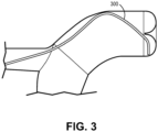
- FIG. 3 shows a view of a portion of a catheter 300 and a portion of an environment in which the catheter 300 can be used.
- the catheter 300 can be a diagnostic TAVR pigtail catheter.
- the catheter 300 can be optimally configured to opacify the non-coronary aortic cusp.
- the catheter 300 can allow for chamber opacification with little movement of the catheter 300, such as while the catheter 300 is positioned in the non-coronary cusp of the aortic root.
- the catheter can tend to lay along the greater curvature, placing the catheter into the right coronary cusp.
- the non-coronary cusp can lie posterior and leftward in relation to the right coronary cusp. Therefore the catheter 300 can include a left angle (causing displacement off the center line by approximately 2 cm) and an approximately 25 degree angle directed true posterior.
- An alternative catheter can have a similar displacement leftward (as most aortic roots are near 4 cm) and have a 40 degree angle directed posterior.
- the phrase “configured” describes a system, apparatus, or other structure that is constructed or configured to perform a particular task or adopt a particular configuration to.
- the phrase “configured” can be used interchangeably with other similar phrases such as arranged and configured, constructed and arranged, constructed, manufactured and arranged, and the like.
Landscapes
- Health & Medical Sciences (AREA)
- Life Sciences & Earth Sciences (AREA)
- Biomedical Technology (AREA)
- Anesthesiology (AREA)
- Heart & Thoracic Surgery (AREA)
- Hematology (AREA)
- Engineering & Computer Science (AREA)
- Animal Behavior & Ethology (AREA)
- General Health & Medical Sciences (AREA)
- Public Health (AREA)
- Veterinary Medicine (AREA)
- Biophysics (AREA)
- Pulmonology (AREA)
- Media Introduction/Drainage Providing Device (AREA)
- Infusion, Injection, And Reservoir Apparatuses (AREA)
Description
- The present application relates to a catheter. More specifically, the present application relates to a catheter for TAVR procedures.
- A transcatheter aortic valve replacement ("TAVR") can include the use of a catheter to replace a heart valve, such as the aortic valve of the heart. A TAVR procedure can be a minimally invasive surgical procedure to repair a valve in the heart without removing the old valve.
- In some scenarios a diagnostic pigtail catheter for opacifying the aortic cusps can be used in the TAVR procedure. Current pigtail diagnostic catheters for coronary interventions are typically made of two designs; 1) an angled pigtail catheter for facilitation of the catheter into the left ventricle or 2) a straight pigtail catheter for general purpose use in allowing for dye opacification of larger vascular structures. Neither catheter is designed for opacification of the aortic cusps or even more specifically for ideal placement into the non-coronary cusp of the aortic valve for appropriate coaxial alignment of the stented valve during transcatheter aortic valve replacement (TAVR).
-
US2006/0258978A1 describes a catheter employing fluid force to steer and/or shape the catheter. In one particular implementation, the catheter includes at least one actuating lumen operably associated with the shaft of the catheter. Upon introduction of fluid into the actuating lumen, the fluid creates a force which causes the catheter to bend. As such, fluid may be used to steer and/or shape the catheter. Other examples of pigtail catheter can be found inUS2006258978A1 ,US5163928A ,US4169464A orWO2011015218A1 . - Embodiments of the invention include a single lumen catheter for delivering high pressure contrast injection for TAVR procedures. The catheter comprising a main lumen for delivering contrast media extending from the proximal end to the distal pigtail end, a distal end hole for delivering contrast media, one or more side holes proximate of the end hole along the catheter shaft on the distal angled portion, a distal angled section of 2-5 cm in length that is angled at 25-45 degrees from the main catheter lumen axis, a distal pigtail configuration that is angled so its plane is 30-60 degrees from the axis of the distal section, a distal pigtail configuration that is oriented substantially 90 degrees relative to the main shaft of the catheter, and a distal pigtail loop that is 10-20 mm in diameter.
- This summary is an overview of some of the teachings of the present application and is not intended to be an exclusive or exhaustive treatment of the present subject matter. Further details are found in the detailed description and appended claims. Other aspects will be apparent to persons skilled in the art upon reading and understanding the following detailed description and viewing the drawings that form a part thereof, each of which is not to be taken in a limiting sense. The scope of the present invention is defined by the appended claims and their legal equivalents.
- The invention may be more completely understood in connection with the following drawings, in which:
-
FIG. 1 is a view of an end of a catheter, according to an embodiment. -
FIG. 2 is a view of a portion of a catheter, according to an embodiment. -
FIG. 3 is a view of a portion of a catheter and a portion of an environment in which it can be used, according to an embodiment. - While the invention is susceptible to various modifications and alternative forms, specifics thereof have been shown by way of example and drawings, and will be described in detail. It should be understood, however, that the invention is not limited to the particular embodiments described. On the contrary, the intention is to cover modifications, equivalents, and alternatives falling within the scope of the invention.
- The embodiments of the present technology described herein are not intended to be exhaustive or to limit the invention to the precise forms disclosed in the following detailed description. Rather, the embodiments are chosen and described so that others skilled in the art can appreciate and understand the principles and practices of the present invention.
- The publications and patents disclosed herein are provided solely for their disclosure. Nothing herein is to be construed as an admission that the inventors are not entitled to antedate any publication and/or patent, including any publication and/or patent cited herein.
- The catheter as described herein can provide a means to allow optimal chamber opacification without movement of the catheter while positioning the catheter into the non-coronary cusp.
-
FIG. 1 shows a view of a portion of acatheter 100. Thecatheter 100 includes a single lumen. Thecatheter 100 can be configured to deliver a high pressure contrast injection, such as for a TAVR procedure. In an embodiment, thecatheter 100 includes a proximal end (not shown) and adistal end 102. The proximal end of thecatheter 100 can include a luer connection, such as a female luer connection. The female luer connection can be configured for adequate pressure retention during high pressure dye injections. - The
distal end 102 is a pigtail end, such that thedistal end 102 includes a pigtail loop. The loop can be substantially circular, such that as when viewed from a side, such as shown inFIG. 1 , the pigtail loop can define at least a portion of a circle. The loop can have a diameter, such as diameter A shown inFIG. 1 . In an embodiment, the loop has a diameter of at least 10 mm and not more than 20 mm. In an embodiment, the loop has a diameter of at least 5 mm and not more than 30 mm. In an embodiment, the pigtail loop extends 360 degrees. In an alternative embodiment, the pigtail loop extends 270 degrees, such as shown inFIG. 1 . In an embodiment, the pigtail loop can extend at least 90 degrees and not more than 540 degrees. In an embodiment, the pigtail loop can extend at least 270 degrees and not more than 360 degrees. - The
distal end 102 can define adistal hole 104, such as a hole from the catheter that is configured to deliver the contrast media. In an embodiment, thedistal hole 104 can be located at the end of thecatheter 100. In an embodiment, thedistal hole 104 can be a continuation of a main lumen. - The
catheter 100 includes a main lumen, such as center lumen that extends from the proximal end of the catheter to thedistal end 102. The main lumen can be configured to deliver a contracts media. The main lumen can have a substantially circular cross section. - The
catheter 100 can include a single lumen catheter with a braid reinforced polymer shaft. Thecatheter 100 can include Pebax. Thecatheter 100 can include a stainless steel. In an embodiment, thecatheter 100 can include Pebax and a stainless steel braid reinforcement. In an embodiment, thecatheter 100 can be configured for contrast injection pressures of up to at least 1200 psi (1psi =6894.7Pa). - The
catheter 100 defines one or more dye infusion holes. The dye infusion holes can be located at a minimum of 1 cm away from the distal tip. The dye infusion holes can be located at a maximum of 3 cm away from the distal tip. In an embodiment, the dye infusion holes can be located between 1 cm and 3 cm away from the distal tip. In an embodiment, the dye infusion holes can be located between 0.5 cm and 5 cm away from the distal tip. In an embodiment, the dye infusion holes can be located at different distances away from the distal tip. - In an embodiment, there is at least 1 dye infusion hole. In an embodiment, there can be 5 or less dye infusion holes. In an embodiment, there can be 2, 3, or 4 dye infusion holes. In an embodiment, the pigtail
distal end 102 of the catheter is not braid reinforced. In an embodiment, the portion of the catheter that defines the one or more dye infusion holes is not braid reinforced. In an embodiment, the braid reinforcement terminates between the proximal end of the catheter and the dye infusion hole closest to the proximal end. -
FIG. 2 shows a view of a portion of acatheter 200. Thecatheter 200 includes amain shaft portion 206, a distalangled portion 208 and thepigtail loop 210. Thepigtail loop 210 can define thedistal end hole 204. Thedistal end hole 204 can be configured to deliver contrast media. - The distal
angled portion 208 defines one or more dye infusion holes 212. In an embodiment, the distal angled portion can be at least 2 cm long and not longer than 5 cm, such as shown by length B inFIG. 2 . Alternative ranges for the length of the distalangled portion 208 are also possible, such as 1 cm to 6 cm, or 2 cm to 8 cm. The distalangled portion 208 is angled from themain shaft portion 206, such as represented by angle C inFIG. 2 . The distalangled portion 208 can be angled from themain shaft portion 206 by at least 25 degrees and not more than 45 degrees. In an alternative embodiment, the distalangled portion 208 is angled at least 15 degrees and not more than 60 degrees from themain shaft portion 206. - The
distal pigtail loop 210 is angled from distalangled portion 208, such as represented by angle D inFIG. 2 . Thedistal pigtail loop 210 is angled from distalangled portion 208, such as by at least 30 degrees and not more than 60 degrees. In an alternative embodiment, thedistal pigtail loop 210 can be angled at least 20 degrees and not more than 90 degrees from the distalangled portion 208. - The
distal pigtail loop 210 can be configured such that it is about 90 degrees relative to themain shaft portion 206. Thedistal pigtail loop 210 is angled from themain shaft portion 206 by at least 60 degrees and not more than 120 degrees. -
FIG. 3 shows a view of a portion of acatheter 300 and a portion of an environment in which thecatheter 300 can be used. In an embodiment, thecatheter 300 can be a diagnostic TAVR pigtail catheter. Thecatheter 300 can be optimally configured to opacify the non-coronary aortic cusp. Thecatheter 300 can allow for chamber opacification with little movement of thecatheter 300, such as while thecatheter 300 is positioned in the non-coronary cusp of the aortic root. - In some TAVR procedures, as a guidewire and catheter track around the aortic arch, the catheter can tend to lay along the greater curvature, placing the catheter into the right coronary cusp. The non-coronary cusp can lie posterior and leftward in relation to the right coronary cusp. Therefore the
catheter 300 can include a left angle (causing displacement off the center line by approximately 2 cm) and an approximately 25 degree angle directed true posterior. An alternative catheter can have a similar displacement leftward (as most aortic roots are near 4 cm) and have a 40 degree angle directed posterior. - It should be noted that, as used in this specification and the appended claims, the singular forms "a," "an," and "the" include plural referents unless the content clearly dictates otherwise. Thus, for example, reference to a composition containing "a compound" includes a mixture of two or more compounds. It should also be noted that the term "or" is generally employed in its sense including "and/or" unless the content clearly dictates otherwise.
- It should also be noted that, as used in this specification and the appended claims, the phrase "configured" describes a system, apparatus, or other structure that is constructed or configured to perform a particular task or adopt a particular configuration to. The phrase "configured" can be used interchangeably with other similar phrases such as arranged and configured, constructed and arranged, constructed, manufactured and arranged, and the like.
- All publications and patent applications in this specification are indicative of the level of ordinary skill in the art to which this invention pertains.
- The invention has been described with reference to various specific and preferred embodiments and techniques. However, it should be understood that many variations and modifications may be made while remaining within the scope of the invention.
Claims (12)
- A catheter (100,200,300) for delivering a fluid media comprising:a main catheter portion (206) extending along a main catheter lumen axis from a proximal catheter end toward a distal catheter end (102);an angled assembly coupled with the main catheter portion (206) near the distal catheter end (102), the angled assembly includes:a pigtail loop (210) having a plane, the plane being at a first angle relative to the main catheter lumen axis of the main catheter portion, wherein the first angle is at least 60 degrees and not more than 120 degrees,a distal angled portion (208) extending from the main catheter portion (206) to the pigtail loop (210), the distal angled portion (208) extending from the main catheter portion (206) at a second angle (C) relative to the main catheter portion (206), andwherein the pig tail loop (210) extends from the distal angled portion (208) at a third angle (D) relative to the distal angled portion (208);wherein one or more of the pigtail loop (210) or the distal angled portion (208) includes at least one fluid media hole (212) configured for dispensing a fluid media, andcharacterised in thatthe main catheter lumen axis intersects the plane of the pigtail loop (210) at an offset point displaced from the pigtail loop.
- The catheter of claim 1, wherein the distal angled portion (208) is straight between the main catheter portion (206) and the pigtail loop (210).
- The catheter of claim 1, wherein the main catheter portion (206) includes a main lumen extending from the proximal catheter end toward the distal catheter end (102).
- The catheter of claim 3, wherein the main lumen extends from the main catheter portion (206) into the distal angled portion (208), and the main lumen is in communication with the at least one fluid media hole (212) in the distal angled portion (208) configured for dispensing the fluid media.
- The catheter of claim 4, wherein the main lumen extends from the distal angled portion (208) into the pigtail loop (210), and the main lumen is in communication with the at least one fluid media hole (212) in the pigtail loop (210) and the distal angled portion (208) configured for dispensing the fluid media.
- The catheter of claim 1, wherein the at least one fluid media hole includes a distal end hole (104) in the pigtail loop (210).
- The catheter of claim 1, wherein the distal angled portion (208) is 2 to 5 centimeters in length and the second angle (C) is between 25 to 45 degrees relative to an axis of the main catheter portion (206).
- The catheter of claim 1, wherein the pigtail loop (210) is 10 to 20 millimeters in diameter and the first angle is about 90 degrees relative to an axis of the main catheter portion (206).
- The catheter of claim 1, wherein the third angle (D) of the pigtail loop (210) is between 30 to 60 degrees relative to an axis of the distal angled portion (208).
- The catheter of claim 1, wherein the pigtail loop (210) is aligned along a plane.
- The catheter of claim 1, wherein each of the pigtail loop (210) and the distal angled portion (208) includes a plurality of fluid media holes (212).
- The catheter of claim 1, wherein the main catheter portion (206) and at least one of the distal angled portion (208) or the pigtail loop (210) includes a main lumen in communication with the at least one fluid media hole (212).
Applications Claiming Priority (2)
| Application Number | Priority Date | Filing Date | Title |
|---|---|---|---|
| US201462068403P | 2014-10-24 | 2014-10-24 | |
| PCT/US2015/057147 WO2016065278A1 (en) | 2014-10-24 | 2015-10-23 | Catheter for tavr procedures |
Publications (3)
| Publication Number | Publication Date |
|---|---|
| EP3209361A1 EP3209361A1 (en) | 2017-08-30 |
| EP3209361A4 EP3209361A4 (en) | 2018-03-28 |
| EP3209361B1 true EP3209361B1 (en) | 2023-08-09 |
Family
ID=55761636
Family Applications (1)
| Application Number | Title | Priority Date | Filing Date |
|---|---|---|---|
| EP15852982.6A Active EP3209361B1 (en) | 2014-10-24 | 2015-10-23 | Catheter for tavr procedures |
Country Status (6)
| Country | Link |
|---|---|
| US (1) | US11179544B2 (en) |
| EP (1) | EP3209361B1 (en) |
| JP (1) | JP6785232B2 (en) |
| CA (1) | CA2965317C (en) |
| MX (1) | MX2017005331A (en) |
| WO (1) | WO2016065278A1 (en) |
Families Citing this family (3)
| Publication number | Priority date | Publication date | Assignee | Title |
|---|---|---|---|---|
| EP3209361B1 (en) | 2014-10-24 | 2023-08-09 | Helmer, Gregory | Catheter for tavr procedures |
| KR20210154174A (en) * | 2019-04-18 | 2021-12-20 | 아비오메드, 인크. | Variable stiffness distal extension for blood pump systems |
| EP4543522A1 (en) * | 2022-06-21 | 2025-04-30 | St. Jude Medical, Cardiology Division, Inc. | Single-catheter enabled pda access and occluder deployment and recapture |
Family Cites Families (15)
| Publication number | Priority date | Publication date | Assignee | Title |
|---|---|---|---|---|
| US4169464A (en) * | 1977-12-16 | 1979-10-02 | Cordis Corporation | Catheter for selective catheterization of aortic branches |
| JPS60190968A (en) | 1984-01-30 | 1985-09-28 | マリンクロツド・インコ−ポレイテツド | Catheter for contrast photographing of coronary arteries |
| US4694838A (en) * | 1984-01-30 | 1987-09-22 | Mallinckrodt, Inc. | Loop coronary catheter |
| US4747840A (en) * | 1986-09-17 | 1988-05-31 | Ladika Joseph E | Selective pulmonary arteriograph catheter |
| US5163928A (en) | 1991-01-07 | 1992-11-17 | Franklin Electronic Publishers, Incorporated | Self-centering catheter |
| JP3527378B2 (en) * | 1997-01-31 | 2004-05-17 | テルモ株式会社 | Contrast catheter |
| JP3643233B2 (en) | 1998-03-03 | 2005-04-27 | テルモ株式会社 | Contrast catheter |
| JP2002186670A (en) | 2000-12-20 | 2002-07-02 | Toray Ind Inc | Angiographic catheter |
| JP2004267496A (en) | 2003-03-10 | 2004-09-30 | Toray Ind Inc | Angiographic catheter |
| US7101362B2 (en) * | 2003-07-02 | 2006-09-05 | St. Jude Medical, Atrial Fibrillation Division, Inc. | Steerable and shapable catheter employing fluid force |
| JP4209753B2 (en) | 2003-08-21 | 2009-01-14 | 川澄化学工業株式会社 | Heart left ventricular catheter |
| JP3151538U (en) | 2009-04-16 | 2009-06-25 | トノクラ医科工業株式会社 | catheter |
| WO2011015218A1 (en) * | 2009-08-06 | 2011-02-10 | Ls Medcap Gmbh | Catheter with two fenestrations |
| KR20150100709A (en) | 2012-12-05 | 2015-09-02 | 마이클 비. 맥도날드 | Tavr ventricular catheter |
| EP3209361B1 (en) | 2014-10-24 | 2023-08-09 | Helmer, Gregory | Catheter for tavr procedures |
-
2015
- 2015-10-23 EP EP15852982.6A patent/EP3209361B1/en active Active
- 2015-10-23 WO PCT/US2015/057147 patent/WO2016065278A1/en not_active Ceased
- 2015-10-23 CA CA2965317A patent/CA2965317C/en active Active
- 2015-10-23 MX MX2017005331A patent/MX2017005331A/en unknown
- 2015-10-23 JP JP2017540975A patent/JP6785232B2/en not_active Expired - Fee Related
- 2015-10-23 US US15/521,579 patent/US11179544B2/en active Active
Also Published As
| Publication number | Publication date |
|---|---|
| JP2018502673A (en) | 2018-02-01 |
| WO2016065278A1 (en) | 2016-04-28 |
| JP6785232B2 (en) | 2020-11-18 |
| US11179544B2 (en) | 2021-11-23 |
| MX2017005331A (en) | 2018-08-15 |
| US20180200477A1 (en) | 2018-07-19 |
| EP3209361A1 (en) | 2017-08-30 |
| EP3209361A4 (en) | 2018-03-28 |
| CA2965317C (en) | 2023-03-14 |
| CA2965317A1 (en) | 2016-04-28 |
Similar Documents
| Publication | Publication Date | Title |
|---|---|---|
| US20220241581A1 (en) | Cannula assembly | |
| JP6412505B2 (en) | Steerable guidewire and method of use | |
| CN115023258B (en) | Guide devices for vascular catheters | |
| US6251092B1 (en) | Deflectable guiding catheter | |
| KR102870063B1 (en) | Guidewire for cannula placement | |
| EP2687254B1 (en) | Coronary artery catheter | |
| US7818040B2 (en) | Deflectable medical therapy delivery device having common lumen profile | |
| EP2777749B1 (en) | Balloon dilation catheter | |
| US9039676B2 (en) | Apparatus and methods for catheter steerability | |
| KR20210154174A (en) | Variable stiffness distal extension for blood pump systems | |
| WO2015111680A1 (en) | Catheter and catheter hub | |
| EP1663371B1 (en) | Deflectable medical therapy delivery device having common lumen profile | |
| US20190224456A1 (en) | Graded stiffness guidewire | |
| US11179544B2 (en) | Catheter for TAVR procedures | |
| NZ781705A (en) | Introducer needle and related catheter insertion device | |
| US20110190784A1 (en) | Catheter with removable shaping skeleton and methods of using and making same | |
| WO2007055850A3 (en) | Infusion guidewire | |
| US20240382233A1 (en) | Pigtail dilator system | |
| US20210330931A1 (en) | Pediatric catheter | |
| NZ768979A (en) | Catheter system with remote instrument delivery |
Legal Events
| Date | Code | Title | Description |
|---|---|---|---|
| STAA | Information on the status of an ep patent application or granted ep patent |
Free format text: STATUS: THE INTERNATIONAL PUBLICATION HAS BEEN MADE |
|
| PUAI | Public reference made under article 153(3) epc to a published international application that has entered the european phase |
Free format text: ORIGINAL CODE: 0009012 |
|
| STAA | Information on the status of an ep patent application or granted ep patent |
Free format text: STATUS: REQUEST FOR EXAMINATION WAS MADE |
|
| 17P | Request for examination filed |
Effective date: 20170522 |
|
| AK | Designated contracting states |
Kind code of ref document: A1 Designated state(s): AL AT BE BG CH CY CZ DE DK EE ES FI FR GB GR HR HU IE IS IT LI LT LU LV MC MK MT NL NO PL PT RO RS SE SI SK SM TR |
|
| AX | Request for extension of the european patent |
Extension state: BA ME |
|
| DAV | Request for validation of the european patent (deleted) | ||
| DAX | Request for extension of the european patent (deleted) | ||
| A4 | Supplementary search report drawn up and despatched |
Effective date: 20180223 |
|
| RIC1 | Information provided on ipc code assigned before grant |
Ipc: A61M 25/00 20060101AFI20180219BHEP Ipc: A61M 31/00 20060101ALI20180219BHEP Ipc: A61F 2/24 20060101ALI20180219BHEP |
|
| STAA | Information on the status of an ep patent application or granted ep patent |
Free format text: STATUS: EXAMINATION IS IN PROGRESS |
|
| 17Q | First examination report despatched |
Effective date: 20200921 |
|
| GRAP | Despatch of communication of intention to grant a patent |
Free format text: ORIGINAL CODE: EPIDOSNIGR1 |
|
| STAA | Information on the status of an ep patent application or granted ep patent |
Free format text: STATUS: GRANT OF PATENT IS INTENDED |
|
| INTG | Intention to grant announced |
Effective date: 20230227 |
|
| GRAS | Grant fee paid |
Free format text: ORIGINAL CODE: EPIDOSNIGR3 |
|
| GRAA | (expected) grant |
Free format text: ORIGINAL CODE: 0009210 |
|
| STAA | Information on the status of an ep patent application or granted ep patent |
Free format text: STATUS: THE PATENT HAS BEEN GRANTED |
|
| AK | Designated contracting states |
Kind code of ref document: B1 Designated state(s): AL AT BE BG CH CY CZ DE DK EE ES FI FR GB GR HR HU IE IS IT LI LT LU LV MC MK MT NL NO PL PT RO RS SE SI SK SM TR |
|
| REG | Reference to a national code |
Ref country code: GB Ref legal event code: FG4D |
|
| REG | Reference to a national code |
Ref country code: CH Ref legal event code: EP |
|
| REG | Reference to a national code |
Ref country code: DE Ref legal event code: R096 Ref document number: 602015085083 Country of ref document: DE |
|
| REG | Reference to a national code |
Ref country code: IE Ref legal event code: FG4D |
|
| REG | Reference to a national code |
Ref country code: GB Ref legal event code: 732E Free format text: REGISTERED BETWEEN 20230914 AND 20230920 |
|
| REG | Reference to a national code |
Ref country code: DE Ref legal event code: R081 Ref document number: 602015085083 Country of ref document: DE Owner name: NORMEDIX, INC., PLYMOUTH, US Free format text: FORMER OWNER: HELMER, GREGORY, EXCELSIOR, MN, US |
|
| REG | Reference to a national code |
Ref country code: LT Ref legal event code: MG9D |
|
| REG | Reference to a national code |
Ref country code: NL Ref legal event code: MP Effective date: 20230809 |
|
| REG | Reference to a national code |
Ref country code: AT Ref legal event code: MK05 Ref document number: 1596778 Country of ref document: AT Kind code of ref document: T Effective date: 20230809 |
|
| PG25 | Lapsed in a contracting state [announced via postgrant information from national office to epo] |
Ref country code: GR Free format text: LAPSE BECAUSE OF FAILURE TO SUBMIT A TRANSLATION OF THE DESCRIPTION OR TO PAY THE FEE WITHIN THE PRESCRIBED TIME-LIMIT Effective date: 20231110 |
|
| PG25 | Lapsed in a contracting state [announced via postgrant information from national office to epo] |
Ref country code: IS Free format text: LAPSE BECAUSE OF FAILURE TO SUBMIT A TRANSLATION OF THE DESCRIPTION OR TO PAY THE FEE WITHIN THE PRESCRIBED TIME-LIMIT Effective date: 20231209 |
|
| PG25 | Lapsed in a contracting state [announced via postgrant information from national office to epo] |
Ref country code: SE Free format text: LAPSE BECAUSE OF FAILURE TO SUBMIT A TRANSLATION OF THE DESCRIPTION OR TO PAY THE FEE WITHIN THE PRESCRIBED TIME-LIMIT Effective date: 20230809 Ref country code: RS Free format text: LAPSE BECAUSE OF FAILURE TO SUBMIT A TRANSLATION OF THE DESCRIPTION OR TO PAY THE FEE WITHIN THE PRESCRIBED TIME-LIMIT Effective date: 20230809 Ref country code: PT Free format text: LAPSE BECAUSE OF FAILURE TO SUBMIT A TRANSLATION OF THE DESCRIPTION OR TO PAY THE FEE WITHIN THE PRESCRIBED TIME-LIMIT Effective date: 20231211 Ref country code: NO Free format text: LAPSE BECAUSE OF FAILURE TO SUBMIT A TRANSLATION OF THE DESCRIPTION OR TO PAY THE FEE WITHIN THE PRESCRIBED TIME-LIMIT Effective date: 20231109 Ref country code: NL Free format text: LAPSE BECAUSE OF FAILURE TO SUBMIT A TRANSLATION OF THE DESCRIPTION OR TO PAY THE FEE WITHIN THE PRESCRIBED TIME-LIMIT Effective date: 20230809 Ref country code: LV Free format text: LAPSE BECAUSE OF FAILURE TO SUBMIT A TRANSLATION OF THE DESCRIPTION OR TO PAY THE FEE WITHIN THE PRESCRIBED TIME-LIMIT Effective date: 20230809 Ref country code: LT Free format text: LAPSE BECAUSE OF FAILURE TO SUBMIT A TRANSLATION OF THE DESCRIPTION OR TO PAY THE FEE WITHIN THE PRESCRIBED TIME-LIMIT Effective date: 20230809 Ref country code: IS Free format text: LAPSE BECAUSE OF FAILURE TO SUBMIT A TRANSLATION OF THE DESCRIPTION OR TO PAY THE FEE WITHIN THE PRESCRIBED TIME-LIMIT Effective date: 20231209 Ref country code: HR Free format text: LAPSE BECAUSE OF FAILURE TO SUBMIT A TRANSLATION OF THE DESCRIPTION OR TO PAY THE FEE WITHIN THE PRESCRIBED TIME-LIMIT Effective date: 20230809 Ref country code: GR Free format text: LAPSE BECAUSE OF FAILURE TO SUBMIT A TRANSLATION OF THE DESCRIPTION OR TO PAY THE FEE WITHIN THE PRESCRIBED TIME-LIMIT Effective date: 20231110 Ref country code: FI Free format text: LAPSE BECAUSE OF FAILURE TO SUBMIT A TRANSLATION OF THE DESCRIPTION OR TO PAY THE FEE WITHIN THE PRESCRIBED TIME-LIMIT Effective date: 20230809 Ref country code: AT Free format text: LAPSE BECAUSE OF FAILURE TO SUBMIT A TRANSLATION OF THE DESCRIPTION OR TO PAY THE FEE WITHIN THE PRESCRIBED TIME-LIMIT Effective date: 20230809 |
|
| PG25 | Lapsed in a contracting state [announced via postgrant information from national office to epo] |
Ref country code: PL Free format text: LAPSE BECAUSE OF FAILURE TO SUBMIT A TRANSLATION OF THE DESCRIPTION OR TO PAY THE FEE WITHIN THE PRESCRIBED TIME-LIMIT Effective date: 20230809 |
|
| PG25 | Lapsed in a contracting state [announced via postgrant information from national office to epo] |
Ref country code: ES Free format text: LAPSE BECAUSE OF FAILURE TO SUBMIT A TRANSLATION OF THE DESCRIPTION OR TO PAY THE FEE WITHIN THE PRESCRIBED TIME-LIMIT Effective date: 20230809 |
|
| PG25 | Lapsed in a contracting state [announced via postgrant information from national office to epo] |
Ref country code: SM Free format text: LAPSE BECAUSE OF FAILURE TO SUBMIT A TRANSLATION OF THE DESCRIPTION OR TO PAY THE FEE WITHIN THE PRESCRIBED TIME-LIMIT Effective date: 20230809 Ref country code: RO Free format text: LAPSE BECAUSE OF FAILURE TO SUBMIT A TRANSLATION OF THE DESCRIPTION OR TO PAY THE FEE WITHIN THE PRESCRIBED TIME-LIMIT Effective date: 20230809 Ref country code: ES Free format text: LAPSE BECAUSE OF FAILURE TO SUBMIT A TRANSLATION OF THE DESCRIPTION OR TO PAY THE FEE WITHIN THE PRESCRIBED TIME-LIMIT Effective date: 20230809 Ref country code: EE Free format text: LAPSE BECAUSE OF FAILURE TO SUBMIT A TRANSLATION OF THE DESCRIPTION OR TO PAY THE FEE WITHIN THE PRESCRIBED TIME-LIMIT Effective date: 20230809 Ref country code: DK Free format text: LAPSE BECAUSE OF FAILURE TO SUBMIT A TRANSLATION OF THE DESCRIPTION OR TO PAY THE FEE WITHIN THE PRESCRIBED TIME-LIMIT Effective date: 20230809 Ref country code: CZ Free format text: LAPSE BECAUSE OF FAILURE TO SUBMIT A TRANSLATION OF THE DESCRIPTION OR TO PAY THE FEE WITHIN THE PRESCRIBED TIME-LIMIT Effective date: 20230809 Ref country code: SK Free format text: LAPSE BECAUSE OF FAILURE TO SUBMIT A TRANSLATION OF THE DESCRIPTION OR TO PAY THE FEE WITHIN THE PRESCRIBED TIME-LIMIT Effective date: 20230809 |
|
| REG | Reference to a national code |
Ref country code: DE Ref legal event code: R097 Ref document number: 602015085083 Country of ref document: DE |
|
| PG25 | Lapsed in a contracting state [announced via postgrant information from national office to epo] |
Ref country code: IT Free format text: LAPSE BECAUSE OF FAILURE TO SUBMIT A TRANSLATION OF THE DESCRIPTION OR TO PAY THE FEE WITHIN THE PRESCRIBED TIME-LIMIT Effective date: 20230809 Ref country code: MC Free format text: LAPSE BECAUSE OF FAILURE TO SUBMIT A TRANSLATION OF THE DESCRIPTION OR TO PAY THE FEE WITHIN THE PRESCRIBED TIME-LIMIT Effective date: 20230809 |
|
| REG | Reference to a national code |
Ref country code: CH Ref legal event code: PL |
|
| PLBE | No opposition filed within time limit |
Free format text: ORIGINAL CODE: 0009261 |
|
| STAA | Information on the status of an ep patent application or granted ep patent |
Free format text: STATUS: NO OPPOSITION FILED WITHIN TIME LIMIT |
|
| REG | Reference to a national code |
Ref country code: BE Ref legal event code: MM Effective date: 20231031 |
|
| PG25 | Lapsed in a contracting state [announced via postgrant information from national office to epo] |
Ref country code: LU Free format text: LAPSE BECAUSE OF NON-PAYMENT OF DUE FEES Effective date: 20231023 |
|
| PG25 | Lapsed in a contracting state [announced via postgrant information from national office to epo] |
Ref country code: LU Free format text: LAPSE BECAUSE OF NON-PAYMENT OF DUE FEES Effective date: 20231023 |
|
| 26N | No opposition filed |
Effective date: 20240513 |
|
| PG25 | Lapsed in a contracting state [announced via postgrant information from national office to epo] |
Ref country code: CH Free format text: LAPSE BECAUSE OF NON-PAYMENT OF DUE FEES Effective date: 20231031 |
|
| PG25 | Lapsed in a contracting state [announced via postgrant information from national office to epo] |
Ref country code: CH Free format text: LAPSE BECAUSE OF NON-PAYMENT OF DUE FEES Effective date: 20231031 Ref country code: SI Free format text: LAPSE BECAUSE OF FAILURE TO SUBMIT A TRANSLATION OF THE DESCRIPTION OR TO PAY THE FEE WITHIN THE PRESCRIBED TIME-LIMIT Effective date: 20230809 |
|
| PG25 | Lapsed in a contracting state [announced via postgrant information from national office to epo] |
Ref country code: BE Free format text: LAPSE BECAUSE OF NON-PAYMENT OF DUE FEES Effective date: 20231031 |
|
| PG25 | Lapsed in a contracting state [announced via postgrant information from national office to epo] |
Ref country code: BG Free format text: LAPSE BECAUSE OF FAILURE TO SUBMIT A TRANSLATION OF THE DESCRIPTION OR TO PAY THE FEE WITHIN THE PRESCRIBED TIME-LIMIT Effective date: 20230809 |
|
| PG25 | Lapsed in a contracting state [announced via postgrant information from national office to epo] |
Ref country code: BG Free format text: LAPSE BECAUSE OF FAILURE TO SUBMIT A TRANSLATION OF THE DESCRIPTION OR TO PAY THE FEE WITHIN THE PRESCRIBED TIME-LIMIT Effective date: 20230809 |
|
| PG25 | Lapsed in a contracting state [announced via postgrant information from national office to epo] |
Ref country code: CY Free format text: LAPSE BECAUSE OF FAILURE TO SUBMIT A TRANSLATION OF THE DESCRIPTION OR TO PAY THE FEE WITHIN THE PRESCRIBED TIME-LIMIT; INVALID AB INITIO Effective date: 20151023 |
|
| PG25 | Lapsed in a contracting state [announced via postgrant information from national office to epo] |
Ref country code: HU Free format text: LAPSE BECAUSE OF FAILURE TO SUBMIT A TRANSLATION OF THE DESCRIPTION OR TO PAY THE FEE WITHIN THE PRESCRIBED TIME-LIMIT; INVALID AB INITIO Effective date: 20151023 |
|
| PGFP | Annual fee paid to national office [announced via postgrant information from national office to epo] |
Ref country code: GB Payment date: 20250904 Year of fee payment: 11 |
|
| PGFP | Annual fee paid to national office [announced via postgrant information from national office to epo] |
Ref country code: FR Payment date: 20250908 Year of fee payment: 11 |
|
| PGFP | Annual fee paid to national office [announced via postgrant information from national office to epo] |
Ref country code: IE Payment date: 20250909 Year of fee payment: 11 |
|
| PG25 | Lapsed in a contracting state [announced via postgrant information from national office to epo] |
Ref country code: TR Free format text: LAPSE BECAUSE OF FAILURE TO SUBMIT A TRANSLATION OF THE DESCRIPTION OR TO PAY THE FEE WITHIN THE PRESCRIBED TIME-LIMIT Effective date: 20230809 |
|
| PGFP | Annual fee paid to national office [announced via postgrant information from national office to epo] |
Ref country code: DE Payment date: 20250902 Year of fee payment: 11 |