EP3209014A1 - Image shooting apparatus, image shooting method, image shooting program, and recording medium that records the image shooting program - Google Patents
Image shooting apparatus, image shooting method, image shooting program, and recording medium that records the image shooting program Download PDFInfo
- Publication number
- EP3209014A1 EP3209014A1 EP16204384.8A EP16204384A EP3209014A1 EP 3209014 A1 EP3209014 A1 EP 3209014A1 EP 16204384 A EP16204384 A EP 16204384A EP 3209014 A1 EP3209014 A1 EP 3209014A1
- Authority
- EP
- European Patent Office
- Prior art keywords
- image
- recovery
- image shooting
- recovered
- processing
- Prior art date
- Legal status (The legal status is an assumption and is not a legal conclusion. Google has not performed a legal analysis and makes no representation as to the accuracy of the status listed.)
- Granted
Links
Images









Classifications
-
- G—PHYSICS
- G06—COMPUTING OR CALCULATING; COUNTING
- G06T—IMAGE DATA PROCESSING OR GENERATION, IN GENERAL
- G06T5/00—Image enhancement or restoration
- G06T5/73—Deblurring; Sharpening
-
- G—PHYSICS
- G06—COMPUTING OR CALCULATING; COUNTING
- G06T—IMAGE DATA PROCESSING OR GENERATION, IN GENERAL
- G06T5/00—Image enhancement or restoration
- G06T5/10—Image enhancement or restoration using non-spatial domain filtering
-
- G—PHYSICS
- G06—COMPUTING OR CALCULATING; COUNTING
- G06T—IMAGE DATA PROCESSING OR GENERATION, IN GENERAL
- G06T5/00—Image enhancement or restoration
- G06T5/20—Image enhancement or restoration using local operators
-
- H—ELECTRICITY
- H04—ELECTRIC COMMUNICATION TECHNIQUE
- H04N—PICTORIAL COMMUNICATION, e.g. TELEVISION
- H04N23/00—Cameras or camera modules comprising electronic image sensors; Control thereof
- H04N23/50—Constructional details
- H04N23/54—Mounting of pick-up tubes, electronic image sensors, deviation or focusing coils
-
- H—ELECTRICITY
- H04—ELECTRIC COMMUNICATION TECHNIQUE
- H04N—PICTORIAL COMMUNICATION, e.g. TELEVISION
- H04N23/00—Cameras or camera modules comprising electronic image sensors; Control thereof
- H04N23/60—Control of cameras or camera modules
- H04N23/617—Upgrading or updating of programs or applications for camera control
-
- H—ELECTRICITY
- H04—ELECTRIC COMMUNICATION TECHNIQUE
- H04N—PICTORIAL COMMUNICATION, e.g. TELEVISION
- H04N23/00—Cameras or camera modules comprising electronic image sensors; Control thereof
- H04N23/60—Control of cameras or camera modules
- H04N23/67—Focus control based on electronic image sensor signals
-
- H—ELECTRICITY
- H04—ELECTRIC COMMUNICATION TECHNIQUE
- H04N—PICTORIAL COMMUNICATION, e.g. TELEVISION
- H04N23/00—Cameras or camera modules comprising electronic image sensors; Control thereof
- H04N23/70—Circuitry for compensating brightness variation in the scene
- H04N23/71—Circuitry for evaluating the brightness variation
-
- H—ELECTRICITY
- H04—ELECTRIC COMMUNICATION TECHNIQUE
- H04N—PICTORIAL COMMUNICATION, e.g. TELEVISION
- H04N23/00—Cameras or camera modules comprising electronic image sensors; Control thereof
- H04N23/80—Camera processing pipelines; Components thereof
-
- H—ELECTRICITY
- H04—ELECTRIC COMMUNICATION TECHNIQUE
- H04N—PICTORIAL COMMUNICATION, e.g. TELEVISION
- H04N5/00—Details of television systems
- H04N5/222—Studio circuitry; Studio devices; Studio equipment
- H04N5/2224—Studio circuitry; Studio devices; Studio equipment related to virtual studio applications
- H04N5/2226—Determination of depth image, e.g. for foreground/background separation
-
- G—PHYSICS
- G06—COMPUTING OR CALCULATING; COUNTING
- G06T—IMAGE DATA PROCESSING OR GENERATION, IN GENERAL
- G06T2207/00—Indexing scheme for image analysis or image enhancement
- G06T2207/10—Image acquisition modality
- G06T2207/10024—Color image
-
- G—PHYSICS
- G06—COMPUTING OR CALCULATING; COUNTING
- G06T—IMAGE DATA PROCESSING OR GENERATION, IN GENERAL
- G06T2207/00—Indexing scheme for image analysis or image enhancement
- G06T2207/20—Special algorithmic details
- G06T2207/20024—Filtering details
- G06T2207/20032—Median filtering
Definitions
- the invention relates to an image shooting apparatus, an image shooting method, an image shooting program, and a recording medium that records the image shooting program, in particular, to an image shooting apparatus and an image shooting method that extend a depth of field by recovering a blurred image, an image shooting program, and a recording medium that records the image shooting program.
- a distance is calculated by using a distance detection sensor or multiple image shooting portions, and recovery processing is performed based on PSF data corresponding to each distance obtained by rough estimation.
- a recovery filter that minimizes a mean square error of a frequency domain is designed in consideration of all PSFs corresponding to multiple defocusing locations.
- non-patent document 1 discloses a technology called "auto focus (auto focus, AF)" carried in digital cameras that start to be sold by Panasonic (Panasonic) Corporation since April, 2014.
- a depth from defocus (Depth from Defocus, DFD) of a distance is calculated based on analysis according to a blur quantity; after a distance from two images to a photographed object is calculated, a blur model is derived to make a focus image.
- Non-patent document 2 discloses calculation of sharpnesses of images.
- an objective of the invention lies in providing an image shooting apparatus and an image shooting method that obtain a recovered image with high precision by using an optimal PSF without deriving an image shooting distance of a photographed object, an image shooting program, and a recording medium that records the program.
- the image shooting apparatus of the invention is characterized by including: an optical system, including one or more than one lenses or the lens and an optical element; an image shooting element, configured at a location further to the rear of the optical system; an image recovery processing portion, configured to perform image processing and recovery processing on image data obtained by the image shooting element; and a recovered image output portion, configured to output an image recovered by the image recovery processing portion; and the image recovery processing portion includes: a recovery filter storage portion, configured to store multiple recovery filters pre-manufactured by using multiple point spread functions (PSF) corresponding to multiple different distances; a recovery filter processing portion, configured to obtain multiple middle candidate images respectively recovered by using the multiple recovery filters according to the image data; and an image comment portion, configured to separately comment on profiles of the multiple candidate images to output an optimal middle candidate image as a recovery processing result.
- PSF point spread functions
- an objective of the optical system lies in extending a depth of field, as long as the PSF is used to perform recovery.
- the lens may be either a spherical lens or a non-spherical lens, or a suitable combination may be performed in a case in which there are multiple lenses.
- the optical element for example, may be a light diffusion plate, a phase plate, or a diffraction grating. However, the invention is not limited thereto.
- the image recovery processing portion may further include: an image area designation portion, configured to designate an image area, used as an object, in the recovery filter processing portion; and an excluded area designation portion, configured to designate an area, which should be excluded from the object by the image comment portion.
- the image recovery processing portion may also synthesize recovered images categorized by color signals for the color signals.
- the image recovery processing portion may also include a frequency-time filter, an image-space filter, and a time-space filter, for example, a Wiener (Wiener) filter or a finite impulse response (Finite Impulse Response, FIR) filter manufactured by patterns, incident to the image shooting element by means of diffusion, of a point image function.
- the image shooting apparatus of the invention is characterized by including: an optical system, including one or more than one lenses or the lens and an optical element; an image shooting element, configured at a location further to the rear of the optical system; an image recovery processing portion, configured to perform image processing and recovery processing on image data obtained by the image shooting element; and a recovered image output portion, configured to output an image recovered by the image recovery processing portion; and the image recovery processing portion includes: a recovery filter storage portion, configured to store standard registration images and image sharpnesses corresponding thereto and multiple recovery filters pre-manufactured by using multiple point spread functions corresponding to multiple different distances; and an image comment portion, configured to select a recovery filter corresponding to a closest image sharpness from the recovery filter storage portion based on image sharpnesses obtained by commenting on a profile of the image data; and a recovery filter processing portion, configured to obtain a recovered image by using the selected recovery filter.
- an optical system including one or more than one lenses or the lens and an optical element
- an image shooting element configured at a location further
- the image shooting method of the invention is characterized by including: an image shooting process: photographing a photographed object; and an image recovery processing process: performing image processing and recovery processing on image data obtained in the image shooting process; and the image recovery processing process includes: a recovery filter storage process: storing multiple recovery filters pre-manufactured by using multiple point spread functions corresponding to multiple different distances; a recovery filter processing process: obtaining multiple middle candidate images respectively recovered by using the multiple recovery filters according to the image data; and an image comment process: separately commenting on profiles of the multiple candidate images to output an optimal middle candidate image as a recovery processing result.
- the image shooting method of the invention is characterized by including: an image shooting process: photographing a photographed object; and an image recovery processing process: performing image processing and recovery processing on image data obtained in the image shooting process; and the image recovery processing process includes: a recovery filter storage process: storing standard registration images and image sharpnesses corresponding thereto and multiple recovery filters pre-manufactured by using multiple point spread functions corresponding to multiple different distances; and an image comment process: selecting a recovery filter corresponding to a closest image sharpness based on image sharpnesses obtained by commenting on a profile of the image data; and a recovery filter processing process: obtaining a recovered image by using the selected recovery filter.
- the image shooting program of the invention is characterized by enabling a computer to execute the image shooting method.
- the image shooting method of the invention may be implemented by using a computer that can execute a program.
- the recording medium that records the image shooting program of the invention is a computer readable recording medium, characterized by recording the image shooting program.
- the image shooting method of the invention can be easily implemented in various scenarios or environments, and the recording medium can be provided at a low lost, thereby improving usefulness of the image shooting method of the invention.
- a recovered image with high precision may be obtained by using an optimal point spread function without cost raise due to parts needed by derivation of an image shooting distance of a photographed object.
- a recovered image with high precision may be obtained by using an optimal point spread function without deriving an image shooting distance of a photographed object.
- the image shooting method of the invention may be implemented by using a computer that can execute a program.
- the image shooting method of the invention can be easily implemented in various scenarios or environments, and the recording medium can be provided at a low lost, thereby improving usefulness of the image shooting method of the invention.
- Fig. 1 is a block diagram that illustrates composition of an image shooting apparatus 100 of implementation manner 1 of the invention. Further, in the following description, a side of incidence of light to an optical system 110 is called “front surface” (the left side in the drawing), and a side of emission of light from the optical system 110 is called “rear surface” (the right side in the drawing).
- the image shooting apparatus 100 includes: an optical system 110; an image shooting element 120, configured at a location further to the rear of the optical system 110; an analog to digital (analog to digital, A/D) converter 130, configured to convert an analog signal output from the image shooting element 120 into a digital signal; an image processing portion 140, which includes an original (RAW) image memory 141 and a convolution operation portion 142, and performs image processing on image data of the digital signal output from the A/D converter 130; an image recovery processing portion 150, which includes a deconvolution operation portion 151, and performs recovery processing on image data obtained after the image processing is performed by the image processing portion 140; and a recovered image output portion 160, configured to output an image recovered by the image recovery processing portion 150.
- A/D analog to digital
- the optical system 110 includes a lens 112a to a lens 112c, a diaphragm 113 configured directly in front of a second lens 112b, and a light diffusion plate 115 configured at a location further to the front of the first lens 112a.
- the first lens 112a and the third lens 112c are set as convex lenses, and the second lens 112b is set as a concave lens.
- the invention is not limited to this combination, as long as a quantity of entire lenses is two or more than two, and the quantity is not necessarily limited to three.
- the lens may be either a spherical lens or a non-spherical lens. A suitable combination may be performed in a case in which there are multiple lenses.
- the light diffusion plate 115 is an optical element, which may also be another optical element, for example, a phase plate, or a diffraction element.
- a location where the optical element is configured is not limited to the location further to the front of the first lens 112a, and may be, for example, a location behind the third lens 112c.
- the diaphragm 113 is an aperture diaphragm, but a location where the diaphragm 113 is configured is not necessarily limited to the location shown in the drawing.
- a front surface of the light diffusion plate 115 is a plane, and a rear surface thereof becomes a diffusion surface 115b.
- a location where the light diffusion plate 115 is configured is not necessarily limited to the location shown in the drawing, and may be a location behind the third lens 112c.
- the image shooting element 120 may be a charge coupled device (charge coupled device, CCD) sensor, a complementary metal oxide semiconductor (complementary metal oxide semiconductor, CMOS) sensor, a metal oxide semiconductor (metal oxide semiconductor, MOS) sensor, and the like, but the invention is not limited thereto.
- CCD charge coupled device
- CMOS complementary metal oxide semiconductor
- MOS metal oxide semiconductor
- the image processing portion 140 and the image recovery processing portion 150 do not necessarily need to be independent, and may also be combined together.
- operation may also be performed by using a Wiener filter, or an FIR filter, but the invention is not limited to these filters.
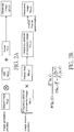
- Fig. 2A is a schematic diagram that illustrates an image generation process and an image recovery process of the image shooting apparatus 100.
- Fig. 2B is a formula that illustrates a Wiener filter.
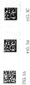
- Fig. 3A to fig. 3C are explanatory diagrams about a relationship between a recovery-purpose PSF and precision of a recovered image.
- Fig. 3A is a recovered image with high precision.
- Fig. 3B is a recovered image with artifacts.
- Fig. 3C is a recovered image with blurs.
- the so-called artifact refers to data errors (error) or signal deformation generated in an observation or analysis phase.
- an observed image g(x, y) is obtained according to an original image f(x, y) and a PSF.
- a power spectrum Fr(u, v) of a recovered image is obtained by multiplying a power spectrum (power spectrum) G(u, v), after Fourier transformation (Fourier transformation), of the observed image by a power spectrum W(u, v) of the Wiener filter, and then a recovered image fr(x, y) is obtained by performing inverse Fourier transformation on the power spectrum Fr(u, v) of the recovered image.
- the Wiener filter is used as one example of multiple image recovery methods, and is widely used (for example, with reference to patent document 2).
- the Wiener filter is an inverse filter (inverse filter) that minimizes an error between the recovered image and the original image, and may be represented by using the formula shown in fig. 2B .
- H represents Fourier transformation of a PSF.
- Sf and Sn are power spectrum distributions on the original image f and noise n on the image.
- An image recovery result depends on precision of H, that is, depends on a degree of similarity between the recovery-purpose PSF and a PSF that is actually applied to the original image.
- the recovered image with high precision shown in fig. 3A is a recovered image obtained when a recovery filter generated by using an appropriate PSF is used, and more particular, when the recovery-purpose PSF is approximately consistent with the PSF actually applied to the original image.
- the recovered image with artifacts shown in fig. 3B is a recovered image obtained when a recovery filter generated by using an inappropriate PSF is used, and more particular, when the recovery-purpose PSF has a power spectrum higher than that of the PSF actually applied to the original image, thereby generating over-exposure state, caused by over-correction, of a code periphery.
- the recovered image with blurs shown in fig. 3C is a recovered image obtained when a recovery filter generated by using an inappropriate PSF is used, and more particular, when the recovery-purpose PSF has a power spectrum lower than that of the PSF actually applied to the original image.
- Fig. 4 is a block diagram that illustrates composition of an image recovery processing portion 150A.
- Fig. 5 is an explanatory diagram of a manufacturing relevant principle of a recovery filter in the image recovery processing portion 150A.
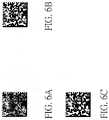
- Fig. 6A to fig. 6C are explanatory diagrams of middle candidate images.
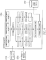
- the image recovery processing portion 150A includes: an image buffer memory 152, configured to receive image data from the image shooting element 220; a recovery filter storage memory 154, configured to store pre-calculated recovery filters; a recovery filter processing portion 153, configured to perform processing on the recovery filters by using the image data received by the image buffer memory 152 and the recovery filters stored in the recovery filter storage memory 154; and an image comment portion 155, configured to comment on a recovered image processed by the recovery filter processing portion 153, and send same to a recovered image buffer memory 159.
- the PSF corresponding to the image shooting distance is used by means of offline processing; recovery filters are separately manufactured by using the method of the Wiener filter, and are pre-stored in the recovery filter storage memory 154.
- the processing may also be set to be performed by executing an image shooting program written into a program memory of a computer.
- the image shooting program may also be provided by a recording medium, for example, a compact disk read-only memory (Compact Disc Read-Only Memory, CD-ROM) that records the image shooting program, or a universal serial bus (Universal Serial Bus, USB) memory, or a network.
- a recording medium for example, a compact disk read-only memory (Compact Disc Read-Only Memory, CD-ROM) that records the image shooting program, or a universal serial bus (Universal Serial Bus, USB) memory, or a network.
- CD-ROM Compact Disc Read-Only Memory
- USB Universal Serial Bus
- the middle candidate images are obtained by performing recovery on a photographed original blurred image by using different recovery filters prepared in advance according to distances.
- Fig. 6A is an example in which a blurred middle candidate image is left due to insufficient correction.
- Fig. 6B is an example in which correction on blurs can be performed appropriately, and no middle candidate image on a level (level) of artifacts occurs.
- Fig. 6C shows an example in which over-exposed middle candidate images with artifacts are generated due to over-correction, which can correct blurs.
- Fig. 7 is a block diagram that illustrates composition of the image comment portion 155 included in the image recovery processing portion 150A shown in fig. 4 .
- the image comment portion 155 performs image sharpness operation 155a and image artifact comment 155b on the middle candidate images received from a middle candidate image buffer memory 156, and then performs synthetic judgment 155c, uses a highest rated middle candidate image as a recovery processing result, and sends same to the recovered image buffer memory 159.
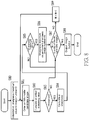
- Fig. 8 is a flowchart of processing in an image comment portion 155.
- a sharpness maximum value (MAX) and an image number are reset as 0 for initialization (step S80).
- An Nth middle candidate image is entered (step S81), and calculation of an artifact evaluating value is executed (step S82).
- step S83 Whether the artifact evaluating value is greater than a threshold is determined (step S83); if the result is no (NO), step S87 is entered.
- step S83 If the result of the determining of step S83 is yes (YES), then after sharpness calculation is performed (step S84), whether the calculated sharpness is greater than a current sharpness MAX value is determined (step S85); if the result is no (NO), whether unprocessed middle candidate images are left is determined (step S87).
- step S85 If the result of the determining of step S85 is yes (YES), then the sharpness MAX is updated as the current sharpness, and a value of a counter N at the moment is added to the image number.
- step S87 Whether the value of the counter N is equal to a quantity of the middle candidate images is determined (step S87); if the result of the determining is yes (YES), then processing on all middle candidate images is completed, and therefore the processing ends with entering of the image number at the moment (step S88).
- step S87 If the result of the determining of step S87 is no (NO), then unprocessed middle candidate images are left, and therefore after 1 is added to the value of the counter N (step S89), step S81 is returned to for repeated processing.
- Fig. 9 shows a modified example of processing in the image comment portion 155, and is a flowchart of parallel processing of using three middle candidate images as input images and performing concretization.
- the middle candidate images respectively correspond to fig. 6A to fig. 6C . Further, detailed description of each step of the processing is omitted.
- the following represents an example of a sharpness calculation result of middle candidate images.
- a point sharpness value of a distance a is 0.973596 (pts sharpness value is 0.973596).
- a point sharpness value of a distance b is 1.161603 (pts sharpness value is 1.161603).
- a point sharpness value of a distance c is 1.183418 (pts sharpness value is 1.183418).
- the following represents an example of an artifact determining result. If a threshold T is not reached, the result is 1 (no artifact); and if the result exceeds the threshold T, the result is 0 (an artifact is generated).
- a result of the foregoing content is that: an image in which an artifact is generated is excluded, and an image with a highest sharpness is selected. That is, a highest rated image is as follows.
- the point sharpness value of the distance b is 1.161603 (pts sharpness value is 1.161603).
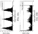
- Fig. 10A and fig. 10B are explanatory diagrams of a principle of artifact comments of an image.
- Fig. 10A is a histogram of image brightness values of a recovered image generally without artifacts.
- Fig. 10B is a histogram of image brightness values of a recovered image with artifacts.
- an horizontal axis represents pixel brightness values; a range of brightness values of 8-bit data is 0 to 255; and a vertical axis represents a quantity of pixels having each brightness value (pixel number (pixel number)).
- pixel number pixel number
- Fig. 11 is a flowchart that illustrates entire image sharpness operation.
- step S111 when the recovered image is entered, first, brightness values are standardized into a range of 0 to 1 (step S111). In standardization of image brightness values, the following formula is used.
- Converted brightness value (brightness value before conversion-minimum value of brightness before conversion)/(maximum value of brightness before conversion-minimum value of brightness before conversion)
- sharpnesses are calculated (step S113), and sharpness values are output.
- the non-patent document 2 provides a profile (image clarity (Image Clarity)) comment index of an image sharpness: a measurement point sharpness (Point sharpness).
- image clarity Image Clarity
- Point sharpness a measurement point sharpness
- the problem is improved by standardizing image brightness values, and automatically extracting a strong edge.
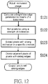
- Fig. 12 is a flowchart that illustrates a strong edge extraction method.
- a brightness edge generated by means of a Sobel (Sobel) filter is calculated (step S121).
- pixels are sorted according to a strength of inclination (step S 122).
- pixels with strong inclination in a specific direction are extracted (step S123). For example, when a photographed object enters horizontally or vertically on an image, a direction of inclination is considerably limited. Pixels whose inclination increases due to noise may be excluded by means of the judgment.
- step S124 adjacent pixels of pixels with strong edges are deleted (step S124). If a particular pixel is determined to have a strong edge, processing is performed by determining that pixels at nearby eight points (a 3 ⁇ 3 area) do not have strong edges.
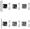
- Fig. 13A to fig. 13F are diagrams of blurred images respectively shot at an accurate focus location and at a location separated from the accurate focus location in a comparative example, a recovered image of an existing method, and a recovered image of the invention.
- the image in the left column corresponds to the accurate focus location
- the image in the right column corresponds to the location separated from the accurate focus location.
- Fig. 13A and fig. 13B are photographed blurred images.
- a profile of the recovered image at the location separated from the accurate focus location shown in fig. 13F does not decrease as such.
- an image with an optimal profile is selected without having to perform distance derivation, and therefore, even if the location is separated from the accurate focus location, a result similar to recovery precision at the accurate focus location is also obtained.
- an optical system in which PSFs change due to image height may also apply processing the same as the foregoing processing in a case in which the PSFs are known although the PSFs change, so as to obtain the same effect.
- sharpness calculation is performed by automatically extracting strong edge points on an entire image.
- it is set to comment on some images of images, for example, a code image or a pupil detection image, of pre-known objects.
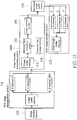
- Fig. 14 is a block diagram that illustrates composition of an image recovery processing portion 150B of an image shooting apparatus of the implementation manner 2 of the invention. Further, the image recovery processing portion 150B corresponds to the image recovery processing portion 150A of the implementation manner 1 (with reference to fig. 4 ).
- an image area designation 157 is supplemented between an image buffer memory 152 and a recovery filter processing portion 153B, and a photographed object edge designation 158 on an image comment portion 155B is supplemented. Further, with the supplement of the image area designation 157 and the photographed object edge designation 158, a portion of processed content of a recovery filter processing portion 153 of the image recovery processing portion 150A and a portion of processed content of an image comment portion 155 of the image recovery processing portion 150A are respectively modified so as to form the recovery filter processing portion 153B and the image comment portion 155B.
- a processing speed may be further accelerated by means of area definition of an image, threshold adjustment of a direction of inclination, or manual edge point designation. Because undesired areas are excluded, false detection and the like can be reduced.
- high-precision recovery may also be performed on only a portion of an image as long as the composition and processing flow of the implementation manner 1 are followed. For example, it is effective only in cases, for example, where a central portion or a peripheral portion in a photographed image is used as a photographed object.
- RGB Red Green Blue
- Fig. 15 is a block diagram that illustrates a main portion, different from implementation manner 1, in an image shooting apparatus of implementation manner 3 of the invention.
- Fig. 16A and fig. 16B are block diagrams that exemplify a general RGB image recovery method.
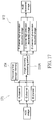
- Fig. 17 is a block diagram that illustrates an RGB image recovery method of implementation manner 3.
- an RGB image decomposition portion 171 is supplemented between an image shooting element 120 and an image recovery processing portion 150A, and an RGB image synthetic portion 172 is supplemented in front of a recovered image buffer memory 159.
- an optimal PSF is separately obtained by means of an image sharpness, so as to obtain a high-precision recovered image, thereby obtaining a synthetic RGB recovered image with higher precision.
- the invention is not limited to the R, G, and B channels only, for example, an infrared radiation (Infrared Radiation, IR) channel may also be supplemented.
- IR Infrared Radiation
- Fig. 18 is a block diagram that illustrates composition of an image recovery processing portion 150C of an image shooting apparatus of implementation manner 4 of the invention.
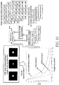
- Fig. 19 is an explanatory diagram of a manufacturing relevant principle of a recovery filter, and the like in the image recovery processing portion 150C.
- Fig. 20A is a block diagram that illustrates composition of an image comment portion 155C included in the image recovery processing portion 150C shown in fig. 18 .
- Fig. 20B is a block diagram that illustrates composition of a synthetic judgment 155Cc included in the image comment portion 155C of fig. 20A .
- an order of a recovery filter processing portion 153C and the image comment portion 155C is changed. Further, with the order change, a portion of processed content of a recovery filter processing portion 153 of the image recovery processing portion 150A, a portion of processed content of a recovery filter storage memory 154 of the image recovery processing portion 150A, and a portion of processed content of an image comment portion 155 of the image recovery processing portion 150A are respectively modified so as to form the recovery filter processing portion 153C, a recovery filter storage memory 154C, and the image comment portion 155C.
- the synthetic judgment 155Cc is to perform sharpness value comparison 155Cc1 based on a result of the image sharpness operation 155Ca, and recovery filters and standard registration images and image sharpnesses corresponding thereto stored in the recovery filter storage memory 154C, and a recovery filter 155Cc2 is selected.
- the standard registration images are blurred images before recovery corresponding to image shooting distances.
- the standard registration images have different blur degrees, and therefore calculated image sharpnesses are also different.
- a method for the synthetic judgment is to compare sharpnesses of photographed images with sharpnesses of the standard registration images stored in the recovery filter storage memory after the sharpnesses of photographed images are calculated in an online manner. Because the image sharpnesses and recovery filters are prepared in pairs, subsequently, a recovery filter corresponding to a closest image sharpness is used to perform recovery.
Landscapes
- Engineering & Computer Science (AREA)
- Multimedia (AREA)
- Signal Processing (AREA)
- Physics & Mathematics (AREA)
- General Physics & Mathematics (AREA)
- Theoretical Computer Science (AREA)
- Software Systems (AREA)
- Computer Vision & Pattern Recognition (AREA)
- Image Processing (AREA)
- Studio Devices (AREA)
- Facsimile Image Signal Circuits (AREA)
- Image Analysis (AREA)
Abstract
Description
- The invention relates to an image shooting apparatus, an image shooting method, an image shooting program, and a recording medium that records the image shooting program, in particular, to an image shooting apparatus and an image shooting method that extend a depth of field by recovering a blurred image, an image shooting program, and a recording medium that records the image shooting program.
- Previously, in special image shooting apparatuses that extend depths of field, for example, by means of wavefront coding (Wavefront Coding, WFC) of optical apparatuses, image recovery needs to a be performed in a particular design range.
- However, if an image shooting distance is separated from a focus location, then a point spread function (PSF: Point spread function, which changes slightly every particular distance) actually applied to an original image deviates from a PSF used for image recovery (using a fixed PSF at the focus location), and therefore maintenance of recovery precision the same as the focus location cannot be implemented. That is, the PSF actually applied to the original image is not fixed due to the image shooting distance, and therefore profile deterioration of a recovered image is generated.
- In
patent document 1 orpatent document 2, a distance is calculated by using a distance detection sensor or multiple image shooting portions, and recovery processing is performed based on PSF data corresponding to each distance obtained by rough estimation. - In
patent document 3, a recovery filter that minimizes a mean square error of a frequency domain is designed in consideration of all PSFs corresponding to multiple defocusing locations. - In addition,
non-patent document 1 discloses a technology called "auto focus (auto focus, AF)" carried in digital cameras that start to be sold by Panasonic (Panasonic) Corporation since April, 2014. In the technology, a depth from defocus (Depth from Defocus, DFD) of a distance is calculated based on analysis according to a blur quantity; after a distance from two images to a photographed object is calculated, a blur model is derived to make a focus image. - Non-patent
document 2 discloses calculation of sharpnesses of images. -
- [Patent document 1]
JP Patent Publication No. 2011-120309 - [Patent document 2]
JP Patent Publication No. 2013-162369 - [Patent document 3]
JP Patent Publication No. 2015-005933 -
- [Non-patent document 1] "Comprehensive List of Panasonic (Panasonic) Digital Cameras 2015/Autumn and Winter", Panasonic Corporation, September, 2015, p. 21
- [Non-patent document 2] Research of Measurement for Digital Image Definition, WANG HongNan, et al., Journal of Image and Graphics (Research of Measurement for Digital Image Definition, WANG HongNan, ..., etc, Journal of Image and Graphics), vol. 9, no. 7, 2004
- However, in the prior art disclosed by
patent document 1 orpatent document 2, for each photographed object included in data of each photographed image, if distance information cannot be correctly derived, then accurate PSF data cannot be used, and therefore optimal recovery processing cannot be performed. Therefore, the problem of cost raise due to a distance detection sensor or multiple image shooting portions needed by calculation of an image shooting distance exists. - In addition, in the prior art disclosed in
patent document 3, because average processing is performed, distance information is not needed. However, the following problem exists, that is, due to PSF data differences at multiple locations, even if optimal recovery processing in the sense of a mean square error is performed, the precision is also poor compared with a recovery result obtained by using a PSF corresponding to an image shooting distance. - In view of such a problem of the prior art, an objective of the invention lies in providing an image shooting apparatus and an image shooting method that obtain a recovered image with high precision by using an optimal PSF without deriving an image shooting distance of a photographed object, an image shooting program, and a recording medium that records the program.
- To achieve the objective, the image shooting apparatus of the invention is characterized by including: an optical system, including one or more than one lenses or the lens and an optical element; an image shooting element, configured at a location further to the rear of the optical system; an image recovery processing portion, configured to perform image processing and recovery processing on image data obtained by the image shooting element; and a recovered image output portion, configured to output an image recovered by the image recovery processing portion; and the image recovery processing portion includes: a recovery filter storage portion, configured to store multiple recovery filters pre-manufactured by using multiple point spread functions (PSF) corresponding to multiple different distances; a recovery filter processing portion, configured to obtain multiple middle candidate images respectively recovered by using the multiple recovery filters according to the image data; and an image comment portion, configured to separately comment on profiles of the multiple candidate images to output an optimal middle candidate image as a recovery processing result.
- Herein, an objective of the optical system lies in extending a depth of field, as long as the PSF is used to perform recovery. The lens may be either a spherical lens or a non-spherical lens, or a suitable combination may be performed in a case in which there are multiple lenses. The optical element, for example, may be a light diffusion plate, a phase plate, or a diffraction grating. However, the invention is not limited thereto.
- The image recovery processing portion may further include: an image area designation portion, configured to designate an image area, used as an object, in the recovery filter processing portion; and an excluded area designation portion, configured to designate an area, which should be excluded from the object by the image comment portion. In addition, the image recovery processing portion may also synthesize recovered images categorized by color signals for the color signals. In addition, the image recovery processing portion may also include a frequency-time filter, an image-space filter, and a time-space filter, for example, a Wiener (Wiener) filter or a finite impulse response (Finite Impulse Response, FIR) filter manufactured by patterns, incident to the image shooting element by means of diffusion, of a point image function.
- In addition, the image shooting apparatus of the invention is characterized by including: an optical system, including one or more than one lenses or the lens and an optical element; an image shooting element, configured at a location further to the rear of the optical system; an image recovery processing portion, configured to perform image processing and recovery processing on image data obtained by the image shooting element; and a recovered image output portion, configured to output an image recovered by the image recovery processing portion; and the image recovery processing portion includes: a recovery filter storage portion, configured to store standard registration images and image sharpnesses corresponding thereto and multiple recovery filters pre-manufactured by using multiple point spread functions corresponding to multiple different distances; and an image comment portion, configured to select a recovery filter corresponding to a closest image sharpness from the recovery filter storage portion based on image sharpnesses obtained by commenting on a profile of the image data; and a recovery filter processing portion, configured to obtain a recovered image by using the selected recovery filter.
- In addition, the image shooting method of the invention is characterized by including: an image shooting process: photographing a photographed object; and an image recovery processing process: performing image processing and recovery processing on image data obtained in the image shooting process; and the image recovery processing process includes: a recovery filter storage process: storing multiple recovery filters pre-manufactured by using multiple point spread functions corresponding to multiple different distances; a recovery filter processing process: obtaining multiple middle candidate images respectively recovered by using the multiple recovery filters according to the image data; and an image comment process: separately commenting on profiles of the multiple candidate images to output an optimal middle candidate image as a recovery processing result.
- In addition, the image shooting method of the invention is characterized by including: an image shooting process: photographing a photographed object; and an image recovery processing process: performing image processing and recovery processing on image data obtained in the image shooting process; and the image recovery processing process includes: a recovery filter storage process: storing standard registration images and image sharpnesses corresponding thereto and multiple recovery filters pre-manufactured by using multiple point spread functions corresponding to multiple different distances; and an image comment process: selecting a recovery filter corresponding to a closest image sharpness based on image sharpnesses obtained by commenting on a profile of the image data; and a recovery filter processing process: obtaining a recovered image by using the selected recovery filter.
- Or the image shooting program of the invention is characterized by enabling a computer to execute the image shooting method.
- According to the image shooting program formed in this way, the image shooting method of the invention may be implemented by using a computer that can execute a program.
- Or the recording medium that records the image shooting program of the invention is a computer readable recording medium, characterized by recording the image shooting program.
- According to the recording medium that records the image shooting program formed in this way, the image shooting method of the invention can be easily implemented in various scenarios or environments, and the recording medium can be provided at a low lost, thereby improving usefulness of the image shooting method of the invention.
- By means of the image shooting apparatus of the invention, a recovered image with high precision may be obtained by using an optimal point spread function without cost raise due to parts needed by derivation of an image shooting distance of a photographed object.
- According to the image recovery method of the invention, a recovered image with high precision may be obtained by using an optimal point spread function without deriving an image shooting distance of a photographed object.
- According to the image shooting program of the invention, the image shooting method of the invention may be implemented by using a computer that can execute a program.
- According to the recording medium that records the image shooting program of the invention, the image shooting method of the invention can be easily implemented in various scenarios or environments, and the recording medium can be provided at a low lost, thereby improving usefulness of the image shooting method of the invention.
- The accompanying drawings are included to provide a further understanding of the invention, and are incorporated in and constitute a part of this specification. The drawings illustrate embodiments of the invention and, together with the description, serve to explain the principles of the invention.
-
Fig. 1 is a block diagram that illustrates composition of animage shooting apparatus 100 ofimplementation manner 1 of the invention. -
Fig. 2A is a schematic diagram that illustrates an image generation process and an image recovery process of animage shooting apparatus 100.Fig. 2B is a formula that illustrates a Wiener filter. -
Fig. 3A to fig. 3C are explanatory diagrams about a relationship between a recovery-purpose PSF and precision of a recovered image.Fig. 3A is a recovered image with high precision.Fig. 3B is a recovered image with artifacts (Artifact).Fig. 3C is a recovered image with blurs. -
Fig. 4 is a block diagram that illustrates composition of an imagerecovery processing portion 150. -
Fig. 5 is an explanatory diagram of a manufacturing relevant principle of a recovery filter in an imagerecovery processing portion 150A. -
Fig. 6A to fig. 6C are explanatory diagrams of middle candidate images. -
Fig. 7 is a block diagram that illustrates composition of animage comment portion 155 included in an imagerecovery processing portion 150A shown infig. 4 . -
Fig. 8 is a flowchart of processing in animage comment portion 155. -
Fig. 9 shows a modified example of processing in animage comment portion 155, and is a flowchart of parallel processing of using three middle candidate images as input images and performing concretization. -
Fig. 10A and fig. 10B are explanatory diagrams of a principle of artifact comments of an image.Fig. 10A is a histogram of image brightness values of a recovered image generally without artifacts.Fig. 10B is a histogram of image brightness values of a recovered image with artifacts. -
Fig. 11 is a flowchart that illustrates entire image sharpness operation. -
Fig. 12 is a flowchart that illustrates a strong edge extraction method. -
Fig. 13A to fig. 13F are diagrams of blurred images respectively shot at an accurate focus location and at a location separated from the accurate focus location in a comparative example, a recovered image of an existing method, and a recovered image of the invention. -
Fig. 14 is a block diagram that illustrates composition of an imagerecovery processing portion 150B of an image shooting apparatus ofimplementation manner 2 of the invention. -
Fig. 15 is a block diagram that illustrates a main portion, different fromimplementation manner 1, in an image shooting apparatus ofimplementation manner 3 of the invention. -
Fig. 16A and fig. 16B are block diagrams that exemplify a general RGB image recovery method. -
Fig. 17 is a block diagram that illustrates an RGB image recovery method ofimplementation manner 3. -
Fig. 18 is a block diagram that illustrates composition of an imagerecovery processing portion 150C of an image shooting apparatus of implementation manner 4 of the invention. -
Fig. 19 is an explanatory diagram of a manufacturing relevant principle of a recovery filter, and the like in an imagerecovery processing portion 150C. -
Fig. 20A is a block diagram that illustrates composition of animage comment portion 155C included in an imagerecovery processing portion 150C shown infig. 18 .Fig. 20B is a block diagram that illustrates composition of a synthetic judgment 155Cc included in animage comment portion 155C offig. 20A . - Reference will now be made in detail to the present preferred embodiments of the invention, examples of which are illustrated in the accompanying drawings. Wherever possible, the same reference numbers are used in the drawings and the description to refer to the same or like parts.
-
Fig. 1 is a block diagram that illustrates composition of animage shooting apparatus 100 ofimplementation manner 1 of the invention. Further, in the following description, a side of incidence of light to anoptical system 110 is called "front surface" (the left side in the drawing), and a side of emission of light from theoptical system 110 is called "rear surface" (the right side in the drawing). - As shown in
fig. 1 , theimage shooting apparatus 100 includes: anoptical system 110; animage shooting element 120, configured at a location further to the rear of theoptical system 110; an analog to digital (analog to digital, A/D)converter 130, configured to convert an analog signal output from theimage shooting element 120 into a digital signal; animage processing portion 140, which includes an original (RAW)image memory 141 and aconvolution operation portion 142, and performs image processing on image data of the digital signal output from the A/D converter 130; an imagerecovery processing portion 150, which includes adeconvolution operation portion 151, and performs recovery processing on image data obtained after the image processing is performed by theimage processing portion 140; and a recoveredimage output portion 160, configured to output an image recovered by the imagerecovery processing portion 150. - The
optical system 110 includes alens 112a to alens 112c, adiaphragm 113 configured directly in front of asecond lens 112b, and alight diffusion plate 115 configured at a location further to the front of thefirst lens 112a. - Herein, the
first lens 112a and thethird lens 112c are set as convex lenses, and thesecond lens 112b is set as a concave lens. However, the invention is not limited to this combination, as long as a quantity of entire lenses is two or more than two, and the quantity is not necessarily limited to three. In addition, the lens may be either a spherical lens or a non-spherical lens. A suitable combination may be performed in a case in which there are multiple lenses. Thelight diffusion plate 115 is an optical element, which may also be another optical element, for example, a phase plate, or a diffraction element. A location where the optical element is configured is not limited to the location further to the front of thefirst lens 112a, and may be, for example, a location behind thethird lens 112c. - The
diaphragm 113 is an aperture diaphragm, but a location where thediaphragm 113 is configured is not necessarily limited to the location shown in the drawing. - A front surface of the
light diffusion plate 115 is a plane, and a rear surface thereof becomes adiffusion surface 115b. A location where thelight diffusion plate 115 is configured is not necessarily limited to the location shown in the drawing, and may be a location behind thethird lens 112c. - The
image shooting element 120 may be a charge coupled device (charge coupled device, CCD) sensor, a complementary metal oxide semiconductor (complementary metal oxide semiconductor, CMOS) sensor, a metal oxide semiconductor (metal oxide semiconductor, MOS) sensor, and the like, but the invention is not limited thereto. When theimage shooting element 120 can directly output a digital signal rather than an analog signal, the A/D converter 130 may be omitted. - The
image processing portion 140 and the imagerecovery processing portion 150 do not necessarily need to be independent, and may also be combined together. - In the
deconvolution operation portion 151 of the imagerecovery processing portion 150, for example, operation may also be performed by using a Wiener filter, or an FIR filter, but the invention is not limited to these filters. -
Fig. 2A is a schematic diagram that illustrates an image generation process and an image recovery process of theimage shooting apparatus 100.Fig. 2B is a formula that illustrates a Wiener filter.Fig. 3A to fig. 3C are explanatory diagrams about a relationship between a recovery-purpose PSF and precision of a recovered image.Fig. 3A is a recovered image with high precision.Fig. 3B is a recovered image with artifacts.Fig. 3C is a recovered image with blurs. Further, the so-called artifact refers to data errors (error) or signal deformation generated in an observation or analysis phase. - As shown in
fig. 2A , in a spatial area, an observed image g(x, y) is obtained according to an original image f(x, y) and a PSF. In a frequency domain, a power spectrum Fr(u, v) of a recovered image is obtained by multiplying a power spectrum (power spectrum) G(u, v), after Fourier transformation (Fourier transformation), of the observed image by a power spectrum W(u, v) of the Wiener filter, and then a recovered image fr(x, y) is obtained by performing inverse Fourier transformation on the power spectrum Fr(u, v) of the recovered image. - The Wiener filter is used as one example of multiple image recovery methods, and is widely used (for example, with reference to patent document 2). In short, the Wiener filter is an inverse filter (inverse filter) that minimizes an error between the recovered image and the original image, and may be represented by using the formula shown in
fig. 2B . Herein, H represents Fourier transformation of a PSF. Sf and Sn are power spectrum distributions on the original image f and noise n on the image. - An image recovery result depends on precision of H, that is, depends on a degree of similarity between the recovery-purpose PSF and a PSF that is actually applied to the original image.
- The recovered image with high precision shown in
fig. 3A is a recovered image obtained when a recovery filter generated by using an appropriate PSF is used, and more particular, when the recovery-purpose PSF is approximately consistent with the PSF actually applied to the original image. - The recovered image with artifacts shown in
fig. 3B is a recovered image obtained when a recovery filter generated by using an inappropriate PSF is used, and more particular, when the recovery-purpose PSF has a power spectrum higher than that of the PSF actually applied to the original image, thereby generating over-exposure state, caused by over-correction, of a code periphery. - The recovered image with blurs shown in
fig. 3C is a recovered image obtained when a recovery filter generated by using an inappropriate PSF is used, and more particular, when the recovery-purpose PSF has a power spectrum lower than that of the PSF actually applied to the original image. -
Fig. 4 is a block diagram that illustrates composition of an imagerecovery processing portion 150A.Fig. 5 is an explanatory diagram of a manufacturing relevant principle of a recovery filter in the imagerecovery processing portion 150A.Fig. 6A to fig. 6C are explanatory diagrams of middle candidate images. - As shown in
fig. 4 , the imagerecovery processing portion 150A includes: animage buffer memory 152, configured to receive image data from the image shooting element 220; a recoveryfilter storage memory 154, configured to store pre-calculated recovery filters; a recoveryfilter processing portion 153, configured to perform processing on the recovery filters by using the image data received by theimage buffer memory 152 and the recovery filters stored in the recoveryfilter storage memory 154; and animage comment portion 155, configured to comment on a recovered image processed by the recoveryfilter processing portion 153, and send same to a recoveredimage buffer memory 159. - A summary of overall processing in the image
recovery processing portion 150A is stated below (also with reference tofig. 5 ). - 1. Pre-manufacturing recovery filters respectively by using multiple PSFs corresponding to different distances, and pre-storing the recovery filters.
- 2. Photographing an image, and obtaining an input image.
- 3. Performing recovery processing on the input image respectively by using the stored recovery filters corresponding to the multiple PSFs. Obtaining multiple middle candidate images in this way.
- 4. Respectively commenting on profiles of the multiple middle candidate images by using two indexes: image sharpnesses and image artifacts.
- 5. Outputting a highest rated middle candidate image as a recovery processing result.
- As shown in
fig. 5 , when an image shooting distance is changed, Fourier transformation of a PSF corresponding thereto, that is, an absolute value of a modulation transfer function (modulation transfer function, MTF) also changes. - The PSF corresponding to the image shooting distance is used by means of offline processing; recovery filters are separately manufactured by using the method of the Wiener filter, and are pre-stored in the recovery
filter storage memory 154. - Further, the processing may also be set to be performed by executing an image shooting program written into a program memory of a computer. The image shooting program may also be provided by a recording medium, for example, a compact disk read-only memory (Compact Disc Read-Only Memory, CD-ROM) that records the image shooting program, or a universal serial bus (Universal Serial Bus, USB) memory, or a network.
- As shown in
fig. 6A to fig. 6C , the middle candidate images are obtained by performing recovery on a photographed original blurred image by using different recovery filters prepared in advance according to distances.Fig. 6A is an example in which a blurred middle candidate image is left due to insufficient correction.Fig. 6B is an example in which correction on blurs can be performed appropriately, and no middle candidate image on a level (level) of artifacts occurs.Fig. 6C shows an example in which over-exposed middle candidate images with artifacts are generated due to over-correction, which can correct blurs. -
Fig. 7 is a block diagram that illustrates composition of theimage comment portion 155 included in the imagerecovery processing portion 150A shown infig. 4 . - As show in
fig. 7 , theimage comment portion 155 performsimage sharpness operation 155a andimage artifact comment 155b on the middle candidate images received from a middle candidateimage buffer memory 156, and then performssynthetic judgment 155c, uses a highest rated middle candidate image as a recovery processing result, and sends same to the recoveredimage buffer memory 159. -
Fig. 8 is a flowchart of processing in animage comment portion 155. - As shown in
fig. 8 , a sharpness maximum value (MAX) and an image number are reset as 0 for initialization (step S80). - An Nth middle candidate image is entered (step S81), and calculation of an artifact evaluating value is executed (step S82).
- Whether the artifact evaluating value is greater than a threshold is determined (step S83); if the result is no (NO), step S87 is entered.
- If the result of the determining of step S83 is yes (YES), then after sharpness calculation is performed (step S84), whether the calculated sharpness is greater than a current sharpness MAX value is determined (step S85); if the result is no (NO), whether unprocessed middle candidate images are left is determined (step S87).
- If the result of the determining of step S85 is yes (YES), then the sharpness MAX is updated as the current sharpness, and a value of a counter N at the moment is added to the image number.
- Whether the value of the counter N is equal to a quantity of the middle candidate images is determined (step S87); if the result of the determining is yes (YES), then processing on all middle candidate images is completed, and therefore the processing ends with entering of the image number at the moment (step S88).
- If the result of the determining of step S87 is no (NO), then unprocessed middle candidate images are left, and therefore after 1 is added to the value of the counter N (step S89), step S81 is returned to for repeated processing.
-
Fig. 9 shows a modified example of processing in theimage comment portion 155, and is a flowchart of parallel processing of using three middle candidate images as input images and performing concretization. The middle candidate images respectively correspond tofig. 6A to fig. 6C . Further, detailed description of each step of the processing is omitted. - The following represents an example of a sharpness calculation result of middle candidate images.
- A point sharpness value of a distance a is 0.973596 (pts sharpness value is 0.973596).
- A point sharpness value of a distance b is 1.161603 (pts sharpness value is 1.161603).
- A point sharpness value of a distance c is 1.183418 (pts sharpness value is 1.183418).
- In addition, the following represents an example of an artifact determining result. If a threshold T is not reached, the result is 1 (no artifact); and if the result exceeds the threshold T, the result is 0 (an artifact is generated).
- The distance a 1
- The
distance b 1 - The
distance c 0 - A result of the foregoing content is that: an image in which an artifact is generated is excluded, and an image with a highest sharpness is selected. That is, a highest rated image is as follows.
- The point sharpness value of the distance b is 1.161603 (pts sharpness value is 1.161603).
-
Fig. 10A and fig. 10B are explanatory diagrams of a principle of artifact comments of an image.Fig. 10A is a histogram of image brightness values of a recovered image generally without artifacts.Fig. 10B is a histogram of image brightness values of a recovered image with artifacts. - As shown in the histograms, an horizontal axis represents pixel brightness values; a range of brightness values of 8-bit data is 0 to 255; and a vertical axis represents a quantity of pixels having each brightness value (pixel number (pixel number)). Compared with the recovered image generally without artifacts, in the recovered image with artifacts, peak values can be clearly seen at two sites: a maximum value (MAX) (a brightness value=255) and a minimum value (MIN) (a brightness value=0) of the histogram. If a sum of pixel numbers having brightness values ranging from 250 to 255 is greater than the fixed threshold T, then it is determined that an artifact exists.
-
Fig. 11 is a flowchart that illustrates entire image sharpness operation. - As shown in
fig. 11 , when the recovered image is entered, first, brightness values are standardized into a range of 0 to 1 (step S111). In standardization of image brightness values, the following formula is used. - Converted brightness value=(brightness value before conversion-minimum value of brightness before conversion)/(maximum value of brightness before conversion-minimum value of brightness before conversion)
- Secondly, "strong edge extraction" is executed (description is provided below with reference to
fig. 12 ) (step S112). - Finally, sharpnesses are calculated (step S113), and sharpness values are output.
- The
non-patent document 2 provides a profile (image clarity (Image Clarity)) comment index of an image sharpness: a measurement point sharpness (Point sharpness). However, because direct calculation needs to be performed on all pixels of a to-be-commented input image, robustness (robustness) is lost in the following three cases. - When photographed objects are different, for example, comparison between scenery and human images cannot be performed.
- Even if the same image content exists, comparison cannot be performed in a case in which brightnesses are different.
- Even if the image content is the same, comparison cannot be performed in a case in which noise levels are different.
- In the image sharpness operation shown in
fig. 11 , the problem is improved by standardizing image brightness values, and automatically extracting a strong edge. -
Fig. 12 is a flowchart that illustrates a strong edge extraction method. - As shown in
fig. 12 , first, a brightness edge generated by means of a Sobel (Sobel) filter is calculated (step S121). - Secondly, pixels are sorted according to a strength of inclination (step S 122).
- Then, to extract an exact strong edge, pixels with strong inclination in a specific direction are extracted (step S123). For example, when a photographed object enters horizontally or vertically on an image, a direction of inclination is considerably limited. Pixels whose inclination increases due to noise may be excluded by means of the judgment.
- In addition, to reduce effects of, for example, nonuniformity of image brightness values, to extract edge pixels without faculas in the entire photographed object as uniformly as possible, adjacent pixels of pixels with strong edges are deleted (step S124). If a particular pixel is determined to have a strong edge, processing is performed by determining that pixels at nearby eight points (a 3×3 area) do not have strong edges.
-
Fig. 13A to fig. 13F are diagrams of blurred images respectively shot at an accurate focus location and at a location separated from the accurate focus location in a comparative example, a recovered image of an existing method, and a recovered image of the invention. The image in the left column corresponds to the accurate focus location, and the image in the right column corresponds to the location separated from the accurate focus location. -
Fig. 13A and fig. 13B are photographed blurred images. - In the existing method for performing recovery based on a PSF at the accurate focus location, compared with the recovered image at the accurate focus location shown in
fig. 13C , a profile of the recovered image at the location separated from the accurate focus location shown infig. 13D obviously decreases. - On the contrary, according to the invention that performs recovery based on an optimal PSF obtained by means of image sharpnesses, compared with the recovered image at the accurate focus location shown in
fig. 13E , a profile of the recovered image at the location separated from the accurate focus location shown infig. 13F does not decrease as such. - According to the invention, an image with an optimal profile is selected without having to perform distance derivation, and therefore, even if the location is separated from the accurate focus location, a result similar to recovery precision at the accurate focus location is also obtained.
- Further, in cases in which a motion blur (motion blur) exists, that is, a photographed object jitters, or within an image shooting range or a field range, an optical system in which PSFs change due to image height may also apply processing the same as the foregoing processing in a case in which the PSFs are known although the PSFs change, so as to obtain the same effect.
- In the
implementation manner 1, sharpness calculation is performed by automatically extracting strong edge points on an entire image. In theimplementation manner 2, it is set to comment on some images of images, for example, a code image or a pupil detection image, of pre-known objects. -
Fig. 14 is a block diagram that illustrates composition of an imagerecovery processing portion 150B of an image shooting apparatus of theimplementation manner 2 of the invention. Further, the imagerecovery processing portion 150B corresponds to the imagerecovery processing portion 150A of the implementation manner 1 (with reference tofig. 4 ). - As shown in
fig. 14 , in the imagerecovery processing portion 150B, compared with the imagerecovery processing portion 150A of the implementation manner 1 (with reference tofig. 4 ), animage area designation 157 is supplemented between animage buffer memory 152 and a recoveryfilter processing portion 153B, and a photographedobject edge designation 158 on animage comment portion 155B is supplemented. Further, with the supplement of theimage area designation 157 and the photographedobject edge designation 158, a portion of processed content of a recoveryfilter processing portion 153 of the imagerecovery processing portion 150A and a portion of processed content of animage comment portion 155 of the imagerecovery processing portion 150A are respectively modified so as to form the recoveryfilter processing portion 153B and theimage comment portion 155B. - A processing speed may be further accelerated by means of area definition of an image, threshold adjustment of a direction of inclination, or manual edge point designation. Because undesired areas are excluded, false detection and the like can be reduced.
- In addition, according to the use purpose, high-precision recovery may also be performed on only a portion of an image as long as the composition and processing flow of the
implementation manner 1 are followed. For example, it is effective only in cases, for example, where a central portion or a peripheral portion in a photographed image is used as a photographed object. - In the
implementation manner 1 or theimplementation manner 2, black and white images are processed. However, color images are used as processing objects in theimplementation manner 3. For example, if an image is a red green blue (Red Green Blue, RGB) image, then a high-precision recovered image processed according to an RGB channel is synthesized, and therefore the same effect can also be achieved for the RGB image. -
Fig. 15 is a block diagram that illustrates a main portion, different fromimplementation manner 1, in an image shooting apparatus ofimplementation manner 3 of the invention.Fig. 16A and fig. 16B are block diagrams that exemplify a general RGB image recovery method.Fig. 17 is a block diagram that illustrates an RGB image recovery method ofimplementation manner 3. - As shown in
fig. 15 , in theimplementation manner 3, an RGBimage decomposition portion 171 is supplemented between animage shooting element 120 and an imagerecovery processing portion 150A, and an RGB imagesynthetic portion 172 is supplemented in front of a recoveredimage buffer memory 159. - In a case of the general RGB image recovery method shown in
fig. 16A or fig. 16B , recovery is performed on a converted brightness image/RGB channel based on one PSF. However, originally, PSFs of channels R, G, and B are subtly different from each other, and therefore if recovery is performed by using only one PSF, the effect that the PSFs of the channels R, G, and B are different is generated. - On the contrary, in the
implementation manner 3, as shown infig. 17 , in the channels R, G, and B, an optimal PSF is separately obtained by means of an image sharpness, so as to obtain a high-precision recovered image, thereby obtaining a synthetic RGB recovered image with higher precision. - Further, the invention is not limited to the R, G, and B channels only, for example, an infrared radiation (Infrared Radiation, IR) channel may also be supplemented.
- In the foregoing implementation manners, image comments upon multiple middle candidate images that are respectively recovered by using multiple recovery filters are provided. In the implementation manner 4, it is set that comments are made based on a blurred image before recovery and then a recovery filter is selected.
-
Fig. 18 is a block diagram that illustrates composition of an imagerecovery processing portion 150C of an image shooting apparatus of implementation manner 4 of the invention.Fig. 19 is an explanatory diagram of a manufacturing relevant principle of a recovery filter, and the like in the imagerecovery processing portion 150C.Fig. 20A is a block diagram that illustrates composition of animage comment portion 155C included in the imagerecovery processing portion 150C shown infig. 18 .Fig. 20B is a block diagram that illustrates composition of a synthetic judgment 155Cc included in theimage comment portion 155C offig. 20A . - As shown in
fig. 18 , in the imagerecovery processing portion 150C, compared with the imagerecovery processing portion 150A (with reference tofig. 4 ) of theimplementation manner 1, an order of a recoveryfilter processing portion 153C and theimage comment portion 155C is changed. Further, with the order change, a portion of processed content of a recoveryfilter processing portion 153 of the imagerecovery processing portion 150A, a portion of processed content of a recoveryfilter storage memory 154 of the imagerecovery processing portion 150A, and a portion of processed content of animage comment portion 155 of the imagerecovery processing portion 150A are respectively modified so as to form the recoveryfilter processing portion 153C, a recoveryfilter storage memory 154C, and theimage comment portion 155C. - A summary of overall processing in the image
recovery processing portion 150C is stated below (also with reference tofig. 19 ). - 1. Pre-using multiple PSFs corresponding to multiple different distances to manufacture, in pairs, recovery filters and standard registration images and image sharpnesses corresponding thereto. Further, the standard registration images refer to representative blurred images photographed at various distances.
- 2. Photographing an image, and obtaining an input image.
- 3. For the input image, commenting on profiles of the blurred images by using an index of image sharpnesses.
- 4. Selecting a recovery filter paired with an image sharpnesses closest to values of image sharpnesses corresponding to the standard registration images as a recovery filter for input image recovery.
- 5. Performing recovery processing by using the recovery filter, and outputting same as a recovery processing result.
- As shown in
fig. 20A , in theimage comment portion 155C, after image sharpness operation 155Ca on image data received from animage buffer memory 152 is performed, synthetic judgment 155Cc is performed, and a recovery processing result is sent to arecovery filter buffer 159C. - The synthetic judgment 155Cc, as shown in
fig. 20B is to perform sharpness value comparison 155Cc1 based on a result of the image sharpness operation 155Ca, and recovery filters and standard registration images and image sharpnesses corresponding thereto stored in the recoveryfilter storage memory 154C, and a recovery filter 155Cc2 is selected. - The standard registration images (multiple) are blurred images before recovery corresponding to image shooting distances. The standard registration images have different blur degrees, and therefore calculated image sharpnesses are also different.
- Different from the
implementation manner 1, more than recovery filters should be prepared in advance in an offline manner. Image sharpnesses corresponding thereto are also prepared in pairs in advance. - A method for the synthetic judgment is to compare sharpnesses of photographed images with sharpnesses of the standard registration images stored in the recovery filter storage memory after the sharpnesses of photographed images are calculated in an online manner. Because the image sharpnesses and recovery filters are prepared in pairs, subsequently, a recovery filter corresponding to a closest image sharpness is used to perform recovery.
Claims (9)
- An image shooting apparatus (100) comprising:an optical system (110), comprising one or more than one lenses (112a, 112b, 112c) or the lens (112a, 112b, 112c) and an optical element (115);an image shooting element (120), configured at a location further to the rear of the optical system (110);an image recovery processing portion (150, 150A, 150B, 150C), configured to perform image processing and recovery processing on image data obtained by the image shooting element (120); anda recovered image output portion (160), configured to output an image recovered by the image recovery processing portion (150, 150A, 150B, 150C);wherein the image recovery processing portion (150, 150A, 150B, 150C) comprises:a recovery filter storage portion (154, 154C), configured to store multiple recovery filters (155Cc2) pre-manufactured by using multiple point spread functions corresponding to multiple different distances;a recovery filter processing portion (153, 153B, 153C), configured to obtain multiple middle candidate images respectively recovered by using the multiple recovery filters (155Cc2) according to the image data; andan image comment portion (155, 155B, 155C), configured to separately comment on profiles of the multiple candidate images to output an optimal middle candidate image as a recovery processing result.
- The image shooting apparatus (100) according to claim 1, wherein
the image recovery processing portion (150, 150A, 150B, 150C) further comprises:an image area designation portion (157), configured to designate an image area, used as an object, in the recovery filter processing portion (153, 153B, 153C); andan excluded area designation portion, configured to designate an area, which should be excluded from the object by the image comment portion (155, 155B, 155C). - The image shooting apparatus (100) according to claim 1 or 2, wherein the image recovery processing portion (150, 150A, 150B, 150C) synthesizes recovered images categorized by color signals for each of the color signals.
- An image shooting apparatus (100), comprising:an optical system (110), comprising one or more than one lenses (112a, 112b, 112c) or the lens (112a, 112b, 112c) and an optical element (115);an image shooting element (120), configured at a location further to the rear of the optical system (110);an image recovery processing portion (150, 150A, 150B, 150C), configured to perform image processing and recovery processing on image data obtained by the image shooting element (120); anda recovered image output portion (160), configured to output an image recovered by the image recovery processing portion (150, 150A, 150B, 150C);wherein the image recovery processing portion (150, 150A, 150B, 150C) comprises:a recovery filter storage portion (154, 154C), configured to store standard registration images and image sharpnesses corresponding thereto and multiple recovery filters (155Cc2) pre-manufactured by using multiple point spread functions corresponding to multiple different distances; andan image comment portion (155, 155B, 155C), configured to select a recovery filter (155Cc2) corresponding to a closest image sharpness from the recovery filter storage portion (154, 154C) based on image sharpnesses obtained by commenting on a profile of the image data; anda recovery filter processing portion (153, 153B, 153C), configured to obtain a recovered image by using the selected recovery filter (155Cc2).
- The image shooting apparatus (100) according to any one of claim 1, wherein:the image recovery processing portion (150, 150A, 150B, 150C) comprises a Wiener filter or an FIR filter manufactured by patterns, incident to the image shooting element (120) by means of diffusion, of a point image function.
- An image shooting method (S80, S81, S82, S83, S84, S85, S86, S87, S88, S89, S111, S112, S113, S121, S122, S123, S124) comprising:an image shooting process: photographing a photographed object; andan image recovery processing process: performing image processing and recovery processing on image data obtained in the image shooting process;wherein the image recovery processing process comprises:a recovery filter storage process: storing multiple recovery filters pre-manufactured by using multiple point spread functions corresponding to multiple different distances;a recovery filter processing process: obtaining multiple middle candidate images respectively recovered by using the multiple recovery filters according to the image data; andan image comment process: separately commenting on profiles of the multiple candidate images to output an optimal middle candidate image as a recovery processing result.
- An image shooting method (S80, S81, S82, S83, S84, S85, S86, S87, S88, S89, S111, S112, S113, S121, S122, S123, S124) comprising:an image shooting process: photographing a photographed object; andan image recovery processing process: performing image processing and recovery processing on image data obtained in the image shooting process; andthe image recovery processing process comprises:a recovery filter storage process: storing standard registration images and image sharpnesses corresponding thereto and multiple recovery filters pre-manufactured by using multiple point spread functions corresponding to multiple different distances; andan image comment process: selecting a recovery filter corresponding to a closest image sharpness based on image sharpnesses obtained by commenting on a profile of the image data; anda recovery filter processing process: obtaining a recovered image by using the selected recovery filter.
- An image shooting program, wherein a computer is enabled to execute the image shooting method (S80, S81, S82, S83, S84, S85, S86, S87, S88, S89, S111, S112, S113, S121, S122, S123, S124) according to claim 6 or 7.
- A recording medium, wherein the image shooting program according to claim 8 is recorded.
Applications Claiming Priority (1)
| Application Number | Priority Date | Filing Date | Title |
|---|---|---|---|
| JP2016010094A JP6578960B2 (en) | 2016-01-21 | 2016-01-21 | IMAGING DEVICE, IMAGING METHOD, IMAGING PROGRAM, AND RECORDING MEDIUM CONTAINING THE IMAGING PROGRAM |
Publications (2)
| Publication Number | Publication Date |
|---|---|
| EP3209014A1 true EP3209014A1 (en) | 2017-08-23 |
| EP3209014B1 EP3209014B1 (en) | 2020-01-29 |
Family
ID=57914634
Family Applications (1)
| Application Number | Title | Priority Date | Filing Date |
|---|---|---|---|
| EP16204384.8A Active EP3209014B1 (en) | 2016-01-21 | 2016-12-15 | Image shooting apparatus, image shooting method, image shooting program, and recording medium that records the image shooting program |
Country Status (4)
| Country | Link |
|---|---|
| US (1) | US10217194B2 (en) |
| EP (1) | EP3209014B1 (en) |
| JP (1) | JP6578960B2 (en) |
| CN (1) | CN106993111B (en) |
Families Citing this family (3)
| Publication number | Priority date | Publication date | Assignee | Title |
|---|---|---|---|---|
| CN110191287B (en) * | 2019-06-28 | 2021-05-11 | Oppo广东移动通信有限公司 | Focusing method and device, electronic equipment and computer readable storage medium |
| CN110691180A (en) * | 2019-08-13 | 2020-01-14 | 中国人民解放军国防科技大学 | Photoelectric imaging system capable of inhibiting laser back reflection |
| JP7554083B2 (en) * | 2020-09-18 | 2024-09-19 | 株式会社Screenホールディングス | IMAGE PROCESSING METHOD, IMAGE PROCESSING APPARATUS AND IMAGING APPARATUS |
Citations (6)
| Publication number | Priority date | Publication date | Assignee | Title |
|---|---|---|---|---|
| JP2011120309A (en) | 2011-03-22 | 2011-06-16 | Kyocera Corp | Imaging device |
| US20110242373A1 (en) * | 2010-03-31 | 2011-10-06 | Canon Kabushiki Kaisha | Image processing apparatus, image pickup apparatus, image processing method, and program for performing image restoration |
| JP2013162369A (en) | 2012-02-07 | 2013-08-19 | Sharp Corp | Imaging device |
| JP2015005933A (en) | 2013-06-21 | 2015-01-08 | 株式会社リコー | Imaging apparatus, imaging system, and imaging method |
| WO2015090611A1 (en) * | 2013-12-20 | 2015-06-25 | Sony Corporation | Apparatus and optical system including an optical element |
| US20150317776A1 (en) * | 2013-02-15 | 2015-11-05 | Fujifilm Corporation | Image processing device and image capture device |
Family Cites Families (15)
| Publication number | Priority date | Publication date | Assignee | Title |
|---|---|---|---|---|
| JP4749985B2 (en) * | 2006-09-28 | 2011-08-17 | 京セラ株式会社 | Imaging device, manufacturing apparatus and manufacturing method thereof |
| TWI399524B (en) * | 2009-02-20 | 2013-06-21 | Ind Tech Res Inst | Method and apparatus for extracting scenery depth imformation |
| JP5409112B2 (en) * | 2009-05-21 | 2014-02-05 | キヤノン株式会社 | Image processing apparatus and method |
| JP2011135563A (en) * | 2009-11-30 | 2011-07-07 | Canon Inc | Image capturing apparatus, and image processing method |
| JP5868076B2 (en) * | 2011-08-31 | 2016-02-24 | キヤノン株式会社 | Image processing apparatus and image processing method |
| JP6056160B2 (en) * | 2012-03-09 | 2017-01-11 | カシオ計算機株式会社 | Automatic focusing device, automatic focusing method and program |
| US9014504B2 (en) * | 2012-05-31 | 2015-04-21 | Apple Inc. | Systems and methods for highlight recovery in an image signal processor |
| US9332239B2 (en) * | 2012-05-31 | 2016-05-03 | Apple Inc. | Systems and methods for RGB image processing |
| US9142012B2 (en) * | 2012-05-31 | 2015-09-22 | Apple Inc. | Systems and methods for chroma noise reduction |
| DE112013004435T5 (en) * | 2013-03-28 | 2015-06-11 | Fujifilm Corp. | Image processing apparatus, image pickup apparatus, image processing method, program and recording medium |
| JP5851655B2 (en) * | 2013-04-26 | 2016-02-03 | 富士フイルム株式会社 | Image processing apparatus, imaging apparatus, image processing method, and program |
| JP5903528B2 (en) * | 2013-07-29 | 2016-04-13 | 富士フイルム株式会社 | Imaging apparatus and image processing method |
| WO2015064264A1 (en) * | 2013-10-31 | 2015-05-07 | 富士フイルム株式会社 | Image processing device, image capture device, parameter generating method, image processing method, and program |
| CN106165390B (en) * | 2014-03-28 | 2019-06-28 | 富士胶片株式会社 | Image processing device, photographing device, and image processing method |
| JP6512893B2 (en) * | 2015-03-26 | 2019-05-15 | キヤノン株式会社 | IMAGE PROCESSING APPARATUS, IMAGING APPARATUS, IMAGE PROCESSING METHOD, AND COMPUTER PROGRAM |
-
2016
- 2016-01-21 JP JP2016010094A patent/JP6578960B2/en active Active
- 2016-12-15 EP EP16204384.8A patent/EP3209014B1/en active Active
- 2016-12-16 CN CN201611175006.8A patent/CN106993111B/en active Active
- 2016-12-20 US US15/384,324 patent/US10217194B2/en active Active
Patent Citations (6)
| Publication number | Priority date | Publication date | Assignee | Title |
|---|---|---|---|---|
| US20110242373A1 (en) * | 2010-03-31 | 2011-10-06 | Canon Kabushiki Kaisha | Image processing apparatus, image pickup apparatus, image processing method, and program for performing image restoration |
| JP2011120309A (en) | 2011-03-22 | 2011-06-16 | Kyocera Corp | Imaging device |
| JP2013162369A (en) | 2012-02-07 | 2013-08-19 | Sharp Corp | Imaging device |
| US20150317776A1 (en) * | 2013-02-15 | 2015-11-05 | Fujifilm Corporation | Image processing device and image capture device |
| JP2015005933A (en) | 2013-06-21 | 2015-01-08 | 株式会社リコー | Imaging apparatus, imaging system, and imaging method |
| WO2015090611A1 (en) * | 2013-12-20 | 2015-06-25 | Sony Corporation | Apparatus and optical system including an optical element |
Non-Patent Citations (2)
| Title |
|---|
| "Comprehensive List of Panasonic (Panasonic) Digital Cameras 2015/Autumn and Winter", September 2015, PANASONIC CORPORATION, pages: 21 |
| WANG HONGNAN ET AL., JOURNAL OF IMAGE AND GRAPHICS (RESEARCH OF MEASUREMENT FOR DIGITAL IMAGE DEFINITION, vol. 9, no. 7, 2004 |
Also Published As
| Publication number | Publication date |
|---|---|
| US10217194B2 (en) | 2019-02-26 |
| CN106993111A (en) | 2017-07-28 |
| EP3209014B1 (en) | 2020-01-29 |
| US20170213325A1 (en) | 2017-07-27 |
| JP2017130848A (en) | 2017-07-27 |
| CN106993111B (en) | 2019-12-10 |
| JP6578960B2 (en) | 2019-09-25 |
Similar Documents
| Publication | Publication Date | Title |
|---|---|---|
| US8159552B2 (en) | Apparatus and method for restoring image based on distance-specific point spread function | |
| CN102209245B (en) | Image processing apparatus, image pickup apparatus and image processing method | |
| US9883095B2 (en) | Focus adjusting device and focus adjusting program with control unit to guide a light image based upon detected distributions | |
| US10395348B2 (en) | Image pickup apparatus, image processing apparatus, and control method of image pickup apparatus | |
| US9373183B2 (en) | Removing an occlusion from an image | |
| EP3371741B1 (en) | Focus detection | |
| US20160239977A1 (en) | Image processing apparatus, imaging apparatus, depth measuring apparatus and image processing method | |
| US12395745B2 (en) | Image processing apparatus and method, and image capturing apparatus | |
| US20160080727A1 (en) | Depth measurement apparatus, imaging apparatus, and depth measurement method | |
| EP3018529B1 (en) | Image processing apparatus and method for image processing | |
| US20150054978A1 (en) | Imaging apparatus, its control method, and storage medium | |
| EP3015892A1 (en) | Image pickup device and image pickup method | |
| JP6491581B2 (en) | Image processing apparatus, control method therefor, and program | |
| EP3209014B1 (en) | Image shooting apparatus, image shooting method, image shooting program, and recording medium that records the image shooting program | |
| US11080873B2 (en) | Image processing apparatus, image capturing apparatus, image processing method, and storage medium | |
| US10015386B2 (en) | Focus control apparatus, image capturing apparatus, interchangeable lens, focus control method, and storage medium storing focus control program | |
| US10929960B2 (en) | Method and image processing device for detecting a portion of an image | |
| JP2015177510A (en) | camera system, image processing method and program | |
| US20190094656A1 (en) | Imaging apparatus and control method of the same | |
| WO2012076992A1 (en) | Auto-focus image system | |
| US11115582B2 (en) | Imaging control apparatus, imaging apparatus, and recording medium | |
| US20180027195A1 (en) | Image processing apparatus and a control method for controlling the image processing apparatus | |
| JP2017182668A (en) | Data processing apparatus, imaging apparatus, and data processing method | |
| JP2008042227A (en) | Imaging device | |
| US9094600B2 (en) | Image capturing apparatus and control method therefor |
Legal Events
| Date | Code | Title | Description |
|---|---|---|---|
| PUAI | Public reference made under article 153(3) epc to a published international application that has entered the european phase |
Free format text: ORIGINAL CODE: 0009012 |
|
| STAA | Information on the status of an ep patent application or granted ep patent |
Free format text: STATUS: REQUEST FOR EXAMINATION WAS MADE |
|
| 17P | Request for examination filed |
Effective date: 20161215 |
|
| AK | Designated contracting states |
Kind code of ref document: A1 Designated state(s): AL AT BE BG CH CY CZ DE DK EE ES FI FR GB GR HR HU IE IS IT LI LT LU LV MC MK MT NL NO PL PT RO RS SE SI SK SM TR |
|
| AX | Request for extension of the european patent |
Extension state: BA ME |
|
| RBV | Designated contracting states (corrected) |
Designated state(s): AL AT BE BG CH CY CZ DE DK EE ES FI FR GB GR HR HU IE IS IT LI LT LU LV MC MK MT NL NO PL PT RO RS SE SI SK SM TR |
|
| STAA | Information on the status of an ep patent application or granted ep patent |
Free format text: STATUS: EXAMINATION IS IN PROGRESS |
|
| 17Q | First examination report despatched |
Effective date: 20190123 |
|
| GRAP | Despatch of communication of intention to grant a patent |
Free format text: ORIGINAL CODE: EPIDOSNIGR1 |
|
| STAA | Information on the status of an ep patent application or granted ep patent |
Free format text: STATUS: GRANT OF PATENT IS INTENDED |
|
| INTG | Intention to grant announced |
Effective date: 20190723 |
|
| GRAS | Grant fee paid |
Free format text: ORIGINAL CODE: EPIDOSNIGR3 |
|
| GRAA | (expected) grant |
Free format text: ORIGINAL CODE: 0009210 |
|
| STAA | Information on the status of an ep patent application or granted ep patent |
Free format text: STATUS: THE PATENT HAS BEEN GRANTED |
|
| AK | Designated contracting states |
Kind code of ref document: B1 Designated state(s): AL AT BE BG CH CY CZ DE DK EE ES FI FR GB GR HR HU IE IS IT LI LT LU LV MC MK MT NL NO PL PT RO RS SE SI SK SM TR |
|
| REG | Reference to a national code |
Ref country code: GB Ref legal event code: FG4D |
|
| REG | Reference to a national code |
Ref country code: CH Ref legal event code: EP |
|
| REG | Reference to a national code |
Ref country code: AT Ref legal event code: REF Ref document number: 1229200 Country of ref document: AT Kind code of ref document: T Effective date: 20200215 |
|
| REG | Reference to a national code |
Ref country code: IE Ref legal event code: FG4D |
|
| REG | Reference to a national code |
Ref country code: DE Ref legal event code: R096 Ref document number: 602016028634 Country of ref document: DE |
|
| REG | Reference to a national code |
Ref country code: NL Ref legal event code: MP Effective date: 20200129 |
|
| PG25 | Lapsed in a contracting state [announced via postgrant information from national office to epo] |
Ref country code: RS Free format text: LAPSE BECAUSE OF FAILURE TO SUBMIT A TRANSLATION OF THE DESCRIPTION OR TO PAY THE FEE WITHIN THE PRESCRIBED TIME-LIMIT Effective date: 20200129 Ref country code: NO Free format text: LAPSE BECAUSE OF FAILURE TO SUBMIT A TRANSLATION OF THE DESCRIPTION OR TO PAY THE FEE WITHIN THE PRESCRIBED TIME-LIMIT Effective date: 20200429 Ref country code: PT Free format text: LAPSE BECAUSE OF FAILURE TO SUBMIT A TRANSLATION OF THE DESCRIPTION OR TO PAY THE FEE WITHIN THE PRESCRIBED TIME-LIMIT Effective date: 20200621 Ref country code: FI Free format text: LAPSE BECAUSE OF FAILURE TO SUBMIT A TRANSLATION OF THE DESCRIPTION OR TO PAY THE FEE WITHIN THE PRESCRIBED TIME-LIMIT Effective date: 20200129 |
|
| REG | Reference to a national code |
Ref country code: LT Ref legal event code: MG4D |
|
| PG25 | Lapsed in a contracting state [announced via postgrant information from national office to epo] |
Ref country code: GR Free format text: LAPSE BECAUSE OF FAILURE TO SUBMIT A TRANSLATION OF THE DESCRIPTION OR TO PAY THE FEE WITHIN THE PRESCRIBED TIME-LIMIT Effective date: 20200430 Ref country code: LV Free format text: LAPSE BECAUSE OF FAILURE TO SUBMIT A TRANSLATION OF THE DESCRIPTION OR TO PAY THE FEE WITHIN THE PRESCRIBED TIME-LIMIT Effective date: 20200129 Ref country code: SE Free format text: LAPSE BECAUSE OF FAILURE TO SUBMIT A TRANSLATION OF THE DESCRIPTION OR TO PAY THE FEE WITHIN THE PRESCRIBED TIME-LIMIT Effective date: 20200129 Ref country code: IS Free format text: LAPSE BECAUSE OF FAILURE TO SUBMIT A TRANSLATION OF THE DESCRIPTION OR TO PAY THE FEE WITHIN THE PRESCRIBED TIME-LIMIT Effective date: 20200529 Ref country code: HR Free format text: LAPSE BECAUSE OF FAILURE TO SUBMIT A TRANSLATION OF THE DESCRIPTION OR TO PAY THE FEE WITHIN THE PRESCRIBED TIME-LIMIT Effective date: 20200129 Ref country code: BG Free format text: LAPSE BECAUSE OF FAILURE TO SUBMIT A TRANSLATION OF THE DESCRIPTION OR TO PAY THE FEE WITHIN THE PRESCRIBED TIME-LIMIT Effective date: 20200429 |
|
| PG25 | Lapsed in a contracting state [announced via postgrant information from national office to epo] |
Ref country code: NL Free format text: LAPSE BECAUSE OF FAILURE TO SUBMIT A TRANSLATION OF THE DESCRIPTION OR TO PAY THE FEE WITHIN THE PRESCRIBED TIME-LIMIT Effective date: 20200129 |
|
| PG25 | Lapsed in a contracting state [announced via postgrant information from national office to epo] |
Ref country code: EE Free format text: LAPSE BECAUSE OF FAILURE TO SUBMIT A TRANSLATION OF THE DESCRIPTION OR TO PAY THE FEE WITHIN THE PRESCRIBED TIME-LIMIT Effective date: 20200129 Ref country code: SM Free format text: LAPSE BECAUSE OF FAILURE TO SUBMIT A TRANSLATION OF THE DESCRIPTION OR TO PAY THE FEE WITHIN THE PRESCRIBED TIME-LIMIT Effective date: 20200129 Ref country code: DK Free format text: LAPSE BECAUSE OF FAILURE TO SUBMIT A TRANSLATION OF THE DESCRIPTION OR TO PAY THE FEE WITHIN THE PRESCRIBED TIME-LIMIT Effective date: 20200129 Ref country code: RO Free format text: LAPSE BECAUSE OF FAILURE TO SUBMIT A TRANSLATION OF THE DESCRIPTION OR TO PAY THE FEE WITHIN THE PRESCRIBED TIME-LIMIT Effective date: 20200129 Ref country code: SK Free format text: LAPSE BECAUSE OF FAILURE TO SUBMIT A TRANSLATION OF THE DESCRIPTION OR TO PAY THE FEE WITHIN THE PRESCRIBED TIME-LIMIT Effective date: 20200129 Ref country code: LT Free format text: LAPSE BECAUSE OF FAILURE TO SUBMIT A TRANSLATION OF THE DESCRIPTION OR TO PAY THE FEE WITHIN THE PRESCRIBED TIME-LIMIT Effective date: 20200129 Ref country code: CZ Free format text: LAPSE BECAUSE OF FAILURE TO SUBMIT A TRANSLATION OF THE DESCRIPTION OR TO PAY THE FEE WITHIN THE PRESCRIBED TIME-LIMIT Effective date: 20200129 Ref country code: ES Free format text: LAPSE BECAUSE OF FAILURE TO SUBMIT A TRANSLATION OF THE DESCRIPTION OR TO PAY THE FEE WITHIN THE PRESCRIBED TIME-LIMIT Effective date: 20200129 |
|
| REG | Reference to a national code |
Ref country code: DE Ref legal event code: R097 Ref document number: 602016028634 Country of ref document: DE |
|
| REG | Reference to a national code |
Ref country code: AT Ref legal event code: MK05 Ref document number: 1229200 Country of ref document: AT Kind code of ref document: T Effective date: 20200129 |
|
| PLBE | No opposition filed within time limit |
Free format text: ORIGINAL CODE: 0009261 |
|
| STAA | Information on the status of an ep patent application or granted ep patent |
Free format text: STATUS: NO OPPOSITION FILED WITHIN TIME LIMIT |
|
| 26N | No opposition filed |
Effective date: 20201030 |
|
| PG25 | Lapsed in a contracting state [announced via postgrant information from national office to epo] |
Ref country code: AT Free format text: LAPSE BECAUSE OF FAILURE TO SUBMIT A TRANSLATION OF THE DESCRIPTION OR TO PAY THE FEE WITHIN THE PRESCRIBED TIME-LIMIT Effective date: 20200129 Ref country code: IT Free format text: LAPSE BECAUSE OF FAILURE TO SUBMIT A TRANSLATION OF THE DESCRIPTION OR TO PAY THE FEE WITHIN THE PRESCRIBED TIME-LIMIT Effective date: 20200129 |
|
| PG25 | Lapsed in a contracting state [announced via postgrant information from national office to epo] |
Ref country code: SI Free format text: LAPSE BECAUSE OF FAILURE TO SUBMIT A TRANSLATION OF THE DESCRIPTION OR TO PAY THE FEE WITHIN THE PRESCRIBED TIME-LIMIT Effective date: 20200129 Ref country code: PL Free format text: LAPSE BECAUSE OF FAILURE TO SUBMIT A TRANSLATION OF THE DESCRIPTION OR TO PAY THE FEE WITHIN THE PRESCRIBED TIME-LIMIT Effective date: 20200129 |
|
| REG | Reference to a national code |
Ref country code: CH Ref legal event code: PL |
|
| GBPC | Gb: european patent ceased through non-payment of renewal fee |
Effective date: 20201215 |
|
| PG25 | Lapsed in a contracting state [announced via postgrant information from national office to epo] |
Ref country code: MC Free format text: LAPSE BECAUSE OF FAILURE TO SUBMIT A TRANSLATION OF THE DESCRIPTION OR TO PAY THE FEE WITHIN THE PRESCRIBED TIME-LIMIT Effective date: 20200129 |
|
| REG | Reference to a national code |
Ref country code: BE Ref legal event code: MM Effective date: 20201231 |
|
| PG25 | Lapsed in a contracting state [announced via postgrant information from national office to epo] |
Ref country code: FR Free format text: LAPSE BECAUSE OF NON-PAYMENT OF DUE FEES Effective date: 20201231 Ref country code: LU Free format text: LAPSE BECAUSE OF NON-PAYMENT OF DUE FEES Effective date: 20201215 Ref country code: IE Free format text: LAPSE BECAUSE OF NON-PAYMENT OF DUE FEES Effective date: 20201215 |
|
| PG25 | Lapsed in a contracting state [announced via postgrant information from national office to epo] |
Ref country code: CH Free format text: LAPSE BECAUSE OF NON-PAYMENT OF DUE FEES Effective date: 20201231 Ref country code: LI Free format text: LAPSE BECAUSE OF NON-PAYMENT OF DUE FEES Effective date: 20201231 Ref country code: GB Free format text: LAPSE BECAUSE OF NON-PAYMENT OF DUE FEES Effective date: 20201215 |
|
| PG25 | Lapsed in a contracting state [announced via postgrant information from national office to epo] |
Ref country code: TR Free format text: LAPSE BECAUSE OF FAILURE TO SUBMIT A TRANSLATION OF THE DESCRIPTION OR TO PAY THE FEE WITHIN THE PRESCRIBED TIME-LIMIT Effective date: 20200129 Ref country code: MT Free format text: LAPSE BECAUSE OF FAILURE TO SUBMIT A TRANSLATION OF THE DESCRIPTION OR TO PAY THE FEE WITHIN THE PRESCRIBED TIME-LIMIT Effective date: 20200129 Ref country code: CY Free format text: LAPSE BECAUSE OF FAILURE TO SUBMIT A TRANSLATION OF THE DESCRIPTION OR TO PAY THE FEE WITHIN THE PRESCRIBED TIME-LIMIT Effective date: 20200129 |
|
| PG25 | Lapsed in a contracting state [announced via postgrant information from national office to epo] |
Ref country code: MK Free format text: LAPSE BECAUSE OF FAILURE TO SUBMIT A TRANSLATION OF THE DESCRIPTION OR TO PAY THE FEE WITHIN THE PRESCRIBED TIME-LIMIT Effective date: 20200129 Ref country code: AL Free format text: LAPSE BECAUSE OF FAILURE TO SUBMIT A TRANSLATION OF THE DESCRIPTION OR TO PAY THE FEE WITHIN THE PRESCRIBED TIME-LIMIT Effective date: 20200129 |
|
| PG25 | Lapsed in a contracting state [announced via postgrant information from national office to epo] |
Ref country code: BE Free format text: LAPSE BECAUSE OF NON-PAYMENT OF DUE FEES Effective date: 20201231 |
|
| REG | Reference to a national code |
Ref country code: DE Ref legal event code: R079 Ref document number: 602016028634 Country of ref document: DE Free format text: PREVIOUS MAIN CLASS: H04N0005232000 Ipc: H04N0023600000 |
|
| PGFP | Annual fee paid to national office [announced via postgrant information from national office to epo] |
Ref country code: DE Payment date: 20251222 Year of fee payment: 10 |