EP3208915B1 - Electric blower - Google Patents
Electric blower Download PDFInfo
- Publication number
- EP3208915B1 EP3208915B1 EP17155112.0A EP17155112A EP3208915B1 EP 3208915 B1 EP3208915 B1 EP 3208915B1 EP 17155112 A EP17155112 A EP 17155112A EP 3208915 B1 EP3208915 B1 EP 3208915B1
- Authority
- EP
- European Patent Office
- Prior art keywords
- centrifugal fan
- sleeve
- electric blower
- diffuser
- hole
- Prior art date
- Legal status (The legal status is an assumption and is not a legal conclusion. Google has not performed a legal analysis and makes no representation as to the accuracy of the status listed.)
- Not-in-force
Links
Images


Classifications
-
- F—MECHANICAL ENGINEERING; LIGHTING; HEATING; WEAPONS; BLASTING
- F04—POSITIVE - DISPLACEMENT MACHINES FOR LIQUIDS; PUMPS FOR LIQUIDS OR ELASTIC FLUIDS
- F04D—NON-POSITIVE-DISPLACEMENT PUMPS
- F04D29/00—Details, component parts, or accessories
- F04D29/05—Shafts or bearings, or assemblies thereof, specially adapted for elastic fluid pumps
- F04D29/056—Bearings
-
- F—MECHANICAL ENGINEERING; LIGHTING; HEATING; WEAPONS; BLASTING
- F04—POSITIVE - DISPLACEMENT MACHINES FOR LIQUIDS; PUMPS FOR LIQUIDS OR ELASTIC FLUIDS
- F04D—NON-POSITIVE-DISPLACEMENT PUMPS
- F04D29/00—Details, component parts, or accessories
- F04D29/02—Selection of particular materials
- F04D29/023—Selection of particular materials especially adapted for elastic fluid pumps
-
- F—MECHANICAL ENGINEERING; LIGHTING; HEATING; WEAPONS; BLASTING
- F04—POSITIVE - DISPLACEMENT MACHINES FOR LIQUIDS; PUMPS FOR LIQUIDS OR ELASTIC FLUIDS
- F04D—NON-POSITIVE-DISPLACEMENT PUMPS
- F04D29/00—Details, component parts, or accessories
- F04D29/05—Shafts or bearings, or assemblies thereof, specially adapted for elastic fluid pumps
- F04D29/051—Axial thrust balancing
-
- F—MECHANICAL ENGINEERING; LIGHTING; HEATING; WEAPONS; BLASTING
- F16—ENGINEERING ELEMENTS AND UNITS; GENERAL MEASURES FOR PRODUCING AND MAINTAINING EFFECTIVE FUNCTIONING OF MACHINES OR INSTALLATIONS; THERMAL INSULATION IN GENERAL
- F16C—SHAFTS; FLEXIBLE SHAFTS; ELEMENTS OR CRANKSHAFT MECHANISMS; ROTARY BODIES OTHER THAN GEARING ELEMENTS; BEARINGS
- F16C35/00—Rigid support of bearing units; Housings, e.g. caps, covers
- F16C35/04—Rigid support of bearing units; Housings, e.g. caps, covers in the case of ball or roller bearings
- F16C35/06—Mounting or dismounting of ball or roller bearings; Fixing them onto shaft or in housing
- F16C35/07—Fixing them on the shaft or housing with interposition of an element
- F16C35/077—Fixing them on the shaft or housing with interposition of an element between housing and outer race ring
-
- H—ELECTRICITY
- H02—GENERATION; CONVERSION OR DISTRIBUTION OF ELECTRIC POWER
- H02K—DYNAMO-ELECTRIC MACHINES
- H02K5/00—Casings; Enclosures; Supports
- H02K5/04—Casings or enclosures characterised by the shape, form or construction thereof
- H02K5/16—Means for supporting bearings, e.g. insulating supports or means for fitting bearings in the bearing-shields
- H02K5/167—Means for supporting bearings, e.g. insulating supports or means for fitting bearings in the bearing-shields using sliding-contact or spherical cap bearings
- H02K5/1675—Means for supporting bearings, e.g. insulating supports or means for fitting bearings in the bearing-shields using sliding-contact or spherical cap bearings radially supporting the rotary shaft at only one end of the rotor
-
- F—MECHANICAL ENGINEERING; LIGHTING; HEATING; WEAPONS; BLASTING
- F05—INDEXING SCHEMES RELATING TO ENGINES OR PUMPS IN VARIOUS SUBCLASSES OF CLASSES F01-F04
- F05D—INDEXING SCHEME FOR ASPECTS RELATING TO NON-POSITIVE-DISPLACEMENT MACHINES OR ENGINES, GAS-TURBINES OR JET-PROPULSION PLANTS
- F05D2230/00—Manufacture
- F05D2230/20—Manufacture essentially without removing material
- F05D2230/23—Manufacture essentially without removing material by permanently joining parts together
-
- F—MECHANICAL ENGINEERING; LIGHTING; HEATING; WEAPONS; BLASTING
- F05—INDEXING SCHEMES RELATING TO ENGINES OR PUMPS IN VARIOUS SUBCLASSES OF CLASSES F01-F04
- F05D—INDEXING SCHEME FOR ASPECTS RELATING TO NON-POSITIVE-DISPLACEMENT MACHINES OR ENGINES, GAS-TURBINES OR JET-PROPULSION PLANTS
- F05D2260/00—Function
- F05D2260/30—Retaining components in desired mutual position
- F05D2260/36—Retaining components in desired mutual position by a form fit connection, e.g. by interlocking
-
- F—MECHANICAL ENGINEERING; LIGHTING; HEATING; WEAPONS; BLASTING
- F16—ENGINEERING ELEMENTS AND UNITS; GENERAL MEASURES FOR PRODUCING AND MAINTAINING EFFECTIVE FUNCTIONING OF MACHINES OR INSTALLATIONS; THERMAL INSULATION IN GENERAL
- F16C—SHAFTS; FLEXIBLE SHAFTS; ELEMENTS OR CRANKSHAFT MECHANISMS; ROTARY BODIES OTHER THAN GEARING ELEMENTS; BEARINGS
- F16C2226/00—Joining parts; Fastening; Assembling or mounting parts
- F16C2226/30—Material joints
- F16C2226/40—Material joints with adhesive
-
- F—MECHANICAL ENGINEERING; LIGHTING; HEATING; WEAPONS; BLASTING
- F16—ENGINEERING ELEMENTS AND UNITS; GENERAL MEASURES FOR PRODUCING AND MAINTAINING EFFECTIVE FUNCTIONING OF MACHINES OR INSTALLATIONS; THERMAL INSULATION IN GENERAL
- F16C—SHAFTS; FLEXIBLE SHAFTS; ELEMENTS OR CRANKSHAFT MECHANISMS; ROTARY BODIES OTHER THAN GEARING ELEMENTS; BEARINGS
- F16C2360/00—Engines or pumps
- F16C2360/46—Fans, e.g. ventilators
Landscapes
- Engineering & Computer Science (AREA)
- General Engineering & Computer Science (AREA)
- Mechanical Engineering (AREA)
- Power Engineering (AREA)
- Structures Of Non-Positive Displacement Pumps (AREA)
Description
- An embodiment of the present invention relates to an electric blower.
- An electric blower is known that includes a brushless motor equipped with a rotor, a centrifugal fan adapted to rotate along with rotation of a rotating shaft of the rotor, the rotating shaft adapted to integrally rotatably support the rotor and centrifugal fan, a sleeve through which a shaft is passed, at least one of bearing provided in the sleeve and adapted to rotatably support the rotating shaft, and a frame provided with a through hole in which the sleeve is fixed.
US 2013/0004304 A1 discloses an electric blower according to the preamble ofclaim 1.US 2006/181174 discloses an anti-loose device for securing a stator of a motor to a shaft. - In the conventional electric blower, the centrifugal fan, rotating shaft, bearing, and sleeve are assembled beforehand and handled as a whole, it is hereinafter referred to simply as a "rotor component assembly". The sleeve is inserted into the through hole of the frame, and is bonded to the frame with an adhesive. And then, the rotor component assembly is assembled onto the frame. The rotating shaft, the bearing, and the sleeve are inserted into the through hole from an opposite side opposite of the centrifugal fan, which is an end part of the rotor component assembly farther from the centrifugal fan, as an outside diameter of the centrifugal fan is larger than outside diameters of the rotating shaft, bearing, and sleeve.
- When the centrifugal fan rotates, a force directed toward the suction side of the centrifugal fan acts on the rotor component assembly. In other words, when the centrifugal fan rotates, a force tending to pull out the sleeve from the through hole of the frame toward the suction side of the centrifugal fan acts on the sleeve supporting the rotor component assembly on the frame.
- If the force tending to pull out the sleeve from the through hole exceeds adhesive strength of the adhesive, the sleeve will be detached from the through hole, which adhesion between the sleeve and frame is insufficient or the adhesion becomes insufficient due to deterioration of the adhesive. If the sleeve is detached from the through hole, the centrifugal fan might touch a shroud. Then, the electric blower will fall in efficiency or get broken.
- To solve the problems described above, it is an object of the present invention to provide an electric blower that can strongly hold and fix a sleeve onto a frame, and to eventually provide high reliability.
- To achieve the above object, an aspect of the present invention provides, an electric blower according to an embodiment of the present invention including a centrifugal fan, a shaft installed integrally rotatably with the centrifugal fan, a sleeve provided with a recess in an outer circumferential surface, at least one of bearing provided in the sleeve and adapted to rotatably support the shaft, a frame provided with a through hole in which the sleeve is fixed; and a stopper filling up a gap between the frame and the recess and adapted to harden and thereby prevent the sleeve from being detached from the through hole.
- In preferred embodiments of the above aspect, the following modes may be provided.
- It may be desired that the frame includes a cavity connected to the recess.
- It may be desired that the frame includes a second recess connected to the cavity.
- It may be desired that an end of the sleeve that is closer to the centrifugal fan is closer to the centrifugal fan than a mouth of the through hole that is closer to the centrifugal fan.
- It may be desired that the frame is a resin molding, and the stopper is a hardened epoxy adhesive.
-
-
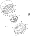
Fig. 1 is an exploded perspective view of an electric blower according to an embodiment of the present invention; -
Fig. 2 is a sectional view of the electric blower according to the embodiment of the present invention; -
Fig. 3 is an enlarged sectional view of a bearing component assembly and its surroundings in the electric blower according to the embodiment of the present invention; -
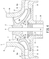
Fig. 4 is an enlarged sectional view of the bearing component assembly and its surroundings in the electric blower according to the embodiment of the present invention; -
Fig. 5 is an enlarged sectional view of the bearing component assembly and its surroundings in the electric blower according to the embodiment of the present invention; -
Fig. 6 is an enlarged sectional view of another example of the bearing component assembly and its surroundings in the electric blower according to the embodiment of the present invention; -
Fig. 7 is an enlarged sectional view of another example of the bearing component assembly and its surroundings in the electric blower according to the embodiment of the present invention; and -
Fig. 8 is an enlarged sectional view of another example of the bearing component assembly and its surroundings in the electric blower according to the embodiment of the present invention. - An embodiment of an electric blower according to the present invention will be described with reference to
Figs. 1 to 8 . - Note that in different drawings, same or equivalent components are denoted by the same reference numerals.
-
Fig. 1 is an exploded perspective view of the electric blower according to the embodiment of the present invention. -
Fig. 2 is a sectional view of the electric blower according to the embodiment of the present invention. - As shown in
Figs. 1 and2 , theelectric blower 1 according to the present embodiment includes a rotor component assembly 3 including acentrifugal fan 2, an electric motor 5 adapted to drive thecentrifugal fan 2, adiffuser 6 adapted to guide a fluid discharged from thecentrifugal fan 2 to the electric motor 5, and ashroud 8 provided with aninlet 7 and adapted to cover thecentrifugal fan 2. Note that the fluid is exclusively a gas, which is air. - The rotor component assembly 3 includes the
centrifugal fan 2, ashaft 9 integrally rotatably fixed to thecentrifugal fan 2, and abearing component assembly 11 adapted to rotatably support theshaft 9 on thediffuser 6. The rotor component assembly 3 is assembled from thecentrifugal fan 2,shaft 9, and bearingcomponent assembly 11 beforehand and handled as a whole. The rotor component assembly 3 is assembled to thediffuser 6 as a whole. - One end of the
shaft 9 is fixed to thecentrifugal fan 2 at one end, and another end of theshaft 9 is connected to the electric motor 5. - The
centrifugal fan 2 includes ahub 12 andplural blades 13 projecting from thehub 12. Thehub 12 has ahole 15 into which thefixed shaft 9 in central part. Thecentrifugal fan 2 is placed upstream of thediffuser 6. - The
bearing component assembly 11 includes asleeve 16 and at least one ofbearing 17 installed in thesleeve 16 and adapted to rotatably support theshaft 9. A pair of thebearings 17 is placed at respective ends of thesleeve 16, being spaced away from each other. Thebearings 17 spaced away from each other supports theshaft 9 properly. Thesleeve 16 surrounds and holds thebearings 17 placed concentrically. - The
shaft 9,bearings 17, andsleeve 16 are made of metallic materials, and particularly, made of ferrous materials. - The electric motor 5 includes a
rotor 18 integrally rotatably fixed to theshaft 9 and astator 19 configured to surround therotor 18 by being fixed to thediffuser 6. The electric motor 5 is placed on a downstream side of thediffuser 6. - The
diffuser 6 also functions as a frame adapted to rotatably support theshaft 9 andcentrifugal fan 2 via thebearing component assembly 11. Thus, thediffuser 6 has a throughhole 21 for use to fix thesleeve 16. Thediffuser 6 holds thestator 19 of the electric motor 5. - The
diffuser 6 is a resin molding, for example, a molding of a Poly Ethylene Terephthalate (PET) resin mixed with glass fiber. Thediffuser 6 includes ahub 22, anouter shell 23 cylindrical in shape and concentric with thehub 22, and pluralaxis direction vanes 25. - The
hub 22 includes acentral part 26 cylindrical in shape and adapted to hold thebearing component assembly 11, anouter ring part 27 adapted to define a passage leading a fluid flowing out of thecentrifugal fan 2 toward the electric motor 5, in conjunction with theouter shell 23, and adisc part 28 extending between thecentral part 26 andouter ring part 27. - A first stepped
part 31 configured to demarcate thecentral part 26 anddisc part 28 from each other is provided on a surface of thehub 22 that faces to thecentrifugal fan 2. The first steppedpart 31 slopes down outward thehub 22, being away from thecentrifugal fan 2. - A second stepped
part 32 configured to demarcate thedisc part 28 andouter ring part 27 from each other is provided on the surface of thehub 22 that faces to thecentrifugal fan 2. - When viewed from the side of the
centrifugal fan 2, there is a cavity on an outer side of the first steppedpart 31, that is, outer peripheral side of thehub 22 of the first steppedpart 31, and on an inner side of the second steppedpart 32, that is, center side of thehub 22 of the second steppedpart 32. A bottom surface of the cavity corresponds to a surface of thedisc part 28 that faces to thecentrifugal fan 2. An outer periphery of a rear shroud of thecentrifugal fan 2 is placed in the cavity. - The through
hole 21 in which thesleeve 16 is fixed is provided in thecentral part 26 of thehub 22. The throughhole 21 holds and fixes the bearingcomponent assembly 11 via thesleeve 16, and rotatably supports theshaft 9 andcentrifugal fan 2. - The
outer shell 23 surrounds theentire hub 22 by being spaced away from thehub 22. - The axis direction vanes 25 have a two-dimensional airfoil section. The axis direction vanes 25 are installed between the
outer shell 23 andhub 22, integrating theouter shell 23 andhub 22. Trailing edges of the axis direction vanes 25 provide a fluid outlet for theelectric blower 1. That is, thediffuser 6 guides the fluid discharged from thecentrifugal fan 2 toward the electric motor 5. - The axis direction vanes 25 define the fluid outlet of the
diffuser 6 between thehub 22 andouter shell 23 via a space serving as a passage. - Note that the
diffuser 6 may be provided with plural radial direction vanes 33 (broken lines). The radial direction vanes 33 are provided in theouter ring part 27, being placed at intervals in a circumferential direction. The radial direction vanes 33 also have a two-dimensional wing section. When thediffuser 6 is provided with the radial direction vanes 33,plural recesses 38a corresponding to the radial direction vanes 33 are provided on an inner surface of athird wall 38 of theshroud 8. The radial direction vanes 33 are fixed to thediffuser 6 by entering therespective recesses 38a. - The
shroud 8 corresponds to a front shroud of thecentrifugal fan 2. Theshroud 8 is provided with awall part 35 adapted to cover those parts of thecentrifugal fan 2 and thediffuser 6. Thewall part 35 is located on an upstream side of thecentrifugal fan 2 and thediffuser 6. Thewall part 35 includes afirst wall 36 cylindrical in shape and provided with theinlet 7 adapted to lead the fluid to thecentrifugal fan 2, asecond wall 37 shaped like a cone and configured to spread gradually along theblades 13 of thecentrifugal fan 2, and thethird wall 38 adapted to close the upstream side of thediffuser 6. - The
inlet 7 is a circular opening serving as a fluid inlet of theelectric blower 1. - The
shroud 8 is bonded and fixed to theouter shell 23 of thediffuser 6 with an adhesive 39. Theshroud 8 covering the upstream side of thecentrifugal fan 2 and thediffuser 6 defines a passage running from the fluid inlet, that is,inlet 7, of theelectric blower 1 to the fluid outlet, that is, trailing edges of the plural axis direction vanes 25. -
Figs. 3 to 5 are enlarged sectional views of the bearing component assembly and its surroundings in the electric blower according to the embodiment of the present invention. - As shown in
Figs. 3 to 5 as well asFig. 2 , thesleeve 16 of theelectric blower 1 according to the embodiment of the present invention has arecess 41 in an outer circumferential surface. - The
recess 41 is provided on an end of thesleeve 16 that is closer to thecentrifugal fan 2. As shown inFig. 2 andFig. 3 , therecess 41 may be a notch opening to the end of thesleeve 16 that is closer to thecentrifugal fan 2. As shown inFig. 4 , therecess 41 may extend like a groove on the outer circumferential surface of thesleeve 16. Also, recesses 41 may be provided at plural locations on the outer circumferential surface of thesleeve 16 discontinuously in the circumferential direction. - The
diffuser 6 has a chamfered,inclined surface 42 on a mouth, that is, an open end of the throughhole 21 that is closer to thecentrifugal fan 2. Theinclined surface 42 is provided inward of the first steppedpart 31 i.e., on the center side of thehub 12. A wedge-shaped cavity is defined between theinclined surface 42 andsleeve 16. The wedge-shaped cavity is approaching thesleeve 16 with increasing distance from thecentrifugal fan 2. The wedge-shaped cavity is connected to therecess 41 on thesleeve 16. - When the
sleeve 16 is placed at a predetermined position of the throughhole 21 in thediffuser 6, at least a portion of therecess 41 that includes a part most distant from thecentrifugal fan 2 is placed in the he wedge-shaped cavity drawn by theinclined surface 42 by remaining more distant from thecentrifugal fan 2 than anend face 26a of thecentral part 26 of thehub 22. - The
electric blower 1 includes astopper 43 filling up a gap between thediffuser 6 and therecess 41 of thesleeve 16 and adapted to harden and thereby prevent thesleeve 16 from being detached from the throughhole 21. - The
stopper 43 is charged into the cavity between theinclined surface 42 of thediffuser 6 and thesleeve 16 and enters therecess 41 of thesleeve 16. Thestopper 43 is, for example, an epoxy adhesive filled into the cavity between theinclined surface 42 andsleeve 16 when thestopper 43 has fluidity before curing. Thehardened stopper 43 is integrated strongly with thediffuser 6 made of resin while entering therecess 41 of thesleeve 16 to function as an anchor and prevent thesleeve 16 from being detached from the throughhole 21. - Note that, when a
recess 45 is provided also on thediffuser 6 as shown inFig. 5 , thestopper 43 can fasten thediffuser 6 andsleeve 16 together more strongly. In that case, it is not necessary that theinclined surface 42 is provided at the mouth of the throughhole 21. In this case, a groove-like space connected to therecess 41 on thesleeve 16 andrecess 45 on thediffuser 6 is defined between thesleeve 16 and thediffuser 6. Thestopper 43 is charged into therecess 41 andrecess 45 through this space and hardened. -
Fig. 6 to Fig. 8 are enlarged sectional views of other examples of the bearing component assembly and its surroundings in the electric blower according to the embodiment of the present invention. - As shown in
Fig. 6 to Fig. 8 , an end of asleeve 16A of theelectric blower 1 that is closer to thecentrifugal fan 2 is closer to thecentrifugal fan 2 than the mouth of the throughhole 21 that is closer to thecentrifugal fan 2. In other words, the end of the sleeve 16Athet is closer to thecentrifugal fan 2 protrudes towards thecentrifugal fan 2 from the mouth of the throughhole 21 that is closer to thecentrifugal fan 2. - Now, the rotor component assembly 3 including the
centrifugal fan 2 is inserted into the throughhole 21 from an end of theshaft 9 that is farther from thecentrifugal fan 2 and bonded and fixed to thediffuser 6 with an adhesive applied beforehand to circumferences of thesleeves sleeves hole 21 in thediffuser 6 and thesleeves recesses 41 on thesleeves hole 21 as thestopper 43. Thus, the adhesive as a filler that is to be thestopper 43 is covered up by thecentrifugal fan 2 before hardening, and is difficult to visually check for condition directly. - Consequently, when the adhesive as a filler that is to be the
stopper 43 is applied excessively, the adhesive might overflow from theend face 26a of thehub 22 and the end of thesleeve 16. The overflowing extra adhesive can enter an inside of thesleeve 16 and obstruct rotation of theshaft 9 andcentrifugal fan 2. - Thus, even if the adhesive as a filler that is to be the
stopper 43 is applied excessively, use of thesleeve 16A, of which the end closer to thecentrifugal fan 2 is closer to thecentrifugal fan 2 than the mouth of the throughhole 21 allows theelectric blower 1 to drain the adhesive outward in a radial direction of thesleeve 16A. Consequently, theelectric blower 1 can prevent the adhesive from entering an inner side of thesleeve 16A, reliably ensure rotation of theshaft 9 andcentrifugal fan 2, and thereby improve quality and reliability. - The
electric blower 1 according to the present embodiment includes thestopper 43 filling up the gap between thediffuser 6 and therecess 41 of thesleeve 16 and adapted to harden and thereby prevent thesleeve 16 from being detached from the throughhole 21. Consequently, theelectric blower 1 prevents the rotor component assembly 3 from being detached toward theshroud 8, and thereby improves reliability. - The
electric blower 1 according to the present embodiment includes the end of thesleeve 16A that is closer to thecentrifugal fan 2 to thecentrifugal fan 2 than the mouth of the throughhole 21 which is closer to thecentrifugal fan 2. Consequently, theelectric blower 1 strengthens soundness of the rotation of theshaft 9 andcentrifugal fan 2, and eventually improves reliability. - The
electric blower 1 according to the present embodiment includes the end of thesleeve 16A which is closer to thecentrifugal fan 2 to thecentrifugal fan 2 than the mouth of the throughhole 21 which is closer to thecentrifugal fan 2. Consequently, theelectric blower 1 can relax a control limit, such as a tolerance, for an application amount of the adhesive used to fix thesleeve 16A to thediffuser 6 and thereby simplify processes. - The
electric blower 1 according to the present embodiment is able to apply thestopper 43 made of epoxy adhesive to thediffuser 6 made of resin. Consequently, theelectric blower 1 excels in working efficiency and in safety. - Therefore, the
electric blower 1 according to the present embodiment can strongly hold and fix thesleeves diffuser 6, and eventually improve reliability. - While certain embodiment has been described, this embodiment has been presented by way of example only, and is not intended to limit the scope of the inventions. Indeed, the novel embodiment described herein may be embodied in a variety of other forms; furthermore, various omissions, substitutions and changes in the form of the embodiment described herein may be made without departing from the spirit of the inventions. The accompanying claims and their equivalents are intended to cover such forms or modifications as would fall within the scope and spirit of the inventions.
Claims (5)
- An electric blower (1) comprising:a centrifugal fan (2);a shaft (9) installed integrally rotatably with the centrifugal fan (2);a sleeve (16) provided with a recess (41) in an outer circumferential surface;at least one bearing (17) provided in the sleeve (16) and adapted to rotatably support the shaft (9);a frame provided with a through hole (21) in which the sleeve (16) is fixed; characterised by a stopper (43) filling up a gap between the frame and the recess (41) and adapted to harden and thereby prevent the sleeve (16) from being detached from the through hole (21).
- The electric blower according to claim 1, wherein the frame includes a cavity connected to the recess (41).
- The electric blower according to claim 2, wherein the frame includes a second recess connected to the cavity.
- The electric blower according to any one of claims 1 to 3, wherein an end of the sleeve (16) that is closer to the centrifugal fan (2) is closer to the centrifugal fan (2) than a mouth of the through hole that is closer to the centrifugal fan (2).
- The electric blower according to any one of claims 1 to 4, wherein:the frame is a resin molding; andthe stopper (43) is a hardened epoxy adhesive.
Applications Claiming Priority (1)
| Application Number | Priority Date | Filing Date | Title |
|---|---|---|---|
| JP2016028231A JP6649790B2 (en) | 2016-02-17 | 2016-02-17 | Electric blower |
Publications (2)
| Publication Number | Publication Date |
|---|---|
| EP3208915A1 EP3208915A1 (en) | 2017-08-23 |
| EP3208915B1 true EP3208915B1 (en) | 2018-09-12 |
Family
ID=58016558
Family Applications (1)
| Application Number | Title | Priority Date | Filing Date |
|---|---|---|---|
| EP17155112.0A Not-in-force EP3208915B1 (en) | 2016-02-17 | 2017-02-08 | Electric blower |
Country Status (4)
| Country | Link |
|---|---|
| US (1) | US20170234318A1 (en) |
| EP (1) | EP3208915B1 (en) |
| JP (1) | JP6649790B2 (en) |
| CN (1) | CN206555151U (en) |
Families Citing this family (2)
| Publication number | Priority date | Publication date | Assignee | Title |
|---|---|---|---|---|
| JP6635077B2 (en) * | 2017-03-13 | 2020-01-22 | 株式会社デンソー | Centrifugal blower |
| JP7058196B2 (en) * | 2018-08-09 | 2022-04-21 | 東芝ライフスタイル株式会社 | Electric blower and its manufacturing method |
Family Cites Families (13)
| Publication number | Priority date | Publication date | Assignee | Title |
|---|---|---|---|---|
| JPH05340428A (en) * | 1992-06-05 | 1993-12-21 | Ebara Corp | Radial bearing unit and canned motor equipped therewith |
| US5433308A (en) * | 1994-06-28 | 1995-07-18 | J.P.G. Composite Plus Inc. | Roller assembly and method for manufacturing the same |
| JP2000082252A (en) * | 1998-09-04 | 2000-03-21 | Matsushita Electric Ind Co Ltd | Fixed magnetic disk drive assembly and its production |
| JP2000209809A (en) * | 1999-01-12 | 2000-07-28 | Minebea Co Ltd | Axial-flow fan motor |
| JP3730461B2 (en) * | 1999-10-28 | 2006-01-05 | 山洋電気株式会社 | Waterproof brushless fan motor |
| JP3958922B2 (en) * | 2000-08-23 | 2007-08-15 | Ntn株式会社 | Hydrodynamic bearing unit and manufacturing method thereof |
| TWM247912U (en) * | 2003-10-23 | 2004-10-21 | Tatung Co | Fan module with reflow prevention |
| US7183679B2 (en) * | 2005-02-14 | 2007-02-27 | Asia Vital Component Co., Ltd. | Anti-loose device for a motor |
| GB2467964B (en) * | 2009-02-24 | 2015-03-25 | Dyson Technology Ltd | Shroud-Diffuser assembly |
| JP2013032769A (en) * | 2011-06-30 | 2013-02-14 | Nippon Densan Corp | Fan |
| JP2013015038A (en) * | 2011-06-30 | 2013-01-24 | Nippon Densan Corp | Fan |
| GB2513666B (en) * | 2013-05-03 | 2015-07-15 | Dyson Technology Ltd | Compressor |
| JP6271268B2 (en) * | 2014-01-30 | 2018-01-31 | 東芝ライフスタイル株式会社 | Electric blower and method for manufacturing the same |
-
2016
- 2016-02-17 JP JP2016028231A patent/JP6649790B2/en active Active
-
2017
- 2017-01-12 CN CN201720032373.6U patent/CN206555151U/en active Active
- 2017-01-31 US US15/420,508 patent/US20170234318A1/en not_active Abandoned
- 2017-02-08 EP EP17155112.0A patent/EP3208915B1/en not_active Not-in-force
Non-Patent Citations (1)
| Title |
|---|
| None * |
Also Published As
| Publication number | Publication date |
|---|---|
| JP2017145763A (en) | 2017-08-24 |
| US20170234318A1 (en) | 2017-08-17 |
| JP6649790B2 (en) | 2020-02-19 |
| EP3208915A1 (en) | 2017-08-23 |
| CN206555151U (en) | 2017-10-13 |
Similar Documents
| Publication | Publication Date | Title |
|---|---|---|
| CN107920704B (en) | Suction unit | |
| US8403639B2 (en) | Pump | |
| JP5945912B2 (en) | fan | |
| WO2016068280A1 (en) | Blower device and cleaner | |
| EP3208915B1 (en) | Electric blower | |
| JP5422477B2 (en) | Electric blower and vacuum cleaner equipped with the same | |
| KR102349826B1 (en) | brushless motor | |
| US20160084256A1 (en) | Pump Arrangement | |
| CN103591047A (en) | Open-blade engine-cooling fan shroud guide vanes | |
| EP2813711B1 (en) | Circulation pump | |
| KR101115362B1 (en) | Centrifugal pump | |
| EP3125410A1 (en) | Totally enclosed main electric motor | |
| US20150093267A1 (en) | Centrifugal Impeller and Centrifugal Blower | |
| KR101425826B1 (en) | Impeller and diffuser with a rotating and converging hub | |
| US10859092B2 (en) | Impeller and rotating machine | |
| CN109268285B (en) | Supercharging fan structure | |
| CN111433463B (en) | Diagonal flow type ventilator impeller with improved strength | |
| US11603855B2 (en) | Impeller for wastewater pump | |
| FI3596341T3 (en) | Fan | |
| JP2020023952A (en) | Electric blower | |
| JP6089556B2 (en) | Sirocco fan | |
| JP4827779B2 (en) | Fuel pump | |
| JP5781335B2 (en) | Pump reversing water turbine | |
| US10982680B2 (en) | Turbocharger impeller | |
| EP3358196B1 (en) | Impeller and supercharger |
Legal Events
| Date | Code | Title | Description |
|---|---|---|---|
| PUAI | Public reference made under article 153(3) epc to a published international application that has entered the european phase |
Free format text: ORIGINAL CODE: 0009012 |
|
| STAA | Information on the status of an ep patent application or granted ep patent |
Free format text: STATUS: REQUEST FOR EXAMINATION WAS MADE |
|
| 17P | Request for examination filed |
Effective date: 20170208 |
|
| AK | Designated contracting states |
Kind code of ref document: A1 Designated state(s): AL AT BE BG CH CY CZ DE DK EE ES FI FR GB GR HR HU IE IS IT LI LT LU LV MC MK MT NL NO PL PT RO RS SE SI SK SM TR |
|
| AX | Request for extension of the european patent |
Extension state: BA ME |
|
| RBV | Designated contracting states (corrected) |
Designated state(s): AL AT BE BG CH CY CZ DE DK EE ES FI FR GB GR HR HU IE IS IT LI LT LU LV MC MK MT NL NO PL PT RO RS SE SI SK SM TR |
|
| GRAP | Despatch of communication of intention to grant a patent |
Free format text: ORIGINAL CODE: EPIDOSNIGR1 |
|
| STAA | Information on the status of an ep patent application or granted ep patent |
Free format text: STATUS: GRANT OF PATENT IS INTENDED |
|
| RIC1 | Information provided on ipc code assigned before grant |
Ipc: F16C 35/077 20060101ALI20180309BHEP Ipc: F04D 29/02 20060101ALI20180309BHEP Ipc: F04D 29/051 20060101ALI20180309BHEP Ipc: F04D 29/056 20060101ALI20180309BHEP Ipc: H02K 5/167 20060101AFI20180309BHEP |
|
| INTG | Intention to grant announced |
Effective date: 20180410 |
|
| GRAS | Grant fee paid |
Free format text: ORIGINAL CODE: EPIDOSNIGR3 |
|
| GRAA | (expected) grant |
Free format text: ORIGINAL CODE: 0009210 |
|
| STAA | Information on the status of an ep patent application or granted ep patent |
Free format text: STATUS: THE PATENT HAS BEEN GRANTED |
|
| AK | Designated contracting states |
Kind code of ref document: B1 Designated state(s): AL AT BE BG CH CY CZ DE DK EE ES FI FR GB GR HR HU IE IS IT LI LT LU LV MC MK MT NL NO PL PT RO RS SE SI SK SM TR |
|
| REG | Reference to a national code |
Ref country code: GB Ref legal event code: FG4D |
|
| REG | Reference to a national code |
Ref country code: CH Ref legal event code: EP |
|
| REG | Reference to a national code |
Ref country code: IE Ref legal event code: FG4D |
|
| REG | Reference to a national code |
Ref country code: DE Ref legal event code: R096 Ref document number: 602017000366 Country of ref document: DE |
|
| REG | Reference to a national code |
Ref country code: AT Ref legal event code: REF Ref document number: 1041740 Country of ref document: AT Kind code of ref document: T Effective date: 20181015 |
|
| REG | Reference to a national code |
Ref country code: NL Ref legal event code: MP Effective date: 20180912 |
|
| REG | Reference to a national code |
Ref country code: LT Ref legal event code: MG4D |
|
| PG25 | Lapsed in a contracting state [announced via postgrant information from national office to epo] |
Ref country code: SE Free format text: LAPSE BECAUSE OF FAILURE TO SUBMIT A TRANSLATION OF THE DESCRIPTION OR TO PAY THE FEE WITHIN THE PRESCRIBED TIME-LIMIT Effective date: 20180912 Ref country code: BG Free format text: LAPSE BECAUSE OF FAILURE TO SUBMIT A TRANSLATION OF THE DESCRIPTION OR TO PAY THE FEE WITHIN THE PRESCRIBED TIME-LIMIT Effective date: 20181212 Ref country code: NO Free format text: LAPSE BECAUSE OF FAILURE TO SUBMIT A TRANSLATION OF THE DESCRIPTION OR TO PAY THE FEE WITHIN THE PRESCRIBED TIME-LIMIT Effective date: 20181212 Ref country code: GR Free format text: LAPSE BECAUSE OF FAILURE TO SUBMIT A TRANSLATION OF THE DESCRIPTION OR TO PAY THE FEE WITHIN THE PRESCRIBED TIME-LIMIT Effective date: 20181213 Ref country code: RS Free format text: LAPSE BECAUSE OF FAILURE TO SUBMIT A TRANSLATION OF THE DESCRIPTION OR TO PAY THE FEE WITHIN THE PRESCRIBED TIME-LIMIT Effective date: 20180912 Ref country code: FI Free format text: LAPSE BECAUSE OF FAILURE TO SUBMIT A TRANSLATION OF THE DESCRIPTION OR TO PAY THE FEE WITHIN THE PRESCRIBED TIME-LIMIT Effective date: 20180912 Ref country code: LT Free format text: LAPSE BECAUSE OF FAILURE TO SUBMIT A TRANSLATION OF THE DESCRIPTION OR TO PAY THE FEE WITHIN THE PRESCRIBED TIME-LIMIT Effective date: 20180912 |
|
| PG25 | Lapsed in a contracting state [announced via postgrant information from national office to epo] |
Ref country code: AL Free format text: LAPSE BECAUSE OF FAILURE TO SUBMIT A TRANSLATION OF THE DESCRIPTION OR TO PAY THE FEE WITHIN THE PRESCRIBED TIME-LIMIT Effective date: 20180912 Ref country code: HR Free format text: LAPSE BECAUSE OF FAILURE TO SUBMIT A TRANSLATION OF THE DESCRIPTION OR TO PAY THE FEE WITHIN THE PRESCRIBED TIME-LIMIT Effective date: 20180912 Ref country code: LV Free format text: LAPSE BECAUSE OF FAILURE TO SUBMIT A TRANSLATION OF THE DESCRIPTION OR TO PAY THE FEE WITHIN THE PRESCRIBED TIME-LIMIT Effective date: 20180912 |
|
| REG | Reference to a national code |
Ref country code: AT Ref legal event code: MK05 Ref document number: 1041740 Country of ref document: AT Kind code of ref document: T Effective date: 20180912 |
|
| PG25 | Lapsed in a contracting state [announced via postgrant information from national office to epo] |
Ref country code: CZ Free format text: LAPSE BECAUSE OF FAILURE TO SUBMIT A TRANSLATION OF THE DESCRIPTION OR TO PAY THE FEE WITHIN THE PRESCRIBED TIME-LIMIT Effective date: 20180912 Ref country code: RO Free format text: LAPSE BECAUSE OF FAILURE TO SUBMIT A TRANSLATION OF THE DESCRIPTION OR TO PAY THE FEE WITHIN THE PRESCRIBED TIME-LIMIT Effective date: 20180912 Ref country code: IS Free format text: LAPSE BECAUSE OF FAILURE TO SUBMIT A TRANSLATION OF THE DESCRIPTION OR TO PAY THE FEE WITHIN THE PRESCRIBED TIME-LIMIT Effective date: 20190112 Ref country code: PL Free format text: LAPSE BECAUSE OF FAILURE TO SUBMIT A TRANSLATION OF THE DESCRIPTION OR TO PAY THE FEE WITHIN THE PRESCRIBED TIME-LIMIT Effective date: 20180912 Ref country code: EE Free format text: LAPSE BECAUSE OF FAILURE TO SUBMIT A TRANSLATION OF THE DESCRIPTION OR TO PAY THE FEE WITHIN THE PRESCRIBED TIME-LIMIT Effective date: 20180912 Ref country code: AT Free format text: LAPSE BECAUSE OF FAILURE TO SUBMIT A TRANSLATION OF THE DESCRIPTION OR TO PAY THE FEE WITHIN THE PRESCRIBED TIME-LIMIT Effective date: 20180912 Ref country code: NL Free format text: LAPSE BECAUSE OF FAILURE TO SUBMIT A TRANSLATION OF THE DESCRIPTION OR TO PAY THE FEE WITHIN THE PRESCRIBED TIME-LIMIT Effective date: 20180912 Ref country code: IT Free format text: LAPSE BECAUSE OF FAILURE TO SUBMIT A TRANSLATION OF THE DESCRIPTION OR TO PAY THE FEE WITHIN THE PRESCRIBED TIME-LIMIT Effective date: 20180912 |
|
| PG25 | Lapsed in a contracting state [announced via postgrant information from national office to epo] |
Ref country code: SM Free format text: LAPSE BECAUSE OF FAILURE TO SUBMIT A TRANSLATION OF THE DESCRIPTION OR TO PAY THE FEE WITHIN THE PRESCRIBED TIME-LIMIT Effective date: 20180912 Ref country code: SK Free format text: LAPSE BECAUSE OF FAILURE TO SUBMIT A TRANSLATION OF THE DESCRIPTION OR TO PAY THE FEE WITHIN THE PRESCRIBED TIME-LIMIT Effective date: 20180912 Ref country code: PT Free format text: LAPSE BECAUSE OF FAILURE TO SUBMIT A TRANSLATION OF THE DESCRIPTION OR TO PAY THE FEE WITHIN THE PRESCRIBED TIME-LIMIT Effective date: 20190112 |
|
| REG | Reference to a national code |
Ref country code: DE Ref legal event code: R097 Ref document number: 602017000366 Country of ref document: DE |
|
| PLBE | No opposition filed within time limit |
Free format text: ORIGINAL CODE: 0009261 |
|
| STAA | Information on the status of an ep patent application or granted ep patent |
Free format text: STATUS: NO OPPOSITION FILED WITHIN TIME LIMIT |
|
| PG25 | Lapsed in a contracting state [announced via postgrant information from national office to epo] |
Ref country code: DK Free format text: LAPSE BECAUSE OF FAILURE TO SUBMIT A TRANSLATION OF THE DESCRIPTION OR TO PAY THE FEE WITHIN THE PRESCRIBED TIME-LIMIT Effective date: 20180912 Ref country code: ES Free format text: LAPSE BECAUSE OF FAILURE TO SUBMIT A TRANSLATION OF THE DESCRIPTION OR TO PAY THE FEE WITHIN THE PRESCRIBED TIME-LIMIT Effective date: 20180912 |
|
| 26N | No opposition filed |
Effective date: 20190613 |
|
| PG25 | Lapsed in a contracting state [announced via postgrant information from national office to epo] |
Ref country code: SI Free format text: LAPSE BECAUSE OF FAILURE TO SUBMIT A TRANSLATION OF THE DESCRIPTION OR TO PAY THE FEE WITHIN THE PRESCRIBED TIME-LIMIT Effective date: 20180912 |
|
| PG25 | Lapsed in a contracting state [announced via postgrant information from national office to epo] |
Ref country code: LU Free format text: LAPSE BECAUSE OF NON-PAYMENT OF DUE FEES Effective date: 20190208 Ref country code: MC Free format text: LAPSE BECAUSE OF FAILURE TO SUBMIT A TRANSLATION OF THE DESCRIPTION OR TO PAY THE FEE WITHIN THE PRESCRIBED TIME-LIMIT Effective date: 20180912 |
|
| REG | Reference to a national code |
Ref country code: BE Ref legal event code: MM Effective date: 20190228 |
|
| REG | Reference to a national code |
Ref country code: IE Ref legal event code: MM4A |
|
| PG25 | Lapsed in a contracting state [announced via postgrant information from national office to epo] |
Ref country code: IE Free format text: LAPSE BECAUSE OF NON-PAYMENT OF DUE FEES Effective date: 20190208 |
|
| PG25 | Lapsed in a contracting state [announced via postgrant information from national office to epo] |
Ref country code: BE Free format text: LAPSE BECAUSE OF NON-PAYMENT OF DUE FEES Effective date: 20190228 Ref country code: FR Free format text: LAPSE BECAUSE OF NON-PAYMENT OF DUE FEES Effective date: 20190228 |
|
| PG25 | Lapsed in a contracting state [announced via postgrant information from national office to epo] |
Ref country code: TR Free format text: LAPSE BECAUSE OF FAILURE TO SUBMIT A TRANSLATION OF THE DESCRIPTION OR TO PAY THE FEE WITHIN THE PRESCRIBED TIME-LIMIT Effective date: 20180912 |
|
| PGFP | Annual fee paid to national office [announced via postgrant information from national office to epo] |
Ref country code: DE Payment date: 20200129 Year of fee payment: 4 |
|
| PG25 | Lapsed in a contracting state [announced via postgrant information from national office to epo] |
Ref country code: MT Free format text: LAPSE BECAUSE OF NON-PAYMENT OF DUE FEES Effective date: 20190208 |
|
| REG | Reference to a national code |
Ref country code: CH Ref legal event code: PL |
|
| PG25 | Lapsed in a contracting state [announced via postgrant information from national office to epo] |
Ref country code: CH Free format text: LAPSE BECAUSE OF NON-PAYMENT OF DUE FEES Effective date: 20200229 Ref country code: LI Free format text: LAPSE BECAUSE OF NON-PAYMENT OF DUE FEES Effective date: 20200229 |
|
| REG | Reference to a national code |
Ref country code: DE Ref legal event code: R082 Ref document number: 602017000366 Country of ref document: DE Representative=s name: HL KEMPNER PATENTANWALT, RECHTSANWALT, SOLICIT, DE |
|
| PG25 | Lapsed in a contracting state [announced via postgrant information from national office to epo] |
Ref country code: CY Free format text: LAPSE BECAUSE OF FAILURE TO SUBMIT A TRANSLATION OF THE DESCRIPTION OR TO PAY THE FEE WITHIN THE PRESCRIBED TIME-LIMIT Effective date: 20180912 |
|
| PG25 | Lapsed in a contracting state [announced via postgrant information from national office to epo] |
Ref country code: HU Free format text: LAPSE BECAUSE OF FAILURE TO SUBMIT A TRANSLATION OF THE DESCRIPTION OR TO PAY THE FEE WITHIN THE PRESCRIBED TIME-LIMIT; INVALID AB INITIO Effective date: 20170208 |
|
| REG | Reference to a national code |
Ref country code: DE Ref legal event code: R119 Ref document number: 602017000366 Country of ref document: DE |
|
| GBPC | Gb: european patent ceased through non-payment of renewal fee |
Effective date: 20210208 |
|
| PG25 | Lapsed in a contracting state [announced via postgrant information from national office to epo] |
Ref country code: DE Free format text: LAPSE BECAUSE OF NON-PAYMENT OF DUE FEES Effective date: 20210901 Ref country code: GB Free format text: LAPSE BECAUSE OF NON-PAYMENT OF DUE FEES Effective date: 20210208 |
|
| PG25 | Lapsed in a contracting state [announced via postgrant information from national office to epo] |
Ref country code: MK Free format text: LAPSE BECAUSE OF FAILURE TO SUBMIT A TRANSLATION OF THE DESCRIPTION OR TO PAY THE FEE WITHIN THE PRESCRIBED TIME-LIMIT Effective date: 20180912 |