EP3208773B1 - Disparity-to-depth calibration for plenoptic imaging systems - Google Patents
Disparity-to-depth calibration for plenoptic imaging systems Download PDFInfo
- Publication number
- EP3208773B1 EP3208773B1 EP17154455.4A EP17154455A EP3208773B1 EP 3208773 B1 EP3208773 B1 EP 3208773B1 EP 17154455 A EP17154455 A EP 17154455A EP 3208773 B1 EP3208773 B1 EP 3208773B1
- Authority
- EP
- European Patent Office
- Prior art keywords
- disparity
- test objects
- plenoptic
- depth
- imaging system
- Prior art date
- Legal status (The legal status is an assumption and is not a legal conclusion. Google has not performed a legal analysis and makes no representation as to the accuracy of the status listed.)
- Not-in-force
Links
Images


Classifications
-
- H—ELECTRICITY
- H04—ELECTRIC COMMUNICATION TECHNIQUE
- H04N—PICTORIAL COMMUNICATION, e.g. TELEVISION
- H04N13/00—Stereoscopic video systems; Multi-view video systems; Details thereof
- H04N13/20—Image signal generators
- H04N13/282—Image signal generators for generating image signals corresponding to three or more geometrical viewpoints, e.g. multi-view systems
-
- G—PHYSICS
- G06—COMPUTING; CALCULATING OR COUNTING
- G06T—IMAGE DATA PROCESSING OR GENERATION, IN GENERAL
- G06T7/00—Image analysis
- G06T7/80—Analysis of captured images to determine intrinsic or extrinsic camera parameters, i.e. camera calibration
-
- G—PHYSICS
- G06—COMPUTING; CALCULATING OR COUNTING
- G06T—IMAGE DATA PROCESSING OR GENERATION, IN GENERAL
- G06T7/00—Image analysis
- G06T7/50—Depth or shape recovery
- G06T7/55—Depth or shape recovery from multiple images
- G06T7/557—Depth or shape recovery from multiple images from light fields, e.g. from plenoptic cameras
-
- G—PHYSICS
- G06—COMPUTING; CALCULATING OR COUNTING
- G06T—IMAGE DATA PROCESSING OR GENERATION, IN GENERAL
- G06T7/00—Image analysis
- G06T7/80—Analysis of captured images to determine intrinsic or extrinsic camera parameters, i.e. camera calibration
- G06T7/85—Stereo camera calibration
-
- H—ELECTRICITY
- H04—ELECTRIC COMMUNICATION TECHNIQUE
- H04N—PICTORIAL COMMUNICATION, e.g. TELEVISION
- H04N13/00—Stereoscopic video systems; Multi-view video systems; Details thereof
- H04N13/10—Processing, recording or transmission of stereoscopic or multi-view image signals
- H04N13/106—Processing image signals
- H04N13/128—Adjusting depth or disparity
-
- G—PHYSICS
- G06—COMPUTING; CALCULATING OR COUNTING
- G06T—IMAGE DATA PROCESSING OR GENERATION, IN GENERAL
- G06T2207/00—Indexing scheme for image analysis or image enhancement
- G06T2207/10—Image acquisition modality
- G06T2207/10004—Still image; Photographic image
- G06T2207/10012—Stereo images
-
- G—PHYSICS
- G06—COMPUTING; CALCULATING OR COUNTING
- G06T—IMAGE DATA PROCESSING OR GENERATION, IN GENERAL
- G06T2207/00—Indexing scheme for image analysis or image enhancement
- G06T2207/10—Image acquisition modality
- G06T2207/10052—Images from lightfield camera
-
- G—PHYSICS
- G06—COMPUTING; CALCULATING OR COUNTING
- G06T—IMAGE DATA PROCESSING OR GENERATION, IN GENERAL
- G06T2207/00—Indexing scheme for image analysis or image enhancement
- G06T2207/20—Special algorithmic details
- G06T2207/20228—Disparity calculation for image-based rendering
-
- H—ELECTRICITY
- H04—ELECTRIC COMMUNICATION TECHNIQUE
- H04N—PICTORIAL COMMUNICATION, e.g. TELEVISION
- H04N13/00—Stereoscopic video systems; Multi-view video systems; Details thereof
- H04N2013/0074—Stereoscopic image analysis
- H04N2013/0081—Depth or disparity estimation from stereoscopic image signals
Definitions
- This microlens images these rays onto sensor element 182B, which is the sensor point corresponding to viewpoint B but for the pixel adjacent to the center pixel.
- sensor element 182B which is the sensor point corresponding to viewpoint B but for the pixel adjacent to the center pixel.
- the dashed rays from the center region of the out of focus object will be partially collected by sensor element 181B and partially collected by sensor element 182B.
- Sensor elements 181B and 182B are adjacent pixels in the image for viewpoint B.
- this center object region will be located somewhere between pixels 181B and 182B in viewpoint B. This is shifted relative to viewpoint A, where the center object region is located entirely at center pixel 181A. This relative shift is referred to as disparity.
- FIG. 3A this disparity is sub-pixel, but the disparity can also be more than a pixel or even multiple pixels.
- FIG. 3B illustrates a situation in which the disparity is a full pixel for an object located at depth O".
- the solid rays are still imaged onto the center sensor element 181A.
- all of the dashed rays are imaged onto sensor element 182B. Therefore, in the image for viewpoint A, the center object region is located at the center pixel corresponding to sensor element 181A.
- the center object region is located not at the center pixel corresponding to sensor element 181B but at the adjacent pixel corresponding to sensor element 182B. So there is a one pixel shift between viewpoints A and B.
- disparity determination module 494 may obtain the disparity from other sources, for example user input.
- Depth estimation module 496 then estimates the depth across the object by mapping the disparity from disparity determination module 494 to corresponding depth. It uses a depth-disparity mapping 497 to do this.
- the mapping 497 between depth and disparity is the result of a calibration process, described in further detail below.
- the output is a depth map 498 that estimates the depth to different points on the object.
- the output image is made of pixels, with conventional image data (e.g., RGB data) for each pixel but also including depth information for each pixel.
- FIG. 9 illustrates a plot of disparity angle as a function of depth for an example plenoptic imaging system.
- the linear fit of Eqn. 4 is a good approximation typically for a given depth range around focus.
- coefficients a and b may vary as a function of depth z.
- the coefficient a is approximately constant throughout the field, while the coefficient b varies from the center to the edge due to the field curvature. The amount of variation depends on the optics in use. For example, in Fig. 12D , the coefficient b varies from -0.2mm at the center to -0.6 mm at the edge.
- Storage devices suitable for tangibly embodying computer program instructions and data include all forms of non-volatile memory, including by way of example semiconductor memory devices, such as EPROM, EEPROM, and flash memory devices; magnetic disks such as internal hard disks and removable disks; magneto-optical disks; and CD-ROM disks. Any of the foregoing can be supplemented by, or incorporated in, ASICs (application-specific integrated circuits) and other forms of hardware.
- ASICs application-specific integrated circuits
Description
- This disclosure relates generally to calibration of plenoptic imaging systems.
- The plenoptic imaging system has recently received increased attention. It can be used to recalculate a different focus point or point of view of an object, based on digital processing of the captured plenoptic image. The plenoptic imaging system also finds application in estimating depth to three-dimensional objects that are imaged by the plenoptic imaging system, possibly followed by three-dimensional reconstruction of those objects or the entire three-dimensional scene. Another application is multi-modal imaging, using a multi-modal filter array in the pupil plane of the primary imaging module. Each filter is imaged at the sensor, effectively producing a multiplexed image of the object for each imaging modality of the filter array. Other applications for plenoptic imaging systems include varying depth of field imaging and high dynamic range imaging.
- However, the architecture of a plenoptic imaging system is different from that of a conventional imaging system, and therefore requires different calibration and processing procedures. Many plenoptic imaging systems use an array of microlenses. The image captured by the plenoptic imaging system can be processed to create multiple images of the object taken from different viewpoints. These multi-view images carry a level of parallax between them, which corresponds to the three-dimensional structure of the imaged object. This parallax is usually quantified by disparity, which can be defined as an amount of shift that a pixel corresponding to a point in space undergoes from one view to another. The disparity depends on the depth location of the object. In order to convert disparity to an actual depth, a mapping between depth and disparity is required. These mappings typically have been created using a thin lens model for the primary lens in the plenoptic imaging system and a pinhole model for the microlens array. However, for many real plenoptic imaging systems, these assumptions are not particularly good. This is especially true for systems with large optical aberrations, such as field curvature. In such cases, the mapping can vary significantly from the simple thin lens - pinhole model and is highly dependent on the optical characteristics of the system.
- Thus, there is a need for better approaches to determine the mapping between depth and disparity for plenoptic imaging systems.
- RIOU CECILE ET AL: "Calibration and disparity maps for a depth camera based on a four-lens device", JOURNAL OF ELECTRONIC IMAGING, SPIE / IS & T, 1000 20TH ST. BELLINGHAM WA 98225-6705 USA, vol. 24, no. 6, 1 November 2015 (2015-11 - 01), page 61108, XP060072167, ISSN: 1017-9909, on which the precharacterizing portions of the independent claims are based, discloses calibrating a plenoptic camera by presenting a movable 2D pattern plane.
-
US 2015/373316 A1 discloses a plenoptic camera that can estimate a depth-disparity map. - IEBOLD M ET AL: "Light-field camera design for high-accuracy depth estimation", OPTOMECHATRONIC MICRO/NANO DEVICES AND COMPONENTS III : 8 - 10 OCTOBER 2007, LAUSANNE, SWITZERLAND; [PROCEEDINGS OF SPIE , ISSN 0277-786X], SPIE, BELLINGHAM, WASH, vol. 9528, 18 May 2015 (2015-05-18), pages 952803-952803, XP060055713, discloses a plenoptic camera design for estimating object depth.
- The present disclosure overcomes the limitations of the prior art by providing a procedure to calibrate a depth-disparity mapping for a plenoptic imaging system as defined in the independent claims.
- Different types of test objects can be used, such as point sources that are scanned to different depths and field positions and planar objects that are scanned to different depths. The depth-disparity mapping can be represented by different forms, including lookup table and polynomial or linear fit.
- Once calibrated, the plenoptic imaging system can be used to estimate the depths of real objects. The depth estimates can then be used for three-dimensional reconstructions of those objects, for example by using methods for three-dimensional reconstruction from point clouds. A plenoptic image of the real object is captured and processed to obtain disparities for the real object. The disparities are converted to depth using the mapping obtained from calibration.
- Other aspects include components, devices, systems, improvements, methods, processes, applications, computer readable mediums, and other technologies related to any of the above.
- Embodiments of the disclosure have other advantages and features which will be more readily apparent from the following detailed description and the appended claims, when taken in conjunction with the accompanying drawings.
-
FIGS. 1A-1B depict diagrams illustrating a plenoptic imaging system, according to an embodiment. -
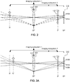
FIGS. 2, 3A and3B depict diagrams illustrating disparity in a plenoptic imaging system, according to an embodiment. -
FIG. 4 shows a block diagram of a processing module, according to an embodiment. -
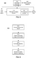
FIG. 5 shows a block diagram of a calibration system for depth-disparity mapping, according to an embodiment. -
FIG. 6 depicts a flow diagram illustrating a method for calibrating a depth-disparity mapping for a plenoptic imaging system, according to an embodiment. -
FIGS. 7A-7C show diagrams illustrating two objects viewed from three different viewpoints.FIG. 7D shows a diagram illustrating an (x,u) slice of the corresponding light field. -
FIG. 8 shows ray regions superimposed on an (x,u) slice from a light field for a grayscale scene. -
FIG. 9 illustrates a plot of disparity angle as a function of depth, according to an embodiment. -
FIG. 10 depicts a diagram of a calibration system, according to an embodiment. -
FIGS. 11A-11B depict diagrams of additional calibration systems, according to an embodiment. -
FIGS. 12A-12D illustrate experiments to calculate a depth-disparity mapping as a function of field position, according to various embodiments. -
FIG. 13 illustrates an experiment to evaluate the calibrations developed inFIG. 12 . - The figures depict various embodiments for purposes of illustration only. One skilled in the art will readily recognize from the following discussion that alternative embodiments of the structures and methods illustrated herein may be employed without departing from the principles described herein.
- The figures and the following description relate to preferred embodiments by way of illustration only. It should be noted that from the following discussion, alternative embodiments of the structures and methods disclosed herein will be readily recognized as viable alternatives that may be employed without departing from the principles of what is claimed.
-
FIGS. 1A-1B depict diagrams illustrating an example of aplenoptic imaging system 110. Theplenoptic imaging system 110 includes primary imaging optics 112 (represented by a single lens inFIG. 1A ), a secondary imaging array 114 (e.g., an array of microlenses 115) and asensor array 180. Thesecondary imaging array 114 may be referred to as a microimaging array. Thesecondary imaging array 114 andsensor array 180 together may be referred to as a plenoptic sensor module. These components form two overlapping imaging subsystems, shown assubsystem 1 andsubsystem 2 inFIG. 1A . - For convenience, the
imaging optics 112 is depicted inFIG. 1A as a single objective lens, but it should be understood that it could contain multiple elements. InFIG. 1A , theobjective lens 112 forms anoptical image 155 of theobject 150 at an image plane IP. When operated at the "in focus" condition, themicroimaging array 114 is located at the image plane IP. The system in its entirety forms spatially multiplexed and interleavedoptical images 170 at the sensor plane SP. Examples ofmicroimaging arrays 114 include microlens arrays, arrays of pinholes, micromirror arrays, checkerboard grids and waveguide/channel arrays. Themicroimaging array 114 can be a rectangular array, hexagonal array or other types of arrays. Thesensor array 180 is also shown inFIG. 1A . - For purposes of illustration, assume that the
microimaging array 114 inFIG. 1A is a 3x3 array of microlenses on a square grid. Theobject 150 is divided into a 3x3 array of regions, which are labeled 1-9 as shown in the lower portion ofFIG. 1A . These regions correspond to the microlenses. That is,object region 1 is imaged byobjective lens 112 onto one of the microlenses, objectregion 2 is imaged onto another microlens, etc. Thesensor array 180 is shown as a 6x6 rectangular array of sensors. That is, there is a 2x2 arrangement of sensors under each microlens. Theaperture 125 is divided into a 2x2 rectangular array of regions A-D. These regions correspond to the 2x2 sensor arrangements. That is, aperture region A is imaged by each microlens onto the corresponding sensor of the 2x2 sensors for that microlens, as are aperture regions B,C,D. In some systems, the aperture regions A-D may be filtered by a different spectral filter, for example. - Note that rays from
object 150 can be defined using four dimensions (x,y,u,v), where (x,y) is a measure of the spatial coordinate from which the ray originates and (u,v) is a measure of the location of the viewpoint to which the ray connects. The division ofobject 150 into 3x3 regions is a partition of the (x,y) space. The division of theaperture 125 into 2x2 regions is a partition of the (u,v) space. For reasons that will be apparent, (x,y) will sometimes be referred to as the field position and (u,v) as the viewpoint. Thus rays that originate fromregion 1 of the object provide information aboutfield position 1 of theobject 150. Rays that propagate through region A of theaperture 125 provide information of theobject 150 from viewpoint A. The data produced by thedetector array 180 is then a sampling of the four-dimensional light field I(x,y,u,v) produced by the object. - A
processing module 190 collects the data from thedetector array 180 and processes it accordingly. As a simple example, theprocessing module 190 may reorder the data, collecting together the data in order to form an image of theentire object 150 for light passing through theaperture 125. Other types of processing can also be performed, since the captured light field data includes information with respect to both the pupil plane and theobject 150. For example, the captured data includes multiple images of the object captured from different viewpoints. The parallax in this data can be used to estimate depth to the object. -
FIG. 1B illustrates conceptually how the spatially multiplexedoptical images 170A-D are produced and interleaved atsensor array 180. Theobject 150 produces rays. The rays that propagate through aperture region A (i.e., viewpoint A) would produce anoptical image 155A at the IP. To identify theoptical image 155A, the 3x3 object regions are labeled with the suffix A: 1A-9A. Similarly, the rays from theobject 150 that propagate through aperture regions B,C,D (viewpoints B,C,D), would produce correspondingoptical images 155B,C,D with 3x3 object regions labeled 1B-9B, 1C-9C and 1D-9D. Each of these fouroptical images 155A-D is produced by rays travelling through different aperture regions A-D but they are all produced simultaneously by theplenoptic imaging system 110 and they are overlapping at the IP. - The four
optical images 155A-D, which are overlapping at the IP, are separated by themicroimaging array 114. Theimages 155A-D are interleaved at the sensor plane, as shown inFIG. 1B . Usingimage 155A as an example, the3x3 object regions 1A-9A fromoptical image 155A are not contiguous in a 3x3 block withinoptical image 170, which for convenience will be referred to as the plenoptic image. Rather,regions image 170 is neglected for clarity). Object regions 2-9 are similarly arranged. Thus, theregions 1A-9A (aka, field positions) that make upoptical image 170A are spread out across theplenoptic image 170, separated by portions of the other optical images 170B-D. Put in another way, if the sensor is a rectangular array of individual sensor elements, the overall array can be divided into rectangular subarrays 171(1)-(9) of sensor elements (the dashed outline shows one subarray 171(1)). For each object region 1-9, all of the corresponding regions from each image are imaged onto the subarray. For example,object regions aperture 125 andsensor array 180 are located in conjugate planes, eachmicrolens 115 inarray 114 forms an image of the pupil plane (same plane as SP') at the sensor plane SP. Since there aremultiple microlenses 115,multiple images 171 are formed. - Further note that, in the system shown in
FIGS. 1A-1B , theoptical images 155A-D are registered with each other. That is,optical image 155A captures the same object region asoptical images 155B,C,D. This is because the object is "in focus," meaning that the image plane for the object is coincident with the location of themicroimaging array 114. Now consider what happens when the object is "out of focus," as illustrated inFIGS. 2-3 . - In
FIG. 2 , consider an object that is located at depth O, which is the "in focus" condition. Now consider a region of the object that is imaged to the center microlens. The solid rays inFIG. 2 show rays from this center region of the object, which also pass through the center of theprimary imaging optics 112. This group of rays is imaged by theprimary imaging optics 112 onto the center microlens, and then imaged by the center microlens ontosensor element 181A. This group of rays represents the light field from the center region of the in focus object as viewed from center viewpoint A. - The dashed rays in
FIG. 2 shows rays from the center region of the object, but which pass through the edge of theprimary imaging optics 112. Because the object is in focus, this dashed group of rays is imaged by theprimary imaging optics 112 onto the center microlens, and then imaged by the center microlens ontosensor element 181B. This group of rays represents the light field from the center region of the in focus object as viewed from an off-axis viewpoint B. - Note that all of the solid rays are collected by
sensor element 181A and all of the dashed rays are collected bysensor element 181B.Sensor element 181A represents the center pixel of the image taken from viewpoint A, andsensor element 181B represents the center pixel of the image taken from viewpoint B. Thus, when the object is in focus, it appears at the same pixel in both the image corresponding to on-axis viewpoint A and the image corresponding to off-axis viewpoint B. - However, this is not the case when the object is out of focus.
FIG. 3A shows an object that is located at depth O', which is "out of focus." The in focus plane O is also shown inFIG. 3 for reference. Similar toFIG. 2, FIG. 3A shows rays traced from the center region of this out of focus object. The solid rays (viewpoint A) are not significantly changed. This group of rays is imaged by theprimary imaging optics 112 onto the center microlens, and then imaged by the center microlens ontosensor element 181A. The out of focus object still appears in the center pixel of the image taken from center viewpoint A. - However, the dashed rays in
FIG. 3A behave significantly differently. As inFIG. 2 , the dashed rays are rays from the center region of the object, and which pass through the edge of theprimary imaging optics 112. These dashed rays can be split into two groups. One group of rays is imaged by theprimary imaging optics 112 onto the center microlens, and then imaged by the center microlens ontosensor element 181B. However, because the object is out of focus, some of the dashed rays are imaged by theprimary imaging optics 112 not onto the center microlens but onto the adjacent microlens. This microlens images these rays ontosensor element 182B, which is the sensor point corresponding to viewpoint B but for the pixel adjacent to the center pixel. Thus, the dashed rays from the center region of the out of focus object will be partially collected bysensor element 181B and partially collected bysensor element 182B.Sensor elements pixels center pixel 181A. This relative shift is referred to as disparity. - In
FIG. 3A , this disparity is sub-pixel, but the disparity can also be more than a pixel or even multiple pixels. For example,FIG. 3B illustrates a situation in which the disparity is a full pixel for an object located at depth O". In this case, the solid rays are still imaged onto thecenter sensor element 181A. However, all of the dashed rays are imaged ontosensor element 182B. Therefore, in the image for viewpoint A, the center object region is located at the center pixel corresponding tosensor element 181A. However, in the image for viewpoint B, the center object region is located not at the center pixel corresponding tosensor element 181B but at the adjacent pixel corresponding tosensor element 182B. So there is a one pixel shift between viewpoints A and B. - As illustrated in
FIGS. 2-3 , the relative shift depends on the depth location of the object. Thus, there is a mapping between depth and disparity. Objects at a certain depth will produce a certain disparity between the multiple images captured in the plenoptic image. Conversely, if the multiple images in the plenoptic image exhibit a certain disparity, this means the object is located at the corresponding depth. Furthermore, if the object is three-dimensional, then the object depth will vary as a function of field position. Some points on the object will be closer to the plenoptic imaging system and some farther away. In addition, due to aberrations or other characteristics of the plenoptic imaging system, the depth-disparity mapping may also vary as a function of field position. A disparity at the center of the field of view may map to a certain depth, but the same disparity at the edge of the field of view may map to a different depth. -
FIG. 4 shows a block diagram of one implementation ofprocessing module 190 that estimates depth. In this example, the multiplexed and interleavedimages 155 are received by aview extraction module 492, which separates the sensor data into separate images 155 (or views). As described above, images of the same point in the object space are shifted relative to each other in these views. That is, they exhibit disparity that depends of the depth of that point. The disparity from one view to the next can be less than one pixel (sub-pixel disparity) or more than one pixel.Disparity determination module 494 calculates the disparity for a set of positions in the field, referred to as a disparity map. For example, it may do this by comparingdifferent views 155. Alternately,disparity determination module 494 may obtain the disparity from other sources, for example user input.Depth estimation module 496 then estimates the depth across the object by mapping the disparity fromdisparity determination module 494 to corresponding depth. It uses a depth-disparity mapping 497 to do this. Themapping 497 between depth and disparity is the result of a calibration process, described in further detail below. The output is adepth map 498 that estimates the depth to different points on the object. In one embodiment, the output image is made of pixels, with conventional image data (e.g., RGB data) for each pixel but also including depth information for each pixel. -
FIG. 5 shows a block diagram of acalibration system 500 for depth-disparity mapping, according to an embodiment.FIG. 6 depicts a flow diagram illustrating amethod 600 for calibrating a depth-disparity mapping for a plenoptic imaging system. InFIG. 5 ,box 110 represents the plenoptic imaging system to be calibrated. Only theprocessing module 190 is explicitly shown. InFIG. 5 , themethod 600 is implemented by thecalibration controller 510. - The
controller 510 controls the presentation of test objects 520. It presents 620 one or more test objects to the plenoptic imaging system. Consider one test object at a time. Thetest object 520 is at a known depth and known field position. Theplenoptic imaging system 110 captures 610 a plenoptic image of the test object. As described above, the image captured by the plenoptic imaging system is processed to create multiple images of the object taken from different viewpoints. Theprocessing module 190 calculates 630 adisparity map 530 for the test object based on the different viewpoint images. In the example ofFIG. 5 , this is done by theprocessing module 190 within the plenoptic imaging system. For example, it may be the output ofdisparity determination module 494 inFIG. 4 . However, this calculation can also be done outside the plenoptic imaging system. The plenoptic image data may be output by the imaging system and then processed to obtain thedisparity map 530. Thecontroller 510 knows the depths and field positions for thetest object 520 and obtains the correspondingdisparities 530. Based on this data, it then determines 640 amapping 540 between depth and disparity as a function of field position. - The depth-disparity mapping may be represented in different forms. It may be stored as a lookup table, possibly using interpolation to estimate values that are not expressly stored in the lookup table. Alternately, the mapping may be represented as a functional mapping, such as a polynomial fit where the coefficients of the polynomial are stored. The processing module of
FIG. 4 can then use the depth-disparity mapping to estimate depth for real objects captured by theplenoptic imaging system 110. -
FIGS. 7-13 illustrate one approach for developing the depth-disparity mapping through calibration. As shown inFIGS. 7A-7D , two-dimensional slices I(x,u) of the four-dimensional light field exhibit a line structure that is inherent to the characteristics of light fields with uniformly spaced viewpoints, where the angle of the line in the (x,u) domain corresponds to different depths in the object.FIG. 7A shows twoobjects Object 720 is forward ofobject 710. It may or may not occludeobject 710, depending on the viewpoint u. -
FIG. 7A is taken from viewpoint u1. From this viewpoint,object 710 occupies thex interval 711 andobject 720 occupies thex interval 721. The twointervals FIG. 7D shows a two-dimensional (x,u) slice of the light field for these two objects. The x-slice ofFIG. 7A is marked by u1 on the vertical u axis. The twointervals FIG. 7D . -
FIG. 7B shows the same two objects from a different viewpoint u2. From this viewpoint,object 710 occupies thex interval 712 andobject 720 occupies thex interval 722. This is also shown by the two line segments at coordinate u=u2 inFIG. 7D . Note that there is a shift of these segments with respect to the segments at coordinate u=u1. This relative shift is due to parallax caused by the change in viewpoint. InFIG. 7B , the two xintervals -
FIG. 7C shows the two objects from viewpoint u3. Here,object 710 occupies thex interval 713 andobject 720 occupies thex interval 723, as also shown by the two line segments at u=u3 inFIG. 7D . The two xintervals object 720 occludes part ofobject 710. The occluded region is the area of overlap. Repeating this process for other viewpoints u results in the twotrapezoids FIG. 7D , which will be referred to as ray regions. The area ofoverlap 739 represents the occlusion ofobject 710 byobject 720. Sinceobject 720 is forward ofobject 710,ray region 729 will be unaffected by theoverlap region 739. That is, the edges ofray region 729 will continue to be parallel. In contrast,ray region 719 will be minus thetriangular overlap region 739. -
FIG. 7D shows an inherent line structure. Each point in an object creates a line in the (x,u) plane at an angle ϕ with respect to the normal to the x axis. A set of adjacent points at the same depth creates a ray region of a certain width, which forms an angle ϕ with the vertical axis. These angles are labeled ϕ1 and ϕ2 inFIG. 7D . In the general four-dimensional case, these angles would be with respect to the normal to the (x,y) plane. For convenience, the angle ϕ will be referred to as the disparity angle. The disparity angle ϕ depends on the depth location of the object. Due to parallax, objects that are farther in depth from the viewpoint u-plane produce lines with a smaller disparity angle ϕ.Ray region 719, which corresponds to object 713 which is farther from the u axis has a lower disparity angle ϕ.Ray region 729, which corresponds to object 723 which is closer to the u axis, has a larger disparity angle ϕ. In some configurations of camera arrays or plenoptic cameras, the angle ϕ can also be negative. These ray regions correspond to objects that are located further behind the focal plane of the main lens, i.e., behind objects that produce vertical ray regions (i.e., ray regions with ϕ = 0). Generally, the angle ϕ can take values within the interval (-π/2, π/2). -
FIG. 8 shows an (x,u) slice from a light field for a grayscale scene.FIG. 8 also shows threeray regions 
- The disparity angle ϕ can be estimated based on the method described in
US Appl. No. 14/064,090 , where σ is a scale dimension and ϕ is a depth or disparity dimension. For convenience, may be referred to a scale-depth transform of I(x,u). The following explanation is presented in two dimensions (x,u) rather than four (x,y,u,v) for clarity of explanation. The scale-depth transformis defined as
 does not depend on u since the convolution is only over x, and thathas both scale σ and angle ϕ as parameters. The kernel for the transformation is referred to as a Ray-Gaussian kernel and is given by
- Similarly, we define the n-th derivative of the Ray-Gaussian transform as:

- We can then find ray regions by finding extrema (local minima and maxima) of the normalized second derivative Ray Gaussian transform

- position of the center of the ray region xp
- width of the ray region 2σp
- angle of the ray region ϕp
- Other methods in the literature can also be used to estimate the disparity angle ϕ. The disparity angle ϕ can be estimated from (y,v) slices or slices at other angles, in addition to the (x,u) slice. The estimated value of ϕ can be used to calculate the disparity Δ. Alternately, processing can proceed based on the disparity angle ϕ instead. Another approach is to use conventional methods to directly estimate the disparity Δ from two or more views, without computing the disparity angle ϕ.
- There is also a one-to-one mapping between disparity angle ϕ (or disparity Δ) and depth value z. This mapping depends on the plenoptic imaging system configuration and typically also varies as a function of field position (i.e., as a function of (x,y) coordinates). The depth-disparity mapping can be obtained by a calibration process. In one approach, the mapping is fitted into a linear model:

-
FIG. 9 illustrates a plot of disparity angle as a function of depth for an example plenoptic imaging system. The linear fit of Eqn. 4 is a good approximation typically for a given depth range around focus. In a more general scenario, coefficients a and b may vary as a function of depth z. In one approach, the coefficient a is approximately constant throughout the field, while the coefficient b varies from the center to the edge due to the field curvature. The amount of variation depends on the optics in use. For example, inFig. 12D , the coefficient b varies from -0.2mm at the center to -0.6 mm at the edge. -
FIG. 10 depicts a diagram of a calibration system, according to an embodiment. Theplenoptic imaging system 110 is represented by a lens, a microlens array (MLA) and a focal plane array (FPA). The test object is apoint object 1050, which in this example is implemented as a pinhole used to spatially filter a light source. The illuminated pinhole is imaged by theplenoptic imaging system 110. To construct the lookup tables between disparity and depth, thepinhole 1050 is scanned along three axes - laterally to different field positions across the imaging field of view (FOV) and axially to different depths across the depth of focus. Scanning thepoint object 1050 effectively samples the depth-disparity mapping over a range of depths and field positions. In one approach, the samples are uniformly spaced in depth and in field position, and thepoint object 1050 is scanned over the entire field of view and over the entire depth of field (e.g., as defined by a pinhole aperture). Thepoint object 1050 can be scanned using different scanning patterns, and it could be scanned over other ranges of depth and field position. In another approach, the optical system is assumed to be axially symmetric and thepinhole 1050 is scanned along only two axes: one lateral and one axial. Scanning patterns can also take advantage of other types of symmetry. - The captured plenoptic images are processed as described above to determine the disparity corresponding to each position of the
test object 1050. In this way, each scan point produces a pairing of depth and disparity for a given field position. This data is fit to the linear model given by Eqn. 4, producing estimates for the coefficients a and b as a function of field position. -
FIGS. 11A-11B depict diagrams of additional calibration systems, according to an embodiment. These examples use a planar test object 1150 that is moved to different depth locations. InFIG. 11A , theplanar object 1150A is a physical grid mask used to filter a light source. The illumination light is first collimated by a lens and then shined onto a diffuser. The gridded object is illuminated by the diffused light and imaged by theplenoptic imaging system 110. Rather than scanning along all three axes as in the pinhole-scanning-based approach, the grid mask here scans along only the z axis, thereby speeding up the calibration by a factor of Nx × Ny (Nx, Ny, the number of scanning positions along the x,y axes). - In
FIG. 11B , anelectronic display screen 1150B, such as a liquid-crystal display (LCD), is used as the test object. A grid pattern, such as a grid of point objects, is displayed on the screen and imaged by theplenoptic imaging system 110. To sample the disparity-to-depth mapping, scanning is performed along only the z axis. Compared with the implementation that uses a physical grid mask, the display-based approach does not require external illumination, thereby resulting in a simplified experimental setup. - As an experiment, we calibrated a light field camera with an input numerical aperture of 0.03 (object side) using both the pinhole-scanning-based and grid-scanning-based approaches, respectively. In the pinhole-scanning-based calibration, we scanned a pinhole-filtered light source across 100×30 points on the x-z plane with a step size of 0.1 mm. In the grid-scanning-based calibration, we scanned a grid target (period, 0.4 mm) along the z axis with 0.1 mm step size and acquired a total of 30 images.
-
FIG. 12A shows the calculated depth-disparity mapping as a function of field position x using the pinhole-scanning-based calibration, andFIG. 12B shows the calculated depth-disparity mapping using the grid-scanning-based calibration. Notably, the curved contour of disparity angles is due to the field curvature aberration. -
FIGS. 12C and 12D show the coefficients and obtained by fitting the data fromFIGS. 12A and 12B , to the linear model of Eqn. 4. The results show that the coefficients a(x) and b(x) calculated by both methods are closely matched across the 3 mm range of depth z and across the 8 mm range of field position x. In this example, we have scanned along the x-axis only and assumed circular symmetry to obtain the full x-y plane, but in general the y-axis can also be scanned. - The coefficients obtained above were then used for depth estimation as a test of the calibration procedure. We imaged a planar real object (a grid pattern with a period of 0.8 mm) at a nominal depth of 27 mm. A disparity map was calculated from the acquired plenoptic image. The disparity angle at each field position was converted to depth using the linear coefficients a and b obtained by the pinhole-scanning-based calibration and by the grid-scanning-based calibration. The reconstructed depths across a line image are shown in
FIG. 13 . The mean values of reconstructed depths calculated by both methods closely match with the ground truth. The depth accuracy, defined as the standard deviation of reconstructed depths, is ∼ 0.3 mm for both methods. x=50 corresponds to the center of the image. - Although the detailed description contains many specifics, these should not be construed as limiting the scope of the invention but merely as illustrating different examples and aspects of the invention. It should be appreciated that the scope of the invention includes other embodiments not discussed in detail above. For example, other combinations will be apparent. In one alternative, pinhole scanning is used to acquire samples of the depth-disparity mapping over a range of depths and field positions, and this acquired data is fit to a linear model of the depth-disparity mapping. In an alternate approach, scanning with a planar test object is used to acquire samples of the depth-disparity mapping, and the mapping is then represented by a lookup table of values. Various other modifications, changes and variations which will be apparent to those skilled in the art may be made in the arrangement, operation and details of the method and apparatus of the present invention disclosed herein without departing from the scope of the invention as defined in the appended claims. Therefore, the scope of the invention should be determined by the appended claims and their legal equivalents.
- In the claims, reference to an element in the singular is not intended to mean "one and only one" unless explicitly stated, but rather is meant to mean "one or more." In addition, it is not necessary for a device or method to address every problem that is solvable by different embodiments of the invention in order to be encompassed by the claims.
- In alternate embodiments, aspects of the invention are implemented in computer hardware, firmware, software, and/or combinations thereof. Apparatus of the invention can be implemented in a computer program product tangibly embodied in a machine-readable storage device for execution by a programmable processor; and method steps of the invention can be performed by a programmable processor executing a program of instructions to perform functions of the invention by operating on input data and generating output. The invention can be implemented advantageously in one or more computer programs that are executable on a programmable system including at least one programmable processor coupled to receive data and instructions from, and to transmit data and instructions to, a data storage system, at least one input device, and at least one output device. Each computer program can be implemented in a high-level procedural or object-oriented programming language, or in assembly or machine language if desired; and in any case, the language can be a compiled or interpreted language. Suitable processors include, by way of example, both general and special purpose microprocessors. Generally, a processor will receive instructions and data from a read-only memory and/or a random access memory. Generally, a computer will include one or more mass storage devices for storing data files; such devices include magnetic disks, such as internal hard disks and removable disks; magneto-optical disks; and optical disks. Storage devices suitable for tangibly embodying computer program instructions and data include all forms of non-volatile memory, including by way of example semiconductor memory devices, such as EPROM, EEPROM, and flash memory devices; magnetic disks such as internal hard disks and removable disks; magneto-optical disks; and CD-ROM disks. Any of the foregoing can be supplemented by, or incorporated in, ASICs (application-specific integrated circuits) and other forms of hardware.
- The term "module" is not meant to be limited to a specific physical form. Depending on the specific application, modules can be implemented as hardware, firmware, software, and/or combinations of these. In the receiver described above, the modules were implemented as dedicated circuitry (e.g., part of an ASIC), in order to take advantage of lower power consumption and higher speed. In other applications, the modules can be implemented as software, typically running on digital signal processors or even general-purpose processors. Various combinations can also be used. Furthermore, different modules can share common components or even be implemented by the same components. There may or may not be a clear boundary between different modules.
- The present application is based on and claims the benefit of priority of
U.S. Patent Application No. 15/050,422, filed on February 22, 2016 .
Claims (13)
- A method for calibrating a depth-disparity mapping for a plenoptic imaging system, the method comprising:presenting one or more test objects to the plenoptic imaging system, the test objects located at known field positions and known depths;the plenoptic imaging system capturing plenoptic images of the test objects, the plenoptic images comprising multiple images of the test objects captured from different viewpoints;calculating disparity angles for the test objects based on the multiple images taken from different viewpoints; wherein in a field position - viewpoint plane (x,u), with one axis (x) being the field position axis, and the other axis (u) being the viewpoint axis, each point of the test objects in the plenoptic images creates a line in the field position - viewpoint plane (x,u), and the angle of the line with respect to the normal to the field position axis is defined to be the disparity angle, anddetermining coefficients for a linear mapping between depth and disparity angle as a function of field position, based on the calculated disparity angles and the corresponding known depths for the test objects for different known field positions of the test objects.
- The method of claim 1 wherein:presenting test objects to the plenoptic imaging system comprises moving a point object to different depths and field positions spanning a range of depths and a range of field positions; andcapturing plenoptic images of the test objects comprises capturing plenoptic images of the point object over the range of depths and over the range of field positions.
- The method of claim 1 wherein:presenting test objects to the plenoptic imaging system comprises moving a planar object to different depths spanning a range of depths; andcapturing plenoptic images of the test objects comprises capturing plenoptic images of the planar object over the range of depths.
- The method of claim 3 wherein the planar object is a gridded object.
- The method of claim 3 wherein the planar object is a grid of point objects.
- The method of claim 1 wherein presenting test objects to the plenoptic imaging system provides samples of the mapping between depth and disparity over a range of depths and over a range of field positions.
- The method of claim 6 wherein the samples are uniformly spaced over the range of depths.
- The method of claim 6 wherein the samples are uniformly spaced over the range of field positions.
- The method of claim 1 wherein calculating disparities for the test objects comprises calculating disparities for the test objects based on multiple images of the test objects taken from viewpoints that vary along one dimension.
- The method of claim 1 wherein the mapping between depth and disparity angle varies as a function of field position.
- The method of claim 1 wherein the variation in the mapping between depth and disparity as a function of field position is caused by aberrations in the plenoptic imaging system.
- The method of claim 1 further comprising:
storing the mapping between depth and disparity as a lookup table. - A computer program product for calibrating a depth-disparity mapping for a plenoptic imaging system, the computer program product stored on a non-transitory computer readable medium and including program code for performing a method comprising:causing a calibration system to present one or more test objects to the plenoptic imaging system, the test objects located at known field positions and known depths;causing the plenoptic imaging system to capture plenoptic images of the test objects, the plenoptic images comprising multiple images of the test objects captured from different viewpoints;calculating disparity angles for the test objects based on the multiple images taken from different viewpoints; wherein in a field position - viewpoint plane (x,u), with one axis (x) being the field position axis, and the other axis (u) being the viewpoint axis, each point of the test objects in the plenoptic images creates a line in the field position - viewpoint plane (x,u), and the angle of the line with respect to the normal to the field position axis is defined to be the disparity angle, anddetermining coefficients for a linear mapping between depth and disparity angle as a function of field position, based on the calculated disparity angles and the corresponding known depths for the test objects for different known field positions of the test objects.
Applications Claiming Priority (1)
| Application Number | Priority Date | Filing Date | Title |
|---|---|---|---|
| US15/050,422 US10194139B2 (en) | 2016-02-22 | 2016-02-22 | Disparity-to-depth calibration for plenoptic imaging systems |
Publications (2)
| Publication Number | Publication Date |
|---|---|
| EP3208773A1 EP3208773A1 (en) | 2017-08-23 |
| EP3208773B1 true EP3208773B1 (en) | 2018-06-13 |
Family
ID=57963079
Family Applications (1)
| Application Number | Title | Priority Date | Filing Date |
|---|---|---|---|
| EP17154455.4A Not-in-force EP3208773B1 (en) | 2016-02-22 | 2017-02-02 | Disparity-to-depth calibration for plenoptic imaging systems |
Country Status (3)
| Country | Link |
|---|---|
| US (1) | US10194139B2 (en) |
| EP (1) | EP3208773B1 (en) |
| JP (1) | JP6292327B2 (en) |
Families Citing this family (5)
| Publication number | Priority date | Publication date | Assignee | Title |
|---|---|---|---|---|
| CA3214444A1 (en) | 2016-04-12 | 2017-10-19 | Quidient, Llc | Quotidian scene reconstruction engine |
| WO2019157571A1 (en) * | 2018-02-19 | 2019-08-22 | Integral Scopes Pty Ltd | Method and system for calibrating a plenoptic camera system |
| US11875476B2 (en) | 2018-05-02 | 2024-01-16 | Quidient, Llc | Codec for processing scenes of almost unlimited detail |
| US11030776B2 (en) | 2019-02-01 | 2021-06-08 | Molecular Devices (Austria) GmbH | Calibration of a light-field imaging system |
| CN113205592B (en) * | 2021-05-14 | 2022-08-05 | 湖北工业大学 | Light field three-dimensional reconstruction method and system based on phase similarity |
Family Cites Families (8)
| Publication number | Priority date | Publication date | Assignee | Title |
|---|---|---|---|---|
| US8139045B2 (en) * | 2006-12-15 | 2012-03-20 | Lg Display Co., Ltd. | Display device having multi-touch recognizing function and driving method thereof |
| US8803918B2 (en) | 2010-08-27 | 2014-08-12 | Adobe Systems Incorporated | Methods and apparatus for calibrating focused plenoptic camera data |
| JP6044868B2 (en) * | 2012-06-26 | 2016-12-14 | 株式会社リコー | Stereo camera calibration apparatus and method, and distance measurement apparatus |
| WO2014031795A1 (en) * | 2012-08-21 | 2014-02-27 | Pelican Imaging Corporation | Systems and methods for parallax detection and correction in images captured using array cameras |
| US9781416B2 (en) * | 2013-02-26 | 2017-10-03 | Qualcomm Incorporated | Neighboring block disparity vector derivation in 3D video coding |
| US9460515B2 (en) | 2013-10-25 | 2016-10-04 | Ricoh Co., Ltd. | Processing of light fields by transforming to scale and depth space |
| US9888229B2 (en) * | 2014-06-23 | 2018-02-06 | Ricoh Company, Ltd. | Disparity estimation for multiview imaging systems |
| US9955861B2 (en) | 2015-10-16 | 2018-05-01 | Ricoh Company, Ltd. | Construction of an individual eye model using a plenoptic camera |
-
2016
- 2016-02-22 US US15/050,422 patent/US10194139B2/en active Active
-
2017
- 2017-02-02 EP EP17154455.4A patent/EP3208773B1/en not_active Not-in-force
- 2017-02-07 JP JP2017020056A patent/JP6292327B2/en not_active Expired - Fee Related
Non-Patent Citations (1)
| Title |
|---|
| None * |
Also Published As
| Publication number | Publication date |
|---|---|
| EP3208773A1 (en) | 2017-08-23 |
| US10194139B2 (en) | 2019-01-29 |
| JP6292327B2 (en) | 2018-03-14 |
| US20170244957A1 (en) | 2017-08-24 |
| JP2017153071A (en) | 2017-08-31 |
Similar Documents
| Publication | Publication Date | Title |
|---|---|---|
| EP3208773B1 (en) | Disparity-to-depth calibration for plenoptic imaging systems | |
| US8305485B2 (en) | Digital camera with coded aperture rangefinder | |
| EP3043317A1 (en) | Object space calibration of plenoptic imaging systems | |
| CN107113370B (en) | Image recording apparatus and method of recording image | |
| US8582820B2 (en) | Coded aperture camera with adaptive image processing | |
| EP2866202A2 (en) | Processing of light fields by transforming to scale and depth space | |
| CN103003665B (en) | Stereo distance measurement apparatus | |
| US8723926B2 (en) | Parallax detecting apparatus, distance measuring apparatus, and parallax detecting method | |
| US20160165206A1 (en) | Digital refocusing method | |
| JP6786225B2 (en) | Image processing equipment, imaging equipment and image processing programs | |
| JP5810314B2 (en) | Stereo image processing apparatus and stereo image processing method | |
| CN111402127B (en) | Method and device for removing optical aberration based on light field information | |
| US9438887B2 (en) | Depth measurement apparatus and controlling method thereof | |
| JP2009288042A (en) | Distance measuring device | |
| CN107209061B (en) | Method for determining complex amplitude of scene-dependent electromagnetic field | |
| EP3065402B1 (en) | Disparity in plenoptic systems | |
| WO2019048904A1 (en) | Combined stereoscopic and phase detection depth mapping in a dual aperture camera | |
| JP2016225811A (en) | Image processing apparatus, image processing method, and program | |
| JP6968895B2 (en) | Method and optical system to acquire tomographic distribution of electromagnetic field crest | |
| US9525819B2 (en) | Enhancing spatial resolution of images from light field imaging systems using sub-pixel disparity | |
| KR101857977B1 (en) | Image apparatus for combining plenoptic camera and depth camera, and image processing method | |
| AU2022204926B2 (en) | System and Method for Extracting Information on the Spatial Distribution of Wavefronts | |
| CN109556574B (en) | Pose detection system based on fovea system |
Legal Events
| Date | Code | Title | Description |
|---|---|---|---|
| PUAI | Public reference made under article 153(3) epc to a published international application that has entered the european phase |
Free format text: ORIGINAL CODE: 0009012 |
|
| STAA | Information on the status of an ep patent application or granted ep patent |
Free format text: STATUS: REQUEST FOR EXAMINATION WAS MADE |
|
| 17P | Request for examination filed |
Effective date: 20170202 |
|
| AK | Designated contracting states |
Kind code of ref document: A1 Designated state(s): AL AT BE BG CH CY CZ DE DK EE ES FI FR GB GR HR HU IE IS IT LI LT LU LV MC MK MT NL NO PL PT RO RS SE SI SK SM TR |
|
| AX | Request for extension of the european patent |
Extension state: BA ME |
|
| GRAP | Despatch of communication of intention to grant a patent |
Free format text: ORIGINAL CODE: EPIDOSNIGR1 |
|
| STAA | Information on the status of an ep patent application or granted ep patent |
Free format text: STATUS: GRANT OF PATENT IS INTENDED |
|
| RIC1 | Information provided on ipc code assigned before grant |
Ipc: G06T 7/557 20170101AFI20171106BHEP Ipc: H04N 13/02 20060101ALI20171106BHEP Ipc: H04N 13/00 20060101ALI20171106BHEP Ipc: G06T 7/80 20170101ALI20171106BHEP |
|
| INTG | Intention to grant announced |
Effective date: 20171127 |
|
| GRAJ | Information related to disapproval of communication of intention to grant by the applicant or resumption of examination proceedings by the epo deleted |
Free format text: ORIGINAL CODE: EPIDOSDIGR1 |
|
| STAA | Information on the status of an ep patent application or granted ep patent |
Free format text: STATUS: REQUEST FOR EXAMINATION WAS MADE |
|
| RIN1 | Information on inventor provided before grant (corrected) |
Inventor name: TOSIC, IVANA Inventor name: GAO, LIANG Inventor name: BEDARD, NOAH |
|
| GRAR | Information related to intention to grant a patent recorded |
Free format text: ORIGINAL CODE: EPIDOSNIGR71 |
|
| GRAS | Grant fee paid |
Free format text: ORIGINAL CODE: EPIDOSNIGR3 |
|
| STAA | Information on the status of an ep patent application or granted ep patent |
Free format text: STATUS: GRANT OF PATENT IS INTENDED |
|
| GRAA | (expected) grant |
Free format text: ORIGINAL CODE: 0009210 |
|
| STAA | Information on the status of an ep patent application or granted ep patent |
Free format text: STATUS: THE PATENT HAS BEEN GRANTED |
|
| INTC | Intention to grant announced (deleted) | ||
| RIC1 | Information provided on ipc code assigned before grant |
Ipc: G06T 7/557 20170101AFI20180417BHEP Ipc: G06T 7/80 20170101ALI20180417BHEP Ipc: H04N 13/00 20060101ALI20180417BHEP |
|
| INTG | Intention to grant announced |
Effective date: 20180426 |
|
| AK | Designated contracting states |
Kind code of ref document: B1 Designated state(s): AL AT BE BG CH CY CZ DE DK EE ES FI FR GB GR HR HU IE IS IT LI LT LU LV MC MK MT NL NO PL PT RO RS SE SI SK SM TR |
|
| REG | Reference to a national code |
Ref country code: GB Ref legal event code: FG4D |
|
| REG | Reference to a national code |
Ref country code: CH Ref legal event code: EP Ref country code: AT Ref legal event code: REF Ref document number: 1009241 Country of ref document: AT Kind code of ref document: T Effective date: 20180615 |
|
| REG | Reference to a national code |
Ref country code: IE Ref legal event code: FG4D |
|
| REG | Reference to a national code |
Ref country code: DE Ref legal event code: R096 Ref document number: 602017000095 Country of ref document: DE |
|
| REG | Reference to a national code |
Ref country code: NL Ref legal event code: MP Effective date: 20180613 |
|
| REG | Reference to a national code |
Ref country code: LT Ref legal event code: MG4D |
|
| PG25 | Lapsed in a contracting state [announced via postgrant information from national office to epo] |
Ref country code: CY Free format text: LAPSE BECAUSE OF FAILURE TO SUBMIT A TRANSLATION OF THE DESCRIPTION OR TO PAY THE FEE WITHIN THE PRESCRIBED TIME-LIMIT Effective date: 20180613 Ref country code: LT Free format text: LAPSE BECAUSE OF FAILURE TO SUBMIT A TRANSLATION OF THE DESCRIPTION OR TO PAY THE FEE WITHIN THE PRESCRIBED TIME-LIMIT Effective date: 20180613 Ref country code: BG Free format text: LAPSE BECAUSE OF FAILURE TO SUBMIT A TRANSLATION OF THE DESCRIPTION OR TO PAY THE FEE WITHIN THE PRESCRIBED TIME-LIMIT Effective date: 20180913 Ref country code: FI Free format text: LAPSE BECAUSE OF FAILURE TO SUBMIT A TRANSLATION OF THE DESCRIPTION OR TO PAY THE FEE WITHIN THE PRESCRIBED TIME-LIMIT Effective date: 20180613 Ref country code: NO Free format text: LAPSE BECAUSE OF FAILURE TO SUBMIT A TRANSLATION OF THE DESCRIPTION OR TO PAY THE FEE WITHIN THE PRESCRIBED TIME-LIMIT Effective date: 20180913 Ref country code: SE Free format text: LAPSE BECAUSE OF FAILURE TO SUBMIT A TRANSLATION OF THE DESCRIPTION OR TO PAY THE FEE WITHIN THE PRESCRIBED TIME-LIMIT Effective date: 20180613 |
|
| PG25 | Lapsed in a contracting state [announced via postgrant information from national office to epo] |
Ref country code: GR Free format text: LAPSE BECAUSE OF FAILURE TO SUBMIT A TRANSLATION OF THE DESCRIPTION OR TO PAY THE FEE WITHIN THE PRESCRIBED TIME-LIMIT Effective date: 20180914 Ref country code: HR Free format text: LAPSE BECAUSE OF FAILURE TO SUBMIT A TRANSLATION OF THE DESCRIPTION OR TO PAY THE FEE WITHIN THE PRESCRIBED TIME-LIMIT Effective date: 20180613 Ref country code: LV Free format text: LAPSE BECAUSE OF FAILURE TO SUBMIT A TRANSLATION OF THE DESCRIPTION OR TO PAY THE FEE WITHIN THE PRESCRIBED TIME-LIMIT Effective date: 20180613 Ref country code: RS Free format text: LAPSE BECAUSE OF FAILURE TO SUBMIT A TRANSLATION OF THE DESCRIPTION OR TO PAY THE FEE WITHIN THE PRESCRIBED TIME-LIMIT Effective date: 20180613 |
|
| REG | Reference to a national code |
Ref country code: AT Ref legal event code: MK05 Ref document number: 1009241 Country of ref document: AT Kind code of ref document: T Effective date: 20180613 |
|
| PG25 | Lapsed in a contracting state [announced via postgrant information from national office to epo] |
Ref country code: NL Free format text: LAPSE BECAUSE OF FAILURE TO SUBMIT A TRANSLATION OF THE DESCRIPTION OR TO PAY THE FEE WITHIN THE PRESCRIBED TIME-LIMIT Effective date: 20180613 |
|
| PG25 | Lapsed in a contracting state [announced via postgrant information from national office to epo] |
Ref country code: RO Free format text: LAPSE BECAUSE OF FAILURE TO SUBMIT A TRANSLATION OF THE DESCRIPTION OR TO PAY THE FEE WITHIN THE PRESCRIBED TIME-LIMIT Effective date: 20180613 Ref country code: SK Free format text: LAPSE BECAUSE OF FAILURE TO SUBMIT A TRANSLATION OF THE DESCRIPTION OR TO PAY THE FEE WITHIN THE PRESCRIBED TIME-LIMIT Effective date: 20180613 Ref country code: CZ Free format text: LAPSE BECAUSE OF FAILURE TO SUBMIT A TRANSLATION OF THE DESCRIPTION OR TO PAY THE FEE WITHIN THE PRESCRIBED TIME-LIMIT Effective date: 20180613 Ref country code: IS Free format text: LAPSE BECAUSE OF FAILURE TO SUBMIT A TRANSLATION OF THE DESCRIPTION OR TO PAY THE FEE WITHIN THE PRESCRIBED TIME-LIMIT Effective date: 20181013 Ref country code: PL Free format text: LAPSE BECAUSE OF FAILURE TO SUBMIT A TRANSLATION OF THE DESCRIPTION OR TO PAY THE FEE WITHIN THE PRESCRIBED TIME-LIMIT Effective date: 20180613 Ref country code: AT Free format text: LAPSE BECAUSE OF FAILURE TO SUBMIT A TRANSLATION OF THE DESCRIPTION OR TO PAY THE FEE WITHIN THE PRESCRIBED TIME-LIMIT Effective date: 20180613 Ref country code: EE Free format text: LAPSE BECAUSE OF FAILURE TO SUBMIT A TRANSLATION OF THE DESCRIPTION OR TO PAY THE FEE WITHIN THE PRESCRIBED TIME-LIMIT Effective date: 20180613 |
|
| PG25 | Lapsed in a contracting state [announced via postgrant information from national office to epo] |
Ref country code: SM Free format text: LAPSE BECAUSE OF FAILURE TO SUBMIT A TRANSLATION OF THE DESCRIPTION OR TO PAY THE FEE WITHIN THE PRESCRIBED TIME-LIMIT Effective date: 20180613 Ref country code: IT Free format text: LAPSE BECAUSE OF FAILURE TO SUBMIT A TRANSLATION OF THE DESCRIPTION OR TO PAY THE FEE WITHIN THE PRESCRIBED TIME-LIMIT Effective date: 20180613 |
|
| REG | Reference to a national code |
Ref country code: DE Ref legal event code: R097 Ref document number: 602017000095 Country of ref document: DE |
|
| PLBE | No opposition filed within time limit |
Free format text: ORIGINAL CODE: 0009261 |
|
| STAA | Information on the status of an ep patent application or granted ep patent |
Free format text: STATUS: NO OPPOSITION FILED WITHIN TIME LIMIT |
|
| 26N | No opposition filed |
Effective date: 20190314 |
|
| PG25 | Lapsed in a contracting state [announced via postgrant information from national office to epo] |
Ref country code: DK Free format text: LAPSE BECAUSE OF FAILURE TO SUBMIT A TRANSLATION OF THE DESCRIPTION OR TO PAY THE FEE WITHIN THE PRESCRIBED TIME-LIMIT Effective date: 20180613 |
|
| PG25 | Lapsed in a contracting state [announced via postgrant information from national office to epo] |
Ref country code: ES Free format text: LAPSE BECAUSE OF FAILURE TO SUBMIT A TRANSLATION OF THE DESCRIPTION OR TO PAY THE FEE WITHIN THE PRESCRIBED TIME-LIMIT Effective date: 20180613 |
|
| PG25 | Lapsed in a contracting state [announced via postgrant information from national office to epo] |
Ref country code: MC Free format text: LAPSE BECAUSE OF FAILURE TO SUBMIT A TRANSLATION OF THE DESCRIPTION OR TO PAY THE FEE WITHIN THE PRESCRIBED TIME-LIMIT Effective date: 20180613 Ref country code: LU Free format text: LAPSE BECAUSE OF NON-PAYMENT OF DUE FEES Effective date: 20190202 |
|
| REG | Reference to a national code |
Ref country code: BE Ref legal event code: MM Effective date: 20190228 |
|
| REG | Reference to a national code |
Ref country code: IE Ref legal event code: MM4A |
|
| PG25 | Lapsed in a contracting state [announced via postgrant information from national office to epo] |
Ref country code: AL Free format text: LAPSE BECAUSE OF FAILURE TO SUBMIT A TRANSLATION OF THE DESCRIPTION OR TO PAY THE FEE WITHIN THE PRESCRIBED TIME-LIMIT Effective date: 20180613 |
|
| PG25 | Lapsed in a contracting state [announced via postgrant information from national office to epo] |
Ref country code: IE Free format text: LAPSE BECAUSE OF NON-PAYMENT OF DUE FEES Effective date: 20190202 |
|
| PG25 | Lapsed in a contracting state [announced via postgrant information from national office to epo] |
Ref country code: BE Free format text: LAPSE BECAUSE OF NON-PAYMENT OF DUE FEES Effective date: 20190228 |
|
| PG25 | Lapsed in a contracting state [announced via postgrant information from national office to epo] |
Ref country code: TR Free format text: LAPSE BECAUSE OF FAILURE TO SUBMIT A TRANSLATION OF THE DESCRIPTION OR TO PAY THE FEE WITHIN THE PRESCRIBED TIME-LIMIT Effective date: 20180613 |
|
| PGFP | Annual fee paid to national office [announced via postgrant information from national office to epo] |
Ref country code: DE Payment date: 20200219 Year of fee payment: 4 |
|
| PG25 | Lapsed in a contracting state [announced via postgrant information from national office to epo] |
Ref country code: PT Free format text: LAPSE BECAUSE OF FAILURE TO SUBMIT A TRANSLATION OF THE DESCRIPTION OR TO PAY THE FEE WITHIN THE PRESCRIBED TIME-LIMIT Effective date: 20181015 Ref country code: MT Free format text: LAPSE BECAUSE OF NON-PAYMENT OF DUE FEES Effective date: 20190202 |
|
| PGFP | Annual fee paid to national office [announced via postgrant information from national office to epo] |
Ref country code: FR Payment date: 20200219 Year of fee payment: 4 |
|
| REG | Reference to a national code |
Ref country code: CH Ref legal event code: PL |
|
| PG25 | Lapsed in a contracting state [announced via postgrant information from national office to epo] |
Ref country code: LI Free format text: LAPSE BECAUSE OF NON-PAYMENT OF DUE FEES Effective date: 20200229 Ref country code: CH Free format text: LAPSE BECAUSE OF NON-PAYMENT OF DUE FEES Effective date: 20200229 |
|
| PG25 | Lapsed in a contracting state [announced via postgrant information from national office to epo] |
Ref country code: HU Free format text: LAPSE BECAUSE OF FAILURE TO SUBMIT A TRANSLATION OF THE DESCRIPTION OR TO PAY THE FEE WITHIN THE PRESCRIBED TIME-LIMIT; INVALID AB INITIO Effective date: 20170202 |
|
| REG | Reference to a national code |
Ref country code: DE Ref legal event code: R119 Ref document number: 602017000095 Country of ref document: DE |
|
| GBPC | Gb: european patent ceased through non-payment of renewal fee |
Effective date: 20210202 |
|
| PG25 | Lapsed in a contracting state [announced via postgrant information from national office to epo] |
Ref country code: SI Free format text: LAPSE BECAUSE OF FAILURE TO SUBMIT A TRANSLATION OF THE DESCRIPTION OR TO PAY THE FEE WITHIN THE PRESCRIBED TIME-LIMIT Effective date: 20180613 |
|
| PG25 | Lapsed in a contracting state [announced via postgrant information from national office to epo] |
Ref country code: DE Free format text: LAPSE BECAUSE OF NON-PAYMENT OF DUE FEES Effective date: 20210901 Ref country code: FR Free format text: LAPSE BECAUSE OF NON-PAYMENT OF DUE FEES Effective date: 20210228 Ref country code: GB Free format text: LAPSE BECAUSE OF NON-PAYMENT OF DUE FEES Effective date: 20210202 |
|
| PG25 | Lapsed in a contracting state [announced via postgrant information from national office to epo] |
Ref country code: MK Free format text: LAPSE BECAUSE OF FAILURE TO SUBMIT A TRANSLATION OF THE DESCRIPTION OR TO PAY THE FEE WITHIN THE PRESCRIBED TIME-LIMIT Effective date: 20180613 |