EP3208648A1 - Head-up display device - Google Patents
Head-up display device Download PDFInfo
- Publication number
- EP3208648A1 EP3208648A1 EP15850928.1A EP15850928A EP3208648A1 EP 3208648 A1 EP3208648 A1 EP 3208648A1 EP 15850928 A EP15850928 A EP 15850928A EP 3208648 A1 EP3208648 A1 EP 3208648A1
- Authority
- EP
- European Patent Office
- Prior art keywords
- light
- projection
- image
- adjustment means
- projection light
- Prior art date
- Legal status (The legal status is an assumption and is not a legal conclusion. Google has not performed a legal analysis and makes no representation as to the accuracy of the status listed.)
- Withdrawn
Links
Images

Classifications
-
- G—PHYSICS
- G02—OPTICS
- G02B—OPTICAL ELEMENTS, SYSTEMS OR APPARATUS
- G02B27/00—Optical systems or apparatus not provided for by any of the groups G02B1/00 - G02B26/00, G02B30/00
- G02B27/01—Head-up displays
- G02B27/0101—Head-up displays characterised by optical features
-
- B—PERFORMING OPERATIONS; TRANSPORTING
- B60—VEHICLES IN GENERAL
- B60K—ARRANGEMENT OR MOUNTING OF PROPULSION UNITS OR OF TRANSMISSIONS IN VEHICLES; ARRANGEMENT OR MOUNTING OF PLURAL DIVERSE PRIME-MOVERS IN VEHICLES; AUXILIARY DRIVES FOR VEHICLES; INSTRUMENTATION OR DASHBOARDS FOR VEHICLES; ARRANGEMENTS IN CONNECTION WITH COOLING, AIR INTAKE, GAS EXHAUST OR FUEL SUPPLY OF PROPULSION UNITS IN VEHICLES
- B60K35/00—Instruments specially adapted for vehicles; Arrangement of instruments in or on vehicles
- B60K35/10—Input arrangements, i.e. from user to vehicle, associated with vehicle functions or specially adapted therefor
-
- B—PERFORMING OPERATIONS; TRANSPORTING
- B60—VEHICLES IN GENERAL
- B60K—ARRANGEMENT OR MOUNTING OF PROPULSION UNITS OR OF TRANSMISSIONS IN VEHICLES; ARRANGEMENT OR MOUNTING OF PLURAL DIVERSE PRIME-MOVERS IN VEHICLES; AUXILIARY DRIVES FOR VEHICLES; INSTRUMENTATION OR DASHBOARDS FOR VEHICLES; ARRANGEMENTS IN CONNECTION WITH COOLING, AIR INTAKE, GAS EXHAUST OR FUEL SUPPLY OF PROPULSION UNITS IN VEHICLES
- B60K35/00—Instruments specially adapted for vehicles; Arrangement of instruments in or on vehicles
- B60K35/20—Output arrangements, i.e. from vehicle to user, associated with vehicle functions or specially adapted therefor
- B60K35/21—Output arrangements, i.e. from vehicle to user, associated with vehicle functions or specially adapted therefor using visual output, e.g. blinking lights or matrix displays
- B60K35/213—Virtual instruments
-
- B—PERFORMING OPERATIONS; TRANSPORTING
- B60—VEHICLES IN GENERAL
- B60K—ARRANGEMENT OR MOUNTING OF PROPULSION UNITS OR OF TRANSMISSIONS IN VEHICLES; ARRANGEMENT OR MOUNTING OF PLURAL DIVERSE PRIME-MOVERS IN VEHICLES; AUXILIARY DRIVES FOR VEHICLES; INSTRUMENTATION OR DASHBOARDS FOR VEHICLES; ARRANGEMENTS IN CONNECTION WITH COOLING, AIR INTAKE, GAS EXHAUST OR FUEL SUPPLY OF PROPULSION UNITS IN VEHICLES
- B60K35/00—Instruments specially adapted for vehicles; Arrangement of instruments in or on vehicles
- B60K35/20—Output arrangements, i.e. from vehicle to user, associated with vehicle functions or specially adapted therefor
- B60K35/21—Output arrangements, i.e. from vehicle to user, associated with vehicle functions or specially adapted therefor using visual output, e.g. blinking lights or matrix displays
- B60K35/23—Head-up displays [HUD]
-
- B—PERFORMING OPERATIONS; TRANSPORTING
- B60—VEHICLES IN GENERAL
- B60K—ARRANGEMENT OR MOUNTING OF PROPULSION UNITS OR OF TRANSMISSIONS IN VEHICLES; ARRANGEMENT OR MOUNTING OF PLURAL DIVERSE PRIME-MOVERS IN VEHICLES; AUXILIARY DRIVES FOR VEHICLES; INSTRUMENTATION OR DASHBOARDS FOR VEHICLES; ARRANGEMENTS IN CONNECTION WITH COOLING, AIR INTAKE, GAS EXHAUST OR FUEL SUPPLY OF PROPULSION UNITS IN VEHICLES
- B60K35/00—Instruments specially adapted for vehicles; Arrangement of instruments in or on vehicles
- B60K35/60—Instruments characterised by their location or relative disposition in or on vehicles
-
- G—PHYSICS
- G02—OPTICS
- G02B—OPTICAL ELEMENTS, SYSTEMS OR APPARATUS
- G02B27/00—Optical systems or apparatus not provided for by any of the groups G02B1/00 - G02B26/00, G02B30/00
- G02B27/01—Head-up displays
-
- G—PHYSICS
- G09—EDUCATION; CRYPTOGRAPHY; DISPLAY; ADVERTISING; SEALS
- G09G—ARRANGEMENTS OR CIRCUITS FOR CONTROL OF INDICATING DEVICES USING STATIC MEANS TO PRESENT VARIABLE INFORMATION
- G09G3/00—Control arrangements or circuits, of interest only in connection with visual indicators other than cathode-ray tubes
- G09G3/20—Control arrangements or circuits, of interest only in connection with visual indicators other than cathode-ray tubes for presentation of an assembly of a number of characters, e.g. a page, by composing the assembly by combination of individual elements arranged in a matrix no fixed position being assigned to or needed to be assigned to the individual characters or partial characters
-
- G—PHYSICS
- G09—EDUCATION; CRYPTOGRAPHY; DISPLAY; ADVERTISING; SEALS
- G09G—ARRANGEMENTS OR CIRCUITS FOR CONTROL OF INDICATING DEVICES USING STATIC MEANS TO PRESENT VARIABLE INFORMATION
- G09G3/00—Control arrangements or circuits, of interest only in connection with visual indicators other than cathode-ray tubes
- G09G3/20—Control arrangements or circuits, of interest only in connection with visual indicators other than cathode-ray tubes for presentation of an assembly of a number of characters, e.g. a page, by composing the assembly by combination of individual elements arranged in a matrix no fixed position being assigned to or needed to be assigned to the individual characters or partial characters
- G09G3/34—Control arrangements or circuits, of interest only in connection with visual indicators other than cathode-ray tubes for presentation of an assembly of a number of characters, e.g. a page, by composing the assembly by combination of individual elements arranged in a matrix no fixed position being assigned to or needed to be assigned to the individual characters or partial characters by control of light from an independent source
-
- G—PHYSICS
- G09—EDUCATION; CRYPTOGRAPHY; DISPLAY; ADVERTISING; SEALS
- G09G—ARRANGEMENTS OR CIRCUITS FOR CONTROL OF INDICATING DEVICES USING STATIC MEANS TO PRESENT VARIABLE INFORMATION
- G09G3/00—Control arrangements or circuits, of interest only in connection with visual indicators other than cathode-ray tubes
- G09G3/20—Control arrangements or circuits, of interest only in connection with visual indicators other than cathode-ray tubes for presentation of an assembly of a number of characters, e.g. a page, by composing the assembly by combination of individual elements arranged in a matrix no fixed position being assigned to or needed to be assigned to the individual characters or partial characters
- G09G3/34—Control arrangements or circuits, of interest only in connection with visual indicators other than cathode-ray tubes for presentation of an assembly of a number of characters, e.g. a page, by composing the assembly by combination of individual elements arranged in a matrix no fixed position being assigned to or needed to be assigned to the individual characters or partial characters by control of light from an independent source
- G09G3/36—Control arrangements or circuits, of interest only in connection with visual indicators other than cathode-ray tubes for presentation of an assembly of a number of characters, e.g. a page, by composing the assembly by combination of individual elements arranged in a matrix no fixed position being assigned to or needed to be assigned to the individual characters or partial characters by control of light from an independent source using liquid crystals
-
- B—PERFORMING OPERATIONS; TRANSPORTING
- B60—VEHICLES IN GENERAL
- B60K—ARRANGEMENT OR MOUNTING OF PROPULSION UNITS OR OF TRANSMISSIONS IN VEHICLES; ARRANGEMENT OR MOUNTING OF PLURAL DIVERSE PRIME-MOVERS IN VEHICLES; AUXILIARY DRIVES FOR VEHICLES; INSTRUMENTATION OR DASHBOARDS FOR VEHICLES; ARRANGEMENTS IN CONNECTION WITH COOLING, AIR INTAKE, GAS EXHAUST OR FUEL SUPPLY OF PROPULSION UNITS IN VEHICLES
- B60K2360/00—Indexing scheme associated with groups B60K35/00 or B60K37/00 relating to details of instruments or dashboards
- B60K2360/20—Optical features of instruments
- B60K2360/33—Illumination features
- B60K2360/334—Projection means
-
- B—PERFORMING OPERATIONS; TRANSPORTING
- B60—VEHICLES IN GENERAL
- B60K—ARRANGEMENT OR MOUNTING OF PROPULSION UNITS OR OF TRANSMISSIONS IN VEHICLES; ARRANGEMENT OR MOUNTING OF PLURAL DIVERSE PRIME-MOVERS IN VEHICLES; AUXILIARY DRIVES FOR VEHICLES; INSTRUMENTATION OR DASHBOARDS FOR VEHICLES; ARRANGEMENTS IN CONNECTION WITH COOLING, AIR INTAKE, GAS EXHAUST OR FUEL SUPPLY OF PROPULSION UNITS IN VEHICLES
- B60K2360/00—Indexing scheme associated with groups B60K35/00 or B60K37/00 relating to details of instruments or dashboards
- B60K2360/20—Optical features of instruments
- B60K2360/33—Illumination features
- B60K2360/349—Adjustment of brightness
-
- G—PHYSICS
- G02—OPTICS
- G02B—OPTICAL ELEMENTS, SYSTEMS OR APPARATUS
- G02B27/00—Optical systems or apparatus not provided for by any of the groups G02B1/00 - G02B26/00, G02B30/00
- G02B27/01—Head-up displays
- G02B27/0101—Head-up displays characterised by optical features
- G02B2027/0118—Head-up displays characterised by optical features comprising devices for improving the contrast of the display / brillance control visibility
Definitions
- the present invention relates to a head up display device for causing a virtual image superposed on a real view to be visually recognized.
- a conventional head up display (HUD) device is disclosed in PTL 1.
- such an HUD includes a projector 501 for emitting projection light beams L1, L2, and L3, a projection lens 502 for causing images of the projection light beams L1, L2, and L3 to be formed on a transmission type screen 503, the transmission type screen 503 having a back surface that receives the projection light beams L1, L2, and L3 from the projection lens 502 and forms real images thereof and a front surface that diffuses and emits image light beams forming the real images, and a plane mirror 504 and a concave mirror 505 for directing image light beams M1, M2, and M3 diffused on the transmission type screen 503 to a windshield (projection reflection surface) 510 of a vehicle.
- P1, P2, and P3 shown in Fig. 7 and 8 indicate optical paths of the image light beams contributing to a viewer visually recognizing a virtual image.
- Projection light L directed from the projection lens 502 to the transmission type screen 503 is conically broadened toward the transmission type screen 503.
- the projection light beam L1 incident on the transmission type screen 503 is diffused by the transmission type screen 503 and is diffused as the image light beam M1 having, as an optical axis, a light distribution axis M1a having the same direction as that of the projection light beam L1.
- the projection light beams L2 and L3 incident on the transmission type screen 503 are also diffused by the transmission type screen 503 and are diffused as the image light beams M2 and M3 having, as optical axes, light distribution axes M2a and M3a having the same directions as those of the projection light beams L2 and L3.
- the directions of the light distribution axes M1a, M2a, and M3a emitted from the transmission type screen 503 are substantially the same as those of the projection light beams L1, L2, and L3. Therefore, optical paths of the image light beams M1 and M3 emitted from predetermined regions of the transmission type screen 503 do not run along the optical paths P1 and P3 directed to a point of sight 520 of a viewer (the light distribution axes M1a and M3a do not match with the optical paths P1 and P3).
- an image light M reaching the point of sight 520 of the viewer is weak, and therefore luminance of a virtual image visually recognized by the viewer may be reduced.
- the light distribution axes M1a and M3a of the image light beams M1 and M3 diffused in the respective regions of the transmission type screen 503 do not run along the optical paths P1 and P3 directed to the point of sight 520 of the viewer, and therefore light use efficiency of the image light beams M1 and M3 is reduced.
- the invention has been made in view of the above circumstances, and an object is to provide a head up display device capable of efficiently directing image light to a viewer.
- a head up display device of a first invention includes: a projector for emitting projection light forming an image; a screen for allowing an image of the projection light to be formed and diffusing the projection light as image light; an imaging optical system for enlarging the projection light and forming the image of the projection light on the screen; and light distribution adjustment means for adjusting light distribution of the image light emitted from the screen in each region by refracting the projection light, the light distribution adjustment means being provided between the screen and the imaging optical system.
- a head up display device of a second invention is such that the light distribution adjustment means adjusts the image light so that the image light emitted from each region of the screen is directed to an optical axis of the projection light.
- a head up display device of a third invention is such that the light distribution adjustment means increases an adjustment amount of the projection light as the projection light is separated from an optical axis of the projection light in at least a first direction between the first direction and a second direction, the first direction extending in a direction vertical to the optical axis of the projection light and the second direction extending in a direction vertical to the optical axis of the projection light and orthogonal to the first direction.
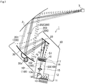
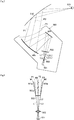
- Fig. 1 is a schematic configuration diagram showing a configuration of a head up display device (hereinafter, referred to as "HUD device") 1 according to this embodiment.
- the HUD device 1 according to this embodiment is provided in a dashboard of a vehicle.
- the HUD device 1 emits an image light 200 toward a windshield 2 of the vehicle.
- the image light 200 reflected by the windshield 2 is directed to an eye box 3.
- the user visually recognizes a virtual image having desired luminance generated by the image light 200.
- the user recognizes the virtual image via the windshield 2 as if the virtual image is located in a distant place while the virtual image is being superposed on a real view in front of the vehicle.
- the HUD device 1 includes a display device 10 for displaying a real image S1 and emitting the image light 200 forming the real image S1, a first reflection unit 20 for reflecting the image light 200 emitted by the display device 10, a second reflection unit 30 for enlarging the image light 200 reflected by the first reflection unit 20 and directing the image light 200 to the windshield 2, a housing 40 storing the above members, and a control unit (not shown) for electrically controlling the HUD device 1.
- the display device 10 includes a light source 11 for emitting irradiation light (not shown), light source mirrors 12, a prism 13, a reflection type display device 14, a projection lens 15, light distribution adjustment means 16, and a transmission type screen 17.
- the display device 10 forms the real image S1 on the transmission type screen 17 and emits the image light 200 forming the real image S1 toward the first reflection unit 20.
- the light source 11 includes, for example, a plurality of LEDs capable of outputting light of red, blue, and green and emits the irradiation light of desired color with desired light intensity at a desired timing under the control of the control unit.
- the display device 10 in this embodiment employs a field sequential color driving method, and the light source 11 of each color emits the irradiation light in time division.
- the light source mirror 12 is, for example, a dichroic mirror for reflecting light having a specific wavelength and transmitting light having the other wavelengths.
- the light source mirror 12 aligns courses of light of red, blue, and green emitted from the plurality of light sources 11 to direct the courses thereof to the prism 13 and causes the irradiation light from the light source 11 to be incident on the prism 13 at a proper angle.
- the prism 13 is provided between the light source mirror 12 and the reflection type display device 14 and has an inclined plane that is inclined at a predetermined angle with respect to an optical axis of the irradiation light incident from the light source mirror 12.
- the irradiation light incident on the inclined plane from the light source mirror 12 is transmitted through the inclined plane and is incident on the reflection type display device 14.
- projection light 100 emitted from the reflection type display device 14 is incident on the prism 13 again and is reflected by the inclined plane toward the projection lens 15, and the projection light 100 is emitted from a projection surface 13a.
- the reflection type display device 14 is, for example, a reflection type display device such as a DMD (Digital Micromirror Device) or an LCOS (registered trademark: Liquid Crystal On Silicon).
- the reflection type display device 14 converts the irradiation light incident from the prism 13 into the projection light 100 for displaying a virtual image under the control of the control unit and reflects the projection light toward the prism 13.
- the projection lens 15 is made up of, for example, a convex lens having a spherical surface and enlarges the projection light 100 incident from the prism 13 and emits the projection light 100 toward the light distribution adjustment means 16.
- the projection lens 15 is an imaging optical system for receiving the projection light 100 from the reflection type display device 14 and forming the real image S1 on the transmission type screen 17 described below.
- the light distribution adjustment means 16 is a biconvex lens having free-form surfaces whose curvatures are different between a first direction X extending in a direction vertical to an optical axis (102) of the projection light and a second direction Y orthogonal to this first direction X and is provided on an optical path of the projection light 100 directed from the projection lens 15 to the transmission type screen 17.
- the light distribution adjustment means 16 adjusts light distribution of the image light 200 emitted from regions of the transmission type screen 17 by refracting the projection light 100 directed from the projection surface 13a to the transmission type screen 17. Specific effects of the light distribution adjustment means 16 will be described in detail below.
- the transmission type screen 17 is, for example, a diffusion film made of resin such as polycarbonate.
- the transmission type screen 17 allows an image of the projection light 100 emitted from the projection lens 15 to be formed as the real image S1 and emits the image light 200 diffused in a constant distribution. Note that light distribution of the image light 200 emitted from the transmission type screen 17 is adjusted in each region of the transmission type screen 17 by effects of the light distribution adjustment means 16.
- the reflection type display device 14 generates the projection light 100 and emits the projection light 100 through the projection surface 13a, and the projection lens 15 forms an image of the projection light 100 on the transmission type screen 17 as the real image S1. Then, the light distribution adjustment means 16 refracts the projection light 100 directed from the projection lens 15 to the transmission type screen 17, thereby adjusting light distribution of the image light 200 emitted from the regions of the transmission type screen 17. Thus, it is possible to efficiently direct the image light 200 in a direction of the eye box 3.
- the first reflection unit 20 is a plane mirror and is obtained by forming a reflective film on a surface of a base made of, for example, a synthetic resin material or glass material by using depositing or other means.
- the first reflection unit 20 reflects the image light 200 diffused by and transmitted through the transmission type screen 17 toward the second reflection unit 30 described below.
- the second reflection unit 30 is a concave mirror and is obtained by forming a reflective film on a surface of a base made of, for example, a synthetic resin material by using depositing or other means.
- the second reflection unit 30 has a reflection surface having a concave free-form surface, and a detailed shape of the surface thereof is calculated on the basis of a positional relationship with the transmission type screen 17, the first reflection unit 20, the windshield 2 (reflection-transmission surface), and the eye box 3, a curvature of the windshield 2, a required imaging distance of the virtual image, an angle of view of the HUD device 1 visually recognized by the user, and the like.
- the second reflection unit 30 can be designed so that distortion of the virtual image is minimized. Further, the second reflection unit 30 enlarges the image light 200 reflected by the first reflection unit 20 and reflects the image light 200 toward the windshield 2.
- the second reflection unit 30 includes an actuator 30a capable of adjusting an angle of the second reflection unit 30.
- the actuator 30a can direct the image light 200 to the eye box 3 by rotating the second reflection unit 30 in accordance with a viewer's point-of-sight position detected by point-of-sight position detection means (not shown) made up of a camera or the like.
- the actuator 30a may rotate the second reflection unit 30 in accordance with operation of an operation unit (not shown).
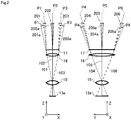
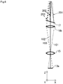
- Fig. 2(a) is a schematic configuration diagram of the light distribution adjustment means 16 seen from the second direction Y
- Fig. 2(b) is a schematic configuration diagram of the light distribution adjustment means 16 seen from the first direction X.
- the projection light 100 (projection light 101, projection light 102, and projection light 103) emitted from the projection surface 13a shown in Fig. 2(a) is light forming a vertical direction of the virtual image visually recognized by the viewer.
- the projection light 101 forms a lower end of the virtual image
- the projection light 102 forms a part in the vicinity of the vertical center of the virtual image
- the projection light 103 forms an upper end of the virtual image.
- the projection light 100 (projection light 101, projection light 102, and projection light 103) emitted from the regions of the projection surface 13a is incident on the light distribution adjustment means 16 via the projection lens 15.
- the light distribution adjustment means 16 refracts the projection light 101, the projection light 102, and the projection light 103 incident on the transmission type screen 17 so that a light distribution axis 201a, a light distribution axis 202a, and a light distribution axis 203a of image light 201, image light 202, and image light 203 emitted from the transmission type screen 17 substantially run along an optical path P1, an optical path P2, and an optical path P3 directed to the eye box 3.
- the light distribution adjustment means 16 largely refracts the projection light 100 (projection light 101 and projection light 103) incident on positions apart from an optical axis of the light distribution adjustment means 16 and emits the projection light 100 toward the transmission type screen 17.
- the light distribution adjustment means 16 inclines the projection light 101 by an angle ⁇ 1 and the projection light 103 by an angle ⁇ 3 toward the optical axis of the light distribution adjustment means 16 and emits the projection light 101 and the projection light 103.
- the projection light 102 along the optical axis of the light distribution adjustment means 16 forms an image on the transmission type screen 17 without being refracted by the light distribution adjustment means 16 (without being adjusted by the light distribution adjustment means 16 in terms of light distribution thereof) and is emitted as the image light 202.
- the light distribution adjustment means 16 increases an adjustment amount (angle to be inclined) of the projection light 100 as the projection light 100 is separated from the optical axis of the light distribution adjustment means 16.
- the projection light 100 (projection light 104, projection light 105, and projection light 106) emitted from the projection surface 13a shown in Fig. 2(b) is light forming a horizontal direction of the virtual image visually recognized by the viewer.
- the projection light 104 forms a right end of the virtual image
- the projection light 105 forms a part in the vicinity of the horizontal center of the virtual image
- the projection light 106 forms a left end of the virtual image.
- the projection light 100 (projection light 104, projection light 105, and projection light 106) emitted from the regions of the projection surface 13a is incident on the light distribution adjustment means 16 via the projection lens 15.
- the light distribution adjustment means 16 refracts the projection light 104, the projection light 105, and the projection light 106 incident on the transmission type screen 17 so that a light distribution axis 204a, a light distribution axis 205a, and a light distribution axis 206a of image light 204, image light 205, and image light 206 emitted from the transmission type screen 17 substantially run along an optical path P4, an optical path P5, and an optical path P6 directed to the eye box 3.
- the light distribution adjustment means 16 In the second direction Y, the light distribution adjustment means 16 largely refracts the projection light 100 (projection light 104 and projection light 106) incident on positions apart from the optical axis of the light distribution adjustment means 16 and emits the projection light 100 toward the transmission type screen 17. Specifically, the light distribution adjustment means 16 inclines the projection light 104 by an angle ⁇ 4 and the projection light 106 by an angle ⁇ 6 toward the optical axis of the light distribution adjustment means 16 and emits the projection light 104 and the projection light 106.
- the projection light 105 along the optical axis of the light distribution adjustment means 16 forms an image on the transmission type screen 17 without being refracted by the light distribution adjustment means 16 (without being adjusted by the light distribution adjustment means 16 in terms of light distribution thereof) and is emitted as the image light 205.
- the light distribution adjustment means 16 increases an adjustment amount (angle to be inclined) of the projection light 100 as the projection light 100 is separated from the optical axis of the light distribution adjustment means 16.
- the angle ⁇ 1 and the angle ⁇ 3 (adjustment amounts) at which the image light 201 and the image light 203 distributed in a vertical direction of the eye box 3 are refracted by the light distribution adjustment means 16 are larger than the angle ⁇ 4 and the angle ⁇ 6 (adjustment amounts) at which the image light 204 and the image light 206 distributed in a horizontal direction of the eye box 3 are refracted.
- light distribution of the image light 200 emitted from the regions of the transmission type screen 17 can be adjusted by the light distribution adjustment means 16, and therefore it is possible to efficiently direct the image light 200 to the eye box 3.
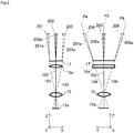
- Fig. 3(a) is a schematic configuration diagram of the light distribution adjustment means 16a seen from the second direction Y
- Fig. 3(b) is a schematic configuration diagram of the light distribution adjustment means 16a seen from the first direction X. Note that, in Fig. 3 , configurations the same as the configurations in the above first embodiment are denoted by the same reference signs, and description thereof will be omitted.
- the HUD device 1 in the second embodiment is different in that the HUD device 1 includes the light distribution adjustment means 16a having a characteristic different from that of the light distribution adjustment means 16 in the above first embodiment.
- the light distribution adjustment means 16a in the second embodiment is a cylindrical lens that has power to refract the projection light 100 in the first direction X and does not have power to refract the projection light 100 in the second direction Y.
- the projection light 100 (projection light 104, projection light 105, and projection light 106) emitted from the regions of the projection surface 13a is incident on the light distribution adjustment means 16a via the projection lens 15.
- the light distribution adjustment means 16a emits the projection light 104, the projection light 105, and the projection light 106 toward the transmission type screen 17 without changing directions of the projection light 104, the projection light 105, and the projection light 106.
- the transmission type screen 17 emits the image light 204, the image light 205, and the image light 206 having the light distribution axis 204a, the light distribution axis 205a, and the light distribution axis 206a whose directions are substantially the same as those of the projection light 104, the projection light 105, and the projection light 106 incident on a back surface thereof.
- projection angles of the projection light 104, the projection light 105, and the projection light 106 from the projection lens 15 are set so that the light distribution axis 204a, the light distribution axis 205a, and the light distribution axis 206a run along the optical path P4, the optical path P5, and the optical path P6 directed to the eye box 3.
- the light distribution adjustment means 16a has power to refract the projection light 100 only in one axial direction (first direction X), and therefore it is possible to facilitate an optical design of the light distribution adjustment means 16a.
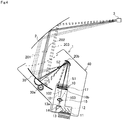
- the HUD device 1 in a third embodiment is different in that the image light 201, the image light 202, and the image light 203 emitted from the regions of the transmission type screen 17 intersect with one another and form an intermediate image S2 at a predetermined position.
- Fig. 4 is a schematic configuration diagram of the HUD device 1 in the third embodiment.
- Fig. 5(a) is a schematic configuration diagram of light distribution adjustment means 16b seen from the second direction Y
- Fig. 5(b) is a schematic configuration diagram of the light distribution adjustment means 16b seen from the first direction X.
- the light distribution adjustment means 16b in the third embodiment is, for example, a cylindrical lens, and an optical region that receives the projection light 100 and emits the refracted projection light 100 toward the transmission type screen 17 is formed to be larger than a region where the transmission type screen 17 forms the real image S1.
- the projection light 100 (projection light 101, projection light 102, and projection light 103) emitted from the regions of the projection surface 13a is incident on the light distribution adjustment means 16b via the projection lens 15.
- the light distribution adjustment means 16b refracts the projection light 101, the projection light 102, and the projection light 103 so that the light distribution axis 201a, the light distribution axis 202a, and the light distribution axis 203a of the image light 201, the image light 202, and the image light 203 emitted from the transmission type screen 17 substantially run along the optical path P1, the optical path P2, and the optical path P3 directed to the eye box 3 and emits the projection light 101, the projection light 102, and the projection light 103 toward the transmission type screen 17.
- the projection light 100 (projection light 101 and projection light 103) incident on positions apart from an optical axis of the light distribution adjustment means 16b is largely refracted and is emitted toward the transmission type screen 17.
- the light distribution adjustment means 16b inclines the projection light 101 and the projection light 103 so that the projection light 101 and the projection light 103 are directed to the optical axis of the light distribution adjustment means 16b and emits the projection light 101 and the projection light 103.
- the whole image light 200 is directed to the first reflection unit 20 while being converged, and therefore a small first reflection unit 20 can receive the image light 200.
- the light distribution adjustment means 16b increases an adjustment amount (angle to be inclined) of the projection light 100 as the projection light 100 is separated from the optical axis of the light distribution adjustment means 16b.
- the first reflection unit 20b is made up of a concave mirror in order to form the intermediate image S2 with the image light 200 emitted from the transmission type screen 17.
- the first reflection unit 20 forms the image light 200 of the real image S1 formed on the transmission type screen 17 as the intermediate image S2 between the first reflection unit 20 and the second reflection unit 30.
- An imaging position of the intermediate image S2 is set to be closer to the second reflection unit 30 than a focal length of the second reflection unit 30 and be in the vicinity of the focal length of the second reflection unit 30. This makes it possible to cause a viewer to visually recognize a high-magnification virtual image.
- the HUD device 1 in the third embodiment directs a light distribution axis 200a of the image light 200 emitted from each region of the transmission type screen 17 to the optical axis of the light distribution adjustment means 16b by using the light distribution adjustment means 16b, and therefore it is possible to efficiently generate the intermediate image S2 with the small first reflection unit 20.
- the light distribution adjustment means 16 for refracting the projection light 100 from the projection lens 15 is a free-form surface lens or a cylindrical lens.
- the light distribution adjustment means 16 is not limited thereto and may be a rotationally symmetric lens or a toroidal lens having a spherical or aspherical surface as appropriate.
- the light distribution adjustment means 16 is made up of a lens.
- the light distribution adjustment means 16 may be made up of a mirror having a concave surface.
- the transmission type screen 17 is a diffusion film.
- the transmission type screen 17 may be made up of a microlens array.
- a magnitude of a light distribution angle and a light distribution direction of the image light 200 emitted from each region of the transmission type screen 17 can be adjusted in each region of the transmission type screen 17. Therefore, it is possible to direct the image light 200 to a viewer more efficiently.
- the transmission type screen 17 is provided to be vertical to the optical axis of the light distribution adjustment means 16.
- the transmission type screen 17 may be inclined with respect to the optical axis of the light distribution adjustment means 16 in the first direction X or/and the second direction Y.
- the reflection-transmission surface onto which the image light 200 is projected is not limited to the windshield 2 of the vehicle.
- the reflection-transmission surface onto which the image light 200 is projected may be, for example, a combiner member provided dedicatedly.
- the invention relates to a head up display device for causing a virtual image superposed on a real view to be visually recognized and is suitable as, for example, a display device for emitting image light toward a windshield of a vehicle, the display device being provided in a dashboard of the vehicle.
- Reference Signs List for causing a virtual image superposed on a real view to be visually recognized and is suitable as, for example, a display device for emitting image light toward a windshield of a vehicle, the display device being provided in a dashboard of the vehicle.
Landscapes
- Engineering & Computer Science (AREA)
- Physics & Mathematics (AREA)
- General Physics & Mathematics (AREA)
- Chemical & Material Sciences (AREA)
- Transportation (AREA)
- Combustion & Propulsion (AREA)
- Mechanical Engineering (AREA)
- Theoretical Computer Science (AREA)
- Computer Hardware Design (AREA)
- Optics & Photonics (AREA)
- Crystallography & Structural Chemistry (AREA)
- Instrument Panels (AREA)
- Liquid Crystal Display Device Control (AREA)
- Control Of Indicators Other Than Cathode Ray Tubes (AREA)
Abstract
Description
- The present invention relates to a head up display device for causing a virtual image superposed on a real view to be visually recognized.
- A conventional head up display (HUD) device is disclosed in
PTL 1. As shown inFigs. 7 and 8 , such an HUD includes aprojector 501 for emitting projection light beams L1, L2, and L3, aprojection lens 502 for causing images of the projection light beams L1, L2, and L3 to be formed on atransmission type screen 503, thetransmission type screen 503 having a back surface that receives the projection light beams L1, L2, and L3 from theprojection lens 502 and forms real images thereof and a front surface that diffuses and emits image light beams forming the real images, and aplane mirror 504 and aconcave mirror 505 for directing image light beams M1, M2, and M3 diffused on thetransmission type screen 503 to a windshield (projection reflection surface) 510 of a vehicle. P1, P2, and P3 shown inFig. 7 and 8 indicate optical paths of the image light beams contributing to a viewer visually recognizing a virtual image. - Projection light L directed from the
projection lens 502 to thetransmission type screen 503 is conically broadened toward thetransmission type screen 503. The projection light beam L1 incident on thetransmission type screen 503 is diffused by thetransmission type screen 503 and is diffused as the image light beam M1 having, as an optical axis, a light distribution axis M1a having the same direction as that of the projection light beam L1. Similarly, the projection light beams L2 and L3 incident on thetransmission type screen 503 are also diffused by thetransmission type screen 503 and are diffused as the image light beams M2 and M3 having, as optical axes, light distribution axes M2a and M3a having the same directions as those of the projection light beams L2 and L3. - PTL 1:
JP-A-2004-126226 - However, in the case where the projection light L from the
projection lens 502 is directly projected onto thetransmission type screen 503 as inPTL 1, the directions of the light distribution axes M1a, M2a, and M3a emitted from thetransmission type screen 503 are substantially the same as those of the projection light beams L1, L2, and L3. Therefore, optical paths of the image light beams M1 and M3 emitted from predetermined regions of thetransmission type screen 503 do not run along the optical paths P1 and P3 directed to a point ofsight 520 of a viewer (the light distribution axes M1a and M3a do not match with the optical paths P1 and P3). Thus, an image light M reaching the point ofsight 520 of the viewer is weak, and therefore luminance of a virtual image visually recognized by the viewer may be reduced. Further, the light distribution axes M1a and M3a of the image light beams M1 and M3 diffused in the respective regions of thetransmission type screen 503 do not run along the optical paths P1 and P3 directed to the point ofsight 520 of the viewer, and therefore light use efficiency of the image light beams M1 and M3 is reduced. - The invention has been made in view of the above circumstances, and an object is to provide a head up display device capable of efficiently directing image light to a viewer.
- In order to achieve the above object, a head up display device of a first invention includes: a projector for emitting projection light forming an image; a screen for allowing an image of the projection light to be formed and diffusing the projection light as image light; an imaging optical system for enlarging the projection light and forming the image of the projection light on the screen; and light distribution adjustment means for adjusting light distribution of the image light emitted from the screen in each region by refracting the projection light, the light distribution adjustment means being provided between the screen and the imaging optical system.
- A head up display device of a second invention is such that the light distribution adjustment means adjusts the image light so that the image light emitted from each region of the screen is directed to an optical axis of the projection light.
- A head up display device of a third invention is such that the light distribution adjustment means increases an adjustment amount of the projection light as the projection light is separated from an optical axis of the projection light in at least a first direction between the first direction and a second direction, the first direction extending in a direction vertical to the optical axis of the projection light and the second direction extending in a direction vertical to the optical axis of the projection light and orthogonal to the first direction.
- According to the invention, it is possible to efficiently direct image light to a viewer.
-
- [
Fig. 1] Fig. 1 is a schematic configuration diagram of a head up display device in a first embodiment of the invention. - [
Fig. 2 ] In the above embodiment,Fig. 2(a) is a schematic configuration diagram of light distribution adjustment means seen from a second direction andFig. 2(b) is a schematic configuration diagram of the light distribution adjustment means seen from a first direction. - [
Fig. 3 ] In a second embodiment,Fig. 3(a) is a schematic configuration diagram of light distribution adjustment means seen from a second direction andFig. 3(b) is a schematic configuration diagram of the light distribution adjustment means seen from a first direction. - [
Fig. 4] Fig. 4 is a schematic configuration diagram of a head up display device in a third embodiment of the invention. - [
Fig. 5 ] In the above embodiment,Fig. 5(a) is a schematic configuration diagram of light distribution adjustment means seen from a second direction andFig. 5(b) is a schematic configuration diagram of the light distribution adjustment means seen from a first direction. - [
Fig. 6] Fig. 6 is a schematic configuration diagram of light distribution adjustment means seen from a second direction in a modification example. - [
Fig. 7] Fig. 7 is a schematic configuration diagram of a head up display device in a conventional example. - [
Fig. 8] Fig. 8 is a schematic configuration diagram of light distribution adjustment means seen from a second direction in the conventional example. - A first embodiment of the invention will be described with reference to the drawings.
-
Fig. 1 is a schematic configuration diagram showing a configuration of a head up display device (hereinafter, referred to as "HUD device") 1 according to this embodiment. TheHUD device 1 according to this embodiment is provided in a dashboard of a vehicle. TheHUD device 1 emits animage light 200 toward awindshield 2 of the vehicle. Theimage light 200 reflected by thewindshield 2 is directed to aneye box 3. In the case where a user's point-of-sight position is in theeye box 3, the user visually recognizes a virtual image having desired luminance generated by theimage light 200. The user recognizes the virtual image via thewindshield 2 as if the virtual image is located in a distant place while the virtual image is being superposed on a real view in front of the vehicle. - As shown in
Fig. 1 , theHUD device 1 includes adisplay device 10 for displaying a real image S1 and emitting theimage light 200 forming the real image S1, afirst reflection unit 20 for reflecting theimage light 200 emitted by thedisplay device 10, asecond reflection unit 30 for enlarging theimage light 200 reflected by thefirst reflection unit 20 and directing theimage light 200 to thewindshield 2, ahousing 40 storing the above members, and a control unit (not shown) for electrically controlling theHUD device 1. - As shown in
Fig. 1 , thedisplay device 10 includes alight source 11 for emitting irradiation light (not shown),light source mirrors 12, aprism 13, a reflection type display device 14, aprojection lens 15, light distribution adjustment means 16, and atransmission type screen 17. Thedisplay device 10 forms the real image S1 on thetransmission type screen 17 and emits theimage light 200 forming the real image S1 toward thefirst reflection unit 20. - The
light source 11 includes, for example, a plurality of LEDs capable of outputting light of red, blue, and green and emits the irradiation light of desired color with desired light intensity at a desired timing under the control of the control unit. Thedisplay device 10 in this embodiment employs a field sequential color driving method, and thelight source 11 of each color emits the irradiation light in time division. - The
light source mirror 12 is, for example, a dichroic mirror for reflecting light having a specific wavelength and transmitting light having the other wavelengths. Thelight source mirror 12 aligns courses of light of red, blue, and green emitted from the plurality oflight sources 11 to direct the courses thereof to theprism 13 and causes the irradiation light from thelight source 11 to be incident on theprism 13 at a proper angle. - The
prism 13 is provided between thelight source mirror 12 and the reflection type display device 14 and has an inclined plane that is inclined at a predetermined angle with respect to an optical axis of the irradiation light incident from thelight source mirror 12. The irradiation light incident on the inclined plane from thelight source mirror 12 is transmitted through the inclined plane and is incident on the reflection type display device 14. Then,projection light 100 emitted from the reflection type display device 14 is incident on theprism 13 again and is reflected by the inclined plane toward theprojection lens 15, and theprojection light 100 is emitted from aprojection surface 13a. - The reflection type display device 14 is, for example, a reflection type display device such as a DMD (Digital Micromirror Device) or an LCOS (registered trademark: Liquid Crystal On Silicon). The reflection type display device 14 converts the irradiation light incident from the
prism 13 into theprojection light 100 for displaying a virtual image under the control of the control unit and reflects the projection light toward theprism 13. - The
projection lens 15 is made up of, for example, a convex lens having a spherical surface and enlarges theprojection light 100 incident from theprism 13 and emits theprojection light 100 toward the light distribution adjustment means 16. Theprojection lens 15 is an imaging optical system for receiving theprojection light 100 from the reflection type display device 14 and forming the real image S1 on thetransmission type screen 17 described below. - As shown in
Fig. 2 , the light distribution adjustment means 16 is a biconvex lens having free-form surfaces whose curvatures are different between a first direction X extending in a direction vertical to an optical axis (102) of the projection light and a second direction Y orthogonal to this first direction X and is provided on an optical path of theprojection light 100 directed from theprojection lens 15 to thetransmission type screen 17. The light distribution adjustment means 16 adjusts light distribution of theimage light 200 emitted from regions of thetransmission type screen 17 by refracting theprojection light 100 directed from theprojection surface 13a to thetransmission type screen 17. Specific effects of the light distribution adjustment means 16 will be described in detail below. - The
transmission type screen 17 is, for example, a diffusion film made of resin such as polycarbonate. Thetransmission type screen 17 allows an image of theprojection light 100 emitted from theprojection lens 15 to be formed as the real image S1 and emits theimage light 200 diffused in a constant distribution. Note that light distribution of theimage light 200 emitted from thetransmission type screen 17 is adjusted in each region of thetransmission type screen 17 by effects of the light distribution adjustment means 16. - In the
display device 10 described above, the reflection type display device 14 generates theprojection light 100 and emits theprojection light 100 through theprojection surface 13a, and theprojection lens 15 forms an image of theprojection light 100 on thetransmission type screen 17 as the real image S1. Then, the light distribution adjustment means 16 refracts theprojection light 100 directed from theprojection lens 15 to thetransmission type screen 17, thereby adjusting light distribution of theimage light 200 emitted from the regions of thetransmission type screen 17. Thus, it is possible to efficiently direct theimage light 200 in a direction of theeye box 3. - The
first reflection unit 20 is a plane mirror and is obtained by forming a reflective film on a surface of a base made of, for example, a synthetic resin material or glass material by using depositing or other means. Thefirst reflection unit 20 reflects theimage light 200 diffused by and transmitted through thetransmission type screen 17 toward thesecond reflection unit 30 described below. - The
second reflection unit 30 is a concave mirror and is obtained by forming a reflective film on a surface of a base made of, for example, a synthetic resin material by using depositing or other means. Thesecond reflection unit 30 has a reflection surface having a concave free-form surface, and a detailed shape of the surface thereof is calculated on the basis of a positional relationship with thetransmission type screen 17, thefirst reflection unit 20, the windshield 2 (reflection-transmission surface), and theeye box 3, a curvature of thewindshield 2, a required imaging distance of the virtual image, an angle of view of theHUD device 1 visually recognized by the user, and the like. Thesecond reflection unit 30 can be designed so that distortion of the virtual image is minimized. Further, thesecond reflection unit 30 enlarges theimage light 200 reflected by thefirst reflection unit 20 and reflects theimage light 200 toward thewindshield 2. - The
second reflection unit 30 includes anactuator 30a capable of adjusting an angle of thesecond reflection unit 30. Theactuator 30a can direct theimage light 200 to theeye box 3 by rotating thesecond reflection unit 30 in accordance with a viewer's point-of-sight position detected by point-of-sight position detection means (not shown) made up of a camera or the like. Theactuator 30a may rotate thesecond reflection unit 30 in accordance with operation of an operation unit (not shown). - Hereinabove, the configuration of the
HUD device 1 in this embodiment has been described. Hereinafter, effects of the light distribution adjustment means 16 will be described with reference toFig. 2. Fig. 2(a) is a schematic configuration diagram of the light distribution adjustment means 16 seen from the second direction Y, andFig. 2(b) is a schematic configuration diagram of the light distribution adjustment means 16 seen from the first direction X. - An effect of the light distribution adjustment means 16, which is obtained by seeing the light distribution adjustment means 16 from the second direction Y, will be described with reference to
Fig. 2(a) . Note that the projection light 100 (projection light 101,projection light 102, and projection light 103) emitted from theprojection surface 13a shown inFig. 2(a) is light forming a vertical direction of the virtual image visually recognized by the viewer. The projection light 101 forms a lower end of the virtual image, the projection light 102 forms a part in the vicinity of the vertical center of the virtual image, and the projection light 103 forms an upper end of the virtual image. - The projection light 100 (
projection light 101,projection light 102, and projection light 103) emitted from the regions of theprojection surface 13a is incident on the light distribution adjustment means 16 via theprojection lens 15. The light distribution adjustment means 16 refracts theprojection light 101, theprojection light 102, and theprojection light 103 incident on thetransmission type screen 17 so that alight distribution axis 201a, alight distribution axis 202a, and alight distribution axis 203a ofimage light 201,image light 202, and image light 203 emitted from thetransmission type screen 17 substantially run along an optical path P1, an optical path P2, and an optical path P3 directed to theeye box 3. - In the first direction X, the light distribution adjustment means 16 largely refracts the projection light 100 (
projection light 101 and projection light 103) incident on positions apart from an optical axis of the light distribution adjustment means 16 and emits theprojection light 100 toward thetransmission type screen 17. Specifically, the light distribution adjustment means 16 inclines theprojection light 101 by an angle θ1 and theprojection light 103 by an angle θ3 toward the optical axis of the light distribution adjustment means 16 and emits theprojection light 101 and theprojection light 103. Note that theprojection light 102 along the optical axis of the light distribution adjustment means 16 forms an image on thetransmission type screen 17 without being refracted by the light distribution adjustment means 16 (without being adjusted by the light distribution adjustment means 16 in terms of light distribution thereof) and is emitted as theimage light 202. The light distribution adjustment means 16 increases an adjustment amount (angle to be inclined) of theprojection light 100 as theprojection light 100 is separated from the optical axis of the light distribution adjustment means 16. - Next, an effect of the light distribution adjustment means 16, which is obtained by seeing the light distribution adjustment means 16 from the first direction X, will be described with reference to
Fig. 2(b) . Note that the projection light 100 (projection light 104,projection light 105, and projection light 106) emitted from theprojection surface 13a shown inFig. 2(b) is light forming a horizontal direction of the virtual image visually recognized by the viewer. The projection light 104 forms a right end of the virtual image, the projection light 105 forms a part in the vicinity of the horizontal center of the virtual image, and the projection light 106 forms a left end of the virtual image. - The projection light 100 (
projection light 104,projection light 105, and projection light 106) emitted from the regions of theprojection surface 13a is incident on the light distribution adjustment means 16 via theprojection lens 15. The light distribution adjustment means 16 refracts theprojection light 104, theprojection light 105, and theprojection light 106 incident on thetransmission type screen 17 so that alight distribution axis 204a, alight distribution axis 205a, and alight distribution axis 206a ofimage light 204,image light 205, and image light 206 emitted from thetransmission type screen 17 substantially run along an optical path P4, an optical path P5, and an optical path P6 directed to theeye box 3. - In the second direction Y, the light distribution adjustment means 16 largely refracts the projection light 100 (
projection light 104 and projection light 106) incident on positions apart from the optical axis of the light distribution adjustment means 16 and emits theprojection light 100 toward thetransmission type screen 17. Specifically, the light distribution adjustment means 16 inclines theprojection light 104 by an angle θ4 and theprojection light 106 by an angle θ6 toward the optical axis of the light distribution adjustment means 16 and emits theprojection light 104 and theprojection light 106. Note that theprojection light 105 along the optical axis of the light distribution adjustment means 16 forms an image on thetransmission type screen 17 without being refracted by the light distribution adjustment means 16 (without being adjusted by the light distribution adjustment means 16 in terms of light distribution thereof) and is emitted as theimage light 205. The light distribution adjustment means 16 increases an adjustment amount (angle to be inclined) of theprojection light 100 as theprojection light 100 is separated from the optical axis of the light distribution adjustment means 16. Note that the angle θ1 and the angle θ3 (adjustment amounts) at which theimage light 201 and theimage light 203 distributed in a vertical direction of theeye box 3 are refracted by the light distribution adjustment means 16 are larger than the angle θ4 and the angle θ6 (adjustment amounts) at which theimage light 204 and theimage light 206 distributed in a horizontal direction of theeye box 3 are refracted. - As described above, according to the
HUD device 1 in this embodiment, light distribution of theimage light 200 emitted from the regions of thetransmission type screen 17 can be adjusted by the light distribution adjustment means 16, and therefore it is possible to efficiently direct theimage light 200 to theeye box 3. - Hereinafter, effects of light distribution adjustment means 16a in a second embodiment will be described with reference to
Fig. 3. Fig. 3(a) is a schematic configuration diagram of the light distribution adjustment means 16a seen from the second direction Y, andFig. 3(b) is a schematic configuration diagram of the light distribution adjustment means 16a seen from the first direction X. Note that, inFig. 3 , configurations the same as the configurations in the above first embodiment are denoted by the same reference signs, and description thereof will be omitted. - The
HUD device 1 in the second embodiment is different in that theHUD device 1 includes the light distribution adjustment means 16a having a characteristic different from that of the light distribution adjustment means 16 in the above first embodiment. The light distribution adjustment means 16a in the second embodiment is a cylindrical lens that has power to refract theprojection light 100 in the first direction X and does not have power to refract theprojection light 100 in the second direction Y. - An effect of the light distribution adjustment means 16, which is obtained by seeing the light distribution adjustment means 16a in the second embodiment from the first direction X, will be described with reference to
Fig. 3(b) . - The projection light 100 (
projection light 104,projection light 105, and projection light 106) emitted from the regions of theprojection surface 13a is incident on the light distribution adjustment means 16a via theprojection lens 15. The light distribution adjustment means 16a emits theprojection light 104, theprojection light 105, and theprojection light 106 toward thetransmission type screen 17 without changing directions of theprojection light 104, theprojection light 105, and theprojection light 106. Thetransmission type screen 17 emits theimage light 204, theimage light 205, and theimage light 206 having thelight distribution axis 204a, thelight distribution axis 205a, and thelight distribution axis 206a whose directions are substantially the same as those of theprojection light 104, theprojection light 105, and theprojection light 106 incident on a back surface thereof. Note that projection angles of theprojection light 104, theprojection light 105, and the projection light 106 from theprojection lens 15 are set so that thelight distribution axis 204a, thelight distribution axis 205a, and thelight distribution axis 206a run along the optical path P4, the optical path P5, and the optical path P6 directed to theeye box 3. - Also in such a configuration, light distribution of the
image light 200 emitted from the regions of thetransmission type screen 17 can be adjusted by the light distribution adjustment means 16a, and therefore it is possible to efficiently direct theimage light 200 to theeye box 3. Further, the light distribution adjustment means 16a has power to refract theprojection light 100 only in one axial direction (first direction X), and therefore it is possible to facilitate an optical design of the light distribution adjustment means 16a. - The
HUD device 1 in a third embodiment is different in that theimage light 201, theimage light 202, and theimage light 203 emitted from the regions of thetransmission type screen 17 intersect with one another and form an intermediate image S2 at a predetermined position. Hereinafter, the third embodiment of the invention will be described with reference toFigs. 4 and5 .Fig. 4 is a schematic configuration diagram of theHUD device 1 in the third embodiment.Fig. 5(a) is a schematic configuration diagram of light distribution adjustment means 16b seen from the second direction Y, andFig. 5(b) is a schematic configuration diagram of the light distribution adjustment means 16b seen from the first direction X. - The light distribution adjustment means 16b in the third embodiment is, for example, a cylindrical lens, and an optical region that receives the
projection light 100 and emits the refractedprojection light 100 toward thetransmission type screen 17 is formed to be larger than a region where thetransmission type screen 17 forms the real image S1. - An effect of the light distribution adjustment means 16b, which is obtained by seeing the light distribution adjustment means 16b from the second direction Y, will be described with reference to
Fig. 5(a) . - The projection light 100 (
projection light 101,projection light 102, and projection light 103) emitted from the regions of theprojection surface 13a is incident on the light distribution adjustment means 16b via theprojection lens 15. The light distribution adjustment means 16b refracts theprojection light 101, theprojection light 102, and theprojection light 103 so that thelight distribution axis 201a, thelight distribution axis 202a, and thelight distribution axis 203a of theimage light 201, theimage light 202, and theimage light 203 emitted from thetransmission type screen 17 substantially run along the optical path P1, the optical path P2, and the optical path P3 directed to theeye box 3 and emits theprojection light 101, theprojection light 102, and theprojection light 103 toward thetransmission type screen 17. - In the first direction X, the projection light 100 (
projection light 101 and projection light 103) incident on positions apart from an optical axis of the light distribution adjustment means 16b is largely refracted and is emitted toward thetransmission type screen 17. Specifically, the light distribution adjustment means 16b inclines theprojection light 101 and theprojection light 103 so that theprojection light 101 and theprojection light 103 are directed to the optical axis of the light distribution adjustment means 16b and emits theprojection light 101 and theprojection light 103. With this, thewhole image light 200 is directed to thefirst reflection unit 20 while being converged, and therefore a smallfirst reflection unit 20 can receive theimage light 200. The light distribution adjustment means 16b increases an adjustment amount (angle to be inclined) of theprojection light 100 as theprojection light 100 is separated from the optical axis of the light distribution adjustment means 16b. - In the
HUD device 1 in the third embodiment, thefirst reflection unit 20b is made up of a concave mirror in order to form the intermediate image S2 with theimage light 200 emitted from thetransmission type screen 17. Thefirst reflection unit 20 forms theimage light 200 of the real image S1 formed on thetransmission type screen 17 as the intermediate image S2 between thefirst reflection unit 20 and thesecond reflection unit 30. An imaging position of the intermediate image S2 is set to be closer to thesecond reflection unit 30 than a focal length of thesecond reflection unit 30 and be in the vicinity of the focal length of thesecond reflection unit 30. This makes it possible to cause a viewer to visually recognize a high-magnification virtual image. - As described above, the
HUD device 1 in the third embodiment directs a light distribution axis 200a of theimage light 200 emitted from each region of thetransmission type screen 17 to the optical axis of the light distribution adjustment means 16b by using the light distribution adjustment means 16b, and therefore it is possible to efficiently generate the intermediate image S2 with the smallfirst reflection unit 20. - The invention is not limited by the above embodiments and the drawings. It is possible to make modification (including deletion of constituent elements) as appropriate without deviating from the scope of the present invention. Hereinafter, modification examples will be described.
- In the above embodiments, the light distribution adjustment means 16 for refracting the projection light 100 from the
projection lens 15 is a free-form surface lens or a cylindrical lens. However, the light distribution adjustment means 16 is not limited thereto and may be a rotationally symmetric lens or a toroidal lens having a spherical or aspherical surface as appropriate. - In the above embodiments, the light distribution adjustment means 16 is made up of a lens. However, the light distribution adjustment means 16 may be made up of a mirror having a concave surface.
- In the above embodiments, the
transmission type screen 17 is a diffusion film. However, thetransmission type screen 17 may be made up of a microlens array. When thetransmission type screen 17 is made up of a microlens array, a magnitude of a light distribution angle and a light distribution direction of theimage light 200 emitted from each region of thetransmission type screen 17 can be adjusted in each region of thetransmission type screen 17. Therefore, it is possible to direct theimage light 200 to a viewer more efficiently. - In the above embodiments, the
transmission type screen 17 is provided to be vertical to the optical axis of the light distribution adjustment means 16. However, as shown inFig. 6 , thetransmission type screen 17 may be inclined with respect to the optical axis of the light distribution adjustment means 16 in the first direction X or/and the second direction Y. With this configuration, it is possible to prevent sunlight entering from the outside of theHUD device 1 from being transmitted through thetransmission type screen 17 to be propagated to thelight source mirror 12 and thelight source 11. - The reflection-transmission surface onto which the
image light 200 is projected is not limited to thewindshield 2 of the vehicle. The reflection-transmission surface onto which theimage light 200 is projected may be, for example, a combiner member provided dedicatedly. - In the above description, in order to easily understand the invention, description of publicly-known unimportant technical matters has been omitted as appropriate.
- The invention relates to a head up display device for causing a virtual image superposed on a real view to be visually recognized and is suitable as, for example, a display device for emitting image light toward a windshield of a vehicle, the display device being provided in a dashboard of the vehicle. Reference Signs List
-
- 1
- HUD device (head up display device)
- 2
- windshield (reflection-transmission surface)
- 3
- eye box
- 10
- display device
- 11
- light source
- 12
- light source mirror
- 13
- prism
- 14
- reflection type display device (projector)
- 15
- projection lens (imaging optical system)
- 16
- light distribution adjustment means
- 17
- transmission type screen (screen)
- 20
- first reflection unit
- 30
- second reflection unit
- 40
- housing
- 100
- projection light
- 200
- image light
Claims (3)
- A head up display device, comprising:a projector for emitting projection light forming an image;a screen for allowing an image of the projection light to be formed and diffusing the projection light as image light;an imaging optical system for enlarging the projection light and forming the image of the projection light on the screen; andlight distribution adjustment means for adjusting light distribution of the image light emitted from the screen in each region by refracting the projection light, the light distribution adjustment means being provided between the screen and the imaging optical system.
- The head up display device according to claim 1, wherein
the light distribution adjustment means adjusts the image light so that the image light emitted from each region of the screen is directed to an optical axis of the projection light. - The head up display device according to claim 1 or 2, wherein
the light distribution adjustment means increases an adjustment amount of the projection light as the projection light is separated from an optical axis of the projection light in at least a first direction between the first direction and a second direction, the first direction extending in a direction vertical to the optical axis of the projection light and the second direction extending in a direction vertical to the optical axis of the projection light and orthogonal to the first direction.
Applications Claiming Priority (2)
| Application Number | Priority Date | Filing Date | Title |
|---|---|---|---|
| JP2014211904A JP6550716B2 (en) | 2014-10-16 | 2014-10-16 | Head-up display device |
| PCT/JP2015/078934 WO2016060119A1 (en) | 2014-10-16 | 2015-10-13 | Head-up display device |
Publications (2)
| Publication Number | Publication Date |
|---|---|
| EP3208648A1 true EP3208648A1 (en) | 2017-08-23 |
| EP3208648A4 EP3208648A4 (en) | 2018-03-28 |
Family
ID=55746663
Family Applications (1)
| Application Number | Title | Priority Date | Filing Date |
|---|---|---|---|
| EP15850928.1A Withdrawn EP3208648A4 (en) | 2014-10-16 | 2015-10-13 | Head-up display device |
Country Status (5)
| Country | Link |
|---|---|
| US (1) | US10549637B2 (en) |
| EP (1) | EP3208648A4 (en) |
| JP (1) | JP6550716B2 (en) |
| CN (1) | CN106796352B (en) |
| WO (1) | WO2016060119A1 (en) |
Families Citing this family (21)
| Publication number | Priority date | Publication date | Assignee | Title |
|---|---|---|---|---|
| JP6558017B2 (en) * | 2015-03-27 | 2019-08-14 | 日本精機株式会社 | Head-up display |
| JP6458998B2 (en) * | 2015-05-13 | 2019-01-30 | 日本精機株式会社 | Head-up display |
| JPWO2017061040A1 (en) * | 2015-10-09 | 2018-08-16 | マクセル株式会社 | Projection optical system and head-up display device |
| JP6551263B2 (en) * | 2016-03-02 | 2019-07-31 | 株式会社デンソー | Head-up display device |
| CN112946898B (en) | 2016-04-26 | 2023-04-28 | 麦克赛尔株式会社 | Automobile |
| WO2017195740A1 (en) * | 2016-05-09 | 2017-11-16 | 日本精機株式会社 | Head-up display device |
| CN109070747B (en) * | 2016-05-10 | 2021-09-14 | 日本精机株式会社 | Head-up display device |
| JP2017219755A (en) * | 2016-06-09 | 2017-12-14 | 株式会社ジャパンディスプレイ | Display device and display method thereof |
| JPWO2019093496A1 (en) * | 2017-11-10 | 2020-12-10 | コニカミノルタ株式会社 | Virtual image projection optical system and display device |
| JP7233008B2 (en) | 2017-12-11 | 2023-03-06 | パナソニックIpマネジメント株式会社 | Head-up displays and moving objects with head-up displays |
| JP7140504B2 (en) * | 2018-02-14 | 2022-09-21 | 矢崎総業株式会社 | projection display |
| JP6914484B2 (en) * | 2018-03-14 | 2021-08-04 | オムロン株式会社 | Photoelectric sensor and sensor system |
| DE102018204274A1 (en) * | 2018-03-20 | 2019-09-26 | Bayerische Motoren Werke Aktiengesellschaft | Projection arrangement for generating a floating projection display in the interior of a motor vehicle |
| JP2019215495A (en) * | 2018-06-14 | 2019-12-19 | パイオニア株式会社 | Display unit |
| CN109375459B (en) * | 2018-12-10 | 2024-01-23 | 杭州炽云科技有限公司 | Virtual image imaging system using free-form surface |
| CN109709675B (en) * | 2019-02-26 | 2021-11-19 | 京东方科技集团股份有限公司 | Augmented reality display device and augmented reality glasses |
| WO2020250896A1 (en) * | 2019-06-13 | 2020-12-17 | 日本精機株式会社 | Head-up display |
| JP7018922B2 (en) * | 2019-12-04 | 2022-02-14 | マクセル株式会社 | Head-up display device |
| WO2024053543A1 (en) * | 2022-09-06 | 2024-03-14 | 株式会社小糸製作所 | Image projection device |
| JP2024162606A (en) | 2023-05-11 | 2024-11-21 | 日本精機株式会社 | Head-up display device |
| WO2025230054A1 (en) * | 2024-04-30 | 2025-11-06 | 엘지전자 주식회사 | Head-up display |
Family Cites Families (15)
| Publication number | Priority date | Publication date | Assignee | Title |
|---|---|---|---|---|
| US6034823A (en) * | 1997-02-07 | 2000-03-07 | Olympus Optical Co., Ltd. | Decentered prism optical system |
| JP3888486B2 (en) * | 1997-07-25 | 2007-03-07 | フジノン株式会社 | Projection display |
| JP2004126226A (en) * | 2002-10-02 | 2004-04-22 | Denso Corp | Head-up display |
| JP5145710B2 (en) | 2006-12-18 | 2013-02-20 | 日本精機株式会社 | Head-up display device |
| JP2009150947A (en) * | 2007-12-19 | 2009-07-09 | Hitachi Ltd | Head-up display device for vehicle |
| JP4852062B2 (en) * | 2008-03-28 | 2012-01-11 | 株式会社東芝 | Monocular image display device and monocular image display method |
| JP4686586B2 (en) * | 2008-09-19 | 2011-05-25 | 株式会社東芝 | In-vehicle display device and display method |
| JP5793639B2 (en) * | 2010-04-20 | 2015-10-14 | パナソニックIpマネジメント株式会社 | See-through display and head-up display |
| CN101876753B (en) * | 2010-06-03 | 2012-06-27 | 香港应用科技研究院有限公司 | Hybrid illumination system for head-up display |
| JP5287828B2 (en) * | 2010-10-26 | 2013-09-11 | 株式会社デンソー | Head-up display device |
| JP5674032B2 (en) * | 2011-03-25 | 2015-02-18 | 日本精機株式会社 | Head-up display device |
| JP5370427B2 (en) * | 2011-07-24 | 2013-12-18 | 株式会社デンソー | Head-up display device |
| CN102736249B (en) * | 2012-06-12 | 2015-07-01 | 广东翼卡车联网服务有限公司 | On-vehicle transparent head-up display system and control method thereof |
| JP6036482B2 (en) * | 2013-03-29 | 2016-11-30 | 株式会社Jvcケンウッド | Image display device |
| CN103487941A (en) * | 2013-09-23 | 2014-01-01 | 苏州佳视特信息科技有限公司 | Automobile information display method and device |
-
2014
- 2014-10-16 JP JP2014211904A patent/JP6550716B2/en active Active
-
2015
- 2015-10-13 US US15/518,571 patent/US10549637B2/en active Active
- 2015-10-13 EP EP15850928.1A patent/EP3208648A4/en not_active Withdrawn
- 2015-10-13 WO PCT/JP2015/078934 patent/WO2016060119A1/en not_active Ceased
- 2015-10-13 CN CN201580055616.1A patent/CN106796352B/en active Active
Also Published As
| Publication number | Publication date |
|---|---|
| CN106796352B (en) | 2020-06-09 |
| US20170225568A1 (en) | 2017-08-10 |
| EP3208648A4 (en) | 2018-03-28 |
| JP2016080860A (en) | 2016-05-16 |
| US10549637B2 (en) | 2020-02-04 |
| JP6550716B2 (en) | 2019-07-31 |
| WO2016060119A1 (en) | 2016-04-21 |
| CN106796352A (en) | 2017-05-31 |
Similar Documents
| Publication | Publication Date | Title |
|---|---|---|
| US10549637B2 (en) | Head-up display device | |
| US10901209B2 (en) | Head-up display device | |
| US10120189B2 (en) | Heads-up display device | |
| US10031403B2 (en) | Device for projecting an image into a display area, having a screen for displaying an intermediate image | |
| EP3415973B1 (en) | Display device and head-up display | |
| CN104254800B (en) | Image generation system and image generation method | |
| US10634909B2 (en) | Display device and head-up display | |
| US20180210200A1 (en) | Head-up display device | |
| US10942352B2 (en) | Head-up display apparatus | |
| JP2016061978A (en) | Head-up display device | |
| JP2020177221A (en) | Far visual point aerial image projection device | |
| JP2017142284A (en) | Display device and head-up display | |
| EP4105703A1 (en) | Illumination system and projection device | |
| US20200257114A1 (en) | Head-up display | |
| JP4625945B2 (en) | Image display device | |
| US8182098B2 (en) | Projection optical system | |
| JP2020024436A (en) | Optical system, image display device, and object device |
Legal Events
| Date | Code | Title | Description |
|---|---|---|---|
| STAA | Information on the status of an ep patent application or granted ep patent |
Free format text: STATUS: THE INTERNATIONAL PUBLICATION HAS BEEN MADE |
|
| PUAI | Public reference made under article 153(3) epc to a published international application that has entered the european phase |
Free format text: ORIGINAL CODE: 0009012 |
|
| STAA | Information on the status of an ep patent application or granted ep patent |
Free format text: STATUS: REQUEST FOR EXAMINATION WAS MADE |
|
| 17P | Request for examination filed |
Effective date: 20170404 |
|
| AK | Designated contracting states |
Kind code of ref document: A1 Designated state(s): AL AT BE BG CH CY CZ DE DK EE ES FI FR GB GR HR HU IE IS IT LI LT LU LV MC MK MT NL NO PL PT RO RS SE SI SK SM TR |
|
| AX | Request for extension of the european patent |
Extension state: BA ME |
|
| DAV | Request for validation of the european patent (deleted) | ||
| DAX | Request for extension of the european patent (deleted) | ||
| A4 | Supplementary search report drawn up and despatched |
Effective date: 20180226 |
|
| RIC1 | Information provided on ipc code assigned before grant |
Ipc: G02B 27/01 20060101AFI20180220BHEP Ipc: B60K 35/00 20060101ALI20180220BHEP Ipc: G09G 3/36 20060101ALI20180220BHEP Ipc: G09G 3/20 20060101ALI20180220BHEP Ipc: G09G 3/34 20060101ALI20180220BHEP |
|
| STAA | Information on the status of an ep patent application or granted ep patent |
Free format text: STATUS: EXAMINATION IS IN PROGRESS |
|
| 17Q | First examination report despatched |
Effective date: 20181123 |
|
| STAA | Information on the status of an ep patent application or granted ep patent |
Free format text: STATUS: THE APPLICATION IS DEEMED TO BE WITHDRAWN |
|
| 18D | Application deemed to be withdrawn |
Effective date: 20211001 |