EP3208464B1 - Centrifugal pump - Google Patents
Centrifugal pump Download PDFInfo
- Publication number
- EP3208464B1 EP3208464B1 EP17150835.1A EP17150835A EP3208464B1 EP 3208464 B1 EP3208464 B1 EP 3208464B1 EP 17150835 A EP17150835 A EP 17150835A EP 3208464 B1 EP3208464 B1 EP 3208464B1
- Authority
- EP
- European Patent Office
- Prior art keywords
- bearing
- centrifugal pump
- pump according
- spoke
- counter
- Prior art date
- Legal status (The legal status is an assumption and is not a legal conclusion. Google has not performed a legal analysis and makes no representation as to the accuracy of the status listed.)
- Active
Links
- 230000007704 transition Effects 0.000 claims description 16
- 239000000463 material Substances 0.000 claims description 10
- 239000004033 plastic Substances 0.000 claims description 7
- 229920003023 plastic Polymers 0.000 claims description 7
- 229910000831 Steel Inorganic materials 0.000 claims description 6
- 239000010959 steel Substances 0.000 claims description 6
- 239000002826 coolant Substances 0.000 claims description 5
- 230000010355 oscillation Effects 0.000 claims description 3
- OKTJSMMVPCPJKN-UHFFFAOYSA-N Carbon Chemical compound [C] OKTJSMMVPCPJKN-UHFFFAOYSA-N 0.000 claims 1
- 229910052799 carbon Inorganic materials 0.000 claims 1
- 229910010293 ceramic material Inorganic materials 0.000 claims 1
- 239000000835 fiber Substances 0.000 claims 1
- 238000002955 isolation Methods 0.000 claims 1
- 239000000498 cooling water Substances 0.000 description 6
- 238000002485 combustion reaction Methods 0.000 description 4
- 238000013016 damping Methods 0.000 description 4
- 239000000919 ceramic Substances 0.000 description 3
- 238000001035 drying Methods 0.000 description 3
- 229920000049 Carbon (fiber) Polymers 0.000 description 2
- 239000004734 Polyphenylene sulfide Substances 0.000 description 2
- 229910052782 aluminium Inorganic materials 0.000 description 2
- XAGFODPZIPBFFR-UHFFFAOYSA-N aluminium Chemical compound [Al] XAGFODPZIPBFFR-UHFFFAOYSA-N 0.000 description 2
- 239000004917 carbon fiber Substances 0.000 description 2
- 210000000078 claw Anatomy 0.000 description 2
- 230000000694 effects Effects 0.000 description 2
- 229920000069 polyphenylene sulfide Polymers 0.000 description 2
- 238000004804 winding Methods 0.000 description 2
- 229910000760 Hardened steel Inorganic materials 0.000 description 1
- 238000005299 abrasion Methods 0.000 description 1
- 238000001816 cooling Methods 0.000 description 1
- 238000011161 development Methods 0.000 description 1
- 230000018109 developmental process Effects 0.000 description 1
- 230000017525 heat dissipation Effects 0.000 description 1
- 238000004519 manufacturing process Methods 0.000 description 1
- 239000007769 metal material Substances 0.000 description 1
- VNWKTOKETHGBQD-UHFFFAOYSA-N methane Chemical compound C VNWKTOKETHGBQD-UHFFFAOYSA-N 0.000 description 1
- 230000035939 shock Effects 0.000 description 1
Images


Classifications
-
- F—MECHANICAL ENGINEERING; LIGHTING; HEATING; WEAPONS; BLASTING
- F04—POSITIVE - DISPLACEMENT MACHINES FOR LIQUIDS; PUMPS FOR LIQUIDS OR ELASTIC FLUIDS
- F04D—NON-POSITIVE-DISPLACEMENT PUMPS
- F04D29/00—Details, component parts, or accessories
- F04D29/66—Combating cavitation, whirls, noise, vibration or the like; Balancing
- F04D29/669—Combating cavitation, whirls, noise, vibration or the like; Balancing especially adapted for liquid pumps
-
- F—MECHANICAL ENGINEERING; LIGHTING; HEATING; WEAPONS; BLASTING
- F16—ENGINEERING ELEMENTS AND UNITS; GENERAL MEASURES FOR PRODUCING AND MAINTAINING EFFECTIVE FUNCTIONING OF MACHINES OR INSTALLATIONS; THERMAL INSULATION IN GENERAL
- F16C—SHAFTS; FLEXIBLE SHAFTS; ELEMENTS OR CRANKSHAFT MECHANISMS; ROTARY BODIES OTHER THAN GEARING ELEMENTS; BEARINGS
- F16C23/00—Bearings for exclusively rotary movement adjustable for aligning or positioning
- F16C23/02—Sliding-contact bearings
- F16C23/04—Sliding-contact bearings self-adjusting
- F16C23/043—Sliding-contact bearings self-adjusting with spherical surfaces, e.g. spherical plain bearings
- F16C23/048—Sliding-contact bearings self-adjusting with spherical surfaces, e.g. spherical plain bearings for axial load mainly
-
- F—MECHANICAL ENGINEERING; LIGHTING; HEATING; WEAPONS; BLASTING
- F04—POSITIVE - DISPLACEMENT MACHINES FOR LIQUIDS; PUMPS FOR LIQUIDS OR ELASTIC FLUIDS
- F04D—NON-POSITIVE-DISPLACEMENT PUMPS
- F04D13/00—Pumping installations or systems
- F04D13/02—Units comprising pumps and their driving means
- F04D13/06—Units comprising pumps and their driving means the pump being electrically driven
- F04D13/0606—Canned motor pumps
- F04D13/0633—Details of the bearings
-
- F—MECHANICAL ENGINEERING; LIGHTING; HEATING; WEAPONS; BLASTING
- F04—POSITIVE - DISPLACEMENT MACHINES FOR LIQUIDS; PUMPS FOR LIQUIDS OR ELASTIC FLUIDS
- F04D—NON-POSITIVE-DISPLACEMENT PUMPS
- F04D1/00—Radial-flow pumps, e.g. centrifugal pumps; Helico-centrifugal pumps
-
- F—MECHANICAL ENGINEERING; LIGHTING; HEATING; WEAPONS; BLASTING
- F04—POSITIVE - DISPLACEMENT MACHINES FOR LIQUIDS; PUMPS FOR LIQUIDS OR ELASTIC FLUIDS
- F04D—NON-POSITIVE-DISPLACEMENT PUMPS
- F04D13/00—Pumping installations or systems
- F04D13/02—Units comprising pumps and their driving means
- F04D13/06—Units comprising pumps and their driving means the pump being electrically driven
- F04D13/0653—Units comprising pumps and their driving means the pump being electrically driven the motor being flooded
-
- F—MECHANICAL ENGINEERING; LIGHTING; HEATING; WEAPONS; BLASTING
- F04—POSITIVE - DISPLACEMENT MACHINES FOR LIQUIDS; PUMPS FOR LIQUIDS OR ELASTIC FLUIDS
- F04D—NON-POSITIVE-DISPLACEMENT PUMPS
- F04D29/00—Details, component parts, or accessories
-
- F—MECHANICAL ENGINEERING; LIGHTING; HEATING; WEAPONS; BLASTING
- F04—POSITIVE - DISPLACEMENT MACHINES FOR LIQUIDS; PUMPS FOR LIQUIDS OR ELASTIC FLUIDS
- F04D—NON-POSITIVE-DISPLACEMENT PUMPS
- F04D29/00—Details, component parts, or accessories
- F04D29/02—Selection of particular materials
- F04D29/026—Selection of particular materials especially adapted for liquid pumps
-
- F—MECHANICAL ENGINEERING; LIGHTING; HEATING; WEAPONS; BLASTING
- F04—POSITIVE - DISPLACEMENT MACHINES FOR LIQUIDS; PUMPS FOR LIQUIDS OR ELASTIC FLUIDS
- F04D—NON-POSITIVE-DISPLACEMENT PUMPS
- F04D29/00—Details, component parts, or accessories
- F04D29/04—Shafts or bearings, or assemblies thereof
- F04D29/041—Axial thrust balancing
- F04D29/0413—Axial thrust balancing hydrostatic; hydrodynamic thrust bearings
-
- F—MECHANICAL ENGINEERING; LIGHTING; HEATING; WEAPONS; BLASTING
- F04—POSITIVE - DISPLACEMENT MACHINES FOR LIQUIDS; PUMPS FOR LIQUIDS OR ELASTIC FLUIDS
- F04D—NON-POSITIVE-DISPLACEMENT PUMPS
- F04D29/00—Details, component parts, or accessories
- F04D29/04—Shafts or bearings, or assemblies thereof
- F04D29/043—Shafts
-
- F—MECHANICAL ENGINEERING; LIGHTING; HEATING; WEAPONS; BLASTING
- F04—POSITIVE - DISPLACEMENT MACHINES FOR LIQUIDS; PUMPS FOR LIQUIDS OR ELASTIC FLUIDS
- F04D—NON-POSITIVE-DISPLACEMENT PUMPS
- F04D29/00—Details, component parts, or accessories
- F04D29/04—Shafts or bearings, or assemblies thereof
- F04D29/046—Bearings
- F04D29/0465—Ceramic bearing designs
-
- F—MECHANICAL ENGINEERING; LIGHTING; HEATING; WEAPONS; BLASTING
- F04—POSITIVE - DISPLACEMENT MACHINES FOR LIQUIDS; PUMPS FOR LIQUIDS OR ELASTIC FLUIDS
- F04D—NON-POSITIVE-DISPLACEMENT PUMPS
- F04D29/00—Details, component parts, or accessories
- F04D29/04—Shafts or bearings, or assemblies thereof
- F04D29/046—Bearings
- F04D29/0467—Spherical bearings
-
- F—MECHANICAL ENGINEERING; LIGHTING; HEATING; WEAPONS; BLASTING
- F04—POSITIVE - DISPLACEMENT MACHINES FOR LIQUIDS; PUMPS FOR LIQUIDS OR ELASTIC FLUIDS
- F04D—NON-POSITIVE-DISPLACEMENT PUMPS
- F04D29/00—Details, component parts, or accessories
- F04D29/40—Casings; Connections of working fluid
- F04D29/42—Casings; Connections of working fluid for radial or helico-centrifugal pumps
- F04D29/426—Casings; Connections of working fluid for radial or helico-centrifugal pumps especially adapted for liquid pumps
- F04D29/4273—Casings; Connections of working fluid for radial or helico-centrifugal pumps especially adapted for liquid pumps suction eyes
-
- F—MECHANICAL ENGINEERING; LIGHTING; HEATING; WEAPONS; BLASTING
- F16—ENGINEERING ELEMENTS AND UNITS; GENERAL MEASURES FOR PRODUCING AND MAINTAINING EFFECTIVE FUNCTIONING OF MACHINES OR INSTALLATIONS; THERMAL INSULATION IN GENERAL
- F16C—SHAFTS; FLEXIBLE SHAFTS; ELEMENTS OR CRANKSHAFT MECHANISMS; ROTARY BODIES OTHER THAN GEARING ELEMENTS; BEARINGS
- F16C17/00—Sliding-contact bearings for exclusively rotary movement
- F16C17/04—Sliding-contact bearings for exclusively rotary movement for axial load only
-
- F—MECHANICAL ENGINEERING; LIGHTING; HEATING; WEAPONS; BLASTING
- F05—INDEXING SCHEMES RELATING TO ENGINES OR PUMPS IN VARIOUS SUBCLASSES OF CLASSES F01-F04
- F05D—INDEXING SCHEME FOR ASPECTS RELATING TO NON-POSITIVE-DISPLACEMENT MACHINES OR ENGINES, GAS-TURBINES OR JET-PROPULSION PLANTS
- F05D2230/00—Manufacture
- F05D2230/20—Manufacture essentially without removing material
- F05D2230/24—Manufacture essentially without removing material by extrusion
-
- F—MECHANICAL ENGINEERING; LIGHTING; HEATING; WEAPONS; BLASTING
- F05—INDEXING SCHEMES RELATING TO ENGINES OR PUMPS IN VARIOUS SUBCLASSES OF CLASSES F01-F04
- F05D—INDEXING SCHEME FOR ASPECTS RELATING TO NON-POSITIVE-DISPLACEMENT MACHINES OR ENGINES, GAS-TURBINES OR JET-PROPULSION PLANTS
- F05D2250/00—Geometry
- F05D2250/70—Shape
- F05D2250/71—Shape curved
- F05D2250/711—Shape curved convex
-
- F—MECHANICAL ENGINEERING; LIGHTING; HEATING; WEAPONS; BLASTING
- F05—INDEXING SCHEMES RELATING TO ENGINES OR PUMPS IN VARIOUS SUBCLASSES OF CLASSES F01-F04
- F05D—INDEXING SCHEME FOR ASPECTS RELATING TO NON-POSITIVE-DISPLACEMENT MACHINES OR ENGINES, GAS-TURBINES OR JET-PROPULSION PLANTS
- F05D2250/00—Geometry
- F05D2250/70—Shape
- F05D2250/71—Shape curved
- F05D2250/712—Shape curved concave
-
- F—MECHANICAL ENGINEERING; LIGHTING; HEATING; WEAPONS; BLASTING
- F05—INDEXING SCHEMES RELATING TO ENGINES OR PUMPS IN VARIOUS SUBCLASSES OF CLASSES F01-F04
- F05D—INDEXING SCHEME FOR ASPECTS RELATING TO NON-POSITIVE-DISPLACEMENT MACHINES OR ENGINES, GAS-TURBINES OR JET-PROPULSION PLANTS
- F05D2300/00—Materials; Properties thereof
- F05D2300/10—Metals, alloys or intermetallic compounds
- F05D2300/17—Alloys
- F05D2300/171—Steel alloys
-
- F—MECHANICAL ENGINEERING; LIGHTING; HEATING; WEAPONS; BLASTING
- F05—INDEXING SCHEMES RELATING TO ENGINES OR PUMPS IN VARIOUS SUBCLASSES OF CLASSES F01-F04
- F05D—INDEXING SCHEME FOR ASPECTS RELATING TO NON-POSITIVE-DISPLACEMENT MACHINES OR ENGINES, GAS-TURBINES OR JET-PROPULSION PLANTS
- F05D2300/00—Materials; Properties thereof
- F05D2300/10—Metals, alloys or intermetallic compounds
- F05D2300/17—Alloys
- F05D2300/173—Aluminium alloys, e.g. AlCuMgPb
-
- F—MECHANICAL ENGINEERING; LIGHTING; HEATING; WEAPONS; BLASTING
- F05—INDEXING SCHEMES RELATING TO ENGINES OR PUMPS IN VARIOUS SUBCLASSES OF CLASSES F01-F04
- F05D—INDEXING SCHEME FOR ASPECTS RELATING TO NON-POSITIVE-DISPLACEMENT MACHINES OR ENGINES, GAS-TURBINES OR JET-PROPULSION PLANTS
- F05D2300/00—Materials; Properties thereof
- F05D2300/20—Oxide or non-oxide ceramics
-
- F—MECHANICAL ENGINEERING; LIGHTING; HEATING; WEAPONS; BLASTING
- F16—ENGINEERING ELEMENTS AND UNITS; GENERAL MEASURES FOR PRODUCING AND MAINTAINING EFFECTIVE FUNCTIONING OF MACHINES OR INSTALLATIONS; THERMAL INSULATION IN GENERAL
- F16C—SHAFTS; FLEXIBLE SHAFTS; ELEMENTS OR CRANKSHAFT MECHANISMS; ROTARY BODIES OTHER THAN GEARING ELEMENTS; BEARINGS
- F16C11/00—Pivots; Pivotal connections
- F16C11/04—Pivotal connections
- F16C11/06—Ball-joints; Other joints having more than one degree of angular freedom, i.e. universal joints
- F16C11/0661—Ball-joints; Other joints having more than one degree of angular freedom, i.e. universal joints the two co-operative parts each having both convex and concave interfaces
-
- F—MECHANICAL ENGINEERING; LIGHTING; HEATING; WEAPONS; BLASTING
- F16—ENGINEERING ELEMENTS AND UNITS; GENERAL MEASURES FOR PRODUCING AND MAINTAINING EFFECTIVE FUNCTIONING OF MACHINES OR INSTALLATIONS; THERMAL INSULATION IN GENERAL
- F16C—SHAFTS; FLEXIBLE SHAFTS; ELEMENTS OR CRANKSHAFT MECHANISMS; ROTARY BODIES OTHER THAN GEARING ELEMENTS; BEARINGS
- F16C2360/00—Engines or pumps
- F16C2360/44—Centrifugal pumps
Definitions
- the invention relates to a centrifugal pump (1), in particular for conveying coolant in vehicles, comprising a pump housing made of a moldable material, comprising a pump head (16) having a suction nozzle (2), a discharge nozzle (3), at least one spoke (11 ) and a bearing support (12) is integral, in which a counter bearing (10) is mounted, wherein a first portion (4) of an axis (5) is supported, about which a pump impeller (6) via a pump impeller (6) fixed Plain bearing (7) is rotatably mounted, wherein the at least one spoke (11) holds the bearing support (12) in a central position within the pump head (16), and with a split pot (30) which separates a wet space of a drying room and in in which a second area (28) of the axle (5) is supported, wherein a wound stator (19) in the dry space and a permanent magnet rotor (20) of an electronically commutated DC motor are received in the wet space i St and the permanent magnet rotor (20)
- main cooling water pump In internal combustion engines in the automotive sector, mechanical centrifugal pumps driven by the crankshaft via a toothed belt are generally present as the main cooling water pump.
- auxiliary electric cooling water pumps are used, which are generally designed as electronically commutated direct current motors. Since these are arranged in the immediate vicinity or directly on the internal combustion engine, they are exposed to the high temperatures and vibration loads of the internal combustion engine. Additional vibrations can be generated by the electric motor and the hydraulic part of the cooling water pump itself. Even main cooling water pumps can be electrically operated and have the same problems. Even with electric vehicles cooling water pumps are required, which z. B. provide for a battery cooling.
- a generic cooling water pump in which a pump impeller is rotatably mounted on a central axis, which is supported and fixed on the one hand in a containment shell and on the other hand in a pump head.
- a hollow cylindrical sliding bearing is part of the pump impeller, which slide bearing can be supported axially on flat end faces of abutments.
- One of the counter bearings is accommodated in the pump head in a bearing carrier, which is connected via straight spokes to the pump head. Vibrations that occur during operation are transmitted in this way largely unattenuated from the pump impeller to the pump head. Furthermore, noises occur due to fluctuations in the radial position of the pump impeller about the axis.
- a centrifugal pump for the promotion of coolant in vehicles, with a made of urformbarem material pump housing, consisting of a pump head, which is integral with a suction nozzle, a discharge nozzle, a spoke and a bearing carrier, in which an abutment is mounted, wherein a supported first portion of an axis about which a pump impeller is rotatably supported via a slide bearing fixed in the impeller bearing, wherein the spoke holds the bearing support in a central position within the pump head and with a split pot, which separates a wet room from a drying room and in which second region of the axis is supported, wherein a wound stator is received in the dry space and a permanent magnet rotor of an electronically commutated DC motor is received in the wet space and the permanent magnet rotor with the pump impeller forms a structural unit, wherein the sliding bearing is a innenzylinderm An antifriction bearing surface and a
- the object of the invention is therefore to provide in a generic centrifugal pump for centering the pump impeller and for damping vibrations, which are transmitted from the pump impeller to the pump head and thus the housing of the centrifugal pump, whereby unpleasant noise should be largely avoided.
- a convex or concave axial bearing surface of the sliding bearing cooperates with a concave or convex counter-bearing surface of an abutment and causes a self-centering of the pump impeller within the pump chamber.
- the vibrations generated in addition are damped by at least one oscillation direction change between the bearing carrier and the suction nozzle.
- vibration energy is converted by internal friction into heat energy and transported away by the coolant. In this way, unpleasant noises are largely avoided or dampened. Every change of direction causes a damping of vibrations. Changes in direction express themselves by turning points in curves. Therefore, it is proposed that the spokes between the bearing carrier and the suction nozzle describe a curve with at least one inflection point.
- This effect is achieved in particular when the first transition region does not axially overlap with the second transition region.
- spokes project substantially radially out of the suction nozzle and pass axially into the bearing carrier. As a result, at least one direction change for the vibration propagation is achieved by about 90 °.
- the thrust bearing surface of the journal bearing should be convex and the abutment surface of the thrust bearing should be concave. It is also conceivable to form the axial bearing surface of the sliding bearing concave and the counter bearing surface of the thrust bearing convex.
- a convex thrust bearing surface or a convex abutment surface is designed as a ball ring section, which is followed by a hollow cylindrical inner surface and a cylindrical outer surface.
- a second embodiment of the invention provides that the sliding bearing and / or the anvil has / have an annular collar, which serve as an axial stop.
- the radii of the thrust bearing surfaces of the sliding bearing and the thrust bearing slightly differ from each other, so that a contact preferably in the near-axis Area occurs.
- the friction radius is lower, whereby a lower mechanical resistance occurs.
- the contact surface is smaller than at the same radii, so that manufacturing inaccuracies can have less negative impact. Wear over the service life can increase the contact surfaces.
- the sliding bearing (7) and / or the anvil (10) are joined by archetypes. This results in a very strong and intimate connection.
- the sliding bearing (7) and / or the anvil (10) has a knurling on the outer circumference. As a result, the surrounding material can connect even better with the original bearing in the respective camp.
- the plain bearing (7) and the anvil (10) different material combinations can be used, for.
- Carbon fiber plastic has proven to be a suitable plastic material, in particular polyphenylene sulfide (PPS) with 30% carbon fibers.
- PPS polyphenylene sulfide
- the bearing is usually made by cold forming. To achieve a high abrasion resistance, this bearing can be designed as a hardened steel bearing.
- the pump head can be made of injection-processable plastic material or higher demands on the strength and heat dissipation properties of a die-cast metal material, such as aluminum (die-cast aluminum) exist.
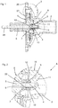
- Fig. 1 shows a sectional view with the essential parts of the invention for a centrifugal pump.
- the sliding bearing 7 has on its end face a convex spherical axial bearing surface 9, which mates with a concave abutment surface 23 of the thrust bearing 10 and cooperates.
- the anvil 10 is mounted in the bearing bracket 12 and serves both the axial bearing and the centering of the pump impeller 6.
- the impeller 6 is shown here without a permanent magnet, which connects directly to an impeller 27.
- the axis 5 is supported on a first region 4 in the bearing support 12 and on a further, second region 28 in a containment shell not visible here.
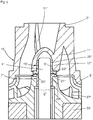
- Fig. 2 shows the storage area of detail A.
- Fig. 1 slightly enlarged, with the pump head 16, the suction nozzle 2, the spoke 11, the bearing support 12, the axis 5, with its first region (end portion) 4, the sliding bearing 7, the anvil 10, the pump impeller 6. More clearly than in Fig. 1 Here are the radial bearing surface 8, and the spherical thrust bearing surface 9 of the sliding bearing 7 and the concave counter-bearing surface 23 of the thrust bearing 10 can be seen.
- Fig. 3 shows a known from the prior art centrifugal pump 1 ', with a pump head 16', which comprises a suction nozzle 2 ', spokes 11', a bearing support 12 'and a Pumpenkopfflansch 26', a split pot 30 ', which a pot bottom 29', a split tube 17 ', a split-top flange 31' and an axle receptacle 18 'projecting from the bottom of the pot 29' comprises a pump impeller 6 'which comprises a magnet ring 33' and an adjoining impeller 27 'and a sliding bearing 7', a stator 19 ', a permanent magnet rotor 20,' a circuit board 35 'and a stator housing 32'.
- the stator 19 'and the printed circuit board 35' are received in a drying space, which is bounded by the split pot 30 'and the stator housing 32'.
- the stator consists of a ring winding 36 'and claw pole plates 37'.
- the pump impeller 6 ' is in one of the pump head 16' and the gap tube 30 'formed pump chamber 34' rotatably received on an axis 5 ', which is received and supported in the axle 18' and the bearing support 12 '.
- In the bearing bracket 12 ' is an abutment 10' is added, which serves as an axial stop for the sliding bearing 7 '.
- the spokes 11 ' connect the pump head 16' to the bearing support 12 'in a straight line.
- Fig. 4 shows an alternative embodiment of an abutment 10 ", which comprises a first hollow cylinder 24" and a concave on its front side ring collar 22 "An axial abutment surface 23" is formed by the end face of the first hollow cylinder 24 "and the annular collar 22".
- Fig. 5 shows an alternative embodiment of a sliding bearing 7 ", which comprises a second hollow cylinder 25" and a convex ring collar 21 "on its front side.
- An axial bearing surface 9" is formed by the end face of the second hollow cylinder 25 "and the annular collar 21".
- Fig. 6 shows a sectional view of a second embodiment of the invention, in which the alternative embodiments of the sliding bearing 7 "and the abutment 10" of the 4 and 5 are used. Shown are a pump head 16 "which comprises spokes 11", a bearing support 12 “and the counter bearing 10", a pump impeller 6 “which comprises an impeller 27", the sliding bearing 7 “and a magnetic ring 33” and an axis 5 ".
- the sliding bearing 7 is fixedly connected to the pump impeller 6" and the counterbearing 10 "is fixedly connected to the bearing support 12"
- the convex thrust bearing surface 9 and the concave counter bearing surface 23 "lead to a self-centering of the pump impeller 6".
- the radii of the concave or convex surfaces here differ slightly from each other, so that the two surfaces touch primarily in their region close to the axis. Due to wear, the size of the contacting surfaces can increase over the lifetime.
- the convex annular collar 21 "and the concave annular collar 22" also serve as an axial stop during assembly in the pump impeller 6 "or in the bearing carrier 12".
- Fig. 7 shows a stylized representation of a spoke 11 "', which has no inflection points 15, but radially from a suction nozzle 2'" protrudes and A transition region 13 '''between the spoke 11''' and the bearing support 12 '' is separated by a length D '' from a transitional region 14 '' between the suction nozzle 2 '' and the spoke 11 '. " away.
- Fig. 8 shows a stylized representation of a variant Fig. 7 with a suction nozzle 2 "", a spoke 11 "” and a bearing carrier 12 "".
- the spoke 11 "” has a turning point 15 “” on.
- the spoke 11 "” projects radially outward from the suction nozzle 2 "” and radially adjoins the bearing carrier 12 "".
- a transition region 13 "" between the spoke 11 “” and the bearing carrier 12 “” is removed by the length D “” from a transition region 14 "" between the suction port 2 "” and the spoke 11 "”.
- FIG. 9 shows a stylized representation of another variant FIGS. 7 and 8 with a suction nozzle 2 '"", a spoke 11 ""' and a bearing support 12 '"".
- the spoke 11 ""' has two turning points 15'"".
- the spoke 11 ""' projects radially outward from the suction port 2'"" and radially adjoins the bearing carrier 12 '"".
- a transition region 13 '"' between the spoke 11""'and the bearing support 12'”” is removed by a length D '""from a transition region 14" between the suction port 2''' and the spoke 11 ''' ,
- the shape of the spoke may differ significantly from the representations, in particular, the cross-sectional area of the spokes can change significantly along their course.
Landscapes
- Engineering & Computer Science (AREA)
- General Engineering & Computer Science (AREA)
- Mechanical Engineering (AREA)
- Physics & Mathematics (AREA)
- Fluid Mechanics (AREA)
- Chemical & Material Sciences (AREA)
- Ceramic Engineering (AREA)
- Structures Of Non-Positive Displacement Pumps (AREA)
- Control Of Non-Positive-Displacement Pumps (AREA)
Description
Die Erfindung betrifft eine Kreiselpumpe (1), insbesondere zur Kühlmittelförderung in Fahrzeugen, mit einem aus urformbarem Material hergestellten Pumpengehäuse, bestehend aus einem Pumpenkopf (16), welcher mit einem Saugstutzen (2), einem Druckstutzen (3), mindestens einer Speiche (11) und einem Lagerträger (12) einstückig ist, in welchem ein Gegenlager (10) montiert ist, worin ein erster Bereich (4) einer Achse (5) abgestützt ist, um welche ein Pumpenlaufrad (6) über ein im Pumpenlaufrad (6) festgelegtes Gleitlager (7) drehbeweglich gelagert ist, wobei die mindestens eine Speiche (11) den Lagerträger (12) in einer zentralen Position innerhalb des Pumpenkopfs (16) hält, und mit einem Spalttopf (30), welcher einen Nassraum von einem Trockenraum trennt und in welchem ein zweiter Bereich (28) der Achse (5) abgestützt ist, wobei ein bewickelter Stator (19) im Trockenraum und ein Permanentmagnetrotor (20) eines elektronisch kommutierten Gleichstrommotors im Nassraum aufgenommen ist und der Permanentmagnetrotor (20) mit dem Pumpenlaufrad (6) eine Baueinheit bildet.The invention relates to a centrifugal pump (1), in particular for conveying coolant in vehicles, comprising a pump housing made of a moldable material, comprising a pump head (16) having a suction nozzle (2), a discharge nozzle (3), at least one spoke (11 ) and a bearing support (12) is integral, in which a counter bearing (10) is mounted, wherein a first portion (4) of an axis (5) is supported, about which a pump impeller (6) via a pump impeller (6) fixed Plain bearing (7) is rotatably mounted, wherein the at least one spoke (11) holds the bearing support (12) in a central position within the pump head (16), and with a split pot (30) which separates a wet space of a drying room and in in which a second area (28) of the axle (5) is supported, wherein a wound stator (19) in the dry space and a permanent magnet rotor (20) of an electronically commutated DC motor are received in the wet space i St and the permanent magnet rotor (20) with the pump impeller (6) forms a structural unit.
Bei Verbrennungsmotoren im Kfz-Bereich sind in der Regel von der Kurbelwelle über einen Zahnriemen angetriebene mechanische Kreiselpumpen als Hauptkühlwasserpumpe vorhanden. Als Unterstützung oder ersatzweise bei abgestelltem Verbrennungsmotor kommen elektrische Zusatzkühlwasserpumpen zum Einsatz, die in der Regel als elektronisch kommutierte Gleichstrommotoren ausgebildet sind. Da diese in unmittelbarer Nähe oder direkt am Verbrennungsmotor angeordnet sind, sind diese den hohen Temperaturen und Schwingungsbelastungen des Verbrennungsmotors ausgesetzt. Zusätzliche Schwingungen können vom Elektromotor und dem hydraulischen Teil der Kühlwasserpumpe selbst erzeugt werden. Auch Hauptkühlwasserpumpen können elektrisch betrieben sein und die gleichen Probleme aufweisen. Selbst bei Elektrofahrzeugen sind Kühlwasserpumpen erforderlich, welche z. B. für eine Akkumulator-Kühlung sorgen.In internal combustion engines in the automotive sector, mechanical centrifugal pumps driven by the crankshaft via a toothed belt are generally present as the main cooling water pump. As support or alternatively when the internal combustion engine is turned off, auxiliary electric cooling water pumps are used, which are generally designed as electronically commutated direct current motors. Since these are arranged in the immediate vicinity or directly on the internal combustion engine, they are exposed to the high temperatures and vibration loads of the internal combustion engine. Additional vibrations can be generated by the electric motor and the hydraulic part of the cooling water pump itself. Even main cooling water pumps can be electrically operated and have the same problems. Even with electric vehicles cooling water pumps are required, which z. B. provide for a battery cooling.
Aus der
Aus der nächstliegenden
Aus der
Aufgabe der Erfindung ist es daher bei einer gattungsgemäßen Kreiselpumpe für eine Zentrierung des Pumpenlaufrads und für eine Dämpfung von Schwingungen zu sorgen, welche vom Pumpenlaufrad auf den Pumpenkopf und damit das Gehäuse der Kreiselpumpe übertragen werden, wodurch unangenehme Geräusche weitgehend vermieden werden sollen.The object of the invention is therefore to provide in a generic centrifugal pump for centering the pump impeller and for damping vibrations, which are transmitted from the pump impeller to the pump head and thus the housing of the centrifugal pump, whereby unpleasant noise should be largely avoided.
Diese Aufgabe wird erfindungsgemäß durch die Merkmale des Anspruchs 1 gelöst. Eine konvexe oder konkave Axiallagerfläche des Gleitlagers wirkt mit einer konkaven bzw. konvexen Gegenlagerfläche eines Gegenlagers zusammen und bewirkt eine Selbstzentrierung des Pumpenlaufrads innerhalb des Pumpenraums. Hierdurch werden radiale Schwankungsbewegungen minimiert und es verringern sich vom Pumpenlaufrad ausgehende Schwingungen. Die darüber hinaus erzeugten Schwingungen werden über zumindest eine Schwingungsrichtungsänderung zwischen dem Lagerträger und dem Saugstutzen gedämpft. Dabei wird Schwingungsenergie durch innere Reibung in Wärmeenergie umgewandelt und durch das Kühlmittel abtransportiert. Auf diese Weise werden unangenehme Geräusche weitgehend vermieden bzw.
abgedämpft. Jede Richtungsänderung bewirkt eine Dämpfung von Schwingungen. Richtungsänderungen drücken sich durch Wendepunkte in Kurven aus. Deshalb wird vorgeschlagen, dass die Speichen zwischen dem Lagerträger und dem Saugstutzen eine Kurve mit zumindest einem Wendepunkt beschreiben.This object is achieved by the features of
dampened. Every change of direction causes a damping of vibrations. Changes in direction express themselves by turning points in curves. Therefore, it is proposed that the spokes between the bearing carrier and the suction nozzle describe a curve with at least one inflection point.
Weiterbildungen der Erfindung werden in den Unteransprüchen dargestellt. Dadurch, dass ein erster Übergangsbereich zwischen einer Speiche und dem Lagerträger in Axialrichtung deutlich von einem zweiten Übergangsbereich zwischen derselben Speiche und dem Saugstutzen beabstandet ist, können Schwingungen weniger direkt angekoppelt und übertragen werden, so dass es zu einem Dämpfungseffekt kommt.Further developments of the invention are presented in the subclaims. Characterized in that a first transition region between a spoke and the bearing support in the axial direction is clearly spaced from a second transition region between the same spoke and the suction nozzle, vibrations can be less directly coupled and transmitted, so that there is a damping effect.
Dieser Effekt wird insbesondere dann erreicht, wenn der erste Übergangsbereich sich nicht mit dem zweiten Übergangsbereich axial überlappt.This effect is achieved in particular when the first transition region does not axially overlap with the second transition region.
Es hat sich als vorteilhaft erwiesen, wenn die Speichen im Wesentlichen radial aus dem Saugstutzen vorspringen und axial in den Lagerträger übergehen. Hierdurch wird zumindest eine Richtungsänderung für die Schwingungsausbreitung um ca. 90° erreicht.It has proved to be advantageous if the spokes project substantially radially out of the suction nozzle and pass axially into the bearing carrier. As a result, at least one direction change for the vibration propagation is achieved by about 90 °.
Eine noch bessere Dämpfung wird demnach erreicht, wenn die Speichen zwischen dem Lagerträger und dem Saugstutzen eine Kurve mit zumindest zwei Wendepunkten beschreiben.An even better damping is therefore achieved when the spokes between the bearing carrier and the suction nozzle describe a curve with at least two turning points.
Um die Schwingneigung von vornherein zu verringern wird eine Selbstzentrierung des Pumpenlaufrads angestrebt. Deshalb sollte die Axiallagerfläche des Gleitlagers konvex und die Gegenlagerfläche des Gegenlagers konkav ausgebildet sein. Es ist auch denkbar die Axiallagerfläche des Gleitlagers konkav und die Gegenlagerfläche des Gegenlagers konvex auszubilden.In order to reduce the oscillation tendency from the outset, a self-centering of the pump impeller is sought. Therefore, the thrust bearing surface of the journal bearing should be convex and the abutment surface of the thrust bearing should be concave. It is also conceivable to form the axial bearing surface of the sliding bearing concave and the counter bearing surface of the thrust bearing convex.
Eine konvexe Axiallagerfläche bzw. eine konvexe Gegenlagerfläche ist als Kugelringabschnitt ausgeführt, an welchem sich jeweils eine hohlzylindrische Innenfläche und eine zylindrische Außenfläche anschließt.A convex thrust bearing surface or a convex abutment surface is designed as a ball ring section, which is followed by a hollow cylindrical inner surface and a cylindrical outer surface.
Zweckmäßigerweise sind drei Speichen zwischen dem Lagerträger und dem Saugstutzen vorhanden und mit dem Pumpenkopf einstückig. Denkbar sind aber auch eine oder zwei Speichen.Conveniently, three spokes between the bearing support and the suction are available and integral with the pump head. However, one or two spokes are also conceivable.
Eine zweite Ausführungsform der Erfindung sieht vor, dass das Gleitlager und/oder das Gegenlager einen Ringkragen aufweist/aufweisen, welche als Axialanschlag dienen.A second embodiment of the invention provides that the sliding bearing and / or the anvil has / have an annular collar, which serve as an axial stop.
Insbesondere bei der zweiten Ausführungsform ist es vorteilhaft, dass die Radien der Axiallagerflächen des Gleitlagers und des Gegenlagers geringfügig voneinander abweichen, so dass eine Berührung vorzugsweise im achsnahen Bereich auftritt. In diesem Bereich ist der Reibradius geringer, wodurch ein geringerer mechanischer Widerstand auftritt. Weiter ist die Anlagefläche kleiner als bei gleichen Radien, so dass Fertigungsungenauigkeiten sich weniger negativ auswirken können. Durch Verschleiß über die Lebensdauer können sich die Anlageflächen vergrößern.In particular, in the second embodiment, it is advantageous that the radii of the thrust bearing surfaces of the sliding bearing and the thrust bearing slightly differ from each other, so that a contact preferably in the near-axis Area occurs. In this range, the friction radius is lower, whereby a lower mechanical resistance occurs. Furthermore, the contact surface is smaller than at the same radii, so that manufacturing inaccuracies can have less negative impact. Wear over the service life can increase the contact surfaces.
Um eine Überbestimmung zu vermeiden, ist zwischen der Achse (5) und dem Gleitlager (7) ein geringfügiger Ringspalt vorhanden und die Radiallagerung erfolgt im Betrieb über das Gegenlager (10). Aufgrund von Druckunterschieden besteht ein Axialzug des Pumpenlaufrads in Richtung Saugstutzen, wodurch das Gleitlager (7) mit dem Gegenlager (10) in Anlage gehalten wird. Durch die sphärische Geometrie der Axiallagerflächen können die relativ geringen Radiallagerkräfte aufgenommen werden. Hierdurch zentriert sich das Pumpenlaufrad (6) am Gegenlager (10). Die radiale Lagerfläche des Gleitlagers (7) dient im Wesentlichen als Abstützung im Ruhezustand oder bei von außen auf die Kreiselpumpe einwirkenden Stößen.In order to avoid overdetermination, there is a slight annular gap between the axle (5) and the slide bearing (7) and the radial bearing takes place during operation via the counterbearing (10). Due to pressure differences, there is an axial pull of the pump impeller in the direction of the suction port, whereby the sliding bearing (7) with the counter-bearing (10) is held in abutment. Due to the spherical geometry of the thrust bearing surfaces, the relatively low radial bearing forces can be absorbed. As a result, the pump impeller (6) centered on the counter bearing (10). The radial bearing surface of the sliding bearing (7) serves essentially as a support in the idle state or acting on the outside of the centrifugal pump shocks.
Gemäß einer vorteilhaften Weiterbildung der Erfindung werden das Gleitlager (7) und/oder das Gegenlager (10) durch Urformen gefügt. Dies ergibt eine sehr feste und innige Verbindung. Um die Robustheit der Verbindung weiter zu steigern, weist das Gleitlager (7) und/oder das Gegenlager (10) am Außenumfang eine Rändelung auf. Hierdurch kann das umgebende Material sich beim Urformen noch besser mit dem jeweiligen Lager verbinden.According to an advantageous embodiment of the invention, the sliding bearing (7) and / or the anvil (10) are joined by archetypes. This results in a very strong and intimate connection. To further increase the robustness of the connection, the sliding bearing (7) and / or the anvil (10) has a knurling on the outer circumference. As a result, the surrounding material can connect even better with the original bearing in the respective camp.
Für das Gleitlager (7) und das Gegenlager (10) sind verschiedene Materialpaarungen verwendbar, z. B. Stahl mit Stahl oder Stahl mit Kunststoff oder Keramik mit Keramik oder Keramik mit Kunststoff. Als geeignetes Kunststoffmaterial hat sich Kohlefaserkunststoff erwiesen, insbesondere Polyphenylensulfid (PPS) mit 30% Kohlefasern. Bei Verwendung von Stahl als Lagermaterial ist das Lager in der Regel durch Kaltumformung hergestellt. Um eine hohe Abriebfestigkeit zu erreichen, kann dieses Lager als gehärtetes Stahllager ausgeführt sein.For the plain bearing (7) and the anvil (10) different material combinations can be used, for. As steel with steel or steel with plastic or ceramic with ceramic or ceramic with plastic. Carbon fiber plastic has proven to be a suitable plastic material, in particular polyphenylene sulfide (PPS) with 30% carbon fibers. When using steel as a bearing material, the bearing is usually made by cold forming. To achieve a high abrasion resistance, this bearing can be designed as a hardened steel bearing.
Der Pumpenkopf kann aus spritzgusstechnisch verarbeitbarem Kunststoffmaterial oder bei höheren Anforderungen an die Festigkeit und Entwärmungseigenschaften aus einem druckgießbaren Metallmaterial, wie Aluminium (Alu-Druckguss), bestehen.The pump head can be made of injection-processable plastic material or higher demands on the strength and heat dissipation properties of a die-cast metal material, such as aluminum (die-cast aluminum) exist.
Nachfolgend wird die Erfindung anhand von Ausführungsbeispielen beschrieben, die anhand der Abbildungen näher erläutert werden. Hierbei zeigen:
-
Fig. 1 eine Schnittdarstellung einer erfindungsgemäßen Kreiselpumpe, -
Fig. 2 einen vergrößerten Ausschnitt A ausFig. 1 , -
Fig. 3 eine Kreiselpumpe gemäß Stand der Technik, -
Fig. 4 ein Gegenlager mit Ringkragen, -
Fig. 5 ein Gleitlager mit Ringkragen, -
Fig. 6 eine Schnittdarstellung einer zweiten Ausführungsform, -
Fig. 7 eine stilisierte Darstellung einer Speiche, -
Fig. 8 eine Variante der Speiche und -
Fig. 9 eine zweite Variante der Speiche
-
Fig. 1 a sectional view of a centrifugal pump according to the invention, -
Fig. 2 an enlarged section A fromFig. 1 . -
Fig. 3 a centrifugal pump according to the prior art, -
Fig. 4 a counter bearing with ring collar, -
Fig. 5 a plain bearing with ring collar, -
Fig. 6 a sectional view of a second embodiment, -
Fig. 7 a stylized representation of a spoke, -
Fig. 8 a variant of the spoke and -
Fig. 9 a second variant of the spoke
Hinweis: Bezugszeichen mit Apostroph und entsprechende Bezugszeichen ohne Apostroph bezeichnen namensgleiche Einzelheiten in den Zeichnungen und der Zeichnungsbeschreibung. Es handelt sich dabei um die Verwendung in einer anderen Ausführungsform, dem Stand der Technik und/oder die Einzelheit ist eine Variante. Die Ansprüche, die Beschreibungseinleitung, die Bezugszeichenliste und die Zusammenfassung enthalten der Einfachheit halber nur Bezugszeichen ohne Apostroph.Note: Reference numerals with apostrophe and corresponding reference numerals without apostrophe designate same-named details in the drawings and the description of the drawings. It is the use in another embodiment, the prior art and / or the detail is a variant. The claims, the introduction to the description, the list of reference numerals and the abstract contain, for the sake of simplicity, only reference symbols without an apostrophe.
Es sind auch Übergangsgeometrien zwischen diesen Beispielen denkbar. Auch die Form der Speiche kann erheblich von den Darstellungen abweichen, insbesondere kann die Querschnittsfläche der Speichen sich entlang ihres Verlaufs deutlich ändern.Transition geometries between these examples are also conceivable. The shape of the spoke may differ significantly from the representations, in particular, the cross-sectional area of the spokes can change significantly along their course.
Claims (16)
- A centrifugal pump (1), in particular for supplying coolant in vehicles, having a pump housing manufactured from primary formable material, consisting of a pump head (16) which is integral with a suction branch (2), a discharge branch (3), at least one spoke (11) and a bearing support (12) in which a counter bearing (10) is mounted, in which there is supported a first region (4) of an axle (5) about which a pump impeller (6) is rotatably mounted via a plain bearing (7) fixed in the pump impeller (6), wherein the at least one spoke (11) holds the bearing support (12) in a central position within the pump head (16), and having an isolation shell (30) which divides a wet chamber from a dry chamber and in which there is supported a second region (28) of the axle (5), wherein a wrapped stator (19) is received in the dry chamber and a permanent magnet rotor (20) of an electronically commutated direct-current motor is received in the wet chamber and the permanent magnet rotor (20) forms a constructional unit together with the pump impeller (6), characterised in that the plain bearing (7) has an inner-cylinder-jacket-shaped radial bearing surface (8) and a convex or concave axial bearing surface (9), the axial bearing surface (9) is axially supportable on a counter bearing surface (23) of a concave or convex counter bearing (10) which is held in the bearing support (12) and the bearing support (12) is connected to the suction branch (2) in such a manner that at least one oscillation direction change can be effected between the bearing support (12) and the suction branch (2), wherein the spoke or the spokes (11) describe between the bearing support (12) and the suction branch (2) a curve with at least one inflection point (15).
- A centrifugal pump according to claim 1, characterised in that a first transition region (13) between a spoke (11) and the bearing support (12) is in an axial direction clearly at a distance from a second transition region (14) between the same spoke (11) and the suction branch (2).
- A centrifugal pump according to claim 2, characterised in that the first transition region (13) does not axially overlap with the second transition region (14).
- A centrifugal pump according to claim 2 or 3, characterised in that the spoke or the spokes (11) project substantially radially from the suction branch (2) and axially become the bearing support (12).
- A centrifugal pump according to claim 1, 2, 3 or 4, characterised in that the spoke or the spokes (11) describe between the bearing support (12) and the suction branch (2) a curve with at least two inflection points (15).
- A centrifugal pump according to at least one of the preceding claims, characterised in that the axial bearing surface (9) of the plain bearing (7) is convex and the counter bearing surface (23) of the counter bearing (10) is concave.
- A centrifugal pump according to at least one of the preceding claims, characterised in that the axial bearing surface (9) or the counter bearing surface (23) is a ball race portion.
- A centrifugal pump according to at least one of the preceding claims, characterised in that one, two or three spokes (11) are present between the bearing support (12) and the suction branch (2) and are integral with the pump head (16).
- A centrifugal pump according to at least one of the preceding claims, characterised in that the plain bearing (7) and/or the counter bearing (10) has/have an annular collar (21, 22).
- A centrifugal pump according to at least one of the preceding claims, characterised in that the radii of the axial bearing surfaces (9, 23) of the plain bearing (7) and the counter bearing (10) differ slightly from one another so that there is contact preferably in the region close to the axle.
- A centrifugal pump according to at least one of the preceding claims, characterised in that a slight annular gap is present between the axle (5) and the plain bearing (7) and in operation the radial mounting takes place via the counter bearing (10).
- A centrifugal pump according to at least one of the preceding claims, characterised in that the plain bearing (7) and/or the counter bearing (10) is/are attached by primary forming.
- A centrifugal pump according to claim 12, characterised in that the plain bearing (7) and/or the counter bearing (10) has/have knurling at the outer circumference.
- A centrifugal pump according to at least one of the preceding claims, characterised in that the plain bearing (7) is made of steel and the counter bearing (10) of plastics material, in particular carbon fibre plastics material, or vice versa.
- A centrifugal pump according to at least one of the preceding claims, characterised in that the plain bearing (7) and/or the counter bearing (10) is/are made of steel.
- A centrifugal pump according to at least one of the preceding claims, characterised in that the plain bearing (7) and/or the counter bearing (10) is made of ceramic material.
Applications Claiming Priority (1)
| Application Number | Priority Date | Filing Date | Title |
|---|---|---|---|
| DE102016202417.5A DE102016202417A1 (en) | 2016-02-17 | 2016-02-17 | rotary pump |
Publications (2)
| Publication Number | Publication Date |
|---|---|
| EP3208464A1 EP3208464A1 (en) | 2017-08-23 |
| EP3208464B1 true EP3208464B1 (en) | 2018-06-27 |
Family
ID=57758542
Family Applications (1)
| Application Number | Title | Priority Date | Filing Date |
|---|---|---|---|
| EP17150835.1A Active EP3208464B1 (en) | 2016-02-17 | 2017-01-10 | Centrifugal pump |
Country Status (6)
| Country | Link |
|---|---|
| US (1) | US10830242B2 (en) |
| EP (1) | EP3208464B1 (en) |
| CN (1) | CN107091249B (en) |
| DE (1) | DE102016202417A1 (en) |
| ES (1) | ES2678920T3 (en) |
| MX (1) | MX2017002198A (en) |
Families Citing this family (8)
| Publication number | Priority date | Publication date | Assignee | Title |
|---|---|---|---|---|
| DE102018204499A1 (en) * | 2018-03-23 | 2019-09-26 | Robert Bosch Gmbh | Liquid pump, in particular coolant pump |
| EP3826695A4 (en) * | 2018-07-24 | 2022-04-20 | CardiacAssist, Inc. | Rotary blood pump |
| US20210396246A1 (en) * | 2019-03-06 | 2021-12-23 | Fluonics Corp. | Pump casing and magnet pump including the same |
| JP7221102B2 (en) * | 2019-03-22 | 2023-02-13 | 日立Astemo株式会社 | electric water pump |
| DE112020001561T5 (en) * | 2019-06-17 | 2021-12-30 | Magna International Inc. | OPTICAL WHEEL ARRANGEMENT FOR A LASER TRANSMISSION WELDING DEVICE |
| DE102019212127A1 (en) * | 2019-08-13 | 2021-02-18 | Volkswagen Aktiengesellschaft | Fluid pump with electric drive |
| DE102020121332A1 (en) * | 2020-08-13 | 2022-02-17 | Nidec Gpm Gmbh | Axial plain bearing arrangement for an impeller of a radial pump and radial pump having the axial plain bearing arrangement |
| DE102021206865A1 (en) | 2021-06-30 | 2023-01-05 | Robert Bosch Gesellschaft mit beschränkter Haftung | liquid pump |
Family Cites Families (21)
| Publication number | Priority date | Publication date | Assignee | Title |
|---|---|---|---|---|
| GB210235A (en) * | 1922-12-07 | 1924-01-31 | Stephen Leslie Bailey | Improvements in the construction and mounting of valve stem guides |
| GB1496035A (en) * | 1974-07-18 | 1977-12-21 | Iwaki Co Ltd | Magnetically driven centrifugal pump |
| DE19541245A1 (en) * | 1995-11-06 | 1997-05-07 | Klein Schanzlin & Becker Ag | Plain bearing for a machine shaft |
| DE19618767A1 (en) * | 1996-05-10 | 1997-11-13 | Wilo Gmbh | Self-adjusting axial bearing for high pressure centrifugal pumps |
| TW499551B (en) * | 1999-08-10 | 2002-08-21 | Iwaki Co Ltd | Magnet pump |
| DE19956380C1 (en) * | 1999-11-24 | 2001-01-04 | Bosch Gmbh Robert | Fluid pump for vehicle cooling and heating systems has plastics motor housing with claw plates of claw pole stator formed as integral components thereof |
| DE10140613A1 (en) * | 2001-08-18 | 2003-03-06 | Pierburg Gmbh | Naßläuferpumpe |
| US6935849B2 (en) * | 2003-10-16 | 2005-08-30 | Honeywell International, Inc. | Grooved shaft member and associated turbocharger and method |
| DE102006021244A1 (en) * | 2006-04-28 | 2007-11-08 | Bühler Motor GmbH | Permanent magnet rotor |
| CN200949527Y (en) * | 2006-05-29 | 2007-09-19 | 大连四方佳特流体设备有限公司 | Reformed pitch vertical centrifugal pump |
| DE102008064099B4 (en) * | 2008-12-19 | 2016-05-04 | Bühler Motor GmbH | Centrifugal pump with a fixed axis |
| CN102042258A (en) * | 2009-10-20 | 2011-05-04 | 山东双轮集团股份有限公司 | Equipment for collecting and discharging centrifugal pump shaft seal leakage liquid |
| DE102010003838B4 (en) * | 2010-04-09 | 2015-03-12 | Mtu Friedrichshafen Gmbh | rotary pump |
| DE102010019502B4 (en) | 2010-05-06 | 2023-03-23 | Bühler Motor GmbH | Pump with integrated electronically commutated DC motor |
| DE102011075227A1 (en) * | 2011-05-04 | 2012-11-08 | BSH Bosch und Siemens Hausgeräte GmbH | Thrust bearing for an electric drive |
| DE102011079224B3 (en) * | 2011-07-15 | 2012-12-06 | Bühler Motor GmbH | Centrifugal pump impeller has control magnet that is formed in blind holes with respect to permanent magnets arranged outside hollow shaft |
| DE102012202411B4 (en) * | 2012-02-16 | 2018-07-05 | Abiomed Europe Gmbh | INTRAVASAL BLOOD PUMP |
| US9506471B2 (en) * | 2012-03-28 | 2016-11-29 | Schlumberger Technology Corporation | Radial bearing assembly for centrifugal pump |
| DE102012211535A1 (en) * | 2012-07-03 | 2014-01-09 | Mahle International Gmbh | Actuator and joint |
| US9771938B2 (en) * | 2014-03-11 | 2017-09-26 | Peopleflo Manufacturing, Inc. | Rotary device having a radial magnetic coupling |
| DE102016206406A1 (en) * | 2016-04-15 | 2017-10-19 | Bühler Motor GmbH | Pump motor with a containment shell |
-
2016
- 2016-02-17 DE DE102016202417.5A patent/DE102016202417A1/en not_active Withdrawn
-
2017
- 2017-01-10 ES ES17150835.1T patent/ES2678920T3/en active Active
- 2017-01-10 EP EP17150835.1A patent/EP3208464B1/en active Active
- 2017-02-16 CN CN201710083156.4A patent/CN107091249B/en active Active
- 2017-02-17 US US15/435,555 patent/US10830242B2/en active Active
- 2017-02-17 MX MX2017002198A patent/MX2017002198A/en active IP Right Grant
Non-Patent Citations (1)
| Title |
|---|
| None * |
Also Published As
| Publication number | Publication date |
|---|---|
| DE102016202417A1 (en) | 2017-08-17 |
| MX2017002198A (en) | 2018-08-15 |
| US10830242B2 (en) | 2020-11-10 |
| US20170234314A1 (en) | 2017-08-17 |
| CN107091249B (en) | 2019-07-09 |
| CN107091249A (en) | 2017-08-25 |
| EP3208464A1 (en) | 2017-08-23 |
| ES2678920T3 (en) | 2018-08-20 |
Similar Documents
| Publication | Publication Date | Title |
|---|---|---|
| EP3208464B1 (en) | Centrifugal pump | |
| DE69210752T2 (en) | Eccentric drive for a displacement machine | |
| EP1998009B1 (en) | Bearing device | |
| DE60033457T2 (en) | Micromotor and its manufacturing process | |
| EP1961101A1 (en) | Mount system for an electric motor | |
| DE102009005386A1 (en) | Charging device for an internal combustion engine | |
| DE102016115874B4 (en) | Bearing device for a crankshaft of an internal combustion engine | |
| DE112015000445T5 (en) | Thrust bearing arrangement with clad bearing surfaces | |
| DE102015106652A1 (en) | Electric compressor for an internal combustion engine | |
| DE20301647U1 (en) | Rolling bearings, in particular for an electric motor | |
| DE102017103936A1 (en) | Rotor with a bearing | |
| WO2021197685A1 (en) | Vibration-damping decoupling element | |
| WO2007003545A1 (en) | Secondary air charger | |
| DE102015106640A1 (en) | Electric compressor for an internal combustion engine | |
| EP1438510A2 (en) | Vacuum pump | |
| EP3779205B1 (en) | Fluid pump with an electrical drive | |
| DE102018119719A1 (en) | Fluid dynamic storage system | |
| DE102017220048A1 (en) | Cam follower roller device | |
| DE102014209062A1 (en) | radial bearings | |
| DE102016210276B4 (en) | Bearing concept for a gear unit with a damping ring | |
| EP2138731A1 (en) | Bearing bush and bearing | |
| DE102018112212A1 (en) | Pulley decoupler with plastic sliding cup and kit of such and a crankshaft | |
| EP1513244A1 (en) | Outer rotor motor | |
| DE102014116992A1 (en) | Slide bearing arrangement for high-speed shafts in the automotive sector | |
| DE102017213770A1 (en) | electric motor |
Legal Events
| Date | Code | Title | Description |
|---|---|---|---|
| PUAI | Public reference made under article 153(3) epc to a published international application that has entered the european phase |
Free format text: ORIGINAL CODE: 0009012 |
|
| STAA | Information on the status of an ep patent application or granted ep patent |
Free format text: STATUS: THE APPLICATION HAS BEEN PUBLISHED |
|
| AK | Designated contracting states |
Kind code of ref document: A1 Designated state(s): AL AT BE BG CH CY CZ DE DK EE ES FI FR GB GR HR HU IE IS IT LI LT LU LV MC MK MT NL NO PL PT RO RS SE SI SK SM TR |
|
| AX | Request for extension of the european patent |
Extension state: BA ME |
|
| STAA | Information on the status of an ep patent application or granted ep patent |
Free format text: STATUS: REQUEST FOR EXAMINATION WAS MADE |
|
| 17P | Request for examination filed |
Effective date: 20170912 |
|
| GRAP | Despatch of communication of intention to grant a patent |
Free format text: ORIGINAL CODE: EPIDOSNIGR1 |
|
| STAA | Information on the status of an ep patent application or granted ep patent |
Free format text: STATUS: GRANT OF PATENT IS INTENDED |
|
| INTG | Intention to grant announced |
Effective date: 20180214 |
|
| GRAS | Grant fee paid |
Free format text: ORIGINAL CODE: EPIDOSNIGR3 |
|
| GRAA | (expected) grant |
Free format text: ORIGINAL CODE: 0009210 |
|
| STAA | Information on the status of an ep patent application or granted ep patent |
Free format text: STATUS: THE PATENT HAS BEEN GRANTED |
|
| AK | Designated contracting states |
Kind code of ref document: B1 Designated state(s): AL AT BE BG CH CY CZ DE DK EE ES FI FR GB GR HR HU IE IS IT LI LT LU LV MC MK MT NL NO PL PT RO RS SE SI SK SM TR |
|
| REG | Reference to a national code |
Ref country code: GB Ref legal event code: FG4D Free format text: NOT ENGLISH |
|
| REG | Reference to a national code |
Ref country code: AT Ref legal event code: REF Ref document number: 1012592 Country of ref document: AT Kind code of ref document: T Effective date: 20180715 |
|
| REG | Reference to a national code |
Ref country code: DE Ref legal event code: R096 Ref document number: 502017000058 Country of ref document: DE |
|
| REG | Reference to a national code |
Ref country code: IE Ref legal event code: FG4D Free format text: LANGUAGE OF EP DOCUMENT: GERMAN |
|
| REG | Reference to a national code |
Ref country code: ES Ref legal event code: FG2A Ref document number: 2678920 Country of ref document: ES Kind code of ref document: T3 Effective date: 20180820 |
|
| REG | Reference to a national code |
Ref country code: FR Ref legal event code: PLFP Year of fee payment: 3 |
|
| PG25 | Lapsed in a contracting state [announced via postgrant information from national office to epo] |
Ref country code: BG Free format text: LAPSE BECAUSE OF FAILURE TO SUBMIT A TRANSLATION OF THE DESCRIPTION OR TO PAY THE FEE WITHIN THE PRESCRIBED TIME-LIMIT Effective date: 20180927 Ref country code: SE Free format text: LAPSE BECAUSE OF FAILURE TO SUBMIT A TRANSLATION OF THE DESCRIPTION OR TO PAY THE FEE WITHIN THE PRESCRIBED TIME-LIMIT Effective date: 20180627 Ref country code: FI Free format text: LAPSE BECAUSE OF FAILURE TO SUBMIT A TRANSLATION OF THE DESCRIPTION OR TO PAY THE FEE WITHIN THE PRESCRIBED TIME-LIMIT Effective date: 20180627 Ref country code: LT Free format text: LAPSE BECAUSE OF FAILURE TO SUBMIT A TRANSLATION OF THE DESCRIPTION OR TO PAY THE FEE WITHIN THE PRESCRIBED TIME-LIMIT Effective date: 20180627 Ref country code: NO Free format text: LAPSE BECAUSE OF FAILURE TO SUBMIT A TRANSLATION OF THE DESCRIPTION OR TO PAY THE FEE WITHIN THE PRESCRIBED TIME-LIMIT Effective date: 20180927 |
|
| REG | Reference to a national code |
Ref country code: NL Ref legal event code: MP Effective date: 20180627 |
|
| REG | Reference to a national code |
Ref country code: LT Ref legal event code: MG4D |
|
| PG25 | Lapsed in a contracting state [announced via postgrant information from national office to epo] |
Ref country code: LV Free format text: LAPSE BECAUSE OF FAILURE TO SUBMIT A TRANSLATION OF THE DESCRIPTION OR TO PAY THE FEE WITHIN THE PRESCRIBED TIME-LIMIT Effective date: 20180627 Ref country code: RS Free format text: LAPSE BECAUSE OF FAILURE TO SUBMIT A TRANSLATION OF THE DESCRIPTION OR TO PAY THE FEE WITHIN THE PRESCRIBED TIME-LIMIT Effective date: 20180627 Ref country code: HR Free format text: LAPSE BECAUSE OF FAILURE TO SUBMIT A TRANSLATION OF THE DESCRIPTION OR TO PAY THE FEE WITHIN THE PRESCRIBED TIME-LIMIT Effective date: 20180627 Ref country code: GR Free format text: LAPSE BECAUSE OF FAILURE TO SUBMIT A TRANSLATION OF THE DESCRIPTION OR TO PAY THE FEE WITHIN THE PRESCRIBED TIME-LIMIT Effective date: 20180928 |
|
| PG25 | Lapsed in a contracting state [announced via postgrant information from national office to epo] |
Ref country code: NL Free format text: LAPSE BECAUSE OF FAILURE TO SUBMIT A TRANSLATION OF THE DESCRIPTION OR TO PAY THE FEE WITHIN THE PRESCRIBED TIME-LIMIT Effective date: 20180627 |
|
| PG25 | Lapsed in a contracting state [announced via postgrant information from national office to epo] |
Ref country code: EE Free format text: LAPSE BECAUSE OF FAILURE TO SUBMIT A TRANSLATION OF THE DESCRIPTION OR TO PAY THE FEE WITHIN THE PRESCRIBED TIME-LIMIT Effective date: 20180627 Ref country code: PL Free format text: LAPSE BECAUSE OF FAILURE TO SUBMIT A TRANSLATION OF THE DESCRIPTION OR TO PAY THE FEE WITHIN THE PRESCRIBED TIME-LIMIT Effective date: 20180627 Ref country code: IS Free format text: LAPSE BECAUSE OF FAILURE TO SUBMIT A TRANSLATION OF THE DESCRIPTION OR TO PAY THE FEE WITHIN THE PRESCRIBED TIME-LIMIT Effective date: 20181027 Ref country code: SK Free format text: LAPSE BECAUSE OF FAILURE TO SUBMIT A TRANSLATION OF THE DESCRIPTION OR TO PAY THE FEE WITHIN THE PRESCRIBED TIME-LIMIT Effective date: 20180627 Ref country code: CZ Free format text: LAPSE BECAUSE OF FAILURE TO SUBMIT A TRANSLATION OF THE DESCRIPTION OR TO PAY THE FEE WITHIN THE PRESCRIBED TIME-LIMIT Effective date: 20180627 Ref country code: RO Free format text: LAPSE BECAUSE OF FAILURE TO SUBMIT A TRANSLATION OF THE DESCRIPTION OR TO PAY THE FEE WITHIN THE PRESCRIBED TIME-LIMIT Effective date: 20180627 |
|
| PG25 | Lapsed in a contracting state [announced via postgrant information from national office to epo] |
Ref country code: SM Free format text: LAPSE BECAUSE OF FAILURE TO SUBMIT A TRANSLATION OF THE DESCRIPTION OR TO PAY THE FEE WITHIN THE PRESCRIBED TIME-LIMIT Effective date: 20180627 Ref country code: IT Free format text: LAPSE BECAUSE OF FAILURE TO SUBMIT A TRANSLATION OF THE DESCRIPTION OR TO PAY THE FEE WITHIN THE PRESCRIBED TIME-LIMIT Effective date: 20180627 |
|
| REG | Reference to a national code |
Ref country code: DE Ref legal event code: R097 Ref document number: 502017000058 Country of ref document: DE |
|
| PLBE | No opposition filed within time limit |
Free format text: ORIGINAL CODE: 0009261 |
|
| STAA | Information on the status of an ep patent application or granted ep patent |
Free format text: STATUS: NO OPPOSITION FILED WITHIN TIME LIMIT |
|
| PG25 | Lapsed in a contracting state [announced via postgrant information from national office to epo] |
Ref country code: DK Free format text: LAPSE BECAUSE OF FAILURE TO SUBMIT A TRANSLATION OF THE DESCRIPTION OR TO PAY THE FEE WITHIN THE PRESCRIBED TIME-LIMIT Effective date: 20180627 |
|
| 26N | No opposition filed |
Effective date: 20190328 |
|
| PG25 | Lapsed in a contracting state [announced via postgrant information from national office to epo] |
Ref country code: MC Free format text: LAPSE BECAUSE OF FAILURE TO SUBMIT A TRANSLATION OF THE DESCRIPTION OR TO PAY THE FEE WITHIN THE PRESCRIBED TIME-LIMIT Effective date: 20180627 Ref country code: SI Free format text: LAPSE BECAUSE OF FAILURE TO SUBMIT A TRANSLATION OF THE DESCRIPTION OR TO PAY THE FEE WITHIN THE PRESCRIBED TIME-LIMIT Effective date: 20180627 |
|
| PG25 | Lapsed in a contracting state [announced via postgrant information from national office to epo] |
Ref country code: LU Free format text: LAPSE BECAUSE OF NON-PAYMENT OF DUE FEES Effective date: 20190110 |
|
| REG | Reference to a national code |
Ref country code: BE Ref legal event code: MM Effective date: 20190131 |
|
| REG | Reference to a national code |
Ref country code: IE Ref legal event code: MM4A |
|
| PG25 | Lapsed in a contracting state [announced via postgrant information from national office to epo] |
Ref country code: AL Free format text: LAPSE BECAUSE OF FAILURE TO SUBMIT A TRANSLATION OF THE DESCRIPTION OR TO PAY THE FEE WITHIN THE PRESCRIBED TIME-LIMIT Effective date: 20180627 Ref country code: BE Free format text: LAPSE BECAUSE OF NON-PAYMENT OF DUE FEES Effective date: 20190131 |
|
| PG25 | Lapsed in a contracting state [announced via postgrant information from national office to epo] |
Ref country code: IE Free format text: LAPSE BECAUSE OF NON-PAYMENT OF DUE FEES Effective date: 20190110 |
|
| PG25 | Lapsed in a contracting state [announced via postgrant information from national office to epo] |
Ref country code: TR Free format text: LAPSE BECAUSE OF FAILURE TO SUBMIT A TRANSLATION OF THE DESCRIPTION OR TO PAY THE FEE WITHIN THE PRESCRIBED TIME-LIMIT Effective date: 20180627 |
|
| PG25 | Lapsed in a contracting state [announced via postgrant information from national office to epo] |
Ref country code: PT Free format text: LAPSE BECAUSE OF FAILURE TO SUBMIT A TRANSLATION OF THE DESCRIPTION OR TO PAY THE FEE WITHIN THE PRESCRIBED TIME-LIMIT Effective date: 20181029 Ref country code: MT Free format text: LAPSE BECAUSE OF FAILURE TO SUBMIT A TRANSLATION OF THE DESCRIPTION OR TO PAY THE FEE WITHIN THE PRESCRIBED TIME-LIMIT Effective date: 20180627 |
|
| REG | Reference to a national code |
Ref country code: CH Ref legal event code: PL |
|
| PG25 | Lapsed in a contracting state [announced via postgrant information from national office to epo] |
Ref country code: LI Free format text: LAPSE BECAUSE OF NON-PAYMENT OF DUE FEES Effective date: 20200131 Ref country code: CH Free format text: LAPSE BECAUSE OF NON-PAYMENT OF DUE FEES Effective date: 20200131 |
|
| PG25 | Lapsed in a contracting state [announced via postgrant information from national office to epo] |
Ref country code: CY Free format text: LAPSE BECAUSE OF FAILURE TO SUBMIT A TRANSLATION OF THE DESCRIPTION OR TO PAY THE FEE WITHIN THE PRESCRIBED TIME-LIMIT Effective date: 20180627 |
|
| PG25 | Lapsed in a contracting state [announced via postgrant information from national office to epo] |
Ref country code: HU Free format text: LAPSE BECAUSE OF FAILURE TO SUBMIT A TRANSLATION OF THE DESCRIPTION OR TO PAY THE FEE WITHIN THE PRESCRIBED TIME-LIMIT; INVALID AB INITIO Effective date: 20170110 |
|
| PG25 | Lapsed in a contracting state [announced via postgrant information from national office to epo] |
Ref country code: MK Free format text: LAPSE BECAUSE OF FAILURE TO SUBMIT A TRANSLATION OF THE DESCRIPTION OR TO PAY THE FEE WITHIN THE PRESCRIBED TIME-LIMIT Effective date: 20180627 |
|
| REG | Reference to a national code |
Ref country code: AT Ref legal event code: MM01 Ref document number: 1012592 Country of ref document: AT Kind code of ref document: T Effective date: 20220110 |
|
| PG25 | Lapsed in a contracting state [announced via postgrant information from national office to epo] |
Ref country code: AT Free format text: LAPSE BECAUSE OF NON-PAYMENT OF DUE FEES Effective date: 20220110 |
|
| P01 | Opt-out of the competence of the unified patent court (upc) registered |
Effective date: 20230920 |
|
| PGFP | Annual fee paid to national office [announced via postgrant information from national office to epo] |
Ref country code: FR Payment date: 20231218 Year of fee payment: 8 |
|
| PGFP | Annual fee paid to national office [announced via postgrant information from national office to epo] |
Ref country code: ES Payment date: 20240202 Year of fee payment: 8 |
|
| PGFP | Annual fee paid to national office [announced via postgrant information from national office to epo] |
Ref country code: DE Payment date: 20240124 Year of fee payment: 8 Ref country code: GB Payment date: 20240125 Year of fee payment: 8 |