EP3208461A1 - Internal mounted cylindrical turbine for electricity generation using exterior flush and scoop intakes - Google Patents
Internal mounted cylindrical turbine for electricity generation using exterior flush and scoop intakes Download PDFInfo
- Publication number
- EP3208461A1 EP3208461A1 EP17156458.6A EP17156458A EP3208461A1 EP 3208461 A1 EP3208461 A1 EP 3208461A1 EP 17156458 A EP17156458 A EP 17156458A EP 3208461 A1 EP3208461 A1 EP 3208461A1
- Authority
- EP
- European Patent Office
- Prior art keywords
- wind
- duct
- intake
- centrifugal fan
- exterior surface
- Prior art date
- Legal status (The legal status is an assumption and is not a legal conclusion. Google has not performed a legal analysis and makes no representation as to the accuracy of the status listed.)
- Granted
Links
Images



Classifications
-
- F—MECHANICAL ENGINEERING; LIGHTING; HEATING; WEAPONS; BLASTING
- F03—MACHINES OR ENGINES FOR LIQUIDS; WIND, SPRING, OR WEIGHT MOTORS; PRODUCING MECHANICAL POWER OR A REACTIVE PROPULSIVE THRUST, NOT OTHERWISE PROVIDED FOR
- F03D—WIND MOTORS
- F03D9/00—Adaptations of wind motors for special use; Combinations of wind motors with apparatus driven thereby; Wind motors specially adapted for installation in particular locations
-
- F—MECHANICAL ENGINEERING; LIGHTING; HEATING; WEAPONS; BLASTING
- F03—MACHINES OR ENGINES FOR LIQUIDS; WIND, SPRING, OR WEIGHT MOTORS; PRODUCING MECHANICAL POWER OR A REACTIVE PROPULSIVE THRUST, NOT OTHERWISE PROVIDED FOR
- F03D—WIND MOTORS
- F03D9/00—Adaptations of wind motors for special use; Combinations of wind motors with apparatus driven thereby; Wind motors specially adapted for installation in particular locations
- F03D9/20—Wind motors characterised by the driven apparatus
- F03D9/25—Wind motors characterised by the driven apparatus the apparatus being an electrical generator
-
- F—MECHANICAL ENGINEERING; LIGHTING; HEATING; WEAPONS; BLASTING
- F03—MACHINES OR ENGINES FOR LIQUIDS; WIND, SPRING, OR WEIGHT MOTORS; PRODUCING MECHANICAL POWER OR A REACTIVE PROPULSIVE THRUST, NOT OTHERWISE PROVIDED FOR
- F03D—WIND MOTORS
- F03D13/00—Assembly, mounting or commissioning of wind motors; Arrangements specially adapted for transporting wind motor components
- F03D13/20—Arrangements for mounting or supporting wind motors; Masts or towers for wind motors
-
- F—MECHANICAL ENGINEERING; LIGHTING; HEATING; WEAPONS; BLASTING
- F03—MACHINES OR ENGINES FOR LIQUIDS; WIND, SPRING, OR WEIGHT MOTORS; PRODUCING MECHANICAL POWER OR A REACTIVE PROPULSIVE THRUST, NOT OTHERWISE PROVIDED FOR
- F03D—WIND MOTORS
- F03D3/00—Wind motors with rotation axis substantially perpendicular to the air flow entering the rotor
- F03D3/04—Wind motors with rotation axis substantially perpendicular to the air flow entering the rotor having stationary wind-guiding means, e.g. with shrouds or channels
-
- F—MECHANICAL ENGINEERING; LIGHTING; HEATING; WEAPONS; BLASTING
- F03—MACHINES OR ENGINES FOR LIQUIDS; WIND, SPRING, OR WEIGHT MOTORS; PRODUCING MECHANICAL POWER OR A REACTIVE PROPULSIVE THRUST, NOT OTHERWISE PROVIDED FOR
- F03D—WIND MOTORS
- F03D3/00—Wind motors with rotation axis substantially perpendicular to the air flow entering the rotor
- F03D3/06—Rotors
- F03D3/061—Rotors characterised by their aerodynamic shape, e.g. aerofoil profiles
-
- F—MECHANICAL ENGINEERING; LIGHTING; HEATING; WEAPONS; BLASTING
- F03—MACHINES OR ENGINES FOR LIQUIDS; WIND, SPRING, OR WEIGHT MOTORS; PRODUCING MECHANICAL POWER OR A REACTIVE PROPULSIVE THRUST, NOT OTHERWISE PROVIDED FOR
- F03D—WIND MOTORS
- F03D9/00—Adaptations of wind motors for special use; Combinations of wind motors with apparatus driven thereby; Wind motors specially adapted for installation in particular locations
- F03D9/10—Combinations of wind motors with apparatus storing energy
- F03D9/11—Combinations of wind motors with apparatus storing energy storing electrical energy
-
- F—MECHANICAL ENGINEERING; LIGHTING; HEATING; WEAPONS; BLASTING
- F03—MACHINES OR ENGINES FOR LIQUIDS; WIND, SPRING, OR WEIGHT MOTORS; PRODUCING MECHANICAL POWER OR A REACTIVE PROPULSIVE THRUST, NOT OTHERWISE PROVIDED FOR
- F03D—WIND MOTORS
- F03D9/00—Adaptations of wind motors for special use; Combinations of wind motors with apparatus driven thereby; Wind motors specially adapted for installation in particular locations
- F03D9/30—Wind motors specially adapted for installation in particular locations
- F03D9/34—Wind motors specially adapted for installation in particular locations on stationary objects or on stationary man-made structures
-
- F—MECHANICAL ENGINEERING; LIGHTING; HEATING; WEAPONS; BLASTING
- F03—MACHINES OR ENGINES FOR LIQUIDS; WIND, SPRING, OR WEIGHT MOTORS; PRODUCING MECHANICAL POWER OR A REACTIVE PROPULSIVE THRUST, NOT OTHERWISE PROVIDED FOR
- F03D—WIND MOTORS
- F03D9/00—Adaptations of wind motors for special use; Combinations of wind motors with apparatus driven thereby; Wind motors specially adapted for installation in particular locations
- F03D9/30—Wind motors specially adapted for installation in particular locations
- F03D9/34—Wind motors specially adapted for installation in particular locations on stationary objects or on stationary man-made structures
- F03D9/43—Wind motors specially adapted for installation in particular locations on stationary objects or on stationary man-made structures using infrastructure primarily used for other purposes, e.g. masts for overhead railway power lines
- F03D9/45—Building formations
-
- F—MECHANICAL ENGINEERING; LIGHTING; HEATING; WEAPONS; BLASTING
- F05—INDEXING SCHEMES RELATING TO ENGINES OR PUMPS IN VARIOUS SUBCLASSES OF CLASSES F01-F04
- F05B—INDEXING SCHEME RELATING TO WIND, SPRING, WEIGHT, INERTIA OR LIKE MOTORS, TO MACHINES OR ENGINES FOR LIQUIDS COVERED BY SUBCLASSES F03B, F03D AND F03G
- F05B2210/00—Working fluid
- F05B2210/40—Flow geometry or direction
- F05B2210/403—Radial inlet and axial outlet
-
- F—MECHANICAL ENGINEERING; LIGHTING; HEATING; WEAPONS; BLASTING
- F05—INDEXING SCHEMES RELATING TO ENGINES OR PUMPS IN VARIOUS SUBCLASSES OF CLASSES F01-F04
- F05B—INDEXING SCHEME RELATING TO WIND, SPRING, WEIGHT, INERTIA OR LIKE MOTORS, TO MACHINES OR ENGINES FOR LIQUIDS COVERED BY SUBCLASSES F03B, F03D AND F03G
- F05B2240/00—Components
- F05B2240/10—Stators
- F05B2240/13—Stators to collect or cause flow towards or away from turbines
-
- F—MECHANICAL ENGINEERING; LIGHTING; HEATING; WEAPONS; BLASTING
- F05—INDEXING SCHEMES RELATING TO ENGINES OR PUMPS IN VARIOUS SUBCLASSES OF CLASSES F01-F04
- F05B—INDEXING SCHEME RELATING TO WIND, SPRING, WEIGHT, INERTIA OR LIKE MOTORS, TO MACHINES OR ENGINES FOR LIQUIDS COVERED BY SUBCLASSES F03B, F03D AND F03G
- F05B2240/00—Components
- F05B2240/90—Mounting on supporting structures or systems
- F05B2240/91—Mounting on supporting structures or systems on a stationary structure
- F05B2240/911—Mounting on supporting structures or systems on a stationary structure already existing for a prior purpose
- F05B2240/9112—Mounting on supporting structures or systems on a stationary structure already existing for a prior purpose which is a building
-
- Y—GENERAL TAGGING OF NEW TECHNOLOGICAL DEVELOPMENTS; GENERAL TAGGING OF CROSS-SECTIONAL TECHNOLOGIES SPANNING OVER SEVERAL SECTIONS OF THE IPC; TECHNICAL SUBJECTS COVERED BY FORMER USPC CROSS-REFERENCE ART COLLECTIONS [XRACs] AND DIGESTS
- Y02—TECHNOLOGIES OR APPLICATIONS FOR MITIGATION OR ADAPTATION AGAINST CLIMATE CHANGE
- Y02B—CLIMATE CHANGE MITIGATION TECHNOLOGIES RELATED TO BUILDINGS, e.g. HOUSING, HOUSE APPLIANCES OR RELATED END-USER APPLICATIONS
- Y02B10/00—Integration of renewable energy sources in buildings
- Y02B10/30—Wind power
-
- Y—GENERAL TAGGING OF NEW TECHNOLOGICAL DEVELOPMENTS; GENERAL TAGGING OF CROSS-SECTIONAL TECHNOLOGIES SPANNING OVER SEVERAL SECTIONS OF THE IPC; TECHNICAL SUBJECTS COVERED BY FORMER USPC CROSS-REFERENCE ART COLLECTIONS [XRACs] AND DIGESTS
- Y02—TECHNOLOGIES OR APPLICATIONS FOR MITIGATION OR ADAPTATION AGAINST CLIMATE CHANGE
- Y02E—REDUCTION OF GREENHOUSE GAS [GHG] EMISSIONS, RELATED TO ENERGY GENERATION, TRANSMISSION OR DISTRIBUTION
- Y02E10/00—Energy generation through renewable energy sources
- Y02E10/70—Wind energy
- Y02E10/72—Wind turbines with rotation axis in wind direction
-
- Y—GENERAL TAGGING OF NEW TECHNOLOGICAL DEVELOPMENTS; GENERAL TAGGING OF CROSS-SECTIONAL TECHNOLOGIES SPANNING OVER SEVERAL SECTIONS OF THE IPC; TECHNICAL SUBJECTS COVERED BY FORMER USPC CROSS-REFERENCE ART COLLECTIONS [XRACs] AND DIGESTS
- Y02—TECHNOLOGIES OR APPLICATIONS FOR MITIGATION OR ADAPTATION AGAINST CLIMATE CHANGE
- Y02E—REDUCTION OF GREENHOUSE GAS [GHG] EMISSIONS, RELATED TO ENERGY GENERATION, TRANSMISSION OR DISTRIBUTION
- Y02E10/00—Energy generation through renewable energy sources
- Y02E10/70—Wind energy
- Y02E10/728—Onshore wind turbines
-
- Y—GENERAL TAGGING OF NEW TECHNOLOGICAL DEVELOPMENTS; GENERAL TAGGING OF CROSS-SECTIONAL TECHNOLOGIES SPANNING OVER SEVERAL SECTIONS OF THE IPC; TECHNICAL SUBJECTS COVERED BY FORMER USPC CROSS-REFERENCE ART COLLECTIONS [XRACs] AND DIGESTS
- Y02—TECHNOLOGIES OR APPLICATIONS FOR MITIGATION OR ADAPTATION AGAINST CLIMATE CHANGE
- Y02E—REDUCTION OF GREENHOUSE GAS [GHG] EMISSIONS, RELATED TO ENERGY GENERATION, TRANSMISSION OR DISTRIBUTION
- Y02E10/00—Energy generation through renewable energy sources
- Y02E10/70—Wind energy
- Y02E10/74—Wind turbines with rotation axis perpendicular to the wind direction
-
- Y—GENERAL TAGGING OF NEW TECHNOLOGICAL DEVELOPMENTS; GENERAL TAGGING OF CROSS-SECTIONAL TECHNOLOGIES SPANNING OVER SEVERAL SECTIONS OF THE IPC; TECHNICAL SUBJECTS COVERED BY FORMER USPC CROSS-REFERENCE ART COLLECTIONS [XRACs] AND DIGESTS
- Y02—TECHNOLOGIES OR APPLICATIONS FOR MITIGATION OR ADAPTATION AGAINST CLIMATE CHANGE
- Y02E—REDUCTION OF GREENHOUSE GAS [GHG] EMISSIONS, RELATED TO ENERGY GENERATION, TRANSMISSION OR DISTRIBUTION
- Y02E70/00—Other energy conversion or management systems reducing GHG emissions
- Y02E70/30—Systems combining energy storage with energy generation of non-fossil origin
Definitions
- wind power generation systems are typically provided in the form of propeller-type turbines, commonly referred to as windmills.
- propeller-type turbines commonly referred to as windmills.
- windmills In general, such systems include a plurality of long propeller blades mounted atop a tall tower. When located in areas having sufficient wind velocity, the kinetic energy of the wind turns the propeller blades around a rotor.
- the rotor is coupled to a main shaft, which spins a generator to create electrical energy.
- Conventional wind power generation systems have a number of limitations. For example, conventional wind power generation systems generally require large open spaces with relatively large wind velocities. Additionally, for example, conventional wind power generation systems can be noisy, impact environmental aesthetics, and impact wildlife.
- a method and system for generating electrical energy from wind includes capturing wind in an intake on an exterior surface of a structure. The method also includes directing the wind, via a duct, from the intake to a centrifugal fan and, while directing the wind from the intake to the centrifugal fan, compressing and accelerating the wind in the duct. The method further includes receiving, in the centrifugal fan, the wind from the duct and rotating, via the received wind, a fan blade assembly in the centrifugal fan. The method still further includes generating electrical energy, via a generator, based on the rotation of the fan blade assembly.
- a system for generating energy from a wind load on a structure includes an intake on an exterior surface of the structure.
- the intake is configured to capture wind on the exterior surface.
- the system also includes a duct coupled to the intake at a first end of the duct.
- the duct is configured to direct the wind from the first end to a second end of the duct.
- the duct is also configured to compress and accelerate the wind directed from the first end to the second end.
- the system further includes a centrifugal fan coupled to the second end of the duct for receiving the wind from the duct.
- the centrifugal fan includes a fan blade assembly configured to rotate responsive to the wind received from the duct.
- the system also includes a generator configured to generate electrical energy based on the rotation of the fan blade assembly.
- the disclosed methods and systems provide for generating electrical energy from a wind load on a structure, e.g., a building, a bridge, and/or a tower.
- a structure e.g., a building, a bridge, and/or a tower.
- Figures 1-3 depict a wind power generation system 100 according to an example of the disclosure. To more clearly depict aspects of the power generation system 100, Figures 1-3 are not to scale relative to each other.
- the power generation system 100 includes a building 102 having a plurality of exterior, lateral surfaces 104A-104D and a roof 106.
- the building 102 can be, for example, a single-family house, a low-rise building, a mid-rise building, and/or a high-rise building utilized for commercial, industrial, and/or residential purposes.
- Figure 1 further shows example wind 108 incident on and traversing the exterior surfaces 104A, 104B of the building 102.
- the wind 108 encounters the exterior surfaces 104A, 104B of the building 102, the wind 108 is forced along the exterior surfaces 104A, 104B towards respective corners 110 of the building 102. Additionally, due at least in part to air pressure differences at the corners 110, the wind 108 accelerates as it traverses along the exterior surfaces 104A, 104B toward the corners 110.
- the wind incident on and traversing an exterior surface of a building may also be referred to as a wind load on that exterior surface of the building.
- the power generation system 100 advantageously captures such wind loads on the exterior surface 104A and directs the captured wind 108 to a wind turbine 112 in an interior of the building 102 to generate electrical energy.
- the power generation system 100 includes an intake 114 on the exterior surface 104A. As shown in Figure 2 , the intake 114 provides an opening through which the wind 108 can pass from the exterior, lateral surface 104A into an interior space of the building 102.
- the intake 114 can have a size and shape that facilitates directing the wind 108 into the building 102 with reduced (or minimal) air flow resistance. Example implementations of the intake 114 are described below with respect to Figures 5-6 .
- the building 102 includes a single intake 114 on one exterior surface 104A; however, as will be described below, the building 102 can include multiple intakes 114 on one or more exterior surfaces 104A-104D of the building 102 in other examples. Doing so can facilitate the power generation system 100 capturing greater amounts of wind 108 and thus generating greater amounts of electrical energy.
- the intake 114 is coupled to the wind turbine 112 via an air duct 116.
- the air duct 116 includes one or more walls 120 extending between a first end 116A coupled to the intake 114 and a second end 116B coupled to the wind turbine 112.
- the one or more walls 120 of the air duct 116 substantially or fully enclose an inner space within the air duct 116.
- the air duct 116 provides a conduit for directing captured wind 108 from the intake 114 to the wind turbine 112.
- the air duct 116 can have a circular, a rectangular, a square, and/or a polygonal cross-sectional shape.
- the air duct 116 compresses and accelerates the wind 108 as it flows from the intake 114 to the wind turbine 112.
- the air duct 116 includes one or more tapered sections, which taper inwardly toward an axis "A" of the air duct 116 from the intake 114 to the wind turbine 112.
- the air duct 116 tapers continuously along an entire distance of the air duct 116. Tapering the air duct 116 over the entire distance of the air duct 116 can help to reduce the angle of taper needed to achieve a particular extent of wind compression and acceleration, which in turn can help minimize air flow losses.
- the air duct 116 can include one or more non-tapered sections in which the cross-sectional dimensions of the air duct 116 remain fixed over at least a portion of the air duct 116. More generally, the air duct 116 can be configured such that cross-sectional dimensions of the air duct 116 are greater at the first end 116A than at the second end 116B and, in some implementations, greatest at the first end 116A and smallest at the second end 116B. The duct 116 thus acts as a fluid mechanics nozzle to compress and accelerate the wind 108.
- the air duct 116 can have a linear taper of varying degrees and shapes for modifying the amount of wind 108 compression and/or acceleration.
- the air duct 116 can have a linear taper of approximately 20 degrees.
- the air duct 116 can be continuously tapered using a multi-power polynomial taper shape using a complex computational fluid dynamics (CFD) algorithm. Still other examples are also possible.
- CFD complex computational fluid dynamics
- the air duct 116 is shown as a straight run between the intake 114 and the wind turbine 112. That is, the air duct 116 does not include any elbows or turns. This can beneficially reduce or mitigate air flow resistance within the air duct 116.
- the air duct 116 can include one or more elbows or turns to provide greater flexibility in the relative positioning between the intake 114 and the wind turbine 112 in the building 102.
- Figure 10 illustrates an example power generation system 1000 including a duct 1016, which turns between an intake 1014 and a wind turbine 1012.
- the wind turbine 112 is coupled to the second end 116B of the air duct 116.
- the wind turbine 112 converts the kinetic energy of the wind 108 received from the duct 116 into electrical energy.
- the wind turbine 112 includes a centrifugal fan 122 coupled to an electric generator 124.
- the wind 108 received in the wind turbine 112 rotates a fan blade assembly 132 in the centrifugal fan 122, which causes the electric generator 124 to generate electrical energy.
- the fan blade assembly 132 can be coupled to the electric generator 124 by a shaft 126 such that rotation of the fan blade assembly 132 rotates the shaft 126, which in turn rotates a rotor within a stator of the electric generator 124 to generate electric energy.
- the fan blade assembly 132 and the rotor can rotate at the same speed (e.g., in a direct-drive configuration).
- the wind turbine 112 can also include a gearbox (not shown) to step-up and/or step-down a speed of rotational coupling between the centrifugal fan 122 and the electric generator 124.
- the centrifugal fan 122 Utilizing the centrifugal fan 122 to convert the kinetic energy of the wind 108 to electrical energy provides a number of benefits.
- the fan blades of a centrifugal fan 122 provide a greater surface area per volume for the wind to act on relative to propeller-type turbines conventionally used for wind power generation.
- the wind turbine 112 which has the centrifugal fan 122, can generate electrical energy at lower wind speeds than similarly sized propeller-type wind turbines.
- a centrifugal fan 122 may be quieter to operate than a propeller-type wind turbine as air turbulence and turbine efficiencies directly relate to fan noise.
- the electrical energy generated by the wind turbine 112 can be provided to an electrical network within the building 102, an electrical power grid external to the building 102, and/or one or more energy storage devices 125 such as, for example, one or more rechargeable batteries, thermal storage devices (e.g., molten salts), flywheels, and/or superconducting magnetic coils.
- the generated electrical energy can be used to operate electrical devices within the building 102 and/or stored for later use by such devices.
- the wind turbine 112 is further coupled to an exhaust duct 118, which facilitates egress of the wind 108 from the power generation system 100.
- an exhaust duct 118 can direct the wind 108 from the centrifugal fan 122 to an exhaust opening 144 in the building 102.
- the exhaust opening 144 is on the roof 106; however, the exhaust opening 144 can be in different locations in other examples.
- the exhaust duct 118 can be coupled to a heating, ventilating, and air conditioning (HVAC) system in the building 102.
- HVAC heating, ventilating, and air conditioning
- the wind 108 exhausted from the power generation system 100 can be used to improve air flow in the HVAC system. This may, for example, mitigate the need for booster fans in the HVAC system.
- the wind turbine 112 includes a centrifugal fan 122.
- Figure 4A illustrates a centrifugal fan 122 according to one example.
- the centrifugal fan 122 includes a fan blade assembly 132 in a housing 134.
- the housing 134 has an inlet 136 for receiving wind 108 from the air duct 116 and an outlet 138 for exhausting air to the exhaust duct 118.
- the inlet 136 is generally perpendicular to the outlet 138.
- FIG 4B depicts the centrifugal fan 122 of Figure 4A with a portion of the housing 134 removed to expose the fan blade assembly 132.
- the fan blade assembly 132 includes a plurality of fan blades 140 coupled to a hub 142.
- each of the fan blades 140 curves against a direction of rotation of the fan blade assembly 132 (i.e., in a "backward-curved” configuration).
- the fan blades 140 can curve in the direction of rotation of the fan blade assembly 132 (i.e., in a "forward-curved” configuration) or the fan blades 140 can extend from the hub 142 without curving (i.e., in a "straight radial" configuration).
- a fan blade assembly 132 having a backward-curved configuration can provide for greater efficiency than a forward-curved configuration or a straight radial configuration in some implementations.
- the wind 108 acts on the fan blades 140 of the fan blade assembly 132.
- the wind 108 causes the fan blade assembly 132 to rotate within the housing 134.
- the rotational energy of the fan blade assembly 132 is transferred to the generator 124 (e.g., via the shaft 126), which converts the rotational energy into electrical energy.
- Rotation of the fan blades 140 further applies a centrifugal force to the wind 108, which forces the wind 108 out of the housing 134 via the outlet 138.
- the outlet 138 is coaxial with an axis of rotation of the fan blade assembly 132 and the inlet 136 is perpendicular to that axis of rotation.
- the wind 108 can be received via the outlet 138 shown in Figure 4A and exhausted via the inlet 136. That is, the wind 108 can be received from the air duct 116 through an opening parallel to the axis of rotation of the fan blade assembly 132 and exhaust the wind 108 perpendicular to the axis of rotation of the fan blade assembly 132.
- the centrifugal fan 122 can also optionally include a brake system to facilitate safe maintenance, repair, and/or upgrading of the power generation system 100.
- the brake system can have a first state of operation in which the brake system is disengaged from the fan blade assembly 132 to allow rotation of the fan blade assembly 132, and a second state of operation in which the brake system is engaged with the fan blade assembly 132 to stop or prevent rotation of the fan blade assembly 132. In this way, the brake system can be selectively actuated between the first and second states to facilitate safe repair and/or maintain the power generation system 100.
- the intake 114 captures wind incident on and traversing the exterior surface 104A of the building 102.
- Figures 5-6 depict example configurations for the intake 114, which can be utilized in the power generation systems described herein (e.g., the power generation system 100).
- Figure 5 depicts an example intake 514 on the exterior surface 104A of the building 102.
- the intake 514 is formed as a recessed opening in the exterior surface 104A.
- the intake 514 has an inwardly sloping surface 528, which forms the recessed opening in the exterior surface 104A.
- the wind 108 traversing the exterior surface 104A encounters the intake 514, the wind 108 flows through a gap between the surface 528 and the surface 104A to then pass into the duct 116.
- the intake 514 is flush with the exterior surface 104A as no portion of the intake 514 protrudes outwardly from the exterior surface 104A.
- the intake 514 may have little or no negative impact on the aesthetics of the building 102. This may help to reduce or eliminate a significant barrier to deploying wind power generation systems in buildings and urban environments.
- the intake 614 includes a scoop 630 that protrudes from the exterior surface 104A to facilitate capturing greater amounts of wind compared to a recessed-type intake 514. While a scoop-type intake 614 may improve wind capture functionality, the protruding scoop may be more noticeable to observers than a recessed-type intake 514. Yet, relative to the substantial space and size requirements of conventional propeller-type wind turbines, the scoop 130 is relatively small and less likely to impact building aesthetics.
- the intake 114 can include aspects of both the recessed-type intake 514 and the scoop-type intake 614.
- the intake 114 can include both an inwardly sloping surface (e.g., the surface 528) and a scoop (e.g., the scoop 630).
- the system 100 can also include an intake filter (not shown) that is configured to inhibit solid objects (such as, for example, birds, bats, insects, plastic bags, and garbage) from entering the intake 114, 514, 614.
- the intake filter can include a grating, a mesh, netting, combinations thereof, and/or the like. Accordingly, the power generation systems of this disclosure may mitigate environmental impacts associated with collisions with conventional propeller-type wind turbines.
- the intakes 114, 514, and 614 are depicted as generally elongated in shape. This may help to capture greater amounts of wind load on the surfaces of the buildings using less (or minimal) interior space within the building 102.
- the intakes 114, 514, 614 can be formed in other shapes according to other examples.
- the intakes 114, 514, and 614 may be oriented in any configuration relative to the vertical axis of the building. While the intakes 114, 514, and 614 are generally shown oriented parallel to a vertical axis of the building, the intakes 114, 514, and 614 can be oriented differently relative to the vertical axis of the building.
- the intake 114 is located at a corner 110 of the building 102. Locating the intake 114 at a corner 110 of the building 102 can advantageously facilitate capturing greater wind loads in the intake 114 relative to other locations on the exterior surface 104 (e.g., due to wind 108 accumulating and traversing over a greater surface area of the exterior surface 104); however, the intake 114 can be in different locations on the exterior surface 104 as shown in Figure 7 . Additionally, although the building 102 includes only one intake 114, duct 116, and wind turbine 112 in Figures 1-3 , the building 102 can include more than one intake 114, duct 116, and/or wind turbine 112. Integrating multiple intakes 114, ducts 116, and wind turbines 112 into the building 102 can provide for capture of greater wind loads on the building 102 and, thus, greater electrical energy generation.
- the wind power generation system 100 can include any number of intakes 114, ducts 116, and wind turbines 112 in any location on any surface of the building 102.
- Figure 7 depicts a power generation system 700 in which a building 702 includes multiple intakes 714 at various locations on exterior surfaces 704 of the building 702.
- one of the intakes 714 is located on a roof 706 of the building 702.
- the size and orientation of at least some intakes 714 differs relative to other ones of the intakes 714.
- intakes 714' are located and oriented so as to capture an updraft and a downdraft, respectively, on one of the exterior surfaces 704.
- the number, location, size, and orientation of the intakes 714, 714' can be based on factors such as, for example, expected wind loads, space constraints within the building 702 interior, and/or electrical energy generation needs of the building 702.
- the system 700 can further include multiple ducts, wind turbines, and exhaust ducts each coupled to a respective one of the intakes 714 in a manner similar to that described above.
- each wind turbine receives wind from a single duct and a single intake; however, according to additional or alternative examples, a single wind turbine can receive wind from multiple ducts and/or multiple intakes.
- the system can include one or more features configured to facilitate mixing of the wind received the different ducts and/or intakes so as to mitigate resistance and/or other loses.
- the system can include one or more directional slats in the air duct, which help to reduce turbulence of air flow between the multiple air streams. By directing wind from multiple intakes and/or ducts to a common wind turbine, even greater amounts of wind can be captured and directed to the wind turbine. This may help to achieve more efficient utilization of space within the building for power generation.
- the power generation systems of the present disclosure are generally located in an interior space of the building 102.
- This provides a number of additional benefits and advantages over conventional propeller-type systems.
- the power generation systems of this disclosure address environmental impacts associated with conventional propeller-type wind turbines (e.g., wildlife colliding with propellers).
- the systems can be easily, safely, and cost-efficiently repaired, serviced, and/or upgraded from that interior space of the building 102.
- conventional windmills are required to be placed in open spaces exposed to potentially harsh and/or hazardous environmental conditions.
- locating the components of the power generation systems in the building 102 helps to maintain building aesthetics.
- an intake captures wind on an exterior, lateral surface of a building.
- a duct directs the captured wind from the intake to a centrifugal fan.
- the duct compresses and accelerates the wind.
- the centrifugal fan receives the wind from the duct.
- the wind rotates a fan blade assembly in the centrifugal fan.
- electrical energy is generated.
- the flow chart illustrated in Figure 8 is one example of a method for generating electrical energy from wind.
- the method of electrical energy generation can omit steps, include additional steps, and/or modify the order of steps presented above.
- FIG. 9 a flow chart for an example method of installing a wind power generation system in a building is depicted.
- the method may be carried out to retrofit an existing building with the wind power generation system.
- the method may be carried out concurrent with construction of the building.
- the method involves forming an intake in an exterior, lateral surface of the building.
- the intake can be formed, for example, by forming an opening in the exterior, lateral surface of the building.
- the opening can be sloped downwardly from the exterior, lateral surface of the building so as to provide a recessed intake.
- forming the intake can include coupling a scoop to the exterior surface at the opening.
- a wind turbine is installed in an interior space of the building (e.g., a maintenance room).
- a first end of the duct is coupled to the intake.
- a second of the duct is coupled to the wind turbine.
- the second of the duct can be coupled to an inlet of a centrifugal fan in the wind turbine.
- an outlet of the wind turbine is coupled to an exhaust duct configured to facilitate egress of the wind from the interior space in the building.
- a generator of the wind turbine is electrically coupled to an electrical network of the building, an electric power grid external to the building, and/or an energy storage device.
- the flow chart illustrated in Figure 9 is one example of a method for installing a wind power generation system in a building.
- the method of installation can omit steps, include additional steps, and/or modify the order of steps presented above.
- a method for generating electrical energy from wind comprising: capturing wind in an intake on an exterior surface of a structure; directing, via a duct, the wind from the intake to a centrifugal fan; while directing the wind from the intake to the centrifugal fan, compressing and accelerating the wind in the duct; receiving, in the centrifugal fan, the wind from the duct; rotating, via the received wind, a fan blade assembly in the centrifugal fan; and generating electrical energy, via a generator, based on the rotation of the fan blade assembly.
- the centrifugal fan is located in an interior space of the structure.
- capturing the wind in the intake comprises receiving the wind into a recessed opening in the exterior surface of the structure, and the intake is flush with the exterior surface.
- capturing the wind in the intake comprises capturing the wind in a scoop protruding from the exterior surface.
- the exterior surface is a lateral surface of the structure.
- the duct tapers inwardly in a direction from the intake to the centrifugal fan to compress and accelerate the wind.
- the duct tapers continuously along an entire distance of the duct from the intake to the centrifugal fan.
- the method further comprises exhausting the wind from the centrifugal fan in a direction that is perpendicular to a direction in which the wind is received in the centrifugal fan.
- the method further comprises directing the wind exhausted from the centrifugal fan into a heating, ventilating, and air conditioning (HVAC) system to assist air flow in the HVAC system.
- HVAC heating, ventilating, and air conditioning
- the method further comprises storing, via an energy storage device, the generated electrical energy.
- a system for generating electrical energy from a wind load on a structure comprising: an intake, on an exterior surface of a structure, configured to capture wind on the exterior surface; a duct coupled to the intake at a first end of the duct and configured to direct the wind from the first end to a second end of the duct, wherein the duct is configured to compress and accelerate the wind directed from the first end to the second end; a centrifugal fan coupled to the second end of the duct for receiving the wind from the duct, the centrifugal fan including a fan blade assembly configured to rotate responsive to the wind received from the duct; and a generator configured to generate electrical energy based on the rotation of the fan blade assembly.
- system further comprises an energy storage device configured to store the electrical energy generated by generator.
- the duct tapers inwardly in a direction from the first end to the second end to compress and accelerate the wind.
- the duct tapers continuously along an entire distance of the duct from the intake to the centrifugal fan.
- the intake is flush with the exterior surface of the structure.
- the intake further comprises a scoop protruding from the exterior surface.
- the fan blade assembly comprises a plurality of fan blades, and each of the plurality of fan blades curves against a direction of rotation of the fan blade assembly.
- the system further comprises an exhaust duct coupled to an outlet of the centrifugal fan and is configured to exhaust wind from the centrifugal fan, wherein the second end of the duct is coupled to an inlet of the centrifugal fan, and wherein the inlet is perpendicular to the outlet.
- the outlet is coaxial with an axis of rotation of the fan blade assembly.
- the exterior surface is a lateral surface of the structure.
- the intake is located at a corner of the structure.
- the intake comprises a plurality of intakes and the exterior surface comprises a plurality of exterior surfaces such that the wind is captured at a plurality of locations on the structure.
- Example aspects have been described above. After studying the configurations, examples, and arrangements described herein a skilled person may come to understand, however, that changes and modifications may be made without departing from the true scope of the disclosure.
- the description of the different advantageous aspects has been presented for purposes of illustration and description, and is not intended to be exhaustive or limited to the form disclosed. After reviewing this disclosure, many modifications and variations will become apparent to those of ordinary skill in the art. Further, different advantageous aspects may provide different advantages as compared to other advantageous aspects.
- the example aspects selected are chosen and described in order to best explain the principles of the disclosure, the practical application, and to enable others of ordinary skill in the art to understand the disclosure with various modifications as are suited to the particular use contemplated.
Landscapes
- Engineering & Computer Science (AREA)
- Combustion & Propulsion (AREA)
- Life Sciences & Earth Sciences (AREA)
- Sustainable Development (AREA)
- Sustainable Energy (AREA)
- Chemical & Material Sciences (AREA)
- Mechanical Engineering (AREA)
- General Engineering & Computer Science (AREA)
- Power Engineering (AREA)
- Architecture (AREA)
- Physics & Mathematics (AREA)
- Fluid Mechanics (AREA)
- Wind Motors (AREA)
Abstract
Description
- Unless otherwise indicated herein, the materials described in this section are not prior art to the claims and are not admitted to be prior art by inclusion in this section.
- There is considerable interest in generating electrical power from renewable energy sources such as, for example, wind. Conventional wind power generation systems are typically provided in the form of propeller-type turbines, commonly referred to as windmills. In general, such systems include a plurality of long propeller blades mounted atop a tall tower. When located in areas having sufficient wind velocity, the kinetic energy of the wind turns the propeller blades around a rotor. The rotor is coupled to a main shaft, which spins a generator to create electrical energy.
- Conventional wind power generation systems have a number of limitations. For example, conventional wind power generation systems generally require large open spaces with relatively large wind velocities. Additionally, for example, conventional wind power generation systems can be noisy, impact environmental aesthetics, and impact wildlife.
- A method and system for generating electrical energy from wind is disclosed. In an example, a method for generating electrical energy from wind includes capturing wind in an intake on an exterior surface of a structure. The method also includes directing the wind, via a duct, from the intake to a centrifugal fan and, while directing the wind from the intake to the centrifugal fan, compressing and accelerating the wind in the duct. The method further includes receiving, in the centrifugal fan, the wind from the duct and rotating, via the received wind, a fan blade assembly in the centrifugal fan. The method still further includes generating electrical energy, via a generator, based on the rotation of the fan blade assembly.
- In another example, a system for generating energy from a wind load on a structure includes an intake on an exterior surface of the structure. The intake is configured to capture wind on the exterior surface. The system also includes a duct coupled to the intake at a first end of the duct. The duct is configured to direct the wind from the first end to a second end of the duct. The duct is also configured to compress and accelerate the wind directed from the first end to the second end. The system further includes a centrifugal fan coupled to the second end of the duct for receiving the wind from the duct. The centrifugal fan includes a fan blade assembly configured to rotate responsive to the wind received from the duct. The system also includes a generator configured to generate electrical energy based on the rotation of the fan blade assembly.
- These as well as other aspects, advantages, and alternatives will become apparent to those of ordinary skill in the art by reading the following detailed description with reference where appropriate to the accompanying drawings. Further, it should be understood that the description provided in this summary section and elsewhere in this document is intended to illustrate the claimed subject matter by way of example and not by way of limitation.
-
-
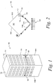
Figure 1 depicts a perspective view of a wind power generation system according to an example. -
Figure 2 depicts a sectional top view of the example wind power generation system ofFigure 1 . -
Figure 3 depicts a sectional side view of the example wind power generation system ofFigure 1 . -
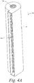
Figure 4A illustrates a perspective view of a centrifugal fan according to an example. -
Figure 4B illustrates a partial view of the example centrifugal fan depicted inFigure 4A . -
Figure 5 depicts a perspective view of an example intake of the wind power generation system. -
Figure 6 depicts a perspective view of an example intake of the wind power generation system. -
Figure 7 depicts a perspective view of an example wind power generation system. -
Figure 8 depicts a flow chart for a method of generating electrical energy from wind according to an example. -
Figure 9 depicts a flow chart for a method of installing a wind power generation system in a structure according to an example. -
Figure 10 depicts a sectional top view of an example wind power generation system. - The disclosed methods and systems provide for generating electrical energy from a wind load on a structure, e.g., a building, a bridge, and/or a tower. Although examples are shown in the Figures and described below in the context of a building, it will be understood that principles of the disclosure can extend to apply in other structures such as, for example, a bridge or a tower.
-
Figures 1-3 depict a windpower generation system 100 according to an example of the disclosure. To more clearly depict aspects of thepower generation system 100,Figures 1-3 are not to scale relative to each other. As shown inFigure 1 , thepower generation system 100 includes abuilding 102 having a plurality of exterior,lateral surfaces 104A-104D and aroof 106. Thebuilding 102 can be, for example, a single-family house, a low-rise building, a mid-rise building, and/or a high-rise building utilized for commercial, industrial, and/or residential purposes. -
Figure 1 further showsexample wind 108 incident on and traversing theexterior surfaces building 102. In general, when thewind 108 encounters theexterior surfaces building 102, thewind 108 is forced along theexterior surfaces respective corners 110 of thebuilding 102. Additionally, due at least in part to air pressure differences at thecorners 110, thewind 108 accelerates as it traverses along theexterior surfaces corners 110. The wind incident on and traversing an exterior surface of a building may also be referred to as a wind load on that exterior surface of the building. - The
power generation system 100 advantageously captures such wind loads on theexterior surface 104A and directs the capturedwind 108 to awind turbine 112 in an interior of thebuilding 102 to generate electrical energy. To capturewind 108 incident on and traversing theexterior surface 104A of thebuilding 102, thepower generation system 100 includes anintake 114 on theexterior surface 104A. As shown inFigure 2 , theintake 114 provides an opening through which thewind 108 can pass from the exterior,lateral surface 104A into an interior space of thebuilding 102. Theintake 114 can have a size and shape that facilitates directing thewind 108 into thebuilding 102 with reduced (or minimal) air flow resistance. Example implementations of theintake 114 are described below with respect toFigures 5-6 . - In the example shown in
Figures 1-2 , thebuilding 102 includes asingle intake 114 on oneexterior surface 104A; however, as will be described below, thebuilding 102 can includemultiple intakes 114 on one or moreexterior surfaces 104A-104D of thebuilding 102 in other examples. Doing so can facilitate thepower generation system 100 capturing greater amounts ofwind 108 and thus generating greater amounts of electrical energy. - As shown in
Figures 2-3 , theintake 114 is coupled to thewind turbine 112 via anair duct 116. Theair duct 116 includes one ormore walls 120 extending between afirst end 116A coupled to theintake 114 and asecond end 116B coupled to thewind turbine 112. The one ormore walls 120 of theair duct 116 substantially or fully enclose an inner space within theair duct 116. As such, theair duct 116 provides a conduit for directing capturedwind 108 from theintake 114 to thewind turbine 112. In examples, theair duct 116 can have a circular, a rectangular, a square, and/or a polygonal cross-sectional shape. - According to aspects of the disclosure, the
air duct 116 compresses and accelerates thewind 108 as it flows from theintake 114 to thewind turbine 112. To do so, theair duct 116 includes one or more tapered sections, which taper inwardly toward an axis "A" of theair duct 116 from theintake 114 to thewind turbine 112. InFigures 2-3 , theair duct 116 tapers continuously along an entire distance of theair duct 116. Tapering theair duct 116 over the entire distance of theair duct 116 can help to reduce the angle of taper needed to achieve a particular extent of wind compression and acceleration, which in turn can help minimize air flow losses. However, in other examples, theair duct 116 can include one or more non-tapered sections in which the cross-sectional dimensions of theair duct 116 remain fixed over at least a portion of theair duct 116. More generally, theair duct 116 can be configured such that cross-sectional dimensions of theair duct 116 are greater at thefirst end 116A than at thesecond end 116B and, in some implementations, greatest at thefirst end 116A and smallest at thesecond end 116B. Theduct 116 thus acts as a fluid mechanics nozzle to compress and accelerate thewind 108. - By compressing and accelerating the
wind 108, the air velocity and thereby flow energy density is increased. This allows for more efficient electrical energy generation by thewind turbine 112 described below. Additionally, compressing and accelerating thewind 108 via theduct 116 can provide for more efficient use of interior space within thebuilding 102. - The
air duct 116 can have a linear taper of varying degrees and shapes for modifying the amount ofwind 108 compression and/or acceleration. In an example, theair duct 116 can have a linear taper of approximately 20 degrees. Theair duct 116 can be continuously tapered using a multi-power polynomial taper shape using a complex computational fluid dynamics (CFD) algorithm. Still other examples are also possible. - In
Figures 2-3 , theair duct 116 is shown as a straight run between theintake 114 and thewind turbine 112. That is, theair duct 116 does not include any elbows or turns. This can beneficially reduce or mitigate air flow resistance within theair duct 116. Optionally, theair duct 116 can include one or more elbows or turns to provide greater flexibility in the relative positioning between theintake 114 and thewind turbine 112 in thebuilding 102. For instance,Figure 10 illustrates an examplepower generation system 1000 including aduct 1016, which turns between anintake 1014 and awind turbine 1012. - As described above, the
wind turbine 112 is coupled to thesecond end 116B of theair duct 116. Thewind turbine 112 converts the kinetic energy of thewind 108 received from theduct 116 into electrical energy. To do so, thewind turbine 112 includes acentrifugal fan 122 coupled to anelectric generator 124. In particular, thewind 108 received in thewind turbine 112 rotates afan blade assembly 132 in thecentrifugal fan 122, which causes theelectric generator 124 to generate electrical energy. For example, thefan blade assembly 132 can be coupled to theelectric generator 124 by ashaft 126 such that rotation of thefan blade assembly 132 rotates theshaft 126, which in turn rotates a rotor within a stator of theelectric generator 124 to generate electric energy. Thefan blade assembly 132 and the rotor can rotate at the same speed (e.g., in a direct-drive configuration). Thewind turbine 112 can also include a gearbox (not shown) to step-up and/or step-down a speed of rotational coupling between thecentrifugal fan 122 and theelectric generator 124. - Utilizing the
centrifugal fan 122 to convert the kinetic energy of thewind 108 to electrical energy provides a number of benefits. For example, the fan blades of acentrifugal fan 122 provide a greater surface area per volume for the wind to act on relative to propeller-type turbines conventionally used for wind power generation. As a result, thewind turbine 112, which has thecentrifugal fan 122, can generate electrical energy at lower wind speeds than similarly sized propeller-type wind turbines. Additionally, for example, acentrifugal fan 122 may be quieter to operate than a propeller-type wind turbine as air turbulence and turbine efficiencies directly relate to fan noise. - According to aspects of the disclosure, the electrical energy generated by the
wind turbine 112 can be provided to an electrical network within thebuilding 102, an electrical power grid external to thebuilding 102, and/or one or more energy storage devices 125 such as, for example, one or more rechargeable batteries, thermal storage devices (e.g., molten salts), flywheels, and/or superconducting magnetic coils. Thus, the generated electrical energy can be used to operate electrical devices within thebuilding 102 and/or stored for later use by such devices. - As shown in
Figure 3 , thewind turbine 112 is further coupled to anexhaust duct 118, which facilitates egress of thewind 108 from thepower generation system 100. As thewind 108 passes through thecentrifugal fan 122, thewind 108 turns 90 degrees and exits thecentrifugal fan 122 via theexhaust duct 118. Theexhaust duct 118 can direct thewind 108 from thecentrifugal fan 122 to anexhaust opening 144 in thebuilding 102. For instance, inFigure 1 , theexhaust opening 144 is on theroof 106; however, theexhaust opening 144 can be in different locations in other examples. - Optionally, the
exhaust duct 118 can be coupled to a heating, ventilating, and air conditioning (HVAC) system in thebuilding 102. In this way, thewind 108 exhausted from thepower generation system 100 can be used to improve air flow in the HVAC system. This may, for example, mitigate the need for booster fans in the HVAC system. - As described above, the
wind turbine 112 includes acentrifugal fan 122.Figure 4A illustrates acentrifugal fan 122 according to one example. Thecentrifugal fan 122 includes afan blade assembly 132 in ahousing 134. Thehousing 134 has an inlet 136 for receivingwind 108 from theair duct 116 and anoutlet 138 for exhausting air to theexhaust duct 118. As shown inFigure 4A , the inlet 136 is generally perpendicular to theoutlet 138. -
Figure 4B depicts thecentrifugal fan 122 ofFigure 4A with a portion of thehousing 134 removed to expose thefan blade assembly 132. As shown inFigure 4B , thefan blade assembly 132 includes a plurality of fan blades 140 coupled to ahub 142. InFigure 4B , each of the fan blades 140 curves against a direction of rotation of the fan blade assembly 132 (i.e., in a "backward-curved" configuration). Alternatively, the fan blades 140 can curve in the direction of rotation of the fan blade assembly 132 (i.e., in a "forward-curved" configuration) or the fan blades 140 can extend from thehub 142 without curving (i.e., in a "straight radial" configuration). Afan blade assembly 132 having a backward-curved configuration can provide for greater efficiency than a forward-curved configuration or a straight radial configuration in some implementations. - As described above, when
wind 108 enters the inlet 136 from theair duct 116, thewind 108 acts on the fan blades 140 of thefan blade assembly 132. In particular, thewind 108 causes thefan blade assembly 132 to rotate within thehousing 134. The rotational energy of thefan blade assembly 132 is transferred to the generator 124 (e.g., via the shaft 126), which converts the rotational energy into electrical energy. Rotation of the fan blades 140 further applies a centrifugal force to thewind 108, which forces thewind 108 out of thehousing 134 via theoutlet 138. - In the illustrated example, the
outlet 138 is coaxial with an axis of rotation of thefan blade assembly 132 and the inlet 136 is perpendicular to that axis of rotation. However, thewind 108 can be received via theoutlet 138 shown inFigure 4A and exhausted via the inlet 136. That is, thewind 108 can be received from theair duct 116 through an opening parallel to the axis of rotation of thefan blade assembly 132 and exhaust thewind 108 perpendicular to the axis of rotation of thefan blade assembly 132. - The
centrifugal fan 122 can also optionally include a brake system to facilitate safe maintenance, repair, and/or upgrading of thepower generation system 100. The brake system can have a first state of operation in which the brake system is disengaged from thefan blade assembly 132 to allow rotation of thefan blade assembly 132, and a second state of operation in which the brake system is engaged with thefan blade assembly 132 to stop or prevent rotation of thefan blade assembly 132. In this way, the brake system can be selectively actuated between the first and second states to facilitate safe repair and/or maintain thepower generation system 100. - As described above, the
intake 114 captures wind incident on and traversing theexterior surface 104A of thebuilding 102.Figures 5-6 depict example configurations for theintake 114, which can be utilized in the power generation systems described herein (e.g., the power generation system 100).Figure 5 depicts anexample intake 514 on theexterior surface 104A of thebuilding 102. As shown inFigure 5 , theintake 514 is formed as a recessed opening in theexterior surface 104A. In particular, theintake 514 has an inwardly slopingsurface 528, which forms the recessed opening in theexterior surface 104A. As further shown inFigure 5 , when thewind 108 traversing theexterior surface 104A encounters theintake 514, thewind 108 flows through a gap between thesurface 528 and thesurface 104A to then pass into theduct 116. - In
Figure 5 , theintake 514 is flush with theexterior surface 104A as no portion of theintake 514 protrudes outwardly from theexterior surface 104A. By having a recessedintake 514, theintake 514 may have little or no negative impact on the aesthetics of thebuilding 102. This may help to reduce or eliminate a significant barrier to deploying wind power generation systems in buildings and urban environments. - As shown in
Figure 6 , theintake 614 includes ascoop 630 that protrudes from theexterior surface 104A to facilitate capturing greater amounts of wind compared to a recessed-type intake 514. While a scoop-type intake 614 may improve wind capture functionality, the protruding scoop may be more noticeable to observers than a recessed-type intake 514. Yet, relative to the substantial space and size requirements of conventional propeller-type wind turbines, the scoop 130 is relatively small and less likely to impact building aesthetics. - Optionally, the
intake 114 can include aspects of both the recessed-type intake 514 and the scoop-type intake 614. For example, theintake 114 can include both an inwardly sloping surface (e.g., the surface 528) and a scoop (e.g., the scoop 630). - According to some aspects, the
system 100 can also include an intake filter (not shown) that is configured to inhibit solid objects (such as, for example, birds, bats, insects, plastic bags, and garbage) from entering theintake - In the illustrated examples, the
intakes building 102. However, theintakes intakes intakes intakes - In
Figure 1 , theintake 114 is located at acorner 110 of thebuilding 102. Locating theintake 114 at acorner 110 of thebuilding 102 can advantageously facilitate capturing greater wind loads in theintake 114 relative to other locations on the exterior surface 104 (e.g., due towind 108 accumulating and traversing over a greater surface area of the exterior surface 104); however, theintake 114 can be in different locations on the exterior surface 104 as shown inFigure 7 . Additionally, although thebuilding 102 includes only oneintake 114,duct 116, andwind turbine 112 inFigures 1-3 , thebuilding 102 can include more than oneintake 114,duct 116, and/orwind turbine 112. Integratingmultiple intakes 114,ducts 116, andwind turbines 112 into thebuilding 102 can provide for capture of greater wind loads on thebuilding 102 and, thus, greater electrical energy generation. - As noted above, the wind
power generation system 100 can include any number ofintakes 114,ducts 116, andwind turbines 112 in any location on any surface of thebuilding 102. As an example of this,Figure 7 depicts apower generation system 700 in which abuilding 702 includesmultiple intakes 714 at various locations onexterior surfaces 704 of thebuilding 702. Also, inFigure 7 , one of theintakes 714 is located on aroof 706 of thebuilding 702. As shown inFigure 7 , the size and orientation of at least someintakes 714 differs relative to other ones of theintakes 714. Also, as shown inFigure 7 , intakes 714' are located and oriented so as to capture an updraft and a downdraft, respectively, on one of the exterior surfaces 704. The number, location, size, and orientation of theintakes 714, 714' can be based on factors such as, for example, expected wind loads, space constraints within thebuilding 702 interior, and/or electrical energy generation needs of thebuilding 702. Although not shown, thesystem 700 can further include multiple ducts, wind turbines, and exhaust ducts each coupled to a respective one of theintakes 714 in a manner similar to that described above. - As illustrated and described above, each wind turbine receives wind from a single duct and a single intake; however, according to additional or alternative examples, a single wind turbine can receive wind from multiple ducts and/or multiple intakes. In such examples, the system can include one or more features configured to facilitate mixing of the wind received the different ducts and/or intakes so as to mitigate resistance and/or other loses. For example, the system can include one or more directional slats in the air duct, which help to reduce turbulence of air flow between the multiple air streams. By directing wind from multiple intakes and/or ducts to a common wind turbine, even greater amounts of wind can be captured and directed to the wind turbine. This may help to achieve more efficient utilization of space within the building for power generation.
- As described above, the power generation systems of the present disclosure are generally located in an interior space of the
building 102. This provides a number of additional benefits and advantages over conventional propeller-type systems. For example, because the wind turbine(s) are located in an interior space of thebuilding 102, the power generation systems of this disclosure address environmental impacts associated with conventional propeller-type wind turbines (e.g., wildlife colliding with propellers). Additionally, by locating the components of the power generation systems in an interior space of thebuilding 102, the systems can be easily, safely, and cost-efficiently repaired, serviced, and/or upgraded from that interior space of thebuilding 102. By contrast, conventional windmills are required to be placed in open spaces exposed to potentially harsh and/or hazardous environmental conditions. Further still, locating the components of the power generation systems in thebuilding 102 helps to maintain building aesthetics. - Referring now to
Figure 8 , a flow chart for an example method of generating electrical energy from wind is depicted. Atblock 860, an intake captures wind on an exterior, lateral surface of a building. Atblock 862, a duct directs the captured wind from the intake to a centrifugal fan. Atblock 864, while directing the wind from the intake to the centrifugal fan, the duct compresses and accelerates the wind. Atblock 866, after the wind has been compressed and accelerated in the duct, the centrifugal fan receives the wind from the duct. Atblock 868, the wind rotates a fan blade assembly in the centrifugal fan. Atblock 870, responsive to the rotation of the fan blade assembly, electrical energy is generated. - The flow chart illustrated in
Figure 8 is one example of a method for generating electrical energy from wind. The method of electrical energy generation can omit steps, include additional steps, and/or modify the order of steps presented above. - Referring now to
Figure 9 , a flow chart for an example method of installing a wind power generation system in a building is depicted. In some implementations, the method may be carried out to retrofit an existing building with the wind power generation system. Alternatively, the method may be carried out concurrent with construction of the building. - At
block 980, the method involves forming an intake in an exterior, lateral surface of the building. The intake can be formed, for example, by forming an opening in the exterior, lateral surface of the building. The opening can be sloped downwardly from the exterior, lateral surface of the building so as to provide a recessed intake. Optionally, forming the intake can include coupling a scoop to the exterior surface at the opening. - At
block 982, a wind turbine is installed in an interior space of the building (e.g., a maintenance room). Atblock 984, a first end of the duct is coupled to the intake. Atblock 986, a second of the duct is coupled to the wind turbine. In particular, the second of the duct can be coupled to an inlet of a centrifugal fan in the wind turbine. Atblock 988, an outlet of the wind turbine is coupled to an exhaust duct configured to facilitate egress of the wind from the interior space in the building. Atblock 990, a generator of the wind turbine is electrically coupled to an electrical network of the building, an electric power grid external to the building, and/or an energy storage device. - The flow chart illustrated in
Figure 9 is one example of a method for installing a wind power generation system in a building. The method of installation can omit steps, include additional steps, and/or modify the order of steps presented above. - Further, the disclosure comprises embodiments according to the following embodiments. Features of each of these embodiments can be combined with one or more other embodiments from elsewhere in this disclosure, in any suitable manner.
- In one embodiment, there is provided a method for generating electrical energy from wind, comprising: capturing wind in an intake on an exterior surface of a structure; directing, via a duct, the wind from the intake to a centrifugal fan; while directing the wind from the intake to the centrifugal fan, compressing and accelerating the wind in the duct; receiving, in the centrifugal fan, the wind from the duct; rotating, via the received wind, a fan blade assembly in the centrifugal fan; and generating electrical energy, via a generator, based on the rotation of the fan blade assembly.
- Optionally, the centrifugal fan is located in an interior space of the structure.
- Optionally, capturing the wind in the intake comprises receiving the wind into a recessed opening in the exterior surface of the structure, and the intake is flush with the exterior surface.
- Optionally, capturing the wind in the intake comprises capturing the wind in a scoop protruding from the exterior surface.
- Optionally, the exterior surface is a lateral surface of the structure.
- Optionally, the duct tapers inwardly in a direction from the intake to the centrifugal fan to compress and accelerate the wind.
- Optionally, the duct tapers continuously along an entire distance of the duct from the intake to the centrifugal fan.
- Optionally, the method further comprises exhausting the wind from the centrifugal fan in a direction that is perpendicular to a direction in which the wind is received in the centrifugal fan.
- Optionally, the method further comprises directing the wind exhausted from the centrifugal fan into a heating, ventilating, and air conditioning (HVAC) system to assist air flow in the HVAC system.
- Optionally, the method further comprises storing, via an energy storage device, the generated electrical energy.
- In one embodiment, there is provided a system for generating electrical energy from a wind load on a structure, comprising: an intake, on an exterior surface of a structure, configured to capture wind on the exterior surface; a duct coupled to the intake at a first end of the duct and configured to direct the wind from the first end to a second end of the duct, wherein the duct is configured to compress and accelerate the wind directed from the first end to the second end; a centrifugal fan coupled to the second end of the duct for receiving the wind from the duct, the centrifugal fan including a fan blade assembly configured to rotate responsive to the wind received from the duct; and a generator configured to generate electrical energy based on the rotation of the fan blade assembly.
- Optionally, the system further comprises an energy storage device configured to store the electrical energy generated by generator.
- Optionally, the duct tapers inwardly in a direction from the first end to the second end to compress and accelerate the wind.
- Optionally, the duct tapers continuously along an entire distance of the duct from the intake to the centrifugal fan.
- Optionally, the intake is flush with the exterior surface of the structure.
- Optionally, the intake further comprises a scoop protruding from the exterior surface.
- Optionally, the fan blade assembly comprises a plurality of fan blades, and each of the plurality of fan blades curves against a direction of rotation of the fan blade assembly.
- Optionally, the system further comprises an exhaust duct coupled to an outlet of the centrifugal fan and is configured to exhaust wind from the centrifugal fan, wherein the second end of the duct is coupled to an inlet of the centrifugal fan, and wherein the inlet is perpendicular to the outlet.
- Optionally, the outlet is coaxial with an axis of rotation of the fan blade assembly.
- Optionally, the exterior surface is a lateral surface of the structure.
- Optionally, the intake is located at a corner of the structure.
- Optionally, the intake comprises a plurality of intakes and the exterior surface comprises a plurality of exterior surfaces such that the wind is captured at a plurality of locations on the structure.
- Example aspects have been described above. After studying the configurations, examples, and arrangements described herein a skilled person may come to understand, however, that changes and modifications may be made without departing from the true scope of the disclosure. The description of the different advantageous aspects has been presented for purposes of illustration and description, and is not intended to be exhaustive or limited to the form disclosed. After reviewing this disclosure, many modifications and variations will become apparent to those of ordinary skill in the art. Further, different advantageous aspects may provide different advantages as compared to other advantageous aspects. The example aspects selected are chosen and described in order to best explain the principles of the disclosure, the practical application, and to enable others of ordinary skill in the art to understand the disclosure with various modifications as are suited to the particular use contemplated.
Claims (15)
- A method for generating electrical energy from wind, comprising:capturing wind in an intake (114, 614) on an exterior surface (104A) of a structure;directing, via a duct (116), the wind (108) from the intake to a centrifugal fan (122);while directing the wind from the intake (114) to the centrifugal fan (122), compressing and accelerating the wind in the duct (116);receiving, in the centrifugal fan (122), the wind (108) from the duct (116);rotating, via the received wind (108), a fan blade assembly (132) in the centrifugal fan (122); andgenerating electrical energy, via a generator (124), based on the rotation of the fan blade assembly (132).
- The method of claim 1, wherein the centrifugal fan (122) is located in an interior space of the structure.
- The method of claim 1 or 2, wherein capturing the wind (108) in the intake (114, 614) comprises receiving the wind into a recessed opening in the exterior surface (104A) of the structure, and wherein the intake (114, 614) is flush with the exterior surface (104A), or
wherein capturing the wind ((108) in the intake (114, 614) comprises capturing the wind (108) in a scoop (630) protruding from the exterior surface (104A). - The method of any one of claims 1-3, wherein the exterior surface is a lateral surface of the structure.
- The method of any one of claims 1-4, wherein the duct tapers inwardly in a direction from the intake to the centrifugal fan (122) to compress and accelerate the wind (108), and wherein the duct optionally tapers continuously along an entire distance of the duct (116) from the intake to the centrifugal fan (122).
- The method of any one of claims 1-5, further comprising exhausting the wind (108) from the centrifugal fan (122) in a direction that is perpendicular to a direction in which the wind (108) is received in the centrifugal fan (122), optionally the method further comprising directing the wind (108) exhausted from the centrifugal fan (122) into a heating, ventilating, and air conditioning (HVAC) system to assist air flow in the HVAC system.
- The method of any one of claims 1-6, further comprising storing, via an energy storage device (125), the generated electrical energy.
- A system for generating electrical energy from a wind load on a structure, comprising:an intake (114, 614), on an exterior surface (104A) of a structure, configured to capture wind on the exterior surface;a duct (116) coupled to the intake at a first end of the duct and configured to direct the wind from the first end (116A) to a second end (116B) of the duct (116), wherein the duct is configured to compress and accelerate the wind (108) directed from the first end (116A) to the second end (116B);a centrifugal fan (122) coupled to the second end of the duct (116B) for receiving the wind from the duct, the centrifugal fan (122) including a fan blade assembly (132) configured to rotate responsive to the wind (108) received from the duct (116); anda generator (124) configured to generate electrical energy based on the rotation of the fan blade assembly (132).
- The system of claim 8, further comprising an energy storage device (125) configured to store the electrical energy generated by generator (124).
- The system of claim 8 or 9, wherein the duct (116) tapers inwardly in a direction from the first end (116A) to the second end (116B) to compress and accelerate the wind, wherein the duct (116) optionally tapers continuously along an entire distance of the duct from the intake to the centrifugal fan (122).
- The system of any one of claims 8-10, wherein the intake (114, 614) is flush with the exterior surface (104A) of the structure, and/or wherein the exterior surface (104A) is a lateral surface of the structure (102), and/or wherein the intake (114, 614) further comprises a scoop (630) protruding from the exterior surface (104A).
- The system of any one of claims 8-13, wherein the fan blade assembly (132) comprises a plurality of fan blades, and each of the plurality of fan blades curves against a direction of rotation of the fan blade assembly.
- The system of any one of claims 8-12, further comprising an exhaust duct (118) coupled to an outlet (138) of the centrifugal fan (122) and configured to exhaust wind from the centrifugal fan, wherein the second end of the duct (116B) is coupled to an inlet (136) of the centrifugal fan (122), wherein the inlet is perpendicular to the outlet (138) wherein the outlet (138) is optionally coaxial with an axis of rotation of the fan blade assembly (132).
- The system of any one of claims 8-13, wherein the intake (114, 614) is located at a corner of the structure (102).
- The system of any one of claims 8-14, wherein the intake (114, 614) comprises a plurality of intakes (114, 614) and the exterior surface (104A) comprises a plurality of exterior surfaces such that the wind is captured at a plurality of locations on the structure (102).
Applications Claiming Priority (1)
| Application Number | Priority Date | Filing Date | Title |
|---|---|---|---|
| US15/047,324 US10443570B2 (en) | 2016-02-18 | 2016-02-18 | Internal mounted cylindrical turbine for electricity generation using exterior flush and scoop intakes |
Publications (2)
| Publication Number | Publication Date |
|---|---|
| EP3208461A1 true EP3208461A1 (en) | 2017-08-23 |
| EP3208461B1 EP3208461B1 (en) | 2019-08-21 |
Family
ID=58054051
Family Applications (1)
| Application Number | Title | Priority Date | Filing Date |
|---|---|---|---|
| EP17156458.6A Active EP3208461B1 (en) | 2016-02-18 | 2017-02-16 | Internal mounted cylindrical turbine for electricity generation using exterior flush and scoop intakes |
Country Status (5)
| Country | Link |
|---|---|
| US (2) | US10443570B2 (en) |
| EP (1) | EP3208461B1 (en) |
| CN (1) | CN107091204B (en) |
| BR (1) | BR102017003156B1 (en) |
| CA (2) | CA2954987C (en) |
Cited By (1)
| Publication number | Priority date | Publication date | Assignee | Title |
|---|---|---|---|---|
| GB2612664A (en) * | 2021-06-22 | 2023-05-10 | Robert Doe William | Wind-powered electricity generator |
Families Citing this family (3)
| Publication number | Priority date | Publication date | Assignee | Title |
|---|---|---|---|---|
| US10443570B2 (en) | 2016-02-18 | 2019-10-15 | The Boeing Company | Internal mounted cylindrical turbine for electricity generation using exterior flush and scoop intakes |
| DE102020000063B4 (en) * | 2020-01-08 | 2022-02-24 | Viktor Rakoczi | Scalable wind power plant |
| WO2022187911A1 (en) * | 2021-03-11 | 2022-09-15 | Christopher Neill Martin | Wind powered generator |
Citations (5)
| Publication number | Priority date | Publication date | Assignee | Title |
|---|---|---|---|---|
| DE102007013885A1 (en) * | 2006-03-20 | 2007-09-27 | Boecker-Kamradt, Sylvia | Installation for generating electrical energy from wind energy, has wind wheel designed as radial rotor, and rotor blades have form of airplane wings |
| DE102008038895A1 (en) * | 2008-08-13 | 2010-02-25 | Joachim Fehr | Wind-power plant for building, is arranged under roof or as roof, and air guides are aligned by guiding plates with flaps, which are fitted in fixed or movable manner |
| US20100247302A1 (en) * | 2009-06-19 | 2010-09-30 | University Of Miami | Wind energy system |
| JP2011174447A (en) * | 2010-02-25 | 2011-09-08 | Taisei Corp | Power generation system for super-high rise building |
| US20120080884A1 (en) * | 2010-09-29 | 2012-04-05 | Mr. Francois Gagnon | Corner wind turbine for tall building |
Family Cites Families (56)
| Publication number | Priority date | Publication date | Assignee | Title |
|---|---|---|---|---|
| US4070131A (en) * | 1975-01-20 | 1978-01-24 | Grumman Aerospace Corporation | Tornado-type wind turbine |
| US4144802A (en) * | 1977-01-19 | 1979-03-20 | Babin Paul A | Hurricane/tornado building protection system |
| US4122675A (en) * | 1977-03-17 | 1978-10-31 | Jack Polyak | Solar heat supplemented convection air stack with turbine blades |
| US4321476A (en) * | 1980-06-24 | 1982-03-23 | Buels Jesse H | Bi-directional wind power generator |
| ES8301330A1 (en) * | 1980-07-24 | 1982-12-01 | Central Energetic Ciclonic | System for the obtaining of energy by fluid flows resembling a natural cyclone or anti-cyclone |
| US5284628A (en) * | 1992-09-09 | 1994-02-08 | The United States Of America As Represented By The United States Department Of Energy | Convection towers |
| US5394016A (en) * | 1993-04-22 | 1995-02-28 | Hickey; John J. | Solar and wind energy generating system for a high rise building |
| US6097104A (en) * | 1999-01-19 | 2000-08-01 | Russell; Thomas H. | Hybrid energy recovery system |
| US20110095538A1 (en) * | 2009-10-28 | 2011-04-28 | Joseph Akwo Tabe | Wind and hydropower plant |
| CN2382851Y (en) * | 1999-06-22 | 2000-06-14 | 王晓平 | Wind force electric generator |
| US6765309B2 (en) * | 2001-12-19 | 2004-07-20 | Joseph J. Tallal, Jr. | System and building for generating electricity using wind power |
| ITPC20040016A1 (en) * | 2004-04-19 | 2004-07-19 | Angelo Comandu | PLANT FOR THE PRODUCTION OF WIND ENERGY AND RELATED PROCEDURE. |
| US7163156B2 (en) * | 2004-10-06 | 2007-01-16 | Lawrence Kates | System and method for zone heating and cooling |
| US7215037B2 (en) * | 2004-11-19 | 2007-05-08 | Saverio Scalzi | Protective wind energy conversion chamber |
| US9453494B2 (en) * | 2005-12-29 | 2016-09-27 | Brett C Krippene | Building integrated wind energy power enhancer system |
| US20100001532A1 (en) * | 2006-06-12 | 2010-01-07 | Mihai Grumazescu | Wind-driven turbine cells and arrays |
| CN101105081A (en) * | 2006-07-11 | 2008-01-16 | 程新生 | Wind energy edifice |
| WO2008075422A1 (en) * | 2006-12-20 | 2008-06-26 | Hashimoto, Yoshimasa | Wind-driven generator |
| US20080179053A1 (en) * | 2007-01-29 | 2008-07-31 | Lawrence Kates | System and method for zone thermostat budgeting |
| US20080188174A1 (en) * | 2007-02-01 | 2008-08-07 | Rouzbeh Aminpour | Power system for a building structure |
| US8362635B2 (en) * | 2007-03-31 | 2013-01-29 | Mdl Enterprises, Llc | Wind-driven electric power generation system adapted for mounting along the side of vertical, man-made structures such as large buildings |
| US7911075B2 (en) * | 2007-10-15 | 2011-03-22 | Pagliasotti Robert R | Building-integrated system for capturing and harvesting the energy from environmental wind |
| US20100060010A1 (en) * | 2008-09-10 | 2010-03-11 | Iosif Gaportsin | Ecology friendly compound energy unit |
| US8421265B2 (en) | 2009-02-09 | 2013-04-16 | Grayhawke Applied Technologies | System and method for generating electricity within a building structure |
| US7811048B2 (en) | 2009-02-12 | 2010-10-12 | Quality Research, Development & Consulting, Inc. | Turbine-intake tower for wind energy conversion systems |
| US20100237627A1 (en) * | 2009-03-20 | 2010-09-23 | Bert Socolove | Vehicle mounted wind powered hydrogen generator |
| BRPI1012576A2 (en) * | 2009-06-01 | 2019-09-24 | Lei Shengqing | compressed air wind turbine generator system that has a substantially square movable body |
| US20110021134A1 (en) * | 2009-07-23 | 2011-01-27 | Arthur Louis Zwern | Multi-function ventilation and electrical system |
| US20110021133A1 (en) * | 2009-07-23 | 2011-01-27 | Arthur Louis Zwern | Passive heating, cooling, and ventilation system |
| US20110133468A1 (en) * | 2009-12-04 | 2011-06-09 | John Leith | Wind powered generating system |
| US9032679B2 (en) * | 2010-01-20 | 2015-05-19 | Propst Family Limited Partnership | Roof panel and method of forming a roof |
| US20140150362A1 (en) * | 2010-01-20 | 2014-06-05 | Propst Family Limited Partnership | Building panels and method of forming building panels |
| CN101737270B (en) * | 2010-02-05 | 2011-09-07 | 济南高新开发区中泰环保技术开发中心 | Extra-large-size vertical-shaft wind power generation device |
| CN102146711A (en) * | 2010-02-10 | 2011-08-10 | 西安孔明电子科技有限公司 | Wind power generation building wallboard and construction method |
| US20110291421A1 (en) * | 2010-06-01 | 2011-12-01 | Fang Ming Tsung | Wind-Deflection Omni-Directional Vertical Wind-Driven Device |
| US8672608B2 (en) * | 2010-11-15 | 2014-03-18 | Chuy-Nan Chio | Tower type vertical axle windmill |
| EP2487362A1 (en) * | 2011-02-11 | 2012-08-15 | E-Mills ApS | Underground watermill |
| US10670028B2 (en) * | 2011-10-21 | 2020-06-02 | Prime Datum Development Company, Llc | Load bearing direct drive fan system with variable process control |
| KR200460486Y1 (en) * | 2011-12-01 | 2012-05-23 | 손호윤 | Pillar type wind electric power generator |
| US9294013B2 (en) | 2012-09-06 | 2016-03-22 | Sheer Wind, Inc. | Buildings with wind-energy-conversion systems |
| US9121389B2 (en) * | 2012-09-24 | 2015-09-01 | Jess Edward Baker | Energy producing building structures |
| US20140369826A1 (en) * | 2012-10-05 | 2014-12-18 | Steven Rohring | Tornado wind energy conversion system wind turbine |
| US20140265335A1 (en) * | 2013-03-15 | 2014-09-18 | Bruno Peter Andreis | Ultra high efficiency power generation system and water turbine |
| AU2015202537B2 (en) * | 2013-04-05 | 2017-08-17 | Siang Teik Teoh | Coaxial ventilator |
| US9145868B2 (en) * | 2013-09-25 | 2015-09-29 | Air Era Technologies, LLC | Vertical axis turbine and constructions employing same |
| US9358491B2 (en) * | 2014-01-30 | 2016-06-07 | Farouk Dakhil | Carbon dioxide neutralizing power generating device |
| US20140284928A1 (en) * | 2014-04-22 | 2014-09-25 | Research Energy Llc. | Harnessing electricity from controlled tornado |
| US9951752B2 (en) * | 2014-05-29 | 2018-04-24 | The Florida International University Board Of Trustees | Active aerodynamics mitigation and power production system for buildings and other structures |
| US20160047360A1 (en) * | 2014-08-12 | 2016-02-18 | James Patrick Fex, JR. | Method and apparatus to utilize the push-pull power of an upwards flow of wind energy within a structure |
| US20170250626A1 (en) * | 2014-09-29 | 2017-08-31 | Stargreen Power Corporation | Energy System with C02 Extraction |
| US20160281679A1 (en) * | 2015-01-29 | 2016-09-29 | Donald Wichers | Fluid driven electric power generation system |
| US9371818B1 (en) * | 2015-08-10 | 2016-06-21 | Mark T. Monto | Cyclonic aeolian vortex turbine |
| US10823140B2 (en) * | 2015-11-06 | 2020-11-03 | Linton K. Samarasinha | Vertical axis wind turbine structure |
| US10443570B2 (en) | 2016-02-18 | 2019-10-15 | The Boeing Company | Internal mounted cylindrical turbine for electricity generation using exterior flush and scoop intakes |
| AR103820A1 (en) * | 2016-03-01 | 2017-06-07 | Klarenberg Alejandro José | CONSTRUCTION DEFINING A SUBMERGED VOLUME IN AN AIR CURRENT, ABLE TO ADDRESS AND ACCELERATE THIS AIR CURRENT TO AT LEAST A WIND GENERATOR ASSOCIATED WITH SUCH CONSTRUCTION |
| US20200149260A1 (en) * | 2018-11-08 | 2020-05-14 | Ganapathi Pamula | Power generation devices and methods for use with toilets |
-
2016
- 2016-02-18 US US15/047,324 patent/US10443570B2/en active Active
-
2017
- 2017-01-13 CA CA2954987A patent/CA2954987C/en active Active
- 2017-01-13 CA CA3111504A patent/CA3111504C/en active Active
- 2017-02-16 BR BR102017003156-0A patent/BR102017003156B1/en not_active IP Right Cessation
- 2017-02-16 EP EP17156458.6A patent/EP3208461B1/en active Active
- 2017-02-17 CN CN201710085003.3A patent/CN107091204B/en not_active Expired - Fee Related
-
2019
- 2019-09-04 US US16/559,904 patent/US10865776B2/en not_active Expired - Fee Related
Patent Citations (5)
| Publication number | Priority date | Publication date | Assignee | Title |
|---|---|---|---|---|
| DE102007013885A1 (en) * | 2006-03-20 | 2007-09-27 | Boecker-Kamradt, Sylvia | Installation for generating electrical energy from wind energy, has wind wheel designed as radial rotor, and rotor blades have form of airplane wings |
| DE102008038895A1 (en) * | 2008-08-13 | 2010-02-25 | Joachim Fehr | Wind-power plant for building, is arranged under roof or as roof, and air guides are aligned by guiding plates with flaps, which are fitted in fixed or movable manner |
| US20100247302A1 (en) * | 2009-06-19 | 2010-09-30 | University Of Miami | Wind energy system |
| JP2011174447A (en) * | 2010-02-25 | 2011-09-08 | Taisei Corp | Power generation system for super-high rise building |
| US20120080884A1 (en) * | 2010-09-29 | 2012-04-05 | Mr. Francois Gagnon | Corner wind turbine for tall building |
Cited By (1)
| Publication number | Priority date | Publication date | Assignee | Title |
|---|---|---|---|---|
| GB2612664A (en) * | 2021-06-22 | 2023-05-10 | Robert Doe William | Wind-powered electricity generator |
Also Published As
| Publication number | Publication date |
|---|---|
| US20170241406A1 (en) | 2017-08-24 |
| US10865776B2 (en) | 2020-12-15 |
| US20190390653A1 (en) | 2019-12-26 |
| CN107091204A (en) | 2017-08-25 |
| CA2954987C (en) | 2021-05-04 |
| US10443570B2 (en) | 2019-10-15 |
| CN107091204B (en) | 2021-06-01 |
| CA3111504A1 (en) | 2017-08-18 |
| EP3208461B1 (en) | 2019-08-21 |
| CA2954987A1 (en) | 2017-08-18 |
| BR102017003156A2 (en) | 2017-08-22 |
| CA3111504C (en) | 2023-05-02 |
| BR102017003156B1 (en) | 2022-12-13 |
Similar Documents
| Publication | Publication Date | Title |
|---|---|---|
| US10865776B2 (en) | Internal mounted cylindrical turbine for electricity generation using exterior flush and scoop intakes | |
| AU2013313164B2 (en) | Buildings with wind-energy-conversion systems | |
| US8330290B2 (en) | Converting wind energy to electrical energy | |
| US8314508B2 (en) | Method and apparatus for wind energy system | |
| US8362637B2 (en) | Method and apparatus for wind energy system | |
| US20110266802A1 (en) | Tunnel power turbine system to generate potential energy from waste kinetic energy | |
| US8063502B1 (en) | Shrouded wind turbine with dual coaxial airflow passageways | |
| US20190242359A1 (en) | Wind-tunnel turbine vacuum air flow generator | |
| US20140369826A1 (en) | Tornado wind energy conversion system wind turbine | |
| US11655798B2 (en) | Multistage vertical axis wind turbine | |
| US11499526B2 (en) | Apparatus for wind power generation | |
| CN114667391A (en) | Wind turbine and wind power plant based thereon | |
| CN101691853B (en) | Horizontal shaft wind driven generator | |
| KR20140123324A (en) | Ventilation Duct Exhaust Energy Capturing Power Generation System | |
| CN101061312A (en) | Apparatus for generating wind energy for the generation of electrical energy by means of windmills with substantially parallel shafts and a wind compression system while simultaneously generating photovoltaic energy | |
| US20160377054A1 (en) | Stackable Compression & Venturi Diverter Vane | |
| PL226274B1 (en) | Household wind power station |
Legal Events
| Date | Code | Title | Description |
|---|---|---|---|
| PUAI | Public reference made under article 153(3) epc to a published international application that has entered the european phase |
Free format text: ORIGINAL CODE: 0009012 |
|
| STAA | Information on the status of an ep patent application or granted ep patent |
Free format text: STATUS: REQUEST FOR EXAMINATION WAS MADE |
|
| 17P | Request for examination filed |
Effective date: 20170216 |
|
| AK | Designated contracting states |
Kind code of ref document: A1 Designated state(s): AL AT BE BG CH CY CZ DE DK EE ES FI FR GB GR HR HU IE IS IT LI LT LU LV MC MK MT NL NO PL PT RO RS SE SI SK SM TR |
|
| AX | Request for extension of the european patent |
Extension state: BA ME |
|
| GRAP | Despatch of communication of intention to grant a patent |
Free format text: ORIGINAL CODE: EPIDOSNIGR1 |
|
| STAA | Information on the status of an ep patent application or granted ep patent |
Free format text: STATUS: GRANT OF PATENT IS INTENDED |
|
| RIC1 | Information provided on ipc code assigned before grant |
Ipc: F03D 13/20 20160101ALI20181217BHEP Ipc: F03D 9/34 20160101ALI20181217BHEP Ipc: F03D 9/11 20160101AFI20181217BHEP Ipc: F03D 9/25 20160101ALI20181217BHEP Ipc: F03D 9/45 20160101ALI20181217BHEP |
|
| INTG | Intention to grant announced |
Effective date: 20190117 |
|
| GRAJ | Information related to disapproval of communication of intention to grant by the applicant or resumption of examination proceedings by the epo deleted |
Free format text: ORIGINAL CODE: EPIDOSDIGR1 |
|
| STAA | Information on the status of an ep patent application or granted ep patent |
Free format text: STATUS: REQUEST FOR EXAMINATION WAS MADE |
|
| GRAP | Despatch of communication of intention to grant a patent |
Free format text: ORIGINAL CODE: EPIDOSNIGR1 |
|
| STAA | Information on the status of an ep patent application or granted ep patent |
Free format text: STATUS: GRANT OF PATENT IS INTENDED |
|
| INTG | Intention to grant announced |
Effective date: 20190405 |
|
| GRAS | Grant fee paid |
Free format text: ORIGINAL CODE: EPIDOSNIGR3 |
|
| GRAA | (expected) grant |
Free format text: ORIGINAL CODE: 0009210 |
|
| STAA | Information on the status of an ep patent application or granted ep patent |
Free format text: STATUS: THE PATENT HAS BEEN GRANTED |
|
| AK | Designated contracting states |
Kind code of ref document: B1 Designated state(s): AL AT BE BG CH CY CZ DE DK EE ES FI FR GB GR HR HU IE IS IT LI LT LU LV MC MK MT NL NO PL PT RO RS SE SI SK SM TR |
|
| REG | Reference to a national code |
Ref country code: GB Ref legal event code: FG4D |
|
| REG | Reference to a national code |
Ref country code: CH Ref legal event code: EP |
|
| REG | Reference to a national code |
Ref country code: DE Ref legal event code: R096 Ref document number: 602017006224 Country of ref document: DE |
|
| REG | Reference to a national code |
Ref country code: AT Ref legal event code: REF Ref document number: 1170055 Country of ref document: AT Kind code of ref document: T Effective date: 20190915 |
|
| REG | Reference to a national code |
Ref country code: IE Ref legal event code: FG4D |
|
| REG | Reference to a national code |
Ref country code: LT Ref legal event code: MG4D |
|
| REG | Reference to a national code |
Ref country code: NL Ref legal event code: MP Effective date: 20190821 |
|
| PG25 | Lapsed in a contracting state [announced via postgrant information from national office to epo] |
Ref country code: LT Free format text: LAPSE BECAUSE OF FAILURE TO SUBMIT A TRANSLATION OF THE DESCRIPTION OR TO PAY THE FEE WITHIN THE PRESCRIBED TIME-LIMIT Effective date: 20190821 Ref country code: HR Free format text: LAPSE BECAUSE OF FAILURE TO SUBMIT A TRANSLATION OF THE DESCRIPTION OR TO PAY THE FEE WITHIN THE PRESCRIBED TIME-LIMIT Effective date: 20190821 Ref country code: NL Free format text: LAPSE BECAUSE OF FAILURE TO SUBMIT A TRANSLATION OF THE DESCRIPTION OR TO PAY THE FEE WITHIN THE PRESCRIBED TIME-LIMIT Effective date: 20190821 Ref country code: BG Free format text: LAPSE BECAUSE OF FAILURE TO SUBMIT A TRANSLATION OF THE DESCRIPTION OR TO PAY THE FEE WITHIN THE PRESCRIBED TIME-LIMIT Effective date: 20191121 Ref country code: SE Free format text: LAPSE BECAUSE OF FAILURE TO SUBMIT A TRANSLATION OF THE DESCRIPTION OR TO PAY THE FEE WITHIN THE PRESCRIBED TIME-LIMIT Effective date: 20190821 Ref country code: NO Free format text: LAPSE BECAUSE OF FAILURE TO SUBMIT A TRANSLATION OF THE DESCRIPTION OR TO PAY THE FEE WITHIN THE PRESCRIBED TIME-LIMIT Effective date: 20191121 Ref country code: FI Free format text: LAPSE BECAUSE OF FAILURE TO SUBMIT A TRANSLATION OF THE DESCRIPTION OR TO PAY THE FEE WITHIN THE PRESCRIBED TIME-LIMIT Effective date: 20190821 Ref country code: PT Free format text: LAPSE BECAUSE OF FAILURE TO SUBMIT A TRANSLATION OF THE DESCRIPTION OR TO PAY THE FEE WITHIN THE PRESCRIBED TIME-LIMIT Effective date: 20191223 |
|
| PG25 | Lapsed in a contracting state [announced via postgrant information from national office to epo] |
Ref country code: RS Free format text: LAPSE BECAUSE OF FAILURE TO SUBMIT A TRANSLATION OF THE DESCRIPTION OR TO PAY THE FEE WITHIN THE PRESCRIBED TIME-LIMIT Effective date: 20190821 Ref country code: IS Free format text: LAPSE BECAUSE OF FAILURE TO SUBMIT A TRANSLATION OF THE DESCRIPTION OR TO PAY THE FEE WITHIN THE PRESCRIBED TIME-LIMIT Effective date: 20191221 Ref country code: GR Free format text: LAPSE BECAUSE OF FAILURE TO SUBMIT A TRANSLATION OF THE DESCRIPTION OR TO PAY THE FEE WITHIN THE PRESCRIBED TIME-LIMIT Effective date: 20191122 Ref country code: LV Free format text: LAPSE BECAUSE OF FAILURE TO SUBMIT A TRANSLATION OF THE DESCRIPTION OR TO PAY THE FEE WITHIN THE PRESCRIBED TIME-LIMIT Effective date: 20190821 Ref country code: AL Free format text: LAPSE BECAUSE OF FAILURE TO SUBMIT A TRANSLATION OF THE DESCRIPTION OR TO PAY THE FEE WITHIN THE PRESCRIBED TIME-LIMIT Effective date: 20190821 |
|
| REG | Reference to a national code |
Ref country code: AT Ref legal event code: MK05 Ref document number: 1170055 Country of ref document: AT Kind code of ref document: T Effective date: 20190821 |
|
| PG25 | Lapsed in a contracting state [announced via postgrant information from national office to epo] |
Ref country code: TR Free format text: LAPSE BECAUSE OF FAILURE TO SUBMIT A TRANSLATION OF THE DESCRIPTION OR TO PAY THE FEE WITHIN THE PRESCRIBED TIME-LIMIT Effective date: 20190821 |
|
| PG25 | Lapsed in a contracting state [announced via postgrant information from national office to epo] |
Ref country code: AT Free format text: LAPSE BECAUSE OF FAILURE TO SUBMIT A TRANSLATION OF THE DESCRIPTION OR TO PAY THE FEE WITHIN THE PRESCRIBED TIME-LIMIT Effective date: 20190821 Ref country code: DK Free format text: LAPSE BECAUSE OF FAILURE TO SUBMIT A TRANSLATION OF THE DESCRIPTION OR TO PAY THE FEE WITHIN THE PRESCRIBED TIME-LIMIT Effective date: 20190821 Ref country code: PL Free format text: LAPSE BECAUSE OF FAILURE TO SUBMIT A TRANSLATION OF THE DESCRIPTION OR TO PAY THE FEE WITHIN THE PRESCRIBED TIME-LIMIT Effective date: 20190821 Ref country code: RO Free format text: LAPSE BECAUSE OF FAILURE TO SUBMIT A TRANSLATION OF THE DESCRIPTION OR TO PAY THE FEE WITHIN THE PRESCRIBED TIME-LIMIT Effective date: 20190821 Ref country code: IT Free format text: LAPSE BECAUSE OF FAILURE TO SUBMIT A TRANSLATION OF THE DESCRIPTION OR TO PAY THE FEE WITHIN THE PRESCRIBED TIME-LIMIT Effective date: 20190821 Ref country code: EE Free format text: LAPSE BECAUSE OF FAILURE TO SUBMIT A TRANSLATION OF THE DESCRIPTION OR TO PAY THE FEE WITHIN THE PRESCRIBED TIME-LIMIT Effective date: 20190821 |
|
| PG25 | Lapsed in a contracting state [announced via postgrant information from national office to epo] |
Ref country code: SM Free format text: LAPSE BECAUSE OF FAILURE TO SUBMIT A TRANSLATION OF THE DESCRIPTION OR TO PAY THE FEE WITHIN THE PRESCRIBED TIME-LIMIT Effective date: 20190821 Ref country code: CZ Free format text: LAPSE BECAUSE OF FAILURE TO SUBMIT A TRANSLATION OF THE DESCRIPTION OR TO PAY THE FEE WITHIN THE PRESCRIBED TIME-LIMIT Effective date: 20190821 Ref country code: SK Free format text: LAPSE BECAUSE OF FAILURE TO SUBMIT A TRANSLATION OF THE DESCRIPTION OR TO PAY THE FEE WITHIN THE PRESCRIBED TIME-LIMIT Effective date: 20190821 Ref country code: IS Free format text: LAPSE BECAUSE OF FAILURE TO SUBMIT A TRANSLATION OF THE DESCRIPTION OR TO PAY THE FEE WITHIN THE PRESCRIBED TIME-LIMIT Effective date: 20200224 |
|
| REG | Reference to a national code |
Ref country code: DE Ref legal event code: R097 Ref document number: 602017006224 Country of ref document: DE |
|
| PLBE | No opposition filed within time limit |
Free format text: ORIGINAL CODE: 0009261 |
|
| STAA | Information on the status of an ep patent application or granted ep patent |
Free format text: STATUS: NO OPPOSITION FILED WITHIN TIME LIMIT |
|
| PG2D | Information on lapse in contracting state deleted |
Ref country code: IS |
|
| 26N | No opposition filed |
Effective date: 20200603 |
|
| PG25 | Lapsed in a contracting state [announced via postgrant information from national office to epo] |
Ref country code: SI Free format text: LAPSE BECAUSE OF FAILURE TO SUBMIT A TRANSLATION OF THE DESCRIPTION OR TO PAY THE FEE WITHIN THE PRESCRIBED TIME-LIMIT Effective date: 20190821 |
|
| REG | Reference to a national code |
Ref country code: CH Ref legal event code: PL |
|
| REG | Reference to a national code |
Ref country code: BE Ref legal event code: MM Effective date: 20200229 |
|
| PG25 | Lapsed in a contracting state [announced via postgrant information from national office to epo] |
Ref country code: MC Free format text: LAPSE BECAUSE OF FAILURE TO SUBMIT A TRANSLATION OF THE DESCRIPTION OR TO PAY THE FEE WITHIN THE PRESCRIBED TIME-LIMIT Effective date: 20190821 Ref country code: ES Free format text: LAPSE BECAUSE OF FAILURE TO SUBMIT A TRANSLATION OF THE DESCRIPTION OR TO PAY THE FEE WITHIN THE PRESCRIBED TIME-LIMIT Effective date: 20190821 Ref country code: LU Free format text: LAPSE BECAUSE OF NON-PAYMENT OF DUE FEES Effective date: 20200216 |
|
| PG25 | Lapsed in a contracting state [announced via postgrant information from national office to epo] |
Ref country code: LI Free format text: LAPSE BECAUSE OF NON-PAYMENT OF DUE FEES Effective date: 20200229 Ref country code: CH Free format text: LAPSE BECAUSE OF NON-PAYMENT OF DUE FEES Effective date: 20200229 |
|
| PG25 | Lapsed in a contracting state [announced via postgrant information from national office to epo] |
Ref country code: IE Free format text: LAPSE BECAUSE OF NON-PAYMENT OF DUE FEES Effective date: 20200216 |
|
| PG25 | Lapsed in a contracting state [announced via postgrant information from national office to epo] |
Ref country code: BE Free format text: LAPSE BECAUSE OF NON-PAYMENT OF DUE FEES Effective date: 20200229 |
|
| PG25 | Lapsed in a contracting state [announced via postgrant information from national office to epo] |
Ref country code: MT Free format text: LAPSE BECAUSE OF FAILURE TO SUBMIT A TRANSLATION OF THE DESCRIPTION OR TO PAY THE FEE WITHIN THE PRESCRIBED TIME-LIMIT Effective date: 20190821 Ref country code: CY Free format text: LAPSE BECAUSE OF FAILURE TO SUBMIT A TRANSLATION OF THE DESCRIPTION OR TO PAY THE FEE WITHIN THE PRESCRIBED TIME-LIMIT Effective date: 20190821 |
|
| PG25 | Lapsed in a contracting state [announced via postgrant information from national office to epo] |
Ref country code: MK Free format text: LAPSE BECAUSE OF FAILURE TO SUBMIT A TRANSLATION OF THE DESCRIPTION OR TO PAY THE FEE WITHIN THE PRESCRIBED TIME-LIMIT Effective date: 20190821 |
|
| REG | Reference to a national code |
Ref country code: FR Ref legal event code: PLFP Year of fee payment: 7 |
|
| PGFP | Annual fee paid to national office [announced via postgrant information from national office to epo] |
Ref country code: FR Payment date: 20230223 Year of fee payment: 7 |
|
| PGFP | Annual fee paid to national office [announced via postgrant information from national office to epo] |
Ref country code: GB Payment date: 20230227 Year of fee payment: 7 Ref country code: DE Payment date: 20230223 Year of fee payment: 7 |
|
| P01 | Opt-out of the competence of the unified patent court (upc) registered |
Effective date: 20230516 |
|
| REG | Reference to a national code |
Ref country code: DE Ref legal event code: R119 Ref document number: 602017006224 Country of ref document: DE |
|
| GBPC | Gb: european patent ceased through non-payment of renewal fee |
Effective date: 20240216 |
|
| PG25 | Lapsed in a contracting state [announced via postgrant information from national office to epo] |
Ref country code: DE Free format text: LAPSE BECAUSE OF NON-PAYMENT OF DUE FEES Effective date: 20240903 |
|
| PG25 | Lapsed in a contracting state [announced via postgrant information from national office to epo] |
Ref country code: GB Free format text: LAPSE BECAUSE OF NON-PAYMENT OF DUE FEES Effective date: 20240216 |
|
| PG25 | Lapsed in a contracting state [announced via postgrant information from national office to epo] |
Ref country code: FR Free format text: LAPSE BECAUSE OF NON-PAYMENT OF DUE FEES Effective date: 20240229 |
|
| PG25 | Lapsed in a contracting state [announced via postgrant information from national office to epo] |
Ref country code: GB Free format text: LAPSE BECAUSE OF NON-PAYMENT OF DUE FEES Effective date: 20240216 Ref country code: FR Free format text: LAPSE BECAUSE OF NON-PAYMENT OF DUE FEES Effective date: 20240229 Ref country code: DE Free format text: LAPSE BECAUSE OF NON-PAYMENT OF DUE FEES Effective date: 20240903 |