EP3208397A1 - Anchor assembly and base member therefor - Google Patents
Anchor assembly and base member therefor Download PDFInfo
- Publication number
- EP3208397A1 EP3208397A1 EP16156770.6A EP16156770A EP3208397A1 EP 3208397 A1 EP3208397 A1 EP 3208397A1 EP 16156770 A EP16156770 A EP 16156770A EP 3208397 A1 EP3208397 A1 EP 3208397A1
- Authority
- EP
- European Patent Office
- Prior art keywords
- base member
- main guide
- mounting portion
- closing means
- anchor assembly
- Prior art date
- Legal status (The legal status is an assumption and is not a legal conclusion. Google has not performed a legal analysis and makes no representation as to the accuracy of the status listed.)
- Withdrawn
Links
- 239000004567 concrete Substances 0.000 claims abstract description 33
- 239000000758 substrate Substances 0.000 claims abstract description 18
- 238000003780 insertion Methods 0.000 claims abstract description 5
- 230000037431 insertion Effects 0.000 claims abstract description 5
- 230000015572 biosynthetic process Effects 0.000 claims abstract description 3
- 238000000034 method Methods 0.000 claims description 4
- 230000002787 reinforcement Effects 0.000 claims description 3
- 230000000284 resting effect Effects 0.000 claims description 2
- 239000000463 material Substances 0.000 description 7
- 238000009434 installation Methods 0.000 description 2
- 238000004519 manufacturing process Methods 0.000 description 2
- 230000007704 transition Effects 0.000 description 2
- 239000004568 cement Substances 0.000 description 1
- 239000003086 colorant Substances 0.000 description 1
- 206010013395 disorientation Diseases 0.000 description 1
- 238000013467 fragmentation Methods 0.000 description 1
- 238000006062 fragmentation reaction Methods 0.000 description 1
- 230000008570 general process Effects 0.000 description 1
- 238000005304 joining Methods 0.000 description 1
- 239000002184 metal Substances 0.000 description 1
- 230000002093 peripheral effect Effects 0.000 description 1
- 239000011178 precast concrete Substances 0.000 description 1
- 238000002360 preparation method Methods 0.000 description 1
- 238000007789 sealing Methods 0.000 description 1
Images


Classifications
-
- E—FIXED CONSTRUCTIONS
- E04—BUILDING
- E04B—GENERAL BUILDING CONSTRUCTIONS; WALLS, e.g. PARTITIONS; ROOFS; FLOORS; CEILINGS; INSULATION OR OTHER PROTECTION OF BUILDINGS
- E04B1/00—Constructions in general; Structures which are not restricted either to walls, e.g. partitions, or floors or ceilings or roofs
- E04B1/38—Connections for building structures in general
- E04B1/41—Connecting devices specially adapted for embedding in concrete or masonry
- E04B1/4114—Elements with sockets
- E04B1/4121—Elements with sockets with internal threads or non-adjustable captive nuts
-
- E—FIXED CONSTRUCTIONS
- E04—BUILDING
- E04B—GENERAL BUILDING CONSTRUCTIONS; WALLS, e.g. PARTITIONS; ROOFS; FLOORS; CEILINGS; INSULATION OR OTHER PROTECTION OF BUILDINGS
- E04B1/00—Constructions in general; Structures which are not restricted either to walls, e.g. partitions, or floors or ceilings or roofs
- E04B1/38—Connections for building structures in general
- E04B1/41—Connecting devices specially adapted for embedding in concrete or masonry
- E04B1/4171—Nailable or non-threaded screwable elements
Definitions
- the present invention relates to anchors for use in concrete substrates.
- Concrete structures are typically formed from concrete substrates, being either the type made off site (commonly known as pre-cast concrete substrates) or the type made on site (commonly known as cast in place (CIP) concrete substrates). Both types of concrete substrates may be reinforced with metal of other suitable materials depending on their intended application. It is often necessary to attach fixtures and fittings to concrete substrates, the nature of which might vary according to the type of structure. For instance, many buildings have floors or walls made from concrete panels from which ducts or other items may be suspended, bridges may include concrete portions from which signage and other items must be hung, and so on. This often requires an anchor to be secured to the concrete substrate such that the fixtures and fittings can be mechanically fastened to the anchor.
- the anchors of interest here are those which are installed during production of the substrate, rather than those retrofitted to the concrete substrate after production.
- the general process for installing these anchors includes the steps of setting out a form board, mounting the anchor in the desired position on the form board, securing the anchor to the form board, pouring concrete over the form board and the anchor, removing the form board from the set concrete so as to reveal the anchor in the underside of the concrete substrate.
- These anchors comprise an anchor point accessible from the underside of the concrete substrate and which typically take the form of a threaded bore into which a bolt or threaded shaft can be fastened.
- the anchors currently available for this purpose have shortcomings which usually arise through careless installation. Installers may occasionally omit to check that the form board is free of debris and surface imperfections when locating the anchor in position. The presence of debris and surface imperfections may result in the anchor not sitting squarely on the form board. This invariably leads to (i) the anchor point being disorientated, and (ii) concrete flowing into the anchor point, thus affecting the integrity of the resulting anchor.
- a base member connectable to a support member to form an anchor assembly mountable to a form board on which wet concrete may be poured during formation of a concrete substrate, the base member comprising:
- the closing means is integral to the mounting portion and or the main guide, and configured to be detached during use to reveal an opening into the second end of the main guide.
- the closing means may be delineated by a line of weakness which may comprise perforated and or thinned material around the periphery of the closing means.
- the closing means is delineated by a plurality of slots formed around the periphery of the closing means.
- the closing means may be attached to the mounting portion and or the main guide by small strands of material remaining between the ends of any two adjacent slots.
- the closing means itself may comprise lines of weakness to facilitate segmenting upon detachment from the mounting portion.
- the closing means may be defined by an annular groove such that the closing means is attached to the mounting portion by an annular band of thin material.
- the closing means itself may be provided with one of more grooves further defining one or more bands of thin material which can be easily broken to facilitate fragmentation and thus detachment of the closing means from the mounting portion.
- the closing means may be defined by an area of relatively thin material on the mounting portion and which may break up when subjected to sufficient force to achieve the required detachment.
- the closing means may comprise a separate plug which may be removably attached to the mounting portion and secured in place.
- the plug may screw on and off the mounting portion.
- the mounting portion includes a removeable insert which may be fitted to the underside of the mounting portion.
- the closing means may be provided on that insert.
- the removable insert may include at least one protuberance and the mounting portion may include at least one opening through which the protuberance may extend when the insert is properly fitted to the mounting portion.
- the protuberance may serve as an indicator to signal when one or both of the inert and the mounting portion are not sitting squarely on the form board. If the lower face of the insert or the mounting portion is not sitting squarely on the form board, the at least one protuberance may not project fully through its respective opening or may project too far through its respective opening. This is a typical consequence of debris or surface imperfections present on the form board.
- a squarely seated insert and mounting portion may cause the upper face of the or each protuberance to be flush with the upper face of the mounting portion.
- the colour of the protuberance, and perhaps the entire insert may be different from the colour of the mounting portion.
- contrasting colours may be selected for the at least one protuberance and the mounting portion.
- the main guide may comprise a generally tubular body upstanding from the mounting portion.
- the tubular body may have an internal cross-section sized and shaped to correspond closely with the cross-section of the support member so as to create a snug fit between the main guide and the support member.
- the main guide may include at least one channel to allow the evacuation of air during insertion of the support member.
- the at least one channel may define a passage between the exterior and interior of the main guide or between the first and second ends of the main guide.
- the cross-section of the passage may be very small so as to allow the flow of air therethrough, but not concrete.
- the interior of the main guide may narrow at or towards the second end to define a shoulder against which the support member may bear.
- the inter-engagement of the support member and the shoulder may further restrict the ingress of cement and debris into the main guide.
- the base member includes at least one reinforcement member to improve the rigidity and or strength of the main guide.
- the reinforcement member may comprise at least one web arranged between the main guide and the mounting portion and preferably spaced equidistantly around the main guide.
- a cast in place anchor assembly comprising a base member as described above and a support member located in the main guide of the base member.
- the support member may include attachment means accessible through the second end of the main guide upon removal of the closing means.
- the support member may comprise a shank having opposed first and second ends.
- the attachment means may include a threaded bore formed in the second end of the shank and into which fasteners may be screwed following preparation of the concrete substrate.
- the first end of the support member may include a head configured to engage the top of the main guide once the support member is fully inserted into the main guide.
- a method of creating a concrete substrate comprises the steps of:
- FIGS 1 to 4 show a first embodiment of the anchor assembly, which is generally indicated 100.
- the anchor assembly 100 includes a base member 110 which may be mounted to a form board 112 and a supporting member 180 for location in the base member 110.
- the base member 110 comprises a mounting portion 114 in the form of a generally circular disc defining opposed upper and lower faces 116,118.
- the lower face 118 is generally planar so as to sit squarely on the generally planar upper surface of a form board 112 used in creating the concrete substrate.
- the upper face 116 is provided with three annular ridges extending concentrically around a central region of the base member 110 and each lying on a different radius to define inner, middle and outer annular ridges 120,122,124.
- the upper face 116 is also provided with six radial ridges 126 extending from the periphery of the central region towards the periphery of the base member 110.
- the radial ridges 126 are substantially equi-spaced and intersect the three annular ridges 120,122,124. These intersecting radial and annular ridges increase the rigidity of the base member 110.
- the base member 110 is provided with six auxiliary through holes 128 located at the intersection between the intermediate annular ridge 122 and each radial ridge 126. These auxiliary through holes 128 may optionally be used to secure the base member 110 to the form board 112 using nails, screws or like fasteners (not shown).
- a guide member 130 extends upwardly from the upper face 116 of the mounting portion 114.
- the guide member 130 is generally tubular with a circular cross-section and is located in the central region of the base member 110 so as to be inside the inner annular ridge 120.
- the guide member 130 has an upper circumferential rim 132 which is castellated to define three equi-spaced troughs 134 and three equi-spaced peaks 136, the troughs being wider than the peaks.
- the base member 110 also includes three nail guides 140 equi-spaced around the guide member 130.
- Each nail guide 140 is attached to the guide member 130 and extends upwardly from the upper surface 116 and terminates at a respective peak 136 of the castellated upper circumferential rim 132.
- Each nail guide 140 comprises a tubular body defining a circular passage which continues through openings 142 in the mounting portion 114.
- the base member 110 is strengthened by three large webs 150 arranged between a respective nail guide 140 and the upper surface 116.
- the top 152 of each large web 150 extends slightly above its respective nail guide 140 and includes a notch 154 for accommodating the head 158 of a nail 160 received in the nail guide 140.
- Interposed between each pair of large webs 150 is a small web 162 arranged between the guide member 130 and the upper face 116 of the mounting portion 114.
- the top of each small web 162 locates slightly below a respective trough 134 of the castellated circumferential rim 132.
- the central region of the mounting portion 114 of the base member 110 is provided with a closure member 168.
- the closure member 168 is delineated by four arcuate slots 170 arranged end to end on a circle having a location and radius corresponding to those of the interior of the guide member 130.
- the closure member 168 remains attached to the mounting portion 114 by four threads 174 defined by the areas of the mounting portion 114 remaining between the ends of any two adjacent arcuate slots 170.
- the centre of the closure member 168 is provided with connection means 176, such as a hexagonal recess, to facilitate rotation of the closure member 168 by an appropriate tool.
- the threads 174 are sufficiently few and small to break upon rotation of the closure member 168 to facilitate its detachment from the mounting portion 114.
- the slots 170 are sufficiently narrow to restrict the ingress of concrete and other debris inside the main guide 130.
- the support member 180 located inside the base member 110.
- the support member 180 includes a cylindrical shank 182 having a head 184 at a first end and a blind bore 186 at a second end.
- the shank has a length and a diameter corresponding closely to the length and internal diameter of the guide member 130; the correspondingly sized diameters enable a snug fit to be achieved between the guide member 130 and the support member 180 so as to restrict the ingress of concrete therebetween.
- FIGS 7 to 11 show a second embodiment of the anchor assembly. Many features of this second embodiment are also common to the first embodiment; as such, corresponding features in those embodiments will be given corresponding reference numerals and limited discussion of those will be given here in connection with this second embodiment.
- the second embodiment of the anchor assembly 200 includes a base member 210 and a support member 280.
- the base member 210 includes a mounting portion 214 being substantially circular and having opposed upper and lower faces 216,218.
- the upper face 116 is provided with radial and annular ridges 220,222,224,226, guide means 230, nail support means 240 and also large and small webs 250,262.
- the base member 210 includes an insert 290 which locates in a shallow recess 291 in the lower face 218 of the mounting portion 214.
- the insert 290 and the recess 291 are of a similar size and shape so as to form a snug fit.
- the insert 290 is generally circular and includes an annular wall 292 arranged concentrically on its upper face.
- the portion of the insert 290 inside the annular wall 292 comprises a closure member 268 which is delineated by lines of weakness.
- the insert 290 includes opposed annular grooves 293a, 293b arranged on opposed first and second sides 294a, 294b of the insert 290.
- Each side 294a, 294b of the insert 290 includes six radial grooves 295a, 295b extending outwardly from the centre of the insert 290, the grooves 293a, 295a on the first side 294a of the insert 290 being aligned with corresponding grooves 293b, 295b on the second side 294b of the insert 290.
- the annular and radial grooves 293, 295 on the first and second sides 295a, 295b of the insert 290 therefore define six segments 296 making up the closure member 268.
- the portion of the insert 290 located between a pair of opposed grooves on the first and second sides 294,294b is relatively thin so as to form a frangible joint which may be broken with sufficient force.
- the first side 294a of the insert 290 is provided with six protuberances 297 spaced equidistantly around the annular wall 292, those protuberances in this example comprising arrows directed to the centre of the insert 290. Between each pair of adjacent protuberances 297 there is provided a web 298 upstanding from the first side 294a and joining the annular wall 292. Three of the webs 298 are provided with bosses 299 which align with the nail guides 240 on the guide member 230 and include through holes to allow the passage of nails 260 through the insert 290.
- the shallow recess 291 is shaped to receive the various features of the insert 290.
- the shallow recess 291 includes six apertures 285 and six slots (not shown) arranged alternately so as to receive the respective alternating protuberances 297 and webs 298 of the insert 290.
- the slots are blind such that the webs 298 do not extend through the mounting portion 214, but the apertures 285 are open so as to allow the protuberances 297 to extend beyond the mounting portion 214.
- the protuberances 297 indicate when the insert 290 and mounting portion 214 are located squarely on the form board (not shown) by extending fully into the apertures 285, but not beyond.
- the guide member 230 is provided with three axial channels and three axial ribs which hare arranged in an alternating fashion on the internal face of said guide member. Each channel is aligned with a respective trough and each rib is aligned with a respective peak.
- the channels are tapered such that their cross-sectional area increases towards the upper circumferential rim.
- the ribs are configured to deform slightly as the support member is inserted into the guide member so as to provide an interference to resist inadvertent disassembly.
- the annular wall 292 locates partway into the guide member 230 and the top face of the annular wall defines a shoulder 287 against which the second end 281 of the support member 280 may bear.
- the closure member 268 may be gently struck so as to cause the six segments 296 to break away from the insert 290.
- the threaded bore (not shown, but comparable to threaded bore 186 of the first embodiment) of the support member 280 may then be accessed through the annular wall 292.
- the third embodiment of the anchor assembly 300 includes a base member 310 and a support member 380.
- the base member 310 includes a mounting portion 314 being substantially circular and having opposed upper and lower surfaces 316,318.
- the upper surface 316 is provided with guide member 330, nail support member 350 and also large and small webs 350,362.
- the base member includes a shallow recess in its lower face.
- the shallow recess is concaved with a very large radius of curvature compared to the radius of the base member.
- the shallow recess serves to increase the sealing between the base member and form board so as to protect the closure member from wet concrete being poured onto the form board.
- the recess diminishes and the outer periphery of the base member becomes under increased tension against the form board.
- the closure member 368 is arranged in the centre of the lower face 318 of the mounting portion 314 so as to be directly below the internal bore of the guide member 330.
- the closure member 368 in this embodiment is polygonal so as to include a plurality of edges 400 forming its periphery.
- the closure member 368 is defined by a very thin portion of the mounting portion 314 and delineated by opposed peripheral grooves 393a,393b on the upper and lower faces 316,318.
- Opposed radial grooves 395a,395b are provided on the upper and lower faces 316,318 so as to divide the closure member 368 into a plurality of segments 396 corresponding to the plurality of sides of the chosen polygon.
- the material remaining between any pair of opposed grooves 393,395 on the upper and lower faces 316,318 is very thin so as to form a frangible joint.
- the interior of the guide member 330 immediately above the closure member 368 has a polygonal cross-sectional shape corresponding to the polygonal shape of the closure member 368.
- the internal shape of the guide member 330 transitions from polygonal to circular a short distance above the closure member 368. The transition defines a shoulder 400 against which the support member 380 may bear once located in the guide member 330.
- the closure member 368 may be gently struck so as to cause the plurality of segments 396 to break away from the mounting portion 314.
- the threaded bore of the support member 380 may then be accessed through the opening into the guide member 330.
Abstract
A base member which is connectable to a support member to form an anchor assembly, which is mountable to a form board on which wet concrete may be poured during formation of a concrete substrate. The base member comprises a mounting portion for mounting the anchor assembly to the form board and a main guide having first and second generally opposed ends. The first end is open to facilitate insertion of the support member into the main guide. There is also provided removable closing means configured at least partially to restrict access into the main guide via the second end. The removable closing means is removable to allow access into the main guide via the second end.
Description
- The present invention relates to anchors for use in concrete substrates.
- Concrete structures are typically formed from concrete substrates, being either the type made off site (commonly known as pre-cast concrete substrates) or the type made on site (commonly known as cast in place (CIP) concrete substrates). Both types of concrete substrates may be reinforced with metal of other suitable materials depending on their intended application. It is often necessary to attach fixtures and fittings to concrete substrates, the nature of which might vary according to the type of structure. For instance, many buildings have floors or walls made from concrete panels from which ducts or other items may be suspended, bridges may include concrete portions from which signage and other items must be hung, and so on. This often requires an anchor to be secured to the concrete substrate such that the fixtures and fittings can be mechanically fastened to the anchor. The anchors of interest here are those which are installed during production of the substrate, rather than those retrofitted to the concrete substrate after production. The general process for installing these anchors includes the steps of setting out a form board, mounting the anchor in the desired position on the form board, securing the anchor to the form board, pouring concrete over the form board and the anchor, removing the form board from the set concrete so as to reveal the anchor in the underside of the concrete substrate. These anchors comprise an anchor point accessible from the underside of the concrete substrate and which typically take the form of a threaded bore into which a bolt or threaded shaft can be fastened.
- The anchors currently available for this purpose have shortcomings which usually arise through careless installation. Installers may occasionally omit to check that the form board is free of debris and surface imperfections when locating the anchor in position. The presence of debris and surface imperfections may result in the anchor not sitting squarely on the form board. This invariably leads to (i) the anchor point being disorientated, and (ii) concrete flowing into the anchor point, thus affecting the integrity of the resulting anchor.
- It is therefore an object of the present invention to provide an anchor which is easier to install and whose integrity is not affected by careless installation.
- According to a first aspect of the invention, there is provided a base member connectable to a support member to form an anchor assembly mountable to a form board on which wet concrete may be poured during formation of a concrete substrate, the base member comprising:
- a mounting portion for mounting the anchor assembly to the form board;
- a main guide having first and second generally opposed ends, the first end being open to facilitate insertion of the support member into the main guide; and
- removable closing means configured at least partially to restrict access into the main guide via the second end, said closing means being removable to allow access into the main guide via the second end.
- In one embodiment, the closing means is integral to the mounting portion and or the main guide, and configured to be detached during use to reveal an opening into the second end of the main guide. The closing means may be delineated by a line of weakness which may comprise perforated and or thinned material around the periphery of the closing means. In a preferred arrangement, the closing means is delineated by a plurality of slots formed around the periphery of the closing means. In this arrangement, the closing means may be attached to the mounting portion and or the main guide by small strands of material remaining between the ends of any two adjacent slots.
- Furthermore, the closing means itself may comprise lines of weakness to facilitate segmenting upon detachment from the mounting portion. For example, the closing means may be defined by an annular groove such that the closing means is attached to the mounting portion by an annular band of thin material. The closing means itself may be provided with one of more grooves further defining one or more bands of thin material which can be easily broken to facilitate fragmentation and thus detachment of the closing means from the mounting portion.
- Alternatively or additionally, the closing means may be defined by an area of relatively thin material on the mounting portion and which may break up when subjected to sufficient force to achieve the required detachment.
- In another arrangement, the closing means may comprise a separate plug which may be removably attached to the mounting portion and secured in place. For example, the plug may screw on and off the mounting portion.
- In one embodiment, the mounting portion includes a removeable insert which may be fitted to the underside of the mounting portion. The closing means may be provided on that insert.
- Furthermore, the removable insert may include at least one protuberance and the mounting portion may include at least one opening through which the protuberance may extend when the insert is properly fitted to the mounting portion. In this way, the protuberance may serve as an indicator to signal when one or both of the inert and the mounting portion are not sitting squarely on the form board. If the lower face of the insert or the mounting portion is not sitting squarely on the form board, the at least one protuberance may not project fully through its respective opening or may project too far through its respective opening. This is a typical consequence of debris or surface imperfections present on the form board. A squarely seated insert and mounting portion may cause the upper face of the or each protuberance to be flush with the upper face of the mounting portion.
- Advantageously the colour of the protuberance, and perhaps the entire insert, may be different from the colour of the mounting portion. Preferably contrasting colours may be selected for the at least one protuberance and the mounting portion.
- The main guide may comprise a generally tubular body upstanding from the mounting portion. The tubular body may have an internal cross-section sized and shaped to correspond closely with the cross-section of the support member so as to create a snug fit between the main guide and the support member.
- Preferably the main guide may include at least one channel to allow the evacuation of air during insertion of the support member. To that end, the at least one channel may define a passage between the exterior and interior of the main guide or between the first and second ends of the main guide. The cross-section of the passage may be very small so as to allow the flow of air therethrough, but not concrete.
- The main guide may also include at least one rib arranged axially and projecting inwardly. The at least one rib may add increased friction between the main guide and the support member to resist inadvertent disassembly of those parts. The main guide may be provided with a plurality of ribs circumferentially spaced around the main guide and each disposed between two neighbouring channels.
- The interior of the main guide may narrow at or towards the second end to define a shoulder against which the support member may bear. The inter-engagement of the support member and the shoulder may further restrict the ingress of cement and debris into the main guide.
- Advantageously the base member includes at least one reinforcement member to improve the rigidity and or strength of the main guide. The reinforcement member may comprise at least one web arranged between the main guide and the mounting portion and preferably spaced equidistantly around the main guide.
- According to a second aspect of the invention, there is provided a cast in place anchor assembly comprising a base member as described above and a support member located in the main guide of the base member. The support member may include attachment means accessible through the second end of the main guide upon removal of the closing means. For instance, the support member may comprise a shank having opposed first and second ends. The attachment means may include a threaded bore formed in the second end of the shank and into which fasteners may be screwed following preparation of the concrete substrate. The first end of the support member may include a head configured to engage the top of the main guide once the support member is fully inserted into the main guide.
- In a third aspect of the invention, there is provided a method of creating a concrete substrate, the method comprises the steps of:
- providing a form board having an upper surface;
- resting on the form board an anchor assembly comprising:
- a base member having a mounting portion, guide means and closing means; and
- a support member located in the guide means;
- pouring concrete over the form board and the anchor assembly; and
- removing the form board, and further including the step of removing the closing means of the cast in place anchor assembly so as to provide access to the support means.
- By way of example only, three embodiments of the present invention will now be described in detail, with reference being made to the accompanying drawings, in which:
-
Figure 1 is a first perspective view of an anchor assembly according to a first embodiment of the invention; -
Figure 2 is a second perspective view of the anchor assembly shown inFigure 1 ; -
Figure 3 is a perspective view of the base member of the anchor assembly ofFigures 1 and 2 ; -
Figure 4 is a bottom view of the base member shown inFigure 3 ; -
Figure 5 is a cross-sectional view of the anchor assembly ofFigures 1 to 4 mounted to a form board; -
Figure 6 is a cross-sectional view of the anchor assembly and form board ofFigure 5 secured together; -
Figure 7 is an exploded view of an anchor assembly according to a second embodiment of the invention; -
Figure 8 is a perspective view of the base member of the anchor assembly shown inFigure 7 ; -
Figure 9 is a second perspective view of the base member ofFigures 7 and 8 ; -
Figure 10 is an insert for the base member ofFigures 7 to 9 ; -
Figure 11 is a sectional view through the insert ofFigure 10 ; -
Figure 12 is a sectional side view of an anchor assembly according to a third embodiment of the invention; and -
Figure 13 is a sectional view through part of the base member ofFigure 12 . -
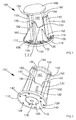
Figures 1 to 4 show a first embodiment of the anchor assembly, which is generally indicated 100. Theanchor assembly 100 includes abase member 110 which may be mounted to aform board 112 and a supportingmember 180 for location in thebase member 110. - Referring specifically to
Figure 3 , thebase member 110 comprises a mountingportion 114 in the form of a generally circular disc defining opposed upper and lower faces 116,118. Thelower face 118 is generally planar so as to sit squarely on the generally planar upper surface of aform board 112 used in creating the concrete substrate. - The
upper face 116 is provided with three annular ridges extending concentrically around a central region of thebase member 110 and each lying on a different radius to define inner, middle and outer annular ridges 120,122,124. Theupper face 116 is also provided with sixradial ridges 126 extending from the periphery of the central region towards the periphery of thebase member 110. Theradial ridges 126 are substantially equi-spaced and intersect the three annular ridges 120,122,124. These intersecting radial and annular ridges increase the rigidity of thebase member 110. Thebase member 110 is provided with six auxiliary throughholes 128 located at the intersection between the intermediateannular ridge 122 and eachradial ridge 126. These auxiliary throughholes 128 may optionally be used to secure thebase member 110 to theform board 112 using nails, screws or like fasteners (not shown). - A
guide member 130 extends upwardly from theupper face 116 of the mountingportion 114. Theguide member 130 is generally tubular with a circular cross-section and is located in the central region of thebase member 110 so as to be inside the innerannular ridge 120. Theguide member 130 has an uppercircumferential rim 132 which is castellated to define three equi-spacedtroughs 134 and three equi-spacedpeaks 136, the troughs being wider than the peaks. - The
base member 110 also includes three nail guides 140 equi-spaced around theguide member 130. Eachnail guide 140 is attached to theguide member 130 and extends upwardly from theupper surface 116 and terminates at arespective peak 136 of the castellated uppercircumferential rim 132. Eachnail guide 140 comprises a tubular body defining a circular passage which continues throughopenings 142 in the mountingportion 114. - The
base member 110 is strengthened by threelarge webs 150 arranged between arespective nail guide 140 and theupper surface 116. The top 152 of eachlarge web 150 extends slightly above itsrespective nail guide 140 and includes anotch 154 for accommodating thehead 158 of anail 160 received in thenail guide 140. Interposed between each pair oflarge webs 150 is asmall web 162 arranged between theguide member 130 and theupper face 116 of the mountingportion 114. The top of eachsmall web 162 locates slightly below arespective trough 134 of the castellatedcircumferential rim 132. - Referring now to
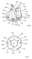
Figures 2 and4 , the central region of the mountingportion 114 of thebase member 110 is provided with aclosure member 168. In this embodiment, theclosure member 168 is delineated by fourarcuate slots 170 arranged end to end on a circle having a location and radius corresponding to those of the interior of theguide member 130. Theclosure member 168 remains attached to the mountingportion 114 by fourthreads 174 defined by the areas of the mountingportion 114 remaining between the ends of any two adjacentarcuate slots 170. The centre of theclosure member 168 is provided with connection means 176, such as a hexagonal recess, to facilitate rotation of theclosure member 168 by an appropriate tool. Thethreads 174 are sufficiently few and small to break upon rotation of theclosure member 168 to facilitate its detachment from the mountingportion 114. Theslots 170 are sufficiently narrow to restrict the ingress of concrete and other debris inside themain guide 130. - Referring now to
Figures 1 and 2 , there is shown thesupport member 180 located inside thebase member 110. Thesupport member 180 includes acylindrical shank 182 having ahead 184 at a first end and ablind bore 186 at a second end. The shank has a length and a diameter corresponding closely to the length and internal diameter of theguide member 130; the correspondingly sized diameters enable a snug fit to be achieved between theguide member 130 and thesupport member 180 so as to restrict the ingress of concrete therebetween. -
Figures 7 to 11 show a second embodiment of the anchor assembly. Many features of this second embodiment are also common to the first embodiment; as such, corresponding features in those embodiments will be given corresponding reference numerals and limited discussion of those will be given here in connection with this second embodiment. - The second embodiment of the
anchor assembly 200 includes abase member 210 and asupport member 280. Thebase member 210 includes a mountingportion 214 being substantially circular and having opposed upper and lower faces 216,218. Theupper face 116 is provided with radial and annular ridges 220,222,224,226, guide means 230, nail support means 240 and also large and small webs 250,262. - The
base member 210 includes aninsert 290 which locates in ashallow recess 291 in thelower face 218 of the mountingportion 214. Theinsert 290 and therecess 291 are of a similar size and shape so as to form a snug fit. Theinsert 290 is generally circular and includes anannular wall 292 arranged concentrically on its upper face. The portion of theinsert 290 inside theannular wall 292 comprises aclosure member 268 which is delineated by lines of weakness. In particular, theinsert 290 includes opposedannular grooves second sides insert 290. Eachside insert 290 includes sixradial grooves insert 290, thegrooves first side 294a of theinsert 290 being aligned withcorresponding grooves second side 294b of theinsert 290. The annular and radial grooves 293, 295 on the first andsecond sides insert 290 therefore define sixsegments 296 making up theclosure member 268. The portion of theinsert 290 located between a pair of opposed grooves on the first and second sides 294,294b is relatively thin so as to form a frangible joint which may be broken with sufficient force. - The
first side 294a of theinsert 290 is provided with sixprotuberances 297 spaced equidistantly around theannular wall 292, those protuberances in this example comprising arrows directed to the centre of theinsert 290. Between each pair ofadjacent protuberances 297 there is provided aweb 298 upstanding from thefirst side 294a and joining theannular wall 292. Three of thewebs 298 are provided withbosses 299 which align with the nail guides 240 on theguide member 230 and include through holes to allow the passage of nails 260 through theinsert 290. - The
shallow recess 291 is shaped to receive the various features of theinsert 290. In particular, theshallow recess 291 includes sixapertures 285 and six slots (not shown) arranged alternately so as to receive the respective alternatingprotuberances 297 andwebs 298 of theinsert 290. The slots are blind such that thewebs 298 do not extend through the mountingportion 214, but theapertures 285 are open so as to allow theprotuberances 297 to extend beyond the mountingportion 214. Theprotuberances 297 indicate when theinsert 290 and mountingportion 214 are located squarely on the form board (not shown) by extending fully into theapertures 285, but not beyond. - The
guide member 230 is provided with three axial channels and three axial ribs which hare arranged in an alternating fashion on the internal face of said guide member. Each channel is aligned with a respective trough and each rib is aligned with a respective peak. The channels are tapered such that their cross-sectional area increases towards the upper circumferential rim. The ribs are configured to deform slightly as the support member is inserted into the guide member so as to provide an interference to resist inadvertent disassembly. - The
annular wall 292 locates partway into theguide member 230 and the top face of the annular wall defines ashoulder 287 against which thesecond end 281 of thesupport member 280 may bear. - In use, once the concrete has set over the
anchor assembly 200 and the form board is removed, theclosure member 268 may be gently struck so as to cause the sixsegments 296 to break away from theinsert 290. The threaded bore (not shown, but comparable to threadedbore 186 of the first embodiment) of thesupport member 280 may then be accessed through theannular wall 292. - A third embodiment of the invention will now be described with reference to
Figures 12 and 13 . Again, there are many features of this embodiment which are also common to the first and second embodiments. Therefore, common features have been given corresponding reference numerals. - The third embodiment of the
anchor assembly 300 includes abase member 310 and asupport member 380. Thebase member 310 includes a mountingportion 314 being substantially circular and having opposed upper and lower surfaces 316,318. The upper surface 316 is provided withguide member 330,nail support member 350 and also large and small webs 350,362. - The base member includes a shallow recess in its lower face. In this embodiment, the shallow recess is concaved with a very large radius of curvature compared to the radius of the base member. The shallow recess serves to increase the sealing between the base member and form board so as to protect the closure member from wet concrete being poured onto the form board. In particular, as the base member is nailed to the form board, the recess diminishes and the outer periphery of the base member becomes under increased tension against the form board.
- The closure member 368 is arranged in the centre of the
lower face 318 of the mountingportion 314 so as to be directly below the internal bore of theguide member 330. The closure member 368 in this embodiment is polygonal so as to include a plurality ofedges 400 forming its periphery. The closure member 368 is defined by a very thin portion of the mountingportion 314 and delineated by opposedperipheral grooves radial grooves 395a,395b are provided on the upper and lower faces 316,318 so as to divide the closure member 368 into a plurality ofsegments 396 corresponding to the plurality of sides of the chosen polygon. The material remaining between any pair of opposed grooves 393,395 on the upper and lower faces 316,318 is very thin so as to form a frangible joint. - The interior of the
guide member 330 immediately above the closure member 368 has a polygonal cross-sectional shape corresponding to the polygonal shape of the closure member 368. The internal shape of theguide member 330 transitions from polygonal to circular a short distance above the closure member 368. The transition defines ashoulder 400 against which thesupport member 380 may bear once located in theguide member 330. - In use, once the concrete has set over the
anchor assembly 300 and the form board is removed, the closure member 368 may be gently struck so as to cause the plurality ofsegments 396 to break away from the mountingportion 314. The threaded bore of thesupport member 380 may then be accessed through the opening into theguide member 330.
Claims (15)
- A base member connectable to a support member to form an anchor assembly mountable to a form board on which wet concrete may be poured during formation of a concrete substrate, the base member comprising:- a mounting portion for mounting the anchor assembly to the form board;- a main guide having first and second generally opposed ends, the first end being open to facilitate insertion of the support member into the main guide; and- removeable closing means configured at least partially to restrict access into the main guide via the second end, said closing means being removable to allow access into the main guide via the second end.
- A base member as claimed in claim 1, wherein the closing means is integral to the mounting portion and or the main guide.
- A base member as claimed in claim 2, wherein the closing means is delineated by a line of weakness.
- A base member as claimed in claim 2, wherein the mounting portion or the main guide includes at least one slot delineating the closing means.
- A base member as claimed in claim 2, wherein the closing means comprises a frangible part of the mounting portion or guide means.
- A base member as claimed in any preceding claim, wherein the mounting portion includes a removable insert.
- A base member as claimed in claim 6, wherein the removable insert includes at least one protuberance and the mounting portion includes at least one opening in which the protuberance locates to indicate correct placement of the base member.
- A base member as claimed in claim 6 or claim 7, wherein the closing means is provided on the removable insert.
- A base member as claimed in any preceding claim, wherein the main guide includes at least one channel to allow the evacuation of air during insertion of the mounting support member.
- A base member as claimed in any preceding claim, wherein the interior of the main guide narrows at or towards the second end to define a shoulder against which the support member may bear.
- A base member as claimed in any preceding claim, and further comprising at least one reinforcement web arranged between the main guide and the mounting portion.
- A base member as claimed in any preceding claim, wherein the main guide includes at least one rib adapted for engagement with the support member.
- A base member as claimed in any preceding claim, wherein the mounting portion has an underside provided with a shallow recess which is arranged to diminish as the base member is fastened to the form board.
- A cast in place anchor assembly comprising:a base member as claimed in any preceding claim; anda support member located in the main guide of the base member and provided with attachment means accessible through the second end of the main guide upon removal of the closing means.
- A method of creating a concrete substrate, the method comprises the steps of:- providing a form board having an upper surface;- resting on the form board an anchor assembly comprising:- a base member having a mounting portion, guide means and closing means; and- a support member located in the guide means;- pouring concrete over the form board and the anchor assembly; and- removing the form board, characterised by the further step of removing the closing means of the anchor assembly so as to provide access to the support member.
Priority Applications (6)
| Application Number | Priority Date | Filing Date | Title |
|---|---|---|---|
| EP16156770.6A EP3208397A1 (en) | 2016-02-22 | 2016-02-22 | Anchor assembly and base member therefor |
| CA2958383A CA2958383A1 (en) | 2016-02-22 | 2017-02-17 | Base member for an anchor assembly and method of use |
| AU2017201118A AU2017201118A1 (en) | 2016-02-22 | 2017-02-20 | Base member for an anchor assembly and method of use |
| EP17156943.7A EP3208398B1 (en) | 2016-02-22 | 2017-02-20 | Base member for an anchor assembly and method of use |
| US15/437,955 US10151102B2 (en) | 2016-02-22 | 2017-02-21 | Base member for an anchor assembly and method of use |
| US16/178,713 US10519648B2 (en) | 2014-02-26 | 2018-11-02 | Base member for an anchor assembly and method of use |
Applications Claiming Priority (1)
| Application Number | Priority Date | Filing Date | Title |
|---|---|---|---|
| EP16156770.6A EP3208397A1 (en) | 2016-02-22 | 2016-02-22 | Anchor assembly and base member therefor |
Publications (1)
| Publication Number | Publication Date |
|---|---|
| EP3208397A1 true EP3208397A1 (en) | 2017-08-23 |
Family
ID=55456595
Family Applications (2)
| Application Number | Title | Priority Date | Filing Date |
|---|---|---|---|
| EP16156770.6A Withdrawn EP3208397A1 (en) | 2014-02-26 | 2016-02-22 | Anchor assembly and base member therefor |
| EP17156943.7A Active EP3208398B1 (en) | 2016-02-22 | 2017-02-20 | Base member for an anchor assembly and method of use |
Family Applications After (1)
| Application Number | Title | Priority Date | Filing Date |
|---|---|---|---|
| EP17156943.7A Active EP3208398B1 (en) | 2016-02-22 | 2017-02-20 | Base member for an anchor assembly and method of use |
Country Status (4)
| Country | Link |
|---|---|
| US (2) | US10151102B2 (en) |
| EP (2) | EP3208397A1 (en) |
| AU (1) | AU2017201118A1 (en) |
| CA (1) | CA2958383A1 (en) |
Families Citing this family (10)
| Publication number | Priority date | Publication date | Assignee | Title |
|---|---|---|---|---|
| EP3208397A1 (en) * | 2016-02-22 | 2017-08-23 | Black & Decker Inc. | Anchor assembly and base member therefor |
| US10577816B1 (en) | 2016-02-18 | 2020-03-03 | Cetres Holdings, Llc | Holder for supporting an anchor rod and anchor body |
| EP3382118B1 (en) * | 2017-03-31 | 2023-06-07 | Black & Decker Inc. | Cast-in-place anchors |
| EP3692221A1 (en) | 2017-10-06 | 2020-08-12 | Hilti Aktiengesellschaft | Systems and methods for a cast-in anchor |
| KR102021258B1 (en) * | 2019-01-22 | 2019-09-11 | 한전케이피에스 주식회사 | Rapper Assembly for improving the fixing method of coils |
| US20200325924A1 (en) * | 2019-04-12 | 2020-10-15 | Black & Decker Inc. | Cast-in place anchor with multi-use jaws and removable nose-piece |
| EP4124768A1 (en) | 2021-07-26 | 2023-02-01 | Hilti Aktiengesellschaft | Threaded rod connector with threadless contact surfaces |
| USD992404S1 (en) * | 2021-08-16 | 2023-07-18 | Gripple Limited | Anchor device |
| USD994478S1 (en) * | 2021-08-16 | 2023-08-08 | Gripple Limited | Anchor device |
| WO2023220334A1 (en) * | 2022-05-13 | 2023-11-16 | Cetres Holdings, Llc | Adjustable rod holder for concrete construction |
Citations (6)
| Publication number | Priority date | Publication date | Assignee | Title |
|---|---|---|---|---|
| JPH0227405U (en) * | 1988-04-01 | 1990-02-22 | ||
| WO1995013436A1 (en) * | 1993-11-12 | 1995-05-18 | Oike Co., Ltd. | Buried concrete product |
| US20130067849A1 (en) * | 2011-03-18 | 2013-03-21 | Thomas M. Espinosa | Concrete Anchor Coupling Assembly and Anchor Rod Holder |
| US20140157717A1 (en) * | 2012-08-06 | 2014-06-12 | Thomas M. Espinosa | Holder and Concrete Anchor Assemblies |
| US20150184373A1 (en) * | 2012-08-20 | 2015-07-02 | Thomas M. Espinosa | Anchor holders and anchor assemblies for metal decks |
| WO2015140969A1 (en) * | 2014-03-19 | 2015-09-24 | 株式会社Aoi | Insert fitting |
Family Cites Families (8)
| Publication number | Priority date | Publication date | Assignee | Title |
|---|---|---|---|---|
| US3405497A (en) * | 1966-08-08 | 1968-10-15 | Lloyd L. Mcnair | Suspension device for ceilings and fixtures |
| US4170853A (en) * | 1977-09-30 | 1979-10-16 | Raceway Components, Inc. | Insert void forming device |
| US4211048A (en) * | 1978-11-17 | 1980-07-08 | Kabushiki Kaisha Mikado | Concrete anchor |
| US6135687A (en) * | 1999-07-02 | 2000-10-24 | Simpson Strong-Tie Co., Inc. | Direct tension indicator for embedded anchor members |
| US6240697B1 (en) * | 2000-03-15 | 2001-06-05 | William J. Thompson | Threaded anchor for poured concrete metal deck floors and wood frame floors |
| CA2918187C (en) * | 2012-07-24 | 2018-01-16 | Thomas M. Espinosa | Holder for concrete anchors |
| US9394706B2 (en) * | 2013-10-08 | 2016-07-19 | Simpson Strong-Tie Company, Inc. | Concrete anchor |
| EP3208397A1 (en) * | 2016-02-22 | 2017-08-23 | Black & Decker Inc. | Anchor assembly and base member therefor |
-
2016
- 2016-02-22 EP EP16156770.6A patent/EP3208397A1/en not_active Withdrawn
-
2017
- 2017-02-17 CA CA2958383A patent/CA2958383A1/en not_active Abandoned
- 2017-02-20 AU AU2017201118A patent/AU2017201118A1/en not_active Abandoned
- 2017-02-20 EP EP17156943.7A patent/EP3208398B1/en active Active
- 2017-02-21 US US15/437,955 patent/US10151102B2/en active Active
-
2018
- 2018-11-02 US US16/178,713 patent/US10519648B2/en active Active
Patent Citations (6)
| Publication number | Priority date | Publication date | Assignee | Title |
|---|---|---|---|---|
| JPH0227405U (en) * | 1988-04-01 | 1990-02-22 | ||
| WO1995013436A1 (en) * | 1993-11-12 | 1995-05-18 | Oike Co., Ltd. | Buried concrete product |
| US20130067849A1 (en) * | 2011-03-18 | 2013-03-21 | Thomas M. Espinosa | Concrete Anchor Coupling Assembly and Anchor Rod Holder |
| US20140157717A1 (en) * | 2012-08-06 | 2014-06-12 | Thomas M. Espinosa | Holder and Concrete Anchor Assemblies |
| US20150184373A1 (en) * | 2012-08-20 | 2015-07-02 | Thomas M. Espinosa | Anchor holders and anchor assemblies for metal decks |
| WO2015140969A1 (en) * | 2014-03-19 | 2015-09-24 | 株式会社Aoi | Insert fitting |
Also Published As
| Publication number | Publication date |
|---|---|
| AU2017201118A1 (en) | 2017-09-07 |
| EP3208398A1 (en) | 2017-08-23 |
| US10519648B2 (en) | 2019-12-31 |
| EP3208398B1 (en) | 2021-10-06 |
| US20190194933A1 (en) | 2019-06-27 |
| US10151102B2 (en) | 2018-12-11 |
| CA2958383A1 (en) | 2017-08-22 |
| US20170241129A1 (en) | 2017-08-24 |
Similar Documents
| Publication | Publication Date | Title |
|---|---|---|
| EP3208397A1 (en) | Anchor assembly and base member therefor | |
| EP3824145B1 (en) | Systems and methods for a cast-in anchor for a metal deck | |
| US4943100A (en) | Drain suited for installation in wooden floors | |
| US20210131480A1 (en) | Snap nut concrete anchor assembly | |
| US7805777B2 (en) | Closet flange spacer | |
| US4648139A (en) | Mounting ring assembly for a toilet bowl | |
| KR20190060956A (en) | Magnetic type embeded anchor and manufacturing method thereof | |
| US6725611B2 (en) | Sleeve holder for utility conduit | |
| WO2013040585A2 (en) | Anchor bolt devices and operating methods for residential and commercial structures | |
| NZ729173A (en) | Base member for an anchor assembly and method of use | |
| EP3757315A1 (en) | Formwork insert | |
| US7958686B1 (en) | Drain body support pan | |
| KR20040027856A (en) | Insert for concrete slave | |
| JP6246575B2 (en) | Post-construction anchor, anchor tool and construction method | |
| ITFO980031A1 (en) | UNIVERSAL BUILT-IN BOX FOR LIGHTING SPOTLIGHTS AND RELATED TOOL FOR INSTALLATION. | |
| KR100536430B1 (en) | Fixing way of subsidiary materials for a building and the structure | |
| KR200482271Y1 (en) | Concrete buried fastener | |
| WO2011032211A1 (en) | Improved fire collars | |
| KR200335422Y1 (en) | Fixing structure of subsidiary materials for a building | |
| JPH03241190A (en) | Adapter for embedded nut for steel pipe concrete utility pole | |
| NO345772B1 (en) | Method for mounting a floor drain assembly and a floor drain assembly | |
| KR20160109100A (en) | Insert for anchor bolt | |
| KR20100011175U (en) | Fixing tool heating insulator for preventing forming dew | |
| JPH06146312A (en) | Reformable foot-holder | |
| JP2010261492A (en) | Anchor nut and method for installing road marker |
Legal Events
| Date | Code | Title | Description |
|---|---|---|---|
| PUAI | Public reference made under article 153(3) epc to a published international application that has entered the european phase |
Free format text: ORIGINAL CODE: 0009012 |
|
| AK | Designated contracting states |
Kind code of ref document: A1 Designated state(s): AL AT BE BG CH CY CZ DE DK EE ES FI FR GB GR HR HU IE IS IT LI LT LU LV MC MK MT NL NO PL PT RO RS SE SI SK SM TR |
|
| AX | Request for extension of the european patent |
Extension state: BA ME |
|
| STAA | Information on the status of an ep patent application or granted ep patent |
Free format text: STATUS: THE APPLICATION IS DEEMED TO BE WITHDRAWN |
|
| 18D | Application deemed to be withdrawn |
Effective date: 20180224 |