EP3208193A1 - Vorrichtung und methode zur steuerung einer kupplung zwischen dem motor und dem hauptleistungsübertragungsgetriebe eines luftfahrzeugs - Google Patents
Vorrichtung und methode zur steuerung einer kupplung zwischen dem motor und dem hauptleistungsübertragungsgetriebe eines luftfahrzeugs Download PDFInfo
- Publication number
- EP3208193A1 EP3208193A1 EP17154757.3A EP17154757A EP3208193A1 EP 3208193 A1 EP3208193 A1 EP 3208193A1 EP 17154757 A EP17154757 A EP 17154757A EP 3208193 A1 EP3208193 A1 EP 3208193A1
- Authority
- EP
- European Patent Office
- Prior art keywords
- btp
- coupling mechanism
- engine
- measurement
- clutch
- Prior art date
- Legal status (The legal status is an assumption and is not a legal conclusion. Google has not performed a legal analysis and makes no representation as to the accuracy of the status listed.)
- Granted
Links
- 238000000034 method Methods 0.000 title claims abstract description 33
- 230000005540 biological transmission Effects 0.000 title claims abstract description 9
- 230000008878 coupling Effects 0.000 claims abstract description 154
- 238000010168 coupling process Methods 0.000 claims abstract description 154
- 238000005859 coupling reaction Methods 0.000 claims abstract description 154
- 230000007246 mechanism Effects 0.000 claims abstract description 139
- 238000005259 measurement Methods 0.000 claims description 81
- 230000001050 lubricating effect Effects 0.000 claims description 55
- 239000007788 liquid Substances 0.000 claims description 52
- 230000001276 controlling effect Effects 0.000 claims description 33
- 230000009471 action Effects 0.000 claims description 13
- 239000002826 coolant Substances 0.000 claims description 12
- 230000033228 biological regulation Effects 0.000 claims description 10
- 230000000295 complement effect Effects 0.000 claims description 10
- 238000012360 testing method Methods 0.000 claims description 10
- 230000006870 function Effects 0.000 claims description 8
- 230000001105 regulatory effect Effects 0.000 claims description 6
- 230000004913 activation Effects 0.000 claims description 4
- HVGNSPLLPQWYGC-UHFFFAOYSA-N 2,3-dihydroxy-6-propan-2-ylcyclohepta-2,4,6-trien-1-one Chemical compound CC(C)C=1C=CC(O)=C(O)C(=O)C=1 HVGNSPLLPQWYGC-UHFFFAOYSA-N 0.000 claims 16
- 230000006835 compression Effects 0.000 description 9
- 238000007906 compression Methods 0.000 description 9
- 238000010586 diagram Methods 0.000 description 5
- 238000005457 optimization Methods 0.000 description 5
- 238000005461 lubrication Methods 0.000 description 4
- 238000002485 combustion reaction Methods 0.000 description 3
- 239000012530 fluid Substances 0.000 description 3
- 239000000446 fuel Substances 0.000 description 3
- 230000015556 catabolic process Effects 0.000 description 2
- 238000010276 construction Methods 0.000 description 2
- 238000006731 degradation reaction Methods 0.000 description 2
- 239000007789 gas Substances 0.000 description 2
- 238000009434 installation Methods 0.000 description 2
- 238000012423 maintenance Methods 0.000 description 2
- 230000003287 optical effect Effects 0.000 description 2
- 238000013459 approach Methods 0.000 description 1
- 230000000903 blocking effect Effects 0.000 description 1
- 238000009529 body temperature measurement Methods 0.000 description 1
- 230000008859 change Effects 0.000 description 1
- 230000007423 decrease Effects 0.000 description 1
- 230000006866 deterioration Effects 0.000 description 1
- 238000011161 development Methods 0.000 description 1
- 238000006073 displacement reaction Methods 0.000 description 1
- 230000010006 flight Effects 0.000 description 1
- 238000002347 injection Methods 0.000 description 1
- 239000007924 injection Substances 0.000 description 1
- 230000033001 locomotion Effects 0.000 description 1
- 238000002360 preparation method Methods 0.000 description 1
- 238000003825 pressing Methods 0.000 description 1
- 238000004088 simulation Methods 0.000 description 1
- 239000007787 solid Substances 0.000 description 1
- 238000012546 transfer Methods 0.000 description 1
- 238000010200 validation analysis Methods 0.000 description 1
- 238000012795 verification Methods 0.000 description 1
- 230000000007 visual effect Effects 0.000 description 1
- 238000012800 visualization Methods 0.000 description 1
Images


Classifications
-
- B—PERFORMING OPERATIONS; TRANSPORTING
- B64—AIRCRAFT; AVIATION; COSMONAUTICS
- B64D—EQUIPMENT FOR FITTING IN OR TO AIRCRAFT; FLIGHT SUITS; PARACHUTES; ARRANGEMENTS OR MOUNTING OF POWER PLANTS OR PROPULSION TRANSMISSIONS IN AIRCRAFT
- B64D31/00—Power plant control; Arrangement thereof
- B64D31/14—Transmitting means between initiating means and power plants
-
- B—PERFORMING OPERATIONS; TRANSPORTING
- B64—AIRCRAFT; AVIATION; COSMONAUTICS
- B64C—AEROPLANES; HELICOPTERS
- B64C27/00—Rotorcraft; Rotors peculiar thereto
- B64C27/04—Helicopters
- B64C27/12—Rotor drives
-
- B—PERFORMING OPERATIONS; TRANSPORTING
- B64—AIRCRAFT; AVIATION; COSMONAUTICS
- B64D—EQUIPMENT FOR FITTING IN OR TO AIRCRAFT; FLIGHT SUITS; PARACHUTES; ARRANGEMENTS OR MOUNTING OF POWER PLANTS OR PROPULSION TRANSMISSIONS IN AIRCRAFT
- B64D31/00—Power plant control; Arrangement thereof
- B64D31/02—Initiating means
- B64D31/04—Initiating means actuated personally
-
- B—PERFORMING OPERATIONS; TRANSPORTING
- B64—AIRCRAFT; AVIATION; COSMONAUTICS
- B64D—EQUIPMENT FOR FITTING IN OR TO AIRCRAFT; FLIGHT SUITS; PARACHUTES; ARRANGEMENTS OR MOUNTING OF POWER PLANTS OR PROPULSION TRANSMISSIONS IN AIRCRAFT
- B64D31/00—Power plant control; Arrangement thereof
- B64D31/02—Initiating means
- B64D31/06—Initiating means actuated automatically
-
- B—PERFORMING OPERATIONS; TRANSPORTING
- B64—AIRCRAFT; AVIATION; COSMONAUTICS
- B64D—EQUIPMENT FOR FITTING IN OR TO AIRCRAFT; FLIGHT SUITS; PARACHUTES; ARRANGEMENTS OR MOUNTING OF POWER PLANTS OR PROPULSION TRANSMISSIONS IN AIRCRAFT
- B64D35/00—Transmitting power from power plant to propellers or rotors; Arrangements of transmissions
- B64D35/08—Transmitting power from power plant to propellers or rotors; Arrangements of transmissions characterised by the transmission being driven by a plurality of power plants
Definitions
- This engine may include one or more internal combustion engines of different types, such as a piston engine or a gas turbine also called turbine engine.
- a turbine engine comprises in principle several stages of compression of the intake air, a combustion chamber and a multi-stage expansion turbine. Each stage of the expansion turbine is rotated by the gases from the combustion. A turbine engine can then be linked turbine or free turbine.
- the expansion turbine In a free-turbine turbine engine, the expansion turbine generally comprises firstly the first expansion stages integral with the compression stages and secondly the last stages of expansion integral with the output shaft.
- the first stages of the expansion turbine are therefore not mechanically linked to the last stages of the expansion turbine, but are linked to the compressor shaft.
- the compression stages are rotated by the first stages of the expansion turbine while the output shaft is driven by the last stages of the expansion turbine constituting the free turbine. In fact, no mechanical coupling exists between the output shaft of a free-turbine turbine engine and the compression stages of this turbine engine.
- the output shaft is integral with the crankshaft which is rotated by the displacement of the pistons. There is therefore a mechanical coupling of the output shaft with the crankshaft and pistons piston engine.
- BTP main gearbox mechanical power
- a coupling mechanism of the clutch type is then generally arranged between the output shaft of each engine and the BTP.
- Each engine is thus started alone, without causing rotation of the main rotor.
- the main rotor and possibly the anti-torque rotor are trained progressively in rotation through the coupling mechanism.
- This coupling mechanism is actuated by a pilot of the aircraft for example by means of a lever arranged in the cockpit of the aircraft.
- This coupling mechanism can also be used when stopping the engine to mechanically decouple the output shaft of the engine and the BTP, thus avoiding that the main rotor causes rotation of the engine after stopping.
- This coupling mechanism may for example be a belt clutch used for example on rotary wing aircraft called “ultra light”.
- the belt clutch is actuated by a pilot of the aircraft and the main rotor drive by the output shaft of the engine is then done gradually to prevent the engine stalls.
- the coupling mechanism may also be a centrifugal clutch whose coupling is automatic and linked to the speed of rotation of the engine.
- a coupling system makes it possible to start the aircraft in two phases: firstly, a first phase of actual starting of the engine whose output shaft is mechanically decoupled from the BTP, then a second phase of mechanical coupling of the motor output shaft with an input shaft of the BTP.
- the BTP is particularly vulnerable when coupled with the engine.
- the lubrication of this BTP is usually performed by pumps driven by the BTP itself. In fact, this lubrication is not effective as long as the BTP is not rotated. The lubrication is then effective gradually when the BTP is rotated. Thus, a coupling too fast between the engine and the BTP can cause the BTP at high speeds of rotation while its lubrication is not fully effective and then degrade the components of this BTP.
- the power of the motorization is progressively transmitted to the BTP.
- the control of the torque and the speed of rotation of the engine during this second mechanical coupling phase must be carried out manually by the driver, which for example changes the fuel flow injected into the engine.
- the instruction of the pilot is then to control the injection of fuel to maintain a rotation speed of the motorization sufficient to drive the BTP and prevent the engine to stall.
- each engine is controlled by a control system for example to manage the start phase and / or regulate its rotation speed.
- control system was a purely mechanical or hydromechanical system.
- This FADEC engine calculator also makes it possible to determine the current operating limits of the engine, taking into account the flight conditions and various information resulting from the operation of the engine of the aircraft and its environment.
- the present invention aims to overcome the limitations mentioned above and to facilitate the starting of the engine of an aircraft, particularly when the engine is a piston engine or a turboshaft turbine linked.
- the present invention notably makes it possible to significantly reduce the risk of damage to the BTP during this starting phase of the engine by assisting or by automating the coupling phase of the engine to the BTP.
- the present invention therefore relates to a device and a method for controlling a coupling mechanism between a motor and a main gearbox BTP mechanical power and a power plant provided with such a control device.
- This method and this control device of a coupling mechanism according to the invention are in particular intended for a power plant of a rotary wing aircraft.
- Such a control method for controlling a coupling mechanism according to the invention between a motor and a main gearbox BTP mechanical power is for an aircraft.
- the aircraft comprises at least one engine, a BTP and at least one coupling mechanism, a coupling mechanism being arranged between each engine and the BTP and for securing an output shaft of each engine with an input shaft of the engine. BTP.
- Each engine, each control system, each coupling mechanism and the BTP form the power plant of the aircraft.
- the determination of a state of a motorization makes it possible to define whether the motorization has reached nominal operating conditions in order to allow the clutch of the coupling means and consequently the securing of the output shaft of the motorization and the motor. input shaft of the BTP.
- the motorization may at least stall during clutch or to be degraded.
- the engine may be a turbine turbine engine linked.
- the determination of a state of the engine comprises only a first measurement of the first speed of rotation of the connected turbine.
- the verification that this turbine engine has reached a first speed of rotation of the connected turbine close to a set speed of rotation is the main criterion for verifying that the nominal operating conditions are reached.
- the engine can also be a piston engine using for example as fuel gasoline or diesel.
- the determination of a state of a motorization comprises firstly a first measurement of the first rotational speed of the output shaft of the piston engine and secondly a second measurement of the temperature of the engine.
- a piston engine coolant and a third measurement of the temperature of a first piston engine lubricating fluid are included in the piston engine.
- This determination of the state of the engine can be performed by a first means for determining a state of a motorization.
- This first means for determining a state of a motor then comprises, when the engine is a turbine turbine engine linked, a first speed sensor measuring for example a first rotational speed of the shaft of rotation of the turbine connected.
- this first means for determining a state of a motorization comprises a first speed sensor measuring for example a first rotational speed of the output shaft of the piston engine and a second and a third temperature sensor respectively measuring the temperature of the coolant and the first piston engine lubricating fluid.
- this first means of determining a state of a motorization can be integrated into the control system of this engine, this control system can have these measures of the first speed of rotation of the engine and if necessary of temperatures of the coolant and the first lubricating liquid.
- the determination of a state "ready to engage” for the coupling mechanism related to the motorization can then be performed if the operating conditions are nominal. This determination of the "ready to engage” state is performed by checking at least that a difference between the first speed of rotation of the actuator and the set speed of rotation is less than or equal to a first threshold.
- determining a "ready to engage" state is performed by also verifying that the second measurement of the coolant temperature of the engine is located in a first temperature range of operation and the third measurement of the temperature of the first lubricating liquid is in a second operating temperature range.
- the first and second intervals are determined during testing and development of the piston engine.
- the first threshold is 2100 rpm
- the first range is 60 ° C and 110 ° C
- the second range is 50 ° C and 130 ° C.
- first and the second intervals may be intervals comprising a single defined boundary, preferably the lower bound.
- first interval contains temperatures greater than or equal to 60 ° C and the second interval contains temperatures greater than or equal to 50 ° C.
- This set speed of the motorization can correspond to a nominal speed of rotation of the main rotor or to an idle speed of this main rotor.
- This determination of the "ready to engage” state can be performed by the first means for determining a state of a motorization. This determination of the "ready to engage” state can also be carried out by a second means for determining a "ready to engage” state.
- the clutch of the coupling mechanism is performed automatically when the "ready to engage" state is determined and after validation by a pilot of the aircraft.
- the method according to this second embodiment comprises different complementary steps located between the determination of a "ready to engage” state and the clutch of the coupling mechanism.
- a complementary first step of providing by an information means of the aircraft information "ready to engage” with a pilot of the aircraft is performed as soon as the "ready to engage” state is determined.
- a second complementary step of activation by the pilot of a clutch order of the coupling mechanism via a means of action arranged in a cockpit of the aircraft is performed.
- the information means may be a visualization means, such as a screen or a light, displaying the information "ready to engage”.
- This information medium can also provide this information in sound form.
- the means of action is for example a push button arranged on the dashboard of the aircraft. The pilot thus chooses, by acting on the means of action once he has read the information "ready to engage", the start time of the clutch operation of the coupling mechanism.
- the clutch is thus realized automatically via the clutch control means of the coupling mechanism as soon as these two conditions are met, namely the determination of the "ready to engage" state and the activation. by the pilot of the course of action.
- the means of action provides for example a clutch signal, in electrical or optical form, to the control means.
- the progress of the clutch is again automatically managed by a control means to avoid the setting of the engine and too much torque provided by the engine.
- This second embodiment advantageously makes it possible to unload the pilot of the aircraft from this task of managing the clutch and also to secure this clutch operation.
- the pilot can choose the moment of the attachment of the engine with the BTP in order to avoid for example to cause the BTP in rotation while the takeoff of the aircraft is not imminent.
- the engine can be started so that the rotary wing aircraft is powered electrically for example to prepare the flight without the main rotor is rotated.
- the clutch coupling mechanism is performed manually by the pilot of the aircraft when the "ready to engage” state is determined.
- the method according to this third embodiment comprises a complementary step located between the determination of a "ready to engage” state and the clutch of the coupling mechanism.
- This complementary step is the provision by an information means of the aircraft information "ready to engage” as soon as the "ready to engage” state is determined.
- "gear-to-gear” information can be provided in a visual or audible form.
- the clutch of the coupling mechanism is then performed manually by a pilot via a clutch lever arranged in a cockpit of the aircraft.
- the clutch control means of the coupling mechanism comprises the clutch lever.
- the control method for controlling a coupling mechanism according to the invention advantageously makes it possible to limit the risk of stalling the motorization, or even to avoid this stalling and, secondly, a too high torque provided by the motorization and likely to lead to deterioration, particularly on the BTP, the motorization or the coupling mechanism.
- the clutch of the coupling mechanism is performed automatically by the control means.
- the regulation of the coupling mechanism can be performed according to the first speed of rotation of the motor and the speed of rotation of the engine.
- the clutch speed is by default equal to a predefined maximum speed and is kept equal to this predefined maximum speed as long as the difference between the engine speed and the first rotational speed is less than or equal to a second predefined threshold.
- This clutch speed can then be reduced if the first rotational speed decreases and moves away from the target rotational speed, the difference between the set speed of rotation and the first speed of rotation becoming greater than this second threshold. predefined.
- This second threshold may be equal to the first threshold.
- the coupling mechanism during the clutch operation can also be controlled by driving a clutch position.
- clutch position refers to the position of the moving components of the coupling mechanism.
- this clutch position is the relative position of the disks forming this coupling mechanism, these disks being respectively secured to the output shaft of the motor and the input shaft of construction.
- the clutch speed is constant and predefined when this clutch position changes or is zero when the clutch position does not change.
- the fifth measurement of the pressure of the second lubricating liquid of the BTP can be replaced by a sixth measurement of the second rotation speed of the BTP.
- the second lubricating liquid of the BTP is driven by a pump itself rotated by the BTP.
- a third rotational speed of this pump can make it possible to quantify the pressure of the lubricating liquid and is proportional to the second rotation speed of the BTP.
- this sixth measurement of the second rotation speed of the BTP makes it possible to quantify the pressure of the lubricating liquid of the BTP.
- the maximum permissible torque by the BTP can then be determined from this sixth measurement of the second rotation speed of the BTP and the fourth measurement of the temperature of the second lubricating liquid of the BTP.
- This sixth measurement of the second rotation speed of the BTP is carried out via a sixth speed sensor.
- the determination of the maximum permissible torque by the BTP can be performed only from a fifth measurement of the pressure of the second lubricating liquid. of construction.
- the maximum permissible torque is then equal to a reduced torque if the fifth measurement of the pressure of the second lubricating liquid is less than or equal to a fourth threshold while the maximum admissible torque is equal to a maximum torque if the fifth measurement of the pressure second lubricating liquid is greater than the fourth threshold.
- the clutch of the coupling mechanism linked to the motorization the determination of the maximum permissible torque by the BTP and the regulation of the motorization are carried out simultaneously.
- the subject of the present invention is also a device for controlling a coupling mechanism between an engine and a main mechanical power transmission gearbox BTP intended for an aircraft, the aircraft comprising at least one engine, a control system for each motorization, a BTP and at least one coupling mechanism, a coupling mechanism arranged between each engine and the BTP for securing an output shaft of the engine with an input shaft of the BTP.
- the present invention also relates to a power plant for a rotary wing aircraft.
- This power plant comprises at least one motor, a control system for each engine, a main gearbox of mechanical power, at least one coupling mechanism and a control device of each coupling mechanism as previously described.
- a coupling mechanism is arranged between each engine and the BTP and allows to secure an output shaft of each engine with an input shaft of the BTP.
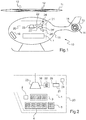
- a coupling mechanism 22,22 ' is arranged between each motor 21,21' and the BTP 23.
- Each coupling mechanism 22,22 'thus allows to secure an output shaft 25,25' of a motor 21,21 ' with an input shaft 26 of the MGB 23. In this way, each motor 21,21 'can drive in rotation the first blades 12 of the main rotor 11 and the second blades 14 of the anti-torque rotor 13 when the coupling mechanism 22, 22 'is engaged.
- Each device 1 for controlling a coupling mechanism 22, 22 ' comprises a first means 3 for determining a state of each motor 21, 21', a second means for determining a state "ready to engage” for each coupling mechanism 22,22 ', a third means 4 for determining a maximum allowable torque by the BTP 23 and a driving means 2 for the clutch of the coupling mechanism 22,22' linked to each motor 21,21 ' .
- a first power plant 20 is shown on the figure 2 and comprises a motor 21, which is a piston engine, a control system 24 of the piston engine 21, a coupling mechanism 22 arranged between the output shaft 25 of the piston engine 21 and the engine shaft. input 26 of the BTP 23 and a device 1 for controlling the coupling mechanism 22.
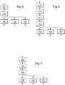
- This device 1 for controlling the coupling mechanism 22 can implement the method whose synoptic diagram is shown in FIG. figure 5 and which has five steps.
- the first determination means 3 comprises a first speed sensor 31 intended to measure a first rotational speed of the output shaft 25 of the piston engine 21, a second temperature sensor 32 intended to measure a second measurement of the temperature of the engine. a coolant of the piston engine 21 and a third temperature sensor 33 for measuring a third measurement of the temperature of a first lubricating liquid of the piston engine 21.
- the first determining means 3 delivers the first rotational speed of the output shaft 25 of the piston engine 21, the second measurement of the coolant temperature of the piston engine 21 and the third measurement of the temperature of the first lubricating fluid of the piston engine 21 characterizing a state of the piston engine 21.
- the second determining means 5 comprises a comparator 51 in order to compare the first measurement of the first rotational speed of the output shaft 25 of the piston engine 21 with a set rotation speed of this output shaft 25, the second measuring the coolant temperature of the piston engine 21 with a first operating temperature range and the third measurement of the temperature of the first lubricating liquid with a second operating temperature range.
- the second determination means 5 delivers the "ready to engage” state for the coupling mechanism 22 when simultaneously a gap between the first measuring the first rotational speed and the set rotational speed is less than or equal to a first threshold, the second measurement of the coolant temperature of the piston engine 21 is in the first operating temperature range and the third measurement of the temperature of the first lubricating liquid is in the second operating temperature range.
- the third determining means 4 is provided with a fourth temperature sensor 41 and a fifth pressure sensor 42 for respectively measuring a fourth measurement of the temperature and a fifth measurement of the pressure of the second lubricating liquid of the BTP. 23.
- the third determining means 4 also comprises a calculator 44 and a memory 45.
- the third determining means 4 first delivers a fourth measurement of the temperature and a fifth measurement of the pressure of the second lubricating liquid. BTP 23.
- calculator 44 calculates the maximum permissible torque by BTP 23 as a function of the fourth measurement of the temperature, the fifth measurement of the pressure of the second lubricating liquid of BTP 23 and of test results. as represented by the graph of the figure 8 .
- This graph represents curves characterizing the variation of the maximum admissible torque Cm (in ordinate) as a function of the pressure P of the second lubricating liquid of the BTP 23 (in abscissa), each curve is characterized by a temperature ( T1, T2, T3 ) of the second lubricating liquid.
- T1, T2, T3 a temperature of the second lubricating liquid.
- the control means 2 of the clutch of the coupling mechanism 22 is constituted by a computer for controlling the coupling mechanism 22 to automatically secure the piston engine 21 and the BTP 23.
- the coupling mechanism 22 comprises a means of action (not shown) to automatically achieve this solidarity. This means of action is for example a jack making it possible to bring moving components such as disks of this coupling mechanism 22 closer together.
- the control system 24 makes it possible to regulate the first rotational speed of the output shaft 25 of the piston engine 21 according to a set rotational speed of the output shaft 25 and to control the torque supplied by the piston engine. 21 to be less than or equal to the maximum allowable torque by the BTP 23.
- control system 24 regulates the first speed of rotation of the output shaft. 25 of the piston engine 21 according to the set speed of rotation while controlling the torque provided by the piston engine 21 so that it remains less than or equal to the maximum allowable torque by the previously defined BTP 23.
- the control means 2 makes it possible to regulate the clutch of the coupling mechanism 22 by controlling a clutch speed as a function of the first rotational speed of the piston engine 21 and the reference speed of rotation of the piston engine 21.
- the control means 2 thus allows an optimization of the clutch time to minimize the time between the starting of the piston engine 21 and the take-off of the aircraft 10 without intervention of its pilot.
- the control device 1 of the coupling mechanism 22 also makes it possible to guarantee non-degradation of the piston engine 21, the coupling mechanism 22 and the BTP 23 by controlling the operation of the piston engine 21 via the control system 24.
- a second power plant 20 is shown on the figure 3 and comprises two motors 21, 21 ', which are turbine engines with linked turbine, two control systems 24, 24' connected respectively to a turbine engine 21, 21 ', two coupling mechanisms 22, 22' and a device 1 for controlling coupling mechanisms 22,22 '.
- the control device 1 comprises an information means 7, such as a light, and a means of action 8, such as a push button, positioned on the dashboard 16 and can implement the method whose block diagram is shown. on the figure 6 and which has seven steps.
- the first determination means 3 comprises only two first speed sensors 31, 31 'intended to measure a first rotational speed of the output shaft 25, 25' respectively of each turbine engine 21, 21 '.
- the first determining means 3 delivers the first rotational speed of the output shaft 25 of each turbine engine 21,21' which allows to characterize a state of each turbine engine 21,21 'and to determine their operating conditions.
- the second determining means 5 comprises a comparator 51 in order to compare the first measurement of the first rotational speed of the output shaft 25 of each turbine engine 21, 21 'with a set rotational speed of this output shaft 25.
- the second determination means 5 delivers the "ready to engage” state for the coupling mechanisms 22, 22 'when a gap between the first measurement of the first rotational speed and the set rotational speed is less than or equal to a first threshold.
- the pilot chooses, during a second complementary step 104 of activation of a clutch order of the coupling mechanisms 22, 22 ', the start time of the clutching operation of the coupling mechanisms 22,22 'by pressing the pushbutton 8 after having read the information "ready to engage".
- the third means 4 for determining the maximum allowable torque by the BTP 23 is provided with a fourth temperature sensor 41 and a sixth speed sensor 43 intended to measure respectively a fourth measurement of the temperature of the second lubricating liquid and a temperature measurement. sixth measurement of the second rotation speed of the BTP 23.
- the third determination means 4 also comprises a computer 44 and a memory 45.
- the third determination means 4 first delivers a fourth measurement of the second lubricating liquid temperature and a sixth measurement of the second rotation speed of the BTP 23.
- the computer 44 determines the maximum allowable torque by the BTP 23 as a function of the fourth measurement of the temperature and the sixth measurement of the second rotation speed of the BTP 23 and the test results, for example using a graph equivalent to that of the figure 8 .
- This graph represents curves characterizing the variation of the pressure P of the second lubricating liquid of the BTP 23 (in ordinate) as a function of the first rotation speed Nmot of the output shaft 25 of the motorization 21 (in the abscissa), each curve is characterized by a temperature ( T1, T2, T3 ) of the second lubricating liquid. Zones A, B, C are also defined on this graph. At each zone A, B, C is attached a maximum admissible torque by the BTP 23.
- a point M characterized by a fourth measurement of the temperature T2 and a fifth measurement of the pressure P1 of the second lubricating liquid of the BTP 23 as well as by a first rotational speed Nmot1 of the output shaft 25 of the motor 21 is positioned on this graph in the zone A.
- the third determining means 4 determines the maximum allowable torque by the BTP 23 corresponding to this zone A.
- Each curve is stored in the memory 45.
- the control means 2 of the clutch coupling mechanisms 22,22 ' is as previously constituted by a computer 44 for controlling the coupling mechanisms 22,22' and each coupling mechanism 22,22 'comprises a means of action (not shown) to automatically realize the clutch.
- the control system 24 allows as previously to regulate the first rotational speed of the output shaft 25 of the turbine engine 21,21 'according to a set speed of rotation of the output shaft 25 and to control the torque supplied by each turbine engine 21,21 'so that it is less than or equal to the maximum permissible torque by the BTP 23.
- the control means 2 makes it possible to regulate the clutch of the coupling mechanisms 22, 22 'by controlling a clutch speed as a function of the torque supplied by each turbine engine 21, 21' and the maximum permissible torque by the BTP 23.
- pilot 2 thus makes it possible to optimize the life of the turbine engines 21,21 'of the coupling mechanisms 22,22' and the BTP 23 by controlling the operation of the turbine engine 21,21 'via the control system 24 and in particular the torque provided by each turbine engine 21,21 'so that it is less than or equal to the maximum permissible torque by the BTP 23.
- the clutch of the two coupling mechanisms 22,22' can be simultaneous or sequential. If the clutch of the two coupling mechanisms 22, 22 'is simultaneous, it is in fact the sum of the torques supplied by the two turboshaft engines 21, 21' which must be less than or equal to the maximum permissible torque by the BTP. against, the clutch of the two coupling mechanisms 22,22 'can be sequential when, for example, only a first turbine engine 21 is started, then is secured to the BTP 23. Then the second turbine engine 21' is secured to the BTP 23 to be started. In this case, when the first turbine engine 21 is secured to the BTP 23, it is the torque provided by this first single turbine engine 21 which must be less than or equal to the maximum permissible torque by the BTP 23.
- a third power plant 20 is shown on the figure 4 and comprises a single linked turbine engine 21, a control system 24 of this turbine engine 21, a coupling mechanism 22 and a control device 1 of the coupling mechanism 22.
- the control device 1 comprises a screen 7 and a control lever. 9 clutch positioned on the dashboard 16 and can implement the method whose synoptic diagram is shown on the figure 7 and which has six steps.
- the first determining means 3 comprises only a first speed sensor 31 intended to measure a first rotation speed of the output shaft 25 of the turbine engine 21. In fact, during the first step 101, the first determination means 3 delivers the first rotational speed of the turbine engine 21 to characterize a state of the turbine engine 21 and determine its operating conditions.
- the second determining means 5 is identical to that of the second power plant 20.
- the second step 102 is also identical to the second step 102 implemented by the second power plant 20.
- the pilot must only manage the progress of the clutch of the coupling mechanism 22, the turbine engine 21 being controlled and regulated as previously by the control system 24 during a fifth stage 107 of regulation of the turbine engine 21, along with the fourth step 106.
- the third means 4 for determining the maximum allowable torque by the BTP 23 is provided only with a fifth pressure sensor 42 for measuring a fifth measurement of the pressure of the second lubricating liquid of BTP 23.
- the third determining means 4 also comprises a calculator 44 and a memory 45.
- the third determining means 4 first delivers a fifth measurement of the pressure of the second lubricating liquid of the BTP 23. Then, the calculator 44 determines the maximum allowable torque by the BTP 23 according to this fifth measurement. This maximum admissible torque is equal to a reduced torque when the fifth measurement is less than or equal to a fourth threshold and the maximum admissible torque is equal to a maximum torque when the fifth measurement is greater than the fourth threshold.
- the values of the reduced torque, the maximum torque and the fourth threshold are stored in the memory 45.
Priority Applications (1)
| Application Number | Priority Date | Filing Date | Title |
|---|---|---|---|
| PL17154757T PL3208193T3 (pl) | 2016-02-18 | 2017-02-06 | Urządzenie i sposób sterowania sprzęganiem pomiędzy silnikiem i główną skrzynią przekładniową mocy statku powietrznego |
Applications Claiming Priority (1)
| Application Number | Priority Date | Filing Date | Title |
|---|---|---|---|
| FR1600268A FR3047974B1 (fr) | 2016-02-18 | 2016-02-18 | Dispositif et methode de commande d'un embrayage entre le moteur et la boite de transmission principale de puissance d'un aeronef |
Publications (2)
| Publication Number | Publication Date |
|---|---|
| EP3208193A1 true EP3208193A1 (de) | 2017-08-23 |
| EP3208193B1 EP3208193B1 (de) | 2018-06-06 |
Family
ID=56369023
Family Applications (1)
| Application Number | Title | Priority Date | Filing Date |
|---|---|---|---|
| EP17154757.3A Active EP3208193B1 (de) | 2016-02-18 | 2017-02-06 | Vorrichtung und methode zur steuerung einer kupplung zwischen dem motor und dem hauptleistungsübertragungsgetriebe eines luftfahrzeugs |
Country Status (5)
| Country | Link |
|---|---|
| US (1) | US10106271B2 (de) |
| EP (1) | EP3208193B1 (de) |
| CA (1) | CA2957217C (de) |
| FR (1) | FR3047974B1 (de) |
| PL (1) | PL3208193T3 (de) |
Cited By (2)
| Publication number | Priority date | Publication date | Assignee | Title |
|---|---|---|---|---|
| US20200324884A1 (en) * | 2019-04-11 | 2020-10-15 | Bell Helicopter Textron Inc. | Engagement and disengagement of tail rotor |
| CN114435607A (zh) * | 2022-02-24 | 2022-05-06 | 重庆大学 | 一种带传动式倾转旋翼机传动系统 |
Families Citing this family (4)
| Publication number | Priority date | Publication date | Assignee | Title |
|---|---|---|---|---|
| FR3037924B1 (fr) * | 2015-06-23 | 2018-05-04 | Airbus Helicopters | Procede de regulation d'une installation motrice trimoteur pour un aeronef a voilure tournante |
| US11781476B2 (en) | 2019-06-25 | 2023-10-10 | Pratt & Whitney Canada Corp. | System and method for operating a multi-engine rotorcraft |
| US11479348B2 (en) | 2019-08-31 | 2022-10-25 | Textron Innovations Inc. | Power management systems for multi engine rotorcraft |
| US11603890B2 (en) | 2019-09-18 | 2023-03-14 | Ge Avio S.R.L. | Driveline engagement system |
Citations (4)
| Publication number | Priority date | Publication date | Assignee | Title |
|---|---|---|---|---|
| FR793210A (fr) | 1934-11-09 | 1936-01-20 | Perfectionnements aux avions à voilure tournante | |
| GB734450A (en) | 1953-04-29 | 1955-08-03 | United Aircraft Corp | Improvements in or relating to power transmission mechanism |
| US6077041A (en) | 1997-01-09 | 2000-06-20 | Cartercopters, Llc | Reduction drive and torque-limiting clutch for autogyro aircraft |
| WO2011026478A2 (de) | 2009-09-04 | 2011-03-10 | Otmar Birkner | Tragschrauber |
Family Cites Families (4)
| Publication number | Priority date | Publication date | Assignee | Title |
|---|---|---|---|---|
| US9951825B2 (en) * | 2013-08-28 | 2018-04-24 | Sikorsky Aircraft Corporation | Multi-plate clutch |
| US10384765B2 (en) * | 2014-02-06 | 2019-08-20 | Bell Helicopter Textron Inc. | Interconnect drive system |
| FR3029172B1 (fr) * | 2014-11-27 | 2018-05-25 | Safran Helicopter Engines | Groupe propulseur a moyens d'accouplement selectif |
| US10059439B2 (en) * | 2015-07-15 | 2018-08-28 | Bell Helicopter Textron Inc. | Pilot assistance system |
-
2016
- 2016-02-18 FR FR1600268A patent/FR3047974B1/fr not_active Expired - Fee Related
-
2017
- 2017-02-06 EP EP17154757.3A patent/EP3208193B1/de active Active
- 2017-02-06 CA CA2957217A patent/CA2957217C/fr active Active
- 2017-02-06 PL PL17154757T patent/PL3208193T3/pl unknown
- 2017-02-16 US US15/434,296 patent/US10106271B2/en active Active
Patent Citations (4)
| Publication number | Priority date | Publication date | Assignee | Title |
|---|---|---|---|---|
| FR793210A (fr) | 1934-11-09 | 1936-01-20 | Perfectionnements aux avions à voilure tournante | |
| GB734450A (en) | 1953-04-29 | 1955-08-03 | United Aircraft Corp | Improvements in or relating to power transmission mechanism |
| US6077041A (en) | 1997-01-09 | 2000-06-20 | Cartercopters, Llc | Reduction drive and torque-limiting clutch for autogyro aircraft |
| WO2011026478A2 (de) | 2009-09-04 | 2011-03-10 | Otmar Birkner | Tragschrauber |
Cited By (2)
| Publication number | Priority date | Publication date | Assignee | Title |
|---|---|---|---|---|
| US20200324884A1 (en) * | 2019-04-11 | 2020-10-15 | Bell Helicopter Textron Inc. | Engagement and disengagement of tail rotor |
| CN114435607A (zh) * | 2022-02-24 | 2022-05-06 | 重庆大学 | 一种带传动式倾转旋翼机传动系统 |
Also Published As
| Publication number | Publication date |
|---|---|
| US10106271B2 (en) | 2018-10-23 |
| CA2957217C (fr) | 2018-05-15 |
| US20170240290A1 (en) | 2017-08-24 |
| CA2957217A1 (en) | 2017-08-18 |
| FR3047974B1 (fr) | 2018-01-19 |
| PL3208193T3 (pl) | 2018-11-30 |
| FR3047974A1 (fr) | 2017-08-25 |
| EP3208193B1 (de) | 2018-06-06 |
Similar Documents
| Publication | Publication Date | Title |
|---|---|---|
| EP3208193B1 (de) | Vorrichtung und methode zur steuerung einer kupplung zwischen dem motor und dem hauptleistungsübertragungsgetriebe eines luftfahrzeugs | |
| CA2797723C (fr) | Procede et dispositif pour realiser un controle de l'etat de sante d'un turbomoteur d'un aeronef pourvu d'au moins un turbomoteur | |
| CA2583136C (fr) | Procede et dispositif pour realiser un controle de l'etat de sante d'un turbomoteur d'un giravion bimoteur | |
| EP3109156B1 (de) | Regulierverfahren für eine dreimotorige antriebsanlage für ein drehflügelflugzeug | |
| CA3064098A1 (fr) | Procede d'assistance pour aeronef monomoteur a voilure tournante lors d'une panne moteur | |
| FR2962165A1 (fr) | Detection de survitesse d'une turbine libre par mesure sur couplemetre | |
| EP3607190A1 (de) | Verfahren zur überprüfung der maximalen verfügbaren leistung eines turbinentriebwerks eines flugzeugs mit zwei turbinentriebwerken | |
| CA2590991A1 (fr) | Equilibrage en puissance de deux turbomoteurs d'un aeronef | |
| EP3123008B1 (de) | Wellenturbinentriebwerk mit einer gesteuerten mechanischen kupplungsvorrichtung, mit solch einem wellenturbinentriebwerk ausgestatteter helikopter und verfahren zur optimierung der nullleistungs-hochleerlaufgeschwindigkeit solch eines helikopters | |
| CA2799941A1 (fr) | Procede automatique de regulation d'un groupe de motorisation d'aeronef, dispositif et aeronef | |
| EP2508735B1 (de) | Verfahren und Vorrichtung für die Betriebssteuerung der Motoren eines Luftfahrzeugs während der Startphase | |
| EP3660276A1 (de) | Verfahren und system zum abschalten einer gasturbine und fahrzeug | |
| CA2797824C (fr) | Procede d'optimisation de performances d'un aeronef, dispositif et aeronef | |
| EP3912909B1 (de) | Verfahren zur optimierung des von einem drehflügelflugzeug am boden erzeugten lärms | |
| FR2986570A1 (fr) | Dispositif et procede de regulation d'une installation motrice comportant au moins un turbomoteur, et aeronef | |
| FR3082504A1 (fr) | Procede et dispositif de limitation de couple sur un giravion comprenant au moins trois moteurs non equirepartis en puissance | |
| EP2757236B1 (de) | System zur Überwachung des Start eines Drehflügelflugzeugs, Flugzeuge und Verfahren für die Implementierung dieses Systems | |
| CA2749849C (fr) | Procede et dispositif pour optimiser l'utilisation d'un moteur | |
| EP3730410B1 (de) | Verfahren und vorrichtung zum abschätzen des betriebszustands einer antriebsanlage eines luftfahrzeugs, die mindestens mit einem motor und einem verschliessbaren filter zur vorherigen filterung der luft ausgestattet ist | |
| EP3732353A1 (de) | Verfahren zum starten eines turbinentriebwerks in kaltem wetter und system zum starten eines turbinentriebwerks | |
| EP3932804B1 (de) | System und verfahren zur unterstützung der synchronisation eines freilaufs und entsprechendes fahrzeug | |
| WO2024033594A1 (fr) | Procédé d'assistance à la propulsion par détection d'une défaillance d'un turbomoteur d'un aéronef | |
| FR2966881A1 (fr) | Installation motrice d'un aeronef, aeronef, et procede de pilotage dudit aeronef. |
Legal Events
| Date | Code | Title | Description |
|---|---|---|---|
| PUAI | Public reference made under article 153(3) epc to a published international application that has entered the european phase |
Free format text: ORIGINAL CODE: 0009012 |
|
| STAA | Information on the status of an ep patent application or granted ep patent |
Free format text: STATUS: THE APPLICATION HAS BEEN PUBLISHED |
|
| AK | Designated contracting states |
Kind code of ref document: A1 Designated state(s): AL AT BE BG CH CY CZ DE DK EE ES FI FR GB GR HR HU IE IS IT LI LT LU LV MC MK MT NL NO PL PT RO RS SE SI SK SM TR |
|
| AX | Request for extension of the european patent |
Extension state: BA ME |
|
| STAA | Information on the status of an ep patent application or granted ep patent |
Free format text: STATUS: REQUEST FOR EXAMINATION WAS MADE |
|
| 17P | Request for examination filed |
Effective date: 20170830 |
|
| RBV | Designated contracting states (corrected) |
Designated state(s): AL AT BE BG CH CY CZ DE DK EE ES FI FR GB GR HR HU IE IS IT LI LT LU LV MC MK MT NL NO PL PT RO RS SE SI SK SM TR |
|
| GRAP | Despatch of communication of intention to grant a patent |
Free format text: ORIGINAL CODE: EPIDOSNIGR1 |
|
| STAA | Information on the status of an ep patent application or granted ep patent |
Free format text: STATUS: GRANT OF PATENT IS INTENDED |
|
| RIC1 | Information provided on ipc code assigned before grant |
Ipc: B64D 35/08 20060101ALI20180108BHEP Ipc: B64D 31/06 20060101ALI20180108BHEP Ipc: B64C 27/12 20060101AFI20180108BHEP |
|
| INTG | Intention to grant announced |
Effective date: 20180205 |
|
| GRAS | Grant fee paid |
Free format text: ORIGINAL CODE: EPIDOSNIGR3 |
|
| GRAA | (expected) grant |
Free format text: ORIGINAL CODE: 0009210 |
|
| STAA | Information on the status of an ep patent application or granted ep patent |
Free format text: STATUS: THE PATENT HAS BEEN GRANTED |
|
| AK | Designated contracting states |
Kind code of ref document: B1 Designated state(s): AL AT BE BG CH CY CZ DE DK EE ES FI FR GB GR HR HU IE IS IT LI LT LU LV MC MK MT NL NO PL PT RO RS SE SI SK SM TR |
|
| REG | Reference to a national code |
Ref country code: GB Ref legal event code: FG4D Free format text: NOT ENGLISH |
|
| REG | Reference to a national code |
Ref country code: CH Ref legal event code: EP Ref country code: CH Ref legal event code: NV Representative=s name: E. BLUM AND CO. AG PATENT- UND MARKENANWAELTE , CH Ref country code: AT Ref legal event code: REF Ref document number: 1005801 Country of ref document: AT Kind code of ref document: T Effective date: 20180615 |
|
| REG | Reference to a national code |
Ref country code: IE Ref legal event code: FG4D Free format text: LANGUAGE OF EP DOCUMENT: FRENCH |
|
| REG | Reference to a national code |
Ref country code: DE Ref legal event code: R096 Ref document number: 602017000089 Country of ref document: DE |
|
| REG | Reference to a national code |
Ref country code: NL Ref legal event code: MP Effective date: 20180606 |
|
| REG | Reference to a national code |
Ref country code: LT Ref legal event code: MG4D |
|
| PG25 | Lapsed in a contracting state [announced via postgrant information from national office to epo] |
Ref country code: FI Free format text: LAPSE BECAUSE OF FAILURE TO SUBMIT A TRANSLATION OF THE DESCRIPTION OR TO PAY THE FEE WITHIN THE PRESCRIBED TIME-LIMIT Effective date: 20180606 Ref country code: BG Free format text: LAPSE BECAUSE OF FAILURE TO SUBMIT A TRANSLATION OF THE DESCRIPTION OR TO PAY THE FEE WITHIN THE PRESCRIBED TIME-LIMIT Effective date: 20180906 Ref country code: LT Free format text: LAPSE BECAUSE OF FAILURE TO SUBMIT A TRANSLATION OF THE DESCRIPTION OR TO PAY THE FEE WITHIN THE PRESCRIBED TIME-LIMIT Effective date: 20180606 Ref country code: CY Free format text: LAPSE BECAUSE OF FAILURE TO SUBMIT A TRANSLATION OF THE DESCRIPTION OR TO PAY THE FEE WITHIN THE PRESCRIBED TIME-LIMIT Effective date: 20180606 Ref country code: SE Free format text: LAPSE BECAUSE OF FAILURE TO SUBMIT A TRANSLATION OF THE DESCRIPTION OR TO PAY THE FEE WITHIN THE PRESCRIBED TIME-LIMIT Effective date: 20180606 Ref country code: NO Free format text: LAPSE BECAUSE OF FAILURE TO SUBMIT A TRANSLATION OF THE DESCRIPTION OR TO PAY THE FEE WITHIN THE PRESCRIBED TIME-LIMIT Effective date: 20180906 |
|
| PG25 | Lapsed in a contracting state [announced via postgrant information from national office to epo] |
Ref country code: HR Free format text: LAPSE BECAUSE OF FAILURE TO SUBMIT A TRANSLATION OF THE DESCRIPTION OR TO PAY THE FEE WITHIN THE PRESCRIBED TIME-LIMIT Effective date: 20180606 Ref country code: RS Free format text: LAPSE BECAUSE OF FAILURE TO SUBMIT A TRANSLATION OF THE DESCRIPTION OR TO PAY THE FEE WITHIN THE PRESCRIBED TIME-LIMIT Effective date: 20180606 Ref country code: GR Free format text: LAPSE BECAUSE OF FAILURE TO SUBMIT A TRANSLATION OF THE DESCRIPTION OR TO PAY THE FEE WITHIN THE PRESCRIBED TIME-LIMIT Effective date: 20180907 Ref country code: LV Free format text: LAPSE BECAUSE OF FAILURE TO SUBMIT A TRANSLATION OF THE DESCRIPTION OR TO PAY THE FEE WITHIN THE PRESCRIBED TIME-LIMIT Effective date: 20180606 |
|
| REG | Reference to a national code |
Ref country code: AT Ref legal event code: MK05 Ref document number: 1005801 Country of ref document: AT Kind code of ref document: T Effective date: 20180606 |
|
| PG25 | Lapsed in a contracting state [announced via postgrant information from national office to epo] |
Ref country code: NL Free format text: LAPSE BECAUSE OF FAILURE TO SUBMIT A TRANSLATION OF THE DESCRIPTION OR TO PAY THE FEE WITHIN THE PRESCRIBED TIME-LIMIT Effective date: 20180606 |
|
| PG25 | Lapsed in a contracting state [announced via postgrant information from national office to epo] |
Ref country code: EE Free format text: LAPSE BECAUSE OF FAILURE TO SUBMIT A TRANSLATION OF THE DESCRIPTION OR TO PAY THE FEE WITHIN THE PRESCRIBED TIME-LIMIT Effective date: 20180606 Ref country code: CZ Free format text: LAPSE BECAUSE OF FAILURE TO SUBMIT A TRANSLATION OF THE DESCRIPTION OR TO PAY THE FEE WITHIN THE PRESCRIBED TIME-LIMIT Effective date: 20180606 Ref country code: SK Free format text: LAPSE BECAUSE OF FAILURE TO SUBMIT A TRANSLATION OF THE DESCRIPTION OR TO PAY THE FEE WITHIN THE PRESCRIBED TIME-LIMIT Effective date: 20180606 Ref country code: RO Free format text: LAPSE BECAUSE OF FAILURE TO SUBMIT A TRANSLATION OF THE DESCRIPTION OR TO PAY THE FEE WITHIN THE PRESCRIBED TIME-LIMIT Effective date: 20180606 Ref country code: AT Free format text: LAPSE BECAUSE OF FAILURE TO SUBMIT A TRANSLATION OF THE DESCRIPTION OR TO PAY THE FEE WITHIN THE PRESCRIBED TIME-LIMIT Effective date: 20180606 Ref country code: IS Free format text: LAPSE BECAUSE OF FAILURE TO SUBMIT A TRANSLATION OF THE DESCRIPTION OR TO PAY THE FEE WITHIN THE PRESCRIBED TIME-LIMIT Effective date: 20181006 |
|
| PG25 | Lapsed in a contracting state [announced via postgrant information from national office to epo] |
Ref country code: SM Free format text: LAPSE BECAUSE OF FAILURE TO SUBMIT A TRANSLATION OF THE DESCRIPTION OR TO PAY THE FEE WITHIN THE PRESCRIBED TIME-LIMIT Effective date: 20180606 |
|
| REG | Reference to a national code |
Ref country code: DE Ref legal event code: R097 Ref document number: 602017000089 Country of ref document: DE |
|
| PLBE | No opposition filed within time limit |
Free format text: ORIGINAL CODE: 0009261 |
|
| STAA | Information on the status of an ep patent application or granted ep patent |
Free format text: STATUS: NO OPPOSITION FILED WITHIN TIME LIMIT |
|
| 26N | No opposition filed |
Effective date: 20190307 |
|
| PG25 | Lapsed in a contracting state [announced via postgrant information from national office to epo] |
Ref country code: DK Free format text: LAPSE BECAUSE OF FAILURE TO SUBMIT A TRANSLATION OF THE DESCRIPTION OR TO PAY THE FEE WITHIN THE PRESCRIBED TIME-LIMIT Effective date: 20180606 |
|
| PG25 | Lapsed in a contracting state [announced via postgrant information from national office to epo] |
Ref country code: ES Free format text: LAPSE BECAUSE OF FAILURE TO SUBMIT A TRANSLATION OF THE DESCRIPTION OR TO PAY THE FEE WITHIN THE PRESCRIBED TIME-LIMIT Effective date: 20180606 |
|
| REG | Reference to a national code |
Ref country code: DE Ref legal event code: R119 Ref document number: 602017000089 Country of ref document: DE |
|
| PG25 | Lapsed in a contracting state [announced via postgrant information from national office to epo] |
Ref country code: MC Free format text: LAPSE BECAUSE OF FAILURE TO SUBMIT A TRANSLATION OF THE DESCRIPTION OR TO PAY THE FEE WITHIN THE PRESCRIBED TIME-LIMIT Effective date: 20180606 Ref country code: LU Free format text: LAPSE BECAUSE OF NON-PAYMENT OF DUE FEES Effective date: 20190206 |
|
| REG | Reference to a national code |
Ref country code: BE Ref legal event code: MM Effective date: 20190228 |
|
| REG | Reference to a national code |
Ref country code: IE Ref legal event code: MM4A |
|
| PG25 | Lapsed in a contracting state [announced via postgrant information from national office to epo] |
Ref country code: AL Free format text: LAPSE BECAUSE OF FAILURE TO SUBMIT A TRANSLATION OF THE DESCRIPTION OR TO PAY THE FEE WITHIN THE PRESCRIBED TIME-LIMIT Effective date: 20180606 |
|
| PG25 | Lapsed in a contracting state [announced via postgrant information from national office to epo] |
Ref country code: IE Free format text: LAPSE BECAUSE OF NON-PAYMENT OF DUE FEES Effective date: 20190206 Ref country code: DE Free format text: LAPSE BECAUSE OF NON-PAYMENT OF DUE FEES Effective date: 20190903 |
|
| PG25 | Lapsed in a contracting state [announced via postgrant information from national office to epo] |
Ref country code: BE Free format text: LAPSE BECAUSE OF NON-PAYMENT OF DUE FEES Effective date: 20190228 |
|
| PG25 | Lapsed in a contracting state [announced via postgrant information from national office to epo] |
Ref country code: TR Free format text: LAPSE BECAUSE OF FAILURE TO SUBMIT A TRANSLATION OF THE DESCRIPTION OR TO PAY THE FEE WITHIN THE PRESCRIBED TIME-LIMIT Effective date: 20180606 |
|
| PG25 | Lapsed in a contracting state [announced via postgrant information from national office to epo] |
Ref country code: PT Free format text: LAPSE BECAUSE OF FAILURE TO SUBMIT A TRANSLATION OF THE DESCRIPTION OR TO PAY THE FEE WITHIN THE PRESCRIBED TIME-LIMIT Effective date: 20181008 Ref country code: MT Free format text: LAPSE BECAUSE OF FAILURE TO SUBMIT A TRANSLATION OF THE DESCRIPTION OR TO PAY THE FEE WITHIN THE PRESCRIBED TIME-LIMIT Effective date: 20180606 |
|
| PG25 | Lapsed in a contracting state [announced via postgrant information from national office to epo] |
Ref country code: HU Free format text: LAPSE BECAUSE OF FAILURE TO SUBMIT A TRANSLATION OF THE DESCRIPTION OR TO PAY THE FEE WITHIN THE PRESCRIBED TIME-LIMIT; INVALID AB INITIO Effective date: 20170206 |
|
| PG25 | Lapsed in a contracting state [announced via postgrant information from national office to epo] |
Ref country code: SI Free format text: LAPSE BECAUSE OF FAILURE TO SUBMIT A TRANSLATION OF THE DESCRIPTION OR TO PAY THE FEE WITHIN THE PRESCRIBED TIME-LIMIT Effective date: 20180606 |
|
| PG25 | Lapsed in a contracting state [announced via postgrant information from national office to epo] |
Ref country code: MK Free format text: LAPSE BECAUSE OF FAILURE TO SUBMIT A TRANSLATION OF THE DESCRIPTION OR TO PAY THE FEE WITHIN THE PRESCRIBED TIME-LIMIT Effective date: 20180606 |
|
| PGFP | Annual fee paid to national office [announced via postgrant information from national office to epo] |
Ref country code: FR Payment date: 20230221 Year of fee payment: 7 Ref country code: CH Payment date: 20230307 Year of fee payment: 7 |
|
| PGFP | Annual fee paid to national office [announced via postgrant information from national office to epo] |
Ref country code: PL Payment date: 20230130 Year of fee payment: 7 Ref country code: IT Payment date: 20230223 Year of fee payment: 7 Ref country code: GB Payment date: 20230221 Year of fee payment: 7 |
|
| P01 | Opt-out of the competence of the unified patent court (upc) registered |
Effective date: 20230530 |
|
| PGFP | Annual fee paid to national office [announced via postgrant information from national office to epo] |
Ref country code: CH Payment date: 20240301 Year of fee payment: 8 Ref country code: GB Payment date: 20240219 Year of fee payment: 8 |