EP3208190B1 - Rotor moment control system for a rotary wing aircraft - Google Patents
Rotor moment control system for a rotary wing aircraft Download PDFInfo
- Publication number
- EP3208190B1 EP3208190B1 EP17156675.5A EP17156675A EP3208190B1 EP 3208190 B1 EP3208190 B1 EP 3208190B1 EP 17156675 A EP17156675 A EP 17156675A EP 3208190 B1 EP3208190 B1 EP 3208190B1
- Authority
- EP
- European Patent Office
- Prior art keywords
- rotor
- fcc
- moment
- wing aircraft
- rotary wing
- Prior art date
- Legal status (The legal status is an assumption and is not a legal conclusion. Google has not performed a legal analysis and makes no representation as to the accuracy of the status listed.)
- Active
Links
Images


Classifications
-
- G—PHYSICS
- G05—CONTROLLING; REGULATING
- G05D—SYSTEMS FOR CONTROLLING OR REGULATING NON-ELECTRIC VARIABLES
- G05D1/00—Control of position, course or altitude of land, water, air, or space vehicles, e.g. automatic pilot
- G05D1/08—Control of attitude, i.e. control of roll, pitch, or yaw
- G05D1/0808—Control of attitude, i.e. control of roll, pitch, or yaw specially adapted for aircraft
- G05D1/0858—Control of attitude, i.e. control of roll, pitch, or yaw specially adapted for aircraft specially adapted for vertical take-off of aircraft
-
- B—PERFORMING OPERATIONS; TRANSPORTING
- B64—AIRCRAFT; AVIATION; COSMONAUTICS
- B64C—AEROPLANES; HELICOPTERS
- B64C13/00—Control systems or transmitting systems for actuating flying-control surfaces, lift-increasing flaps, air brakes, or spoilers
- B64C13/02—Initiating means
- B64C13/16—Initiating means actuated automatically, e.g. responsive to gust detectors
- B64C13/18—Initiating means actuated automatically, e.g. responsive to gust detectors using automatic pilot
-
- B—PERFORMING OPERATIONS; TRANSPORTING
- B64—AIRCRAFT; AVIATION; COSMONAUTICS
- B64C—AEROPLANES; HELICOPTERS
- B64C13/00—Control systems or transmitting systems for actuating flying-control surfaces, lift-increasing flaps, air brakes, or spoilers
- B64C13/24—Transmitting means
- B64C13/38—Transmitting means with power amplification
- B64C13/50—Transmitting means with power amplification using electrical energy
- B64C13/503—Fly-by-Wire
-
- B—PERFORMING OPERATIONS; TRANSPORTING
- B64—AIRCRAFT; AVIATION; COSMONAUTICS
- B64C—AEROPLANES; HELICOPTERS
- B64C27/00—Rotorcraft; Rotors peculiar thereto
- B64C27/54—Mechanisms for controlling blade adjustment or movement relative to rotor head, e.g. lag-lead movement
- B64C27/56—Mechanisms for controlling blade adjustment or movement relative to rotor head, e.g. lag-lead movement characterised by the control initiating means, e.g. manually actuated
- B64C27/57—Mechanisms for controlling blade adjustment or movement relative to rotor head, e.g. lag-lead movement characterised by the control initiating means, e.g. manually actuated automatic or condition responsive, e.g. responsive to rotor speed, torque or thrust
Definitions
- Exemplary embodiments pertain to aircraft flight control systems and, in particular, to a rotor moment control system for a rotary wing aircraft that reduces vehicle transients when transitioning between operating modes of the aircraft.
- Fly-by wire (FBW) control systems are increasingly employed in the control of rotary-wing aircraft. Such FBW systems allow the aircraft to operate in one or more operational modes.
- a pilot may use a control device, such as a cyclic, collective or pedals to directly control vehicle forces and moments and to counteract external forces such as wind.
- a control device such as a cyclic, collective or pedals to directly control vehicle forces and moments and to counteract external forces such as wind.
- an aircraft flight control system proportionally moves servos to adjust swashplate and blade pitch positions.
- a movement of the control device indicates a desired response of the aircraft. The desired response is interpreted by a control system which determines a configuration of the flight control surface that produces the desired response.
- a trim condition of the aircraft is taken from the control device (i.e., the cyclic) and is faded into a trim integrator of the control system.
- This transition may introduce a transient into the aircraft as a result of the control device being faded into the trim.
- the transients may introduce added complexity to an already complex scenario, e.g., transitioning from ground mode to flight mode in high winds.
- a method of controlling rotor moments includes receiving, in a flight control computer (FCC), a rotor moment reference value based on pilot inceptor inputs, sensing rotor moment from one or more sensors, receiving, in the FCC, a rotary wing aircraft condition parameter, and establishing, through the FCC, a rotor blade pitch angle for one or more of a plurality of rotor blades that counteracts external forces acting upon the rotary wing aircraft.
- FCC flight control computer
- EP 2 476 614 A2 discloses a method of counteracting a rotor moment of one or more rotors of a concentric dual-rotor helicopter which includes sensing angular velocity and angular acceleration of a helicopter during a flight maneuver. The angular velocity and angular acceleration are compared to a set of control parameters and one or more control servos change the cyclic pitch of the one or more rotors to counteract the rotor moment.
- a control system for counteracting a rotor moment of one or more rotors of a concentric dual-rotor helicopter includes one or more sensors configured to sense angular velocity and angular acceleration of a helicopter during a flight maneuver.
- a computer is operably connected to the one or more sensors and configured to compare sensor data to a set of control parameters.
- a plurality of control servos change the cyclic pitch of the one or more rotors to counteract the rotor moment.
- US 2010/017048 A1 discloses a flight control system which includes a model-based sensor system which estimates angular accelerations to control rotor system moment such that loads on the aircraft structure are reduced to thereby allow an aircraft structural envelope to more closely follow an aircraft service flight envelope.
- the invention relates to a method of controlling rotor moments and a rotor moment control system for a rotary wing aircraft according to the appended claims.
- receiving the rotor moment reference value includes receiving a cyclic inceptor position.
- receiving the rotary wing aircraft condition parameter includes receiving signals from one or more weight-on-wheels sensors.
- receiving signals from one or more weight-on-wheels sensors includes detecting a transition from a proportional ground control mode to a model following controls mode.
- Sensing rotor moment includes receiving signals from at least one sensor mounted to one of a rotor shaft, a rotor hub arm, and along a span of a rotor blade.
- establishing, through the FCC, the rotor blade pitch angle includes comparing rotor moment inputs from at least two flight control computers.
- establishing, through the FCC, the rotor blade pitch angle includes determining a rotor moment error and providing rotor moment feedback commands to one or more rotor blades.
- establishing, through the FCC, the rotor blade pitch angle includes determining a rotor moment error and providing rotor moment feed forward commands to one or more rotor blades
- establishing, through the FCC, the rotor blade pitch angle includes combining rotor moment feedback commands and rotor moment feed forward commands to one or more rotor blades.
- a rotor moment control system for a rotary wing aircraft including a flight control computer (FCC) and a rotor moment control system configured to analyze rotor moments and reduce rotary wing aircraft transients during a transition from a proportional ground control mode and a model following controls mode
- the rotor moment control system including computer readable program code embodied therewith, the computer readable program code, when executed by the FCC, causes the FCC to: receive a rotor moment reference value based on pilot inceptor inputs, sense rotor moment from one or more sensors, receive a rotary wing aircraft condition parameter, and establish a rotor blade pitch angle for one or more of a plurality of rotor blades that counteracts external forces acting upon the rotary wing aircraft.
- FCC flight control computer
- further embodiments could include wherein the computer readable program code, when executed by the FCC, causes the FCC to: receive a cyclic position when receiving the rotor moment reference value includes receiving a cyclic inceptor position.
- further embodiments could include wherein the computer readable program code, when executed by the FCC, causes the FCC to: receive signals from one or more weight-on-wheels sensors indicating a transition from a proportional ground control mode to a model following controls mode when receiving the rotary wing aircraft condition parameter.
- establishing, through the processor, the rotor blade pitch angle includes comparing rotor moment inputs from at least two flight control computers.
- further embodiments could include wherein the computer readable program code, when executed by the FCC, causes the FCC to: determine a rotor moment error and provide rotor moment feedback commands to one or more rotor blades when establishing the rotor blade pitch angle.
- further embodiments could include wherein the computer readable program code, when executed by the FCC, causes the FCC to: combining rotor moment feedback commands and rotor moment feed forward commands to one or more rotor blades when establishing the rotor blade pitch angle.
- FIG. 1 schematically illustrates a rotary wing aircraft 10 having a main rotor assembly 12.
- the aircraft 10 includes an airframe 14 having a nose 15 an extending tail 16 which mounts a tail rotor assembly 18, such as an anti-torque system, a translational thrust system, a pusher propeller, a rotor propulsion system, and the like.
- the main rotor assembly 12 is driven about an axis of rotation R through a gearbox (illustrated schematically at 20) by one or more engines 22.
- Main rotor assembly 12 includes a plurality of rotor blades, one of which is indicated at 24, mounted to a rotor hub 26.
- a swashplate 28 provides control movements to rotor blades 24.
- swashplate 28 is activated to affect a state or orientation of the rotor blades 24.
- a particular helicopter configuration is illustrated and described in the disclosed embodiment, other configurations and/or machines, such as high speed compound rotary wing aircraft with supplemental translational thrust systems, dual contra-rotating, or co-rotating coaxial rotor system aircraft, tilt-rotors and tilt-wing aircraft, may also benefit from the exemplary embodiments.
- Rotary wing aircraft 10 includes a control system 40, illustrated in FIG. 2 , which employs fly-by-wire (FBW) controls 42 that provide inputs to swashplate 28 and/or tail rotor assembly 18.
- a plurality of control inceptor devices 48 including a cyclic incepter 50, a collective inceptor 52 and pedals 54 provide input to control system 40.
- the commands provided by control inceptor devices 48 through control system 40 depend on an operational mode of rotary wing aircraft 10.
- One operational mode of control system 40 is a proportional ground control mode.
- cyclic 50 may be employed to change a pitch angle of the rotor blades 24 in a cyclical fashion to effectively tilt swashplate 28 in a particular direction, resulting in movement of rotary wing aircraft 10.
- collective inceptor 52 changes a pitch angle of the rotor blades 24 collectively, resulting in an increase or decrease in total lift derived from main rotor assembly 12.
- Pedals 54 serve to control tail rotor 18 to adjust yaw or a direction of nose 15.
- the proportional ground control mode provides a change in a position of a flight control surface (not separately labeled) of rotary wing aircraft 10 in direct proportion to a movement of one or more of control inceptor devices 48.
- a position or orientation of swashplate 28 is in direct proportion to a position of cyclic inceptor 50.
- control system 40 receives one or more pilot inputs, performs various calculations on the one or more received inputs using an inverse model of rotary wing aircraft 10, and then moves a corresponding flight control surface to a determined position. Often times, both of these flight control operational modes are employed by a pilot during aircraft operations. Transitioning from the proportional ground control mode to the model following control mode can sometimes cause an unwanted transients, particularly in high wind conditions.
- Control inceptors devices 48 perform different functions depending on the particular operational mode. For example, in order to maintain swashplate 28 in a particular non-centered configuration in the proportional ground control mode, cyclic inceptor 52 held out of a detent or centered position. However, in the flight mode, commands received from control inceptor devices 48 command an aircraft state, rather than a position of swashplate 28. Further, the flight mode swashplate 28 may be commanded to a non-centered position by the control system 40, even while a unique trim inceptor is in detent. More specifically, cyclic inceptor 52 remains in the detent position unless a change is desired in the aircraft state (rates, attitudes, positions, velocities, etc.). To affect a desired change, the pilot moves cyclic inceptor 50 out of the detent position.
- control system 40 includes a rotor moment control system 64 that selectively operates one or more control surfaces (not separately labeled) on rotor blades 24 to counter-act external forces on rotary wing aircraft 10 when transitioning from the proportional ground control mode to the model following controls or flight mode.
- rotor moment control system 64 may selectively activate the one or more control surfaces to counter-act wind forces acting on rotary wing aircraft 10.
- Rotor moment control system 64 receives inputs from a rotor moment sensor system 67 that includes one or more rotor moment sensors 70, 71, and 72.
- Rotor moment sensor 70 may be mounted to a rotor shaft (not separately labeled)
- rotor moment sensor 71 may be mounted to a rotor hub arm (also not separately labeled)
- rotor moment sensor 72 may be mounted to one or more of rotor blades 24.
- Rotor moment sensors 70-72 may take on a variety of forms including fiber optic strain gauges, laser displacement sensors that measure blade flap/lag bending and movement, electrical strain gauges, accelerometers and the like. Further, it should be understood that the number and location of rotor moment sensors may vary.
- Rotor moment control system 64 may also receive input from an aircraft condition parameter sensor system 80.
- Aircraft condition parameter sensor system 80 may include a first weight-on-wheels (WOW) sensor 82, a second WOW sensor 83, and a third WOW sensor 84.
- First WOW sensor 82 may be associated with a forward landing gear (not separately labeled).
- Second WOW sensor 83 may be associated with an aft landing gear (also not separately labeled) and third WOW sensor 84 may constitute a tire pressure sensor.
- WOW sensors 82, 83, and/or 84 detect whether aircraft 10 is resting on the ground.
- WOW sensors 82, 83 and/or 84 may take a variety of forms including strut mounted strain gauges, axle mounted strain gauges, tire pressure sensors, inertial movement sensors, solid state switches and the like. The number and location of rotor moment sensors and WOW sensors may vary. Rotor moment control system 64 may also receive cyclic position reference inputs from a cyclic position reference sensor 87.
- rotor moment control system 64 includes a first flight control computer (FCC) 90, a second FCC 92, and a third FCC 94.
- FCC flight control computer
- Each FCC includes one or more processors that cooperate to establish rotor blade control surface positions that avoid system transients as will be detailed below.
- processors that cooperate to establish rotor blade control surface positions that avoid system transients as will be detailed below.
- First FCC is operatively connected with rotor moment sensor 70 and WOW sensor 82.
- Rotor moment sensor 70 and WOW sensor 82 are also operatively connected with third FCC 94.
- Second FCC 92 is operatively connected with rotor moment sensor 71, WOW sensor 83 and cyclic position reference sensor 87.
- Third FCC 94 is operatively connected with rotor moment sensor 72, and WOW sensor 84.
- first, second, and third FCCs 90, 92, and 94 are functionally and operatively connected with one another to actuate rotor blade pitch servo controls 100 in order to counter-act external forces on rotary wing aircraft 10 when transitioning from the proportional ground control mode to the model following controls or flight mode.
- FCC 92 includes a rotor moment check module 120, an incepter check module 122 and a WOW check module 123.
- Rotor moment check module 120 verifies rotor moment signals received from, for example, rotor moment sensor 71.
- Incepter check module 122 validates signals received from cyclic incepter 50, and WOW check module 123 verifies signals received from, for example, WOW sensor 83.
- FCC 92 also includes a plurality of cross voting or cross verification modules 130, 132, and 134.
- Cross verification module 130 verifies rotor moment signals received from first and third FCCs 90 and 94.
- Cross verification module 132 verifies cyclic inceptor signals received from first and third FCCs 90 and 94, and cross verification module 132 verifies WOW signals received from first and third FCCs 90 and 94.
- FCC 92 includes a filter 140 operatively connected to cross verification module 130.
- Filter 140 passes filtered rotor moment signals to a first summer 150.
- FCC 92 further includes a switch 152 operatively connected to cross verification module 130, and through a mode control module 154 to cross verification module 134.
- Mode control module 154 is configured to control ground modes.
- Switch 152 is operatively connected to a command shaping module 160 which, in turn, is operatively connected to a system delay 162 that is coupled to first summer 150.
- FCC 92 includes a feedback gain module 170 operatively connected to first summer 150.
- Feedback gain module 170 sends a first feedback gain signal to a second summer 180 and a second feedback gain signal to a trim integrator 182 which provides an integral trim command to second summer 180.
- FCC 92 also includes a moment inverse module 184 operatively connected between command shaping module 160 and second summer 180. Moment inverse module 184 provides feedforward commands to second summer 180.
- second summer 180 combines signals from feedback gain module 170, trim integrator module 182 and moment inverse module 184. A combined signal is then passed to a mixing and filtering module 190 which substantially eliminates cross-coupling. A trim control signal is then passed to rotor blades 24.
- rotor moment control system 64 may establish a wind compensated neutral for cyclic incepter 50 and dampens system transients for rotor blades 24 when rotary wing aircraft 10 transitions from the proportional ground control mode to the model following controls or flight mode.
Description
- Exemplary embodiments pertain to aircraft flight control systems and, in particular, to a rotor moment control system for a rotary wing aircraft that reduces vehicle transients when transitioning between operating modes of the aircraft.
- Fly-by wire (FBW) control systems are increasingly employed in the control of rotary-wing aircraft. Such FBW systems allow the aircraft to operate in one or more operational modes. In a ground control proportional mode, a pilot may use a control device, such as a cyclic, collective or pedals to directly control vehicle forces and moments and to counteract external forces such as wind. In response to cockpit control device inputs, an aircraft flight control system proportionally moves servos to adjust swashplate and blade pitch positions. In a model following controls or flight operational mode, a movement of the control device indicates a desired response of the aircraft. The desired response is interpreted by a control system which determines a configuration of the flight control surface that produces the desired response.
- When transitioning from the ground control proportional mode to the flight control mode, a trim condition of the aircraft is taken from the control device (i.e., the cyclic) and is faded into a trim integrator of the control system. This transition may introduce a transient into the aircraft as a result of the control device being faded into the trim. The transients may introduce added complexity to an already complex scenario, e.g., transitioning from ground mode to flight mode in high winds.
- Disclosed is a method of controlling rotor moments includes receiving, in a flight control computer (FCC), a rotor moment reference value based on pilot inceptor inputs, sensing rotor moment from one or more sensors, receiving, in the FCC, a rotary wing aircraft condition parameter, and establishing, through the FCC, a rotor blade pitch angle for one or more of a plurality of rotor blades that counteracts external forces acting upon the rotary wing aircraft.
-
EP 2 476 614 A2 -
US 2010/017048 A1 discloses a flight control system which includes a model-based sensor system which estimates angular accelerations to control rotor system moment such that loads on the aircraft structure are reduced to thereby allow an aircraft structural envelope to more closely follow an aircraft service flight envelope. - The invention relates to a method of controlling rotor moments and a rotor moment control system for a rotary wing aircraft according to the appended claims.
- In addition to one or more of the features described above or below, further embodiments could include wherein receiving the rotor moment reference value includes receiving a cyclic inceptor position.
- In addition to one or more of the features described above or below, further embodiments could include wherein receiving the rotary wing aircraft condition parameter includes receiving signals from one or more weight-on-wheels sensors.
- In addition to one or more of the features described above or below, further embodiments could include wherein receiving signals from one or more weight-on-wheels sensors includes detecting a transition from a proportional ground control mode to a model following controls mode.
- Sensing rotor moment includes receiving signals from at least one sensor mounted to one of a rotor shaft, a rotor hub arm, and along a span of a rotor blade.
- In addition to one or more of the features described above or below, further embodiments could include wherein establishing, through the FCC, the rotor blade pitch angle includes comparing rotor moment inputs from at least two flight control computers.
- In addition to one or more of the features described above or below, further embodiments could include wherein establishing, through the FCC, the rotor blade pitch angle includes determining a rotor moment error and providing rotor moment feedback commands to one or more rotor blades.
- In addition to one or more of the features described above or below, further embodiments could include wherein establishing, through the FCC, the rotor blade pitch angle includes determining a rotor moment error and providing rotor moment feed forward commands to one or more rotor blades
- In addition to one or more of the features described above or below, further embodiments could include wherein establishing, through the FCC, the rotor blade pitch angle includes combining rotor moment feedback commands and rotor moment feed forward commands to one or more rotor blades.
- Also disclosed is a rotor moment control system for a rotary wing aircraft including a flight control computer (FCC) and a rotor moment control system configured to analyze rotor moments and reduce rotary wing aircraft transients during a transition from a proportional ground control mode and a model following controls mode, the rotor moment control system including computer readable program code embodied therewith, the computer readable program code, when executed by the FCC, causes the FCC to: receive a rotor moment reference value based on pilot inceptor inputs, sense rotor moment from one or more sensors, receive a rotary wing aircraft condition parameter, and establish a rotor blade pitch angle for one or more of a plurality of rotor blades that counteracts external forces acting upon the rotary wing aircraft.
- In addition to one or more of the features described above or below, further embodiments could include wherein the computer readable program code, when executed by the FCC, causes the FCC to: receive a cyclic position when receiving the rotor moment reference value includes receiving a cyclic inceptor position.
- In addition to one or more of the features described above or below, further embodiments could include wherein the computer readable program code, when executed by the FCC, causes the FCC to: receive signals from one or more weight-on-wheels sensors indicating a transition from a proportional ground control mode to a model following controls mode when receiving the rotary wing aircraft condition parameter.
- In addition to one or more of the features described above or below, further embodiments could include wherein establishing, through the processor, the rotor blade pitch angle includes comparing rotor moment inputs from at least two flight control computers.
- In addition to one or more of the features described above or below, further embodiments could include wherein the computer readable program code, when executed by the FCC, causes the FCC to: determine a rotor moment error and provide rotor moment feedback commands to one or more rotor blades when establishing the rotor blade pitch angle.
- In addition to one or more of the features described above or below, further embodiments could include wherein the computer readable program code, when executed by the FCC, causes the FCC to: combining rotor moment feedback commands and rotor moment feed forward commands to one or more rotor blades when establishing the rotor blade pitch angle.
- The following descriptions should not be considered limiting in any way. With reference to the accompanying drawings, like elements are numbered alike:
-
FIG. 1 depicts a rotary wing aircraft including rotor moment feedback control system, in accordance with an exemplary embodiment; -
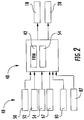
FIG. 2 is a block diagram illustrating a control system having a rotor moment control system, in accordance with an exemplary embodiment; -
FIG. 3 is a block diagram illustrating the rotor moment control architecture across a system of hardware and software components, in accordance with an aspect of an exemplary embodiment; and -
FIG 4 depicts a block diagram describing a control algorithm which each flight control computer (FCC) of the rotor moment control architecture ofFIG. 3 . - A detailed description of one or more embodiments of the disclosed apparatus and method are presented herein by way of exemplification and not limitation with reference to the Figures.
-
FIG. 1 schematically illustrates arotary wing aircraft 10 having amain rotor assembly 12. Theaircraft 10 includes anairframe 14 having anose 15 an extendingtail 16 which mounts atail rotor assembly 18, such as an anti-torque system, a translational thrust system, a pusher propeller, a rotor propulsion system, and the like. Themain rotor assembly 12 is driven about an axis of rotation R through a gearbox (illustrated schematically at 20) by one ormore engines 22.Main rotor assembly 12 includes a plurality of rotor blades, one of which is indicated at 24, mounted to arotor hub 26. Aswashplate 28 provides control movements torotor blades 24. More specifically,swashplate 28 is activated to affect a state or orientation of therotor blades 24. Although a particular helicopter configuration is illustrated and described in the disclosed embodiment, other configurations and/or machines, such as high speed compound rotary wing aircraft with supplemental translational thrust systems, dual contra-rotating, or co-rotating coaxial rotor system aircraft, tilt-rotors and tilt-wing aircraft, may also benefit from the exemplary embodiments. -
Rotary wing aircraft 10 includes acontrol system 40, illustrated inFIG. 2 , which employs fly-by-wire (FBW) controls 42 that provide inputs toswashplate 28 and/ortail rotor assembly 18. A plurality ofcontrol inceptor devices 48 including a cyclic incepter 50, acollective inceptor 52 andpedals 54 provide input tocontrol system 40. The commands provided bycontrol inceptor devices 48 throughcontrol system 40 depend on an operational mode ofrotary wing aircraft 10. - One operational mode of
control system 40 is a proportional ground control mode. In the ground control mode, cyclic 50 may be employed to change a pitch angle of therotor blades 24 in a cyclical fashion to effectively tiltswashplate 28 in a particular direction, resulting in movement ofrotary wing aircraft 10. In the same mode,collective inceptor 52 changes a pitch angle of therotor blades 24 collectively, resulting in an increase or decrease in total lift derived frommain rotor assembly 12. Pedals 54 serve to controltail rotor 18 to adjust yaw or a direction ofnose 15. The proportional ground control mode provides a change in a position of a flight control surface (not separately labeled) ofrotary wing aircraft 10 in direct proportion to a movement of one or more ofcontrol inceptor devices 48. For example, a position or orientation ofswashplate 28 is in direct proportion to a position of cyclic inceptor 50. - Another operational mode of the control system is a model following control or flight mode. In the flight mode,
control system 40 receives one or more pilot inputs, performs various calculations on the one or more received inputs using an inverse model ofrotary wing aircraft 10, and then moves a corresponding flight control surface to a determined position. Often times, both of these flight control operational modes are employed by a pilot during aircraft operations. Transitioning from the proportional ground control mode to the model following control mode can sometimes cause an unwanted transients, particularly in high wind conditions. -
Control inceptors devices 48 perform different functions depending on the particular operational mode. For example, in order to maintainswashplate 28 in a particular non-centered configuration in the proportional ground control mode,cyclic inceptor 52 held out of a detent or centered position. However, in the flight mode, commands received fromcontrol inceptor devices 48 command an aircraft state, rather than a position ofswashplate 28. Further, theflight mode swashplate 28 may be commanded to a non-centered position by thecontrol system 40, even while a unique trim inceptor is in detent. More specifically,cyclic inceptor 52 remains in the detent position unless a change is desired in the aircraft state (rates, attitudes, positions, velocities, etc.). To affect a desired change, the pilot moves cyclic inceptor 50 out of the detent position. - In accordance with an aspect of an exemplary embodiment,
control system 40 includes a rotormoment control system 64 that selectively operates one or more control surfaces (not separately labeled) onrotor blades 24 to counter-act external forces onrotary wing aircraft 10 when transitioning from the proportional ground control mode to the model following controls or flight mode. For example, rotormoment control system 64 may selectively activate the one or more control surfaces to counter-act wind forces acting onrotary wing aircraft 10. - As will be detailed more fully below, rotor
moment control system 64 receives inputs from a rotor moment sensor system 67 that includes one or morerotor moment sensors Rotor moment sensor 70 may be mounted to a rotor shaft (not separately labeled),rotor moment sensor 71 may be mounted to a rotor hub arm (also not separately labeled) androtor moment sensor 72 may be mounted to one or more ofrotor blades 24. Rotor moment sensors 70-72 may take on a variety of forms including fiber optic strain gauges, laser displacement sensors that measure blade flap/lag bending and movement, electrical strain gauges, accelerometers and the like. Further, it should be understood that the number and location of rotor moment sensors may vary. - Rotor
moment control system 64 may also receive input from an aircraft conditionparameter sensor system 80. Aircraft conditionparameter sensor system 80 may include a first weight-on-wheels (WOW)sensor 82, asecond WOW sensor 83, and athird WOW sensor 84.First WOW sensor 82 may be associated with a forward landing gear (not separately labeled).Second WOW sensor 83 may be associated with an aft landing gear (also not separately labeled) andthird WOW sensor 84 may constitute a tire pressure sensor.WOW sensors aircraft 10 is resting on the ground. WhenWOW sensors rotary wing aircraft 10 is transitioning from the proportional ground control mode to the model following controls or flight mode. WOW sensors 82-84 may take a variety of forms including strut mounted strain gauges, axle mounted strain gauges, tire pressure sensors, inertial movement sensors, solid state switches and the like. The number and location of rotor moment sensors and WOW sensors may vary. Rotormoment control system 64 may also receive cyclic position reference inputs from a cyclicposition reference sensor 87. - In accordance with an exemplary embodiment illustrated in
FIG. 3 , rotormoment control system 64 includes a first flight control computer (FCC) 90, asecond FCC 92, and athird FCC 94. Each FCC includes one or more processors that cooperate to establish rotor blade control surface positions that avoid system transients as will be detailed below. At this point, it should be understood that the number and location of FCC's inrotary wing aircraft 10 may vary. - First FCC is operatively connected with
rotor moment sensor 70 andWOW sensor 82.Rotor moment sensor 70 andWOW sensor 82 are also operatively connected withthird FCC 94.Second FCC 92 is operatively connected withrotor moment sensor 71,WOW sensor 83 and cyclicposition reference sensor 87.Third FCC 94 is operatively connected withrotor moment sensor 72, andWOW sensor 84. As will be detailed more fully below, first, second, andthird FCCs rotary wing aircraft 10 when transitioning from the proportional ground control mode to the model following controls or flight mode. - Reference will now follow to
FIG. 4 in describingFCC 92 with an understanding thatFCC 90 andFCC 94 may include similar components having similar functions.FCC 92 includes a rotormoment check module 120, anincepter check module 122 and aWOW check module 123. Rotormoment check module 120 verifies rotor moment signals received from, for example,rotor moment sensor 71.Incepter check module 122 validates signals received from cyclic incepter 50, andWOW check module 123 verifies signals received from, for example,WOW sensor 83.FCC 92 also includes a plurality of cross voting or crossverification modules Cross verification module 130 verifies rotor moment signals received from first andthird FCCs Cross verification module 132 verifies cyclic inceptor signals received from first andthird FCCs verification module 132 verifies WOW signals received from first andthird FCCs - In accordance with an aspect of an exemplary embodiment,
FCC 92 includes afilter 140 operatively connected to crossverification module 130. Filter 140 passes filtered rotor moment signals to afirst summer 150.FCC 92 further includes aswitch 152 operatively connected to crossverification module 130, and through amode control module 154 to cross verification module 134.Mode control module 154 is configured to control ground modes.Switch 152 is operatively connected to acommand shaping module 160 which, in turn, is operatively connected to asystem delay 162 that is coupled tofirst summer 150. - In further accordance with an exemplary embodiment,
FCC 92 includes afeedback gain module 170 operatively connected tofirst summer 150.Feedback gain module 170 sends a first feedback gain signal to asecond summer 180 and a second feedback gain signal to atrim integrator 182 which provides an integral trim command tosecond summer 180.FCC 92 also includes a momentinverse module 184 operatively connected betweencommand shaping module 160 andsecond summer 180.Moment inverse module 184 provides feedforward commands tosecond summer 180. - In accordance with an aspect of an exemplary embodiment,
second summer 180 combines signals fromfeedback gain module 170,trim integrator module 182 and momentinverse module 184. A combined signal is then passed to a mixing andfiltering module 190 which substantially eliminates cross-coupling. A trim control signal is then passed torotor blades 24. In this manner, rotormoment control system 64 may establish a wind compensated neutral for cyclic incepter 50 and dampens system transients forrotor blades 24 whenrotary wing aircraft 10 transitions from the proportional ground control mode to the model following controls or flight mode. - The term "about" is intended to include the degree of error associated with measurement of the particular quantity based upon the equipment available at the time of filing the application. For example, "about" can include a range of ± 8% or 5%, or 2% of a given value.
- The terminology used herein is for the purpose of describing particular embodiments only and is not intended to be limiting of the present disclosure. As used herein, the singular forms "a", "an" and "the" are intended to include the plural forms as well, unless the context clearly indicates otherwise. It will be further understood that the terms "comprises" and/or "comprising," when used in this specification, specify the presence of stated features, integers, steps, operations, elements, and/or components, but do not preclude the presence or addition of one or more other features, integers, steps, operations, element components, and/or groups thereof.
- While the present disclosure has been described with reference to an exemplary embodiment or embodiments, it will be understood by those skilled in the art that various changes may be made without departing from the scope of the present disclosure. In addition, many modifications may be made to adapt a particular situation or material to the teachings of the present disclosure without departing from the essential scope thereof. Therefore, it is intended that the present disclosure not be limited to the particular embodiment disclosed as the best mode contemplated for carrying out this present disclosure, but that the present disclosure will include all embodiments falling within the scope of the claims.
Claims (14)
- A method of controlling rotor moments in a rotor moment control system (64) for a rotary wing aircraft (10) configured to analyze rotor moments and reduce rotary wing aircraft transients during a transition from a proportional ground control mode and a model following controls or flight mode, the method comprising:receiving, in a flight control computer (FCC), a rotor moment reference value based on pilot inceptor inputs;sensing rotor moment which includes receiving signals from at least one sensor (70, 71, 72) mounted to one of a rotor shaft, a rotor hub arm, and along a span of a rotor blade;receiving, in the FCC, a rotary wing aircraft condition parameter; andestablishing, through the FCC, a rotor blade pitch angle for one or more of a plurality of rotor blades that counteracts external forces acting upon the rotary wing aircraft (10) when transitioning from the proportional ground control mode to the model following controls or flight mode.
- The method of claim 1, wherein receiving the rotor moment reference value includes receiving a cyclic inceptor position.
- The method of claim 1 or 2, wherein receiving the rotary wing aircraft condition parameter includes receiving signals from one or more weight-on-wheels sensors (82, 83, 84).
- The method of claim 3, wherein receiving signals from one or more weight-on-wheels sensors (82, 83, 84) includes detecting a transition from a proportional ground control mode to a model following controls or flight mode.
- The method of one of the claims 1 to 4, wherein establishing, through the FCC, the rotor blade pitch angle includes comparing rotor moment inputs from at least two flight control computers (90, 92, 94).
- The method of one of the claims 1 to 5, wherein establishing, through the FCC, the rotor blade pitch angle includes determining a rotor moment error and providing rotor moment feedback commands to one or more rotor blades.
- The method of one of the claims 1 to 6, wherein establishing, through the FCC, the rotor blade pitch angle includes determining a rotor moment error and providing rotor moment feed forward commands to one or more rotor blades
- The method of one of the claims 1 to 7, wherein establishing, through the FCC, the rotor blade pitch angle includes combining rotor moment feedback commands and rotor moment feed forward commands to one or more rotor blades.
- A rotor moment control system (64) for a rotary wing aircraft (10) comprising:a flight control computer (FCC);the rotor moment control system (64) configured to analyze rotor moments and reduce rotary wing aircraft transients during a transition from a proportional ground control mode and a model following controls or flight mode, the rotor moment control system (64) including computer readable program code embodied therewith, the computer readable program code, when executed by the FCC, causes the FCC to:receive a rotor moment reference value based on pilot inceptor inputs;sense rotor moment which includes receiving signals from at least one sensor (70, 71, 72) mounted to one of a rotor shaft, a rotor hub arm, and along a span of a rotor blade;receive a rotary wing aircraft condition parameter; andestablish a rotor blade pitch angle for one or more of a plurality of rotor blades that counteracts external forces acting upon the rotary wing aircraft.
- The system of claim 9, wherein the computer readable program code, when executed by the FCC, causes the FCC to: receive a cyclic position when receiving the rotor moment reference value includes receiving a cyclic inceptor position.
- The system of claim 9 or 10, wherein the computer readable program code, when executed by the FCC, causes the FCC to: receive signals from one or more weight-on-wheels sensors (82, 83, 84) indicating a transition from a proportional ground control mode to a model following controls mode when receiving the rotary wing aircraft condition parameter.
- The system of one of the claims 9 to 11, wherein establishing, through the processor, the rotor blade pitch angle includes comparing rotor moment inputs from at least two flight control computers.
- The system of one of the claims 9 to 12, wherein the computer readable program code, when executed by the FCC, causes the FCC to: determine a rotor moment error and provide rotor moment feedback commands to one or more rotor blades when establishing the rotor blade pitch angle.
- The system of one of the claims 9 to 13, wherein the computer readable program code, when executed by the FCC, causes the FCC to: combining rotor moment feedback commands and rotor moment feed forward commands to one or more rotor blades when establishing the rotor blade pitch angle.
Applications Claiming Priority (1)
| Application Number | Priority Date | Filing Date | Title |
|---|---|---|---|
| US201662297631P | 2016-02-19 | 2016-02-19 |
Publications (2)
| Publication Number | Publication Date |
|---|---|
| EP3208190A1 EP3208190A1 (en) | 2017-08-23 |
| EP3208190B1 true EP3208190B1 (en) | 2019-06-12 |
Family
ID=58057031
Family Applications (1)
| Application Number | Title | Priority Date | Filing Date |
|---|---|---|---|
| EP17156675.5A Active EP3208190B1 (en) | 2016-02-19 | 2017-02-17 | Rotor moment control system for a rotary wing aircraft |
Country Status (2)
| Country | Link |
|---|---|
| US (1) | US10809744B2 (en) |
| EP (1) | EP3208190B1 (en) |
Families Citing this family (8)
| Publication number | Priority date | Publication date | Assignee | Title |
|---|---|---|---|---|
| US9908616B1 (en) * | 2017-05-12 | 2018-03-06 | Kitty Hawk Corporation | Geometry-based flight control system |
| US10766613B2 (en) | 2017-11-28 | 2020-09-08 | Textron Innovations Inc. | System and method for rotorcraft-weight-on-wheels flight state transition control |
| US10654560B2 (en) | 2018-01-25 | 2020-05-19 | Textron Innovations Inc. | Control surface transitioning for hybrid VTOL aircraft |
| US11427314B2 (en) * | 2018-05-15 | 2022-08-30 | Textron Innovations Inc. | Control systems and methods for rotating systems |
| CN110884678B (en) * | 2019-12-04 | 2023-05-26 | 中国直升机设计研究所 | Displacement sensor arrangement method for fly-by-wire control system of helicopter |
| CN112486218B (en) * | 2020-12-01 | 2022-12-06 | 深圳联合飞机科技有限公司 | Helicopter control method and system |
| US11561558B1 (en) | 2021-10-30 | 2023-01-24 | Beta Air, Llc | Systems and methods for wind compensation of an electric aircraft |
| US20230098878A1 (en) * | 2021-09-29 | 2023-03-30 | Lockheed Martin Corporation | Landing gear feedback control system for an aircraft |
Family Cites Families (15)
| Publication number | Priority date | Publication date | Assignee | Title |
|---|---|---|---|---|
| US6648269B2 (en) | 2001-12-10 | 2003-11-18 | Sikorsky Aircraft Corporation | Trim augmentation system for a rotary wing aircraft |
| JP4300010B2 (en) * | 2002-10-08 | 2009-07-22 | 富士重工業株式会社 | Unmanned helicopter, unmanned helicopter takeoff method and unmanned helicopter landing method |
| US7930074B2 (en) | 2007-03-19 | 2011-04-19 | Sikorsky Aircraft Corporation | Vertical speed and flight path command module for displacement collective utilizing tactile cueing and tactile feedback |
| US8527247B1 (en) | 2008-03-20 | 2013-09-03 | Sandia Corporation | Nonlinear power flow feedback control for improved stability and performance of airfoil sections |
| US7873445B2 (en) * | 2007-03-26 | 2011-01-18 | Bell Helicopter Textron, Inc. | Governor for a rotor with a variable maximum collective pitch |
| US7970498B2 (en) | 2007-06-01 | 2011-06-28 | Sikorsky Aircraft Corporation | Model based sensor system for loads aware control laws |
| EP2261116B1 (en) | 2009-06-09 | 2019-05-22 | Sikorsky Aircraft Corporation | Automatic trim system for fly-by-wire aircraft with unique trim controllers |
| US10086932B2 (en) * | 2011-01-14 | 2018-10-02 | Sikorsky Aircraft Corporation | Moment limiting control laws for dual rigid rotor helicopters |
| US9317041B2 (en) * | 2014-01-21 | 2016-04-19 | Sikorsky Aircraft Corporation | Rotor moment feedback for stability augmentation |
| EP3126231B1 (en) | 2014-04-02 | 2019-01-02 | Sikorsky Aircraft Corporation | Elevator load alleviating control for a rotary wing aircraft |
| EP2940547B1 (en) * | 2014-05-01 | 2019-03-06 | Sikorsky Aircraft Corporation | Coaxial rotor low-speed mixing |
| WO2016011099A1 (en) * | 2014-07-18 | 2016-01-21 | Sikorsky Aircraft Corporation | System for determining weight-on-wheels using lidar |
| WO2016048437A1 (en) * | 2014-09-23 | 2016-03-31 | Sikorsky Aircraft Corporation | Initial rotor state compensation for a rotorcraft |
| WO2016053408A1 (en) * | 2014-10-01 | 2016-04-07 | Sikorsky Aircraft Corporation | Acoustic signature variation of aircraft utilizing a clutch |
| WO2016167865A1 (en) * | 2015-04-16 | 2016-10-20 | Sikorsky Aircraft Corporation | Gust alleviating control for a coaxial rotary wing aircraft |
-
2017
- 2017-02-06 US US15/425,634 patent/US10809744B2/en active Active
- 2017-02-17 EP EP17156675.5A patent/EP3208190B1/en active Active
Non-Patent Citations (1)
| Title |
|---|
| None * |
Also Published As
| Publication number | Publication date |
|---|---|
| US20180004229A1 (en) | 2018-01-04 |
| EP3208190A1 (en) | 2017-08-23 |
| US10809744B2 (en) | 2020-10-20 |
Similar Documents
| Publication | Publication Date | Title |
|---|---|---|
| EP3208190B1 (en) | Rotor moment control system for a rotary wing aircraft | |
| EP2476614B1 (en) | Moment limiting control laws for dual rigid rotor helicopters | |
| EP3445652B1 (en) | Combined pitch and forward thrust control for unmanned aircraft systems | |
| EP2261116B1 (en) | Automatic trim system for fly-by-wire aircraft with unique trim controllers | |
| AU2017252251B2 (en) | Wind finding and compensation for unmanned aircraft systems | |
| US10124889B2 (en) | Tail rotor failure recovery controller | |
| CN110127041B (en) | System and method for rotorcraft spin-entry assist | |
| EP2168022B1 (en) | Model based sensor system for loads aware control laws | |
| US8002220B2 (en) | Rate limited active pilot inceptor system and method | |
| CN108502196A (en) | Reversed tactile cue for rotor craft rotor overspeed protection | |
| CN110498054B (en) | Systems and methods for haptic cues using variable friction and force gradients | |
| EP3882734B1 (en) | Method for protection against vortex ring state and associated device | |
| EP3590830B1 (en) | Method and apparatus for proximity control between rotating and non-rotating aircraft components | |
| EP3326911B1 (en) | Rotor speed control using a feed-forward rotor speed command | |
| US11396363B2 (en) | Open and closed control of actuators, which drive aerodynamic control surfaces of an aircraft | |
| EP3225544B1 (en) | Touchdown orientation control system for a rotary wing aircraft and method | |
| US20230098878A1 (en) | Landing gear feedback control system for an aircraft | |
| US9926076B2 (en) | Acceleration smoothing holding overall kinetic energy control | |
| CN111392036A (en) | System and method for controlling a rotorcraft | |
| US10618635B2 (en) | Pilot activated trim for fly-by-wire aircraft | |
| US20230101964A1 (en) | Method for hovering an aircraft with respect to an axis with a controllable pitch angle | |
| US20240010326A1 (en) | Vehicle based optimization system and method therefor |
Legal Events
| Date | Code | Title | Description |
|---|---|---|---|
| PUAI | Public reference made under article 153(3) epc to a published international application that has entered the european phase |
Free format text: ORIGINAL CODE: 0009012 |
|
| STAA | Information on the status of an ep patent application or granted ep patent |
Free format text: STATUS: THE APPLICATION HAS BEEN PUBLISHED |
|
| AK | Designated contracting states |
Kind code of ref document: A1 Designated state(s): AL AT BE BG CH CY CZ DE DK EE ES FI FR GB GR HR HU IE IS IT LI LT LU LV MC MK MT NL NO PL PT RO RS SE SI SK SM TR |
|
| AX | Request for extension of the european patent |
Extension state: BA ME |
|
| STAA | Information on the status of an ep patent application or granted ep patent |
Free format text: STATUS: REQUEST FOR EXAMINATION WAS MADE |
|
| 17P | Request for examination filed |
Effective date: 20180220 |
|
| RBV | Designated contracting states (corrected) |
Designated state(s): AL AT BE BG CH CY CZ DE DK EE ES FI FR GB GR HR HU IE IS IT LI LT LU LV MC MK MT NL NO PL PT RO RS SE SI SK SM TR |
|
| GRAP | Despatch of communication of intention to grant a patent |
Free format text: ORIGINAL CODE: EPIDOSNIGR1 |
|
| STAA | Information on the status of an ep patent application or granted ep patent |
Free format text: STATUS: GRANT OF PATENT IS INTENDED |
|
| INTG | Intention to grant announced |
Effective date: 20190110 |
|
| GRAS | Grant fee paid |
Free format text: ORIGINAL CODE: EPIDOSNIGR3 |
|
| GRAA | (expected) grant |
Free format text: ORIGINAL CODE: 0009210 |
|
| STAA | Information on the status of an ep patent application or granted ep patent |
Free format text: STATUS: THE PATENT HAS BEEN GRANTED |
|
| AK | Designated contracting states |
Kind code of ref document: B1 Designated state(s): AL AT BE BG CH CY CZ DE DK EE ES FI FR GB GR HR HU IE IS IT LI LT LU LV MC MK MT NL NO PL PT RO RS SE SI SK SM TR |
|
| REG | Reference to a national code |
Ref country code: GB Ref legal event code: FG4D |
|
| REG | Reference to a national code |
Ref country code: CH Ref legal event code: EP |
|
| REG | Reference to a national code |
Ref country code: AT Ref legal event code: REF Ref document number: 1142220 Country of ref document: AT Kind code of ref document: T Effective date: 20190615 |
|
| REG | Reference to a national code |
Ref country code: DE Ref legal event code: R096 Ref document number: 602017004366 Country of ref document: DE |
|
| REG | Reference to a national code |
Ref country code: IE Ref legal event code: FG4D |
|
| REG | Reference to a national code |
Ref country code: NL Ref legal event code: MP Effective date: 20190612 |
|
| REG | Reference to a national code |
Ref country code: LT Ref legal event code: MG4D |
|
| PG25 | Lapsed in a contracting state [announced via postgrant information from national office to epo] |
Ref country code: SE Free format text: LAPSE BECAUSE OF FAILURE TO SUBMIT A TRANSLATION OF THE DESCRIPTION OR TO PAY THE FEE WITHIN THE PRESCRIBED TIME-LIMIT Effective date: 20190612 Ref country code: AL Free format text: LAPSE BECAUSE OF FAILURE TO SUBMIT A TRANSLATION OF THE DESCRIPTION OR TO PAY THE FEE WITHIN THE PRESCRIBED TIME-LIMIT Effective date: 20190612 Ref country code: LT Free format text: LAPSE BECAUSE OF FAILURE TO SUBMIT A TRANSLATION OF THE DESCRIPTION OR TO PAY THE FEE WITHIN THE PRESCRIBED TIME-LIMIT Effective date: 20190612 Ref country code: HR Free format text: LAPSE BECAUSE OF FAILURE TO SUBMIT A TRANSLATION OF THE DESCRIPTION OR TO PAY THE FEE WITHIN THE PRESCRIBED TIME-LIMIT Effective date: 20190612 Ref country code: NO Free format text: LAPSE BECAUSE OF FAILURE TO SUBMIT A TRANSLATION OF THE DESCRIPTION OR TO PAY THE FEE WITHIN THE PRESCRIBED TIME-LIMIT Effective date: 20190912 Ref country code: FI Free format text: LAPSE BECAUSE OF FAILURE TO SUBMIT A TRANSLATION OF THE DESCRIPTION OR TO PAY THE FEE WITHIN THE PRESCRIBED TIME-LIMIT Effective date: 20190612 |
|
| PG25 | Lapsed in a contracting state [announced via postgrant information from national office to epo] |
Ref country code: GR Free format text: LAPSE BECAUSE OF FAILURE TO SUBMIT A TRANSLATION OF THE DESCRIPTION OR TO PAY THE FEE WITHIN THE PRESCRIBED TIME-LIMIT Effective date: 20190913 Ref country code: BG Free format text: LAPSE BECAUSE OF FAILURE TO SUBMIT A TRANSLATION OF THE DESCRIPTION OR TO PAY THE FEE WITHIN THE PRESCRIBED TIME-LIMIT Effective date: 20190912 Ref country code: LV Free format text: LAPSE BECAUSE OF FAILURE TO SUBMIT A TRANSLATION OF THE DESCRIPTION OR TO PAY THE FEE WITHIN THE PRESCRIBED TIME-LIMIT Effective date: 20190612 Ref country code: RS Free format text: LAPSE BECAUSE OF FAILURE TO SUBMIT A TRANSLATION OF THE DESCRIPTION OR TO PAY THE FEE WITHIN THE PRESCRIBED TIME-LIMIT Effective date: 20190612 |
|
| REG | Reference to a national code |
Ref country code: AT Ref legal event code: MK05 Ref document number: 1142220 Country of ref document: AT Kind code of ref document: T Effective date: 20190612 |
|
| PG25 | Lapsed in a contracting state [announced via postgrant information from national office to epo] |
Ref country code: AT Free format text: LAPSE BECAUSE OF FAILURE TO SUBMIT A TRANSLATION OF THE DESCRIPTION OR TO PAY THE FEE WITHIN THE PRESCRIBED TIME-LIMIT Effective date: 20190612 Ref country code: PT Free format text: LAPSE BECAUSE OF FAILURE TO SUBMIT A TRANSLATION OF THE DESCRIPTION OR TO PAY THE FEE WITHIN THE PRESCRIBED TIME-LIMIT Effective date: 20191014 Ref country code: SK Free format text: LAPSE BECAUSE OF FAILURE TO SUBMIT A TRANSLATION OF THE DESCRIPTION OR TO PAY THE FEE WITHIN THE PRESCRIBED TIME-LIMIT Effective date: 20190612 Ref country code: EE Free format text: LAPSE BECAUSE OF FAILURE TO SUBMIT A TRANSLATION OF THE DESCRIPTION OR TO PAY THE FEE WITHIN THE PRESCRIBED TIME-LIMIT Effective date: 20190612 Ref country code: CZ Free format text: LAPSE BECAUSE OF FAILURE TO SUBMIT A TRANSLATION OF THE DESCRIPTION OR TO PAY THE FEE WITHIN THE PRESCRIBED TIME-LIMIT Effective date: 20190612 Ref country code: NL Free format text: LAPSE BECAUSE OF FAILURE TO SUBMIT A TRANSLATION OF THE DESCRIPTION OR TO PAY THE FEE WITHIN THE PRESCRIBED TIME-LIMIT Effective date: 20190612 Ref country code: RO Free format text: LAPSE BECAUSE OF FAILURE TO SUBMIT A TRANSLATION OF THE DESCRIPTION OR TO PAY THE FEE WITHIN THE PRESCRIBED TIME-LIMIT Effective date: 20190612 |
|
| PG25 | Lapsed in a contracting state [announced via postgrant information from national office to epo] |
Ref country code: IT Free format text: LAPSE BECAUSE OF FAILURE TO SUBMIT A TRANSLATION OF THE DESCRIPTION OR TO PAY THE FEE WITHIN THE PRESCRIBED TIME-LIMIT Effective date: 20190612 Ref country code: IS Free format text: LAPSE BECAUSE OF FAILURE TO SUBMIT A TRANSLATION OF THE DESCRIPTION OR TO PAY THE FEE WITHIN THE PRESCRIBED TIME-LIMIT Effective date: 20191012 Ref country code: SM Free format text: LAPSE BECAUSE OF FAILURE TO SUBMIT A TRANSLATION OF THE DESCRIPTION OR TO PAY THE FEE WITHIN THE PRESCRIBED TIME-LIMIT Effective date: 20190612 |
|
| REG | Reference to a national code |
Ref country code: DE Ref legal event code: R097 Ref document number: 602017004366 Country of ref document: DE |
|
| PG25 | Lapsed in a contracting state [announced via postgrant information from national office to epo] |
Ref country code: TR Free format text: LAPSE BECAUSE OF FAILURE TO SUBMIT A TRANSLATION OF THE DESCRIPTION OR TO PAY THE FEE WITHIN THE PRESCRIBED TIME-LIMIT Effective date: 20190612 |
|
| PLBE | No opposition filed within time limit |
Free format text: ORIGINAL CODE: 0009261 |
|
| STAA | Information on the status of an ep patent application or granted ep patent |
Free format text: STATUS: NO OPPOSITION FILED WITHIN TIME LIMIT |
|
| PG25 | Lapsed in a contracting state [announced via postgrant information from national office to epo] |
Ref country code: PL Free format text: LAPSE BECAUSE OF FAILURE TO SUBMIT A TRANSLATION OF THE DESCRIPTION OR TO PAY THE FEE WITHIN THE PRESCRIBED TIME-LIMIT Effective date: 20190612 Ref country code: DK Free format text: LAPSE BECAUSE OF FAILURE TO SUBMIT A TRANSLATION OF THE DESCRIPTION OR TO PAY THE FEE WITHIN THE PRESCRIBED TIME-LIMIT Effective date: 20190612 |
|
| 26N | No opposition filed |
Effective date: 20200313 |
|
| PG25 | Lapsed in a contracting state [announced via postgrant information from national office to epo] |
Ref country code: IS Free format text: LAPSE BECAUSE OF FAILURE TO SUBMIT A TRANSLATION OF THE DESCRIPTION OR TO PAY THE FEE WITHIN THE PRESCRIBED TIME-LIMIT Effective date: 20200224 Ref country code: SI Free format text: LAPSE BECAUSE OF FAILURE TO SUBMIT A TRANSLATION OF THE DESCRIPTION OR TO PAY THE FEE WITHIN THE PRESCRIBED TIME-LIMIT Effective date: 20190612 |
|
| PG2D | Information on lapse in contracting state deleted |
Ref country code: IS |
|
| REG | Reference to a national code |
Ref country code: CH Ref legal event code: PL |
|
| REG | Reference to a national code |
Ref country code: BE Ref legal event code: MM Effective date: 20200229 |
|
| PG25 | Lapsed in a contracting state [announced via postgrant information from national office to epo] |
Ref country code: ES Free format text: LAPSE BECAUSE OF FAILURE TO SUBMIT A TRANSLATION OF THE DESCRIPTION OR TO PAY THE FEE WITHIN THE PRESCRIBED TIME-LIMIT Effective date: 20190612 Ref country code: MC Free format text: LAPSE BECAUSE OF FAILURE TO SUBMIT A TRANSLATION OF THE DESCRIPTION OR TO PAY THE FEE WITHIN THE PRESCRIBED TIME-LIMIT Effective date: 20190612 Ref country code: LU Free format text: LAPSE BECAUSE OF NON-PAYMENT OF DUE FEES Effective date: 20200217 |
|
| PG25 | Lapsed in a contracting state [announced via postgrant information from national office to epo] |
Ref country code: CH Free format text: LAPSE BECAUSE OF NON-PAYMENT OF DUE FEES Effective date: 20200229 Ref country code: LI Free format text: LAPSE BECAUSE OF NON-PAYMENT OF DUE FEES Effective date: 20200229 |
|
| PG25 | Lapsed in a contracting state [announced via postgrant information from national office to epo] |
Ref country code: IE Free format text: LAPSE BECAUSE OF NON-PAYMENT OF DUE FEES Effective date: 20200217 |
|
| PG25 | Lapsed in a contracting state [announced via postgrant information from national office to epo] |
Ref country code: BE Free format text: LAPSE BECAUSE OF NON-PAYMENT OF DUE FEES Effective date: 20200229 |
|
| PG25 | Lapsed in a contracting state [announced via postgrant information from national office to epo] |
Ref country code: MT Free format text: LAPSE BECAUSE OF FAILURE TO SUBMIT A TRANSLATION OF THE DESCRIPTION OR TO PAY THE FEE WITHIN THE PRESCRIBED TIME-LIMIT Effective date: 20190612 Ref country code: CY Free format text: LAPSE BECAUSE OF FAILURE TO SUBMIT A TRANSLATION OF THE DESCRIPTION OR TO PAY THE FEE WITHIN THE PRESCRIBED TIME-LIMIT Effective date: 20190612 |
|
| PG25 | Lapsed in a contracting state [announced via postgrant information from national office to epo] |
Ref country code: MK Free format text: LAPSE BECAUSE OF FAILURE TO SUBMIT A TRANSLATION OF THE DESCRIPTION OR TO PAY THE FEE WITHIN THE PRESCRIBED TIME-LIMIT Effective date: 20190612 |
|
| PGFP | Annual fee paid to national office [announced via postgrant information from national office to epo] |
Ref country code: FR Payment date: 20230223 Year of fee payment: 7 |
|
| PGFP | Annual fee paid to national office [announced via postgrant information from national office to epo] |
Ref country code: GB Payment date: 20230227 Year of fee payment: 7 Ref country code: DE Payment date: 20230223 Year of fee payment: 7 |
|
| P01 | Opt-out of the competence of the unified patent court (upc) registered |
Effective date: 20230523 |