EP3207970B1 - A filling container - Google Patents
A filling container Download PDFInfo
- Publication number
- EP3207970B1 EP3207970B1 EP17151714.7A EP17151714A EP3207970B1 EP 3207970 B1 EP3207970 B1 EP 3207970B1 EP 17151714 A EP17151714 A EP 17151714A EP 3207970 B1 EP3207970 B1 EP 3207970B1
- Authority
- EP
- European Patent Office
- Prior art keywords
- tubes
- hollow tubes
- connector
- hoop
- rubber sleeve
- Prior art date
- Legal status (The legal status is an assumption and is not a legal conclusion. Google has not performed a legal analysis and makes no representation as to the accuracy of the status listed.)
- Active
Links
- 239000003292 glue Substances 0.000 claims 1
- XLYOFNOQVPJJNP-UHFFFAOYSA-N water Substances O XLYOFNOQVPJJNP-UHFFFAOYSA-N 0.000 description 22
- 238000007789 sealing Methods 0.000 description 14
- 238000001914 filtration Methods 0.000 description 10
- 239000007788 liquid Substances 0.000 description 10
- 238000010586 diagram Methods 0.000 description 6
- 238000000034 method Methods 0.000 description 4
- 239000008280 blood Substances 0.000 description 3
- 210000004369 blood Anatomy 0.000 description 3
- 210000002700 urine Anatomy 0.000 description 3
- 239000004568 cement Substances 0.000 description 2
- 230000000694 effects Effects 0.000 description 2
- 241001465754 Metazoa Species 0.000 description 1
- 238000009434 installation Methods 0.000 description 1
- 230000002093 peripheral effect Effects 0.000 description 1
Images


Classifications
-
- A—HUMAN NECESSITIES
- A63—SPORTS; GAMES; AMUSEMENTS
- A63H—TOYS, e.g. TOPS, DOLLS, HOOPS OR BUILDING BLOCKS
- A63H27/00—Toy aircraft; Other flying toys
- A63H27/10—Balloons
-
- A—HUMAN NECESSITIES
- A61—MEDICAL OR VETERINARY SCIENCE; HYGIENE
- A61B—DIAGNOSIS; SURGERY; IDENTIFICATION
- A61B5/00—Measuring for diagnostic purposes; Identification of persons
- A61B5/15—Devices for taking samples of blood
- A61B5/150007—Details
- A61B5/150015—Source of blood
- A61B5/15003—Source of blood for venous or arterial blood
-
- A—HUMAN NECESSITIES
- A61—MEDICAL OR VETERINARY SCIENCE; HYGIENE
- A61B—DIAGNOSIS; SURGERY; IDENTIFICATION
- A61B5/00—Measuring for diagnostic purposes; Identification of persons
- A61B5/15—Devices for taking samples of blood
- A61B5/150007—Details
- A61B5/150343—Collection vessels for collecting blood samples from the skin surface, e.g. test tubes, cuvettes
-
- A—HUMAN NECESSITIES
- A61—MEDICAL OR VETERINARY SCIENCE; HYGIENE
- A61B—DIAGNOSIS; SURGERY; IDENTIFICATION
- A61B5/00—Measuring for diagnostic purposes; Identification of persons
- A61B5/15—Devices for taking samples of blood
- A61B5/155—Devices specially adapted for continuous or multiple sampling, e.g. at predetermined intervals
-
- A—HUMAN NECESSITIES
- A61—MEDICAL OR VETERINARY SCIENCE; HYGIENE
- A61B—DIAGNOSIS; SURGERY; IDENTIFICATION
- A61B10/00—Other methods or instruments for diagnosis, e.g. instruments for taking a cell sample, for biopsy, for vaccination diagnosis; Sex determination; Ovulation-period determination; Throat striking implements
- A61B10/0045—Devices for taking samples of body liquids
- A61B10/007—Devices for taking samples of body liquids for taking urine samples
-
- A—HUMAN NECESSITIES
- A63—SPORTS; GAMES; AMUSEMENTS
- A63H—TOYS, e.g. TOPS, DOLLS, HOOPS OR BUILDING BLOCKS
- A63H27/00—Toy aircraft; Other flying toys
- A63H27/10—Balloons
- A63H2027/1033—Inflation devices or methods for inflating balloons
Definitions
- the current invention is related to the technical field of canned equipments, especially a new type of filling container.
- US 9051066 discloses a liquid filling container system and method.
- the system contains an opening at one side, and a shell body with several holes at the other side.
- the top parts of the hollow tubes correspond with each of the several holes respectively.
- the bottom parts of the hollow tubes are connected with a removable container.
- CN 204293867 discloses a water ball filling device which comprises a sleeve pipe, balloons and water pipes.
- a water outlet in the lower end of the sleeve pipe is connected with the thin long water pipes.
- the tail ends of the water pipes are connected with the balloons. Threads are arranged in the sleeve pipe.
- a gasket is arranged in the sleeve pipe.
- the balloons and the water pipes are fixed through clamps.
- the tail ends of the balloons are provided with rubber bands.
- the goal of the current invention is to provide a filling container, which has a simple structure, easy to use, highly efficient, highly air-tight, re-usable and can simultaneously produce multiple water balls or balloons or fill the balls with other liquids.
- a filling container characterized in that it contains:
- the bottom of connector is connected with a rubber sleeve, wherein the bottom side of the rubber sleeve is open and forms said cavity for tubes and the top part of the bundle of the hollow tubes inserts into the rubber sleeve; and the constraining element contains a tightening device which circles around the rubber sleeve, wherein the tightening device tightens the rubber sleeve and makes the rubber sleeve constrain the bundle of hollow tubes.
- the tightening device is a ribbon, a rope, a rubber band or a hose hoop.
- the hose hoop includes a hoop belt, a hoop shell and a locking worm, wherein the hoop shell is hollow and the inside of the hoop shell is a hole, the locking worm is located inside the hole of the hoop shell, the hoop shell is fixed on one side of the hoop belt, and the other side of the hoop belt extends through the hole of the hoop shell, and the perforations of the other side the hoop belt match with the screw thread of the locking worm, and the locking worm tightens the hoop belt so as the rubber sleeve, so that the rubber sleeve constrains the hollow tubes.
- the outer wall of the rubber sleeve bends towards inside and forms a concave ring, wherein the tightening device is located inside concave ring.
- the periphery of the bottom side of the rubber sleeve extends toward outside and forms protrusion.
- One side of the connector extends toward outside and forms a slot
- the constraining element is a compressing block, wherein the compressing block can be removably installed inside the slot, and the slot and the compressing block form the cavity for tubes.
- One side of the connector is provided with a sleeve, wherein the sleeve is provided with a plurality of tightening discs, and the tightening discs form said cavity for tubes; and the inside wall of the connector protrudes toward inside and forms a slope, and when the sleeve extends into the connector and tightens, the surface of slope resists against the tightening discs, so that the tightening discs lean toward inside and tightens the hollow tubes.
- the hollow tubes comprise a plurality of hollow tubes whose cross sections are hexagon and form a bundle of hollow tubes which has a honeycomb shaped cross section, or the hollow tubes comprise a plurality hollow tubes which have circular cross sections.
- Said elastic fixing element is a rubber or an elastic rubber ring or a clamp.
- the bottom of connector 1 is connected with a rubber sleeve 2, wherein the bottom side of the rubber sleeve 2 is open and forms said cavity for tubes and the top part of the bundle of the hollow tubes 4 inserts into the rubber sleeve; and the constraining element contains a tightening device which circles around the rubber sleeve, wherein the tightening device tightens the rubber sleeve and makes the rubber sleeve constrain the bundle of hollow tubes.
- the side of the connector 1, from which the water comes extends downwards and forms a convex ring 3.
- the top part of the rubber sleeve 2 encloses the convex ring 3 and overlaps with the convex ring 3.
- the containers are installed at the bottom part of hollow tubes through an elastic fixing element.
- the inner cavity of the container is connected with the inner channels of the hollow tubes.
- each container is a balloon 5 or a blood collecting bottle or a urine collecting bottle or other containers which are used to collect liquid or gas.
- the balloon is basically full of water. Since the balloon full of water is heavier than the tightening force, the balloon falls off automatically.
- the elastic fixing element seals the balloon full of water automatically.
- the balloon can be taken off by hand.
- the connector is connected with corresponding conducting tubes, which draw blood or urine from people or animals.
- Said connector can be an external connector, can internal connector, tubular connector or a spiral connector, as long as it can draw water and keep pressure.
- the tightening device circles around the outer wall of the rubber sleeve 2, wherein the tightening device tightens the rubber sleeve and makes the rubber sleeve constrain the bundle of hollow tubes 4.
- the hollow tubes 4 comprise a plurality of hollow tubes whose cross sections are hexagon and form a bundle of hollow tubes 4 which has a honeycomb shaped cross section.
- the hollow tubes 4 comprise a plurality hollow tubes which have circular cross sections.
- the outer wall of the rubber sleeve 2 bends towards inside and forms a concave ring 6, wherein the tightening device is located inside concave ring 6, in order to prevent the tightening device from falling off.
- the bottom peripheral of the rubber sleeve extends outwards to form a retaining ring.
- the retaining ring retains the tightening device and prevents the tightening device from falling off.
- the tightening device is a ribbon, a rope, a rubber band or a hose hoop 7.
- the hose hoop 7 includes a hoop belt 8, a hoop shell 9 and a locking worm 10, wherein the hoop shell 9 is hollow and the inside of the hoop shell is a hole, the locking worm 10 is located inside the hole of the hoop shell 9, the hoop shell 9 is fixed on one side 12 of the hoop belt 8, and the other side 13 of the hoop belt 8 extends through the hole of the hoop shell 9, and the perforations 14 of the other side the hoop belt 8 match with the screw thread of the locking worm 10, and the locking worm 10 tightens the hoop belt so as the rubber sleeve, so that the rubber sleeve constrains the hollow tubes 4.
- the tail of the locking worm extends backwards to form a handle 11. Through the handle, it is easier to execute forces, which facilitates operation.
- Said connector is a pacifier connector.
- Said elastic fixing element is a rubber or an elastic rubber ring or a clamp.
- Said hollow tubes are flexible hollow tubes.
- Embodiment 2 is partially identical with Embodiment 1 with the following differences:
- One side of the connector extends toward outside and forms a slot 17, and the constraining element is a compressing block 18, wherein the compressing block 18 can be removably installed inside the slot 17, and the slot 17 and the compressing block 18 form the cavity for tubes.
- the compressing surface of the compressing block has a shape of circular arc.
- the compressing surface and the side surface of the inner all of the slot form a circular opening.
- the hollow tubes have shapes corresponding to the shape of the opening.
- the two sides of the compressing block are provided with a fixing block 21 respectively.
- the inner wall of the slot has a chute 22 which corresponds with the fixing block 21.
- the fixing block and the chute 22 are connected through a fixing element.
- the fixing element is a screw or a bolt.
- the inner side of the connector is connected with the entrance.
- the channel of the cavity for tubes is provided with a filtering block 19.
- the filtering block 19 is provided with several holes which extend from top to bottom.
- the filtering block is located above the hollow tubes.
- the shape of the filtering block 19 corresponds with the liquid channels.
- the filtering block 19 is connected with the side wall of the shell body with screws, or with cement, or clamps.
- the inside of the connector is connected with the entrance.
- the inner wall of the channel of the cavity for tubes has steps, wherein the top of the filtering block touches the step 20 and the bottom of the filtering block touches the top of the hollow tubes and stabilizes.
- the compressing block 18 is connected with the shell body with screws or with cement or clamps.
- the present invention uses screws.
- Embodiment 3 is almost the same as embodiment 2 with the following differences:
- the compressing surface of the compressing block 18 is a flat surface.
- the compressing surface and the inner side wall of the slot 17 form a square opening.
- the hollow tubes 4 have several layers of hollow tubes.
- a sealing soft cushion I 24 is provided between the neighboring two layers of hollow tubes.
- Said layer of hollow tubes is consisted of several hollow tubes lying side by side.
- the cross section of the hollow tubes is circular or hexagon.
- Embodiment 4 is almost the same as embodiment 2 with the following differences:
- One side of the connector is provided with a sleeve 25, wherein the sleeve 25 is provided with a plurality of tightening discs 26, and the tightening discs 26 form said cavity for tubes.
- the inner wall of the connector 1 protrudes toward inside and forms a slope 27, and when the sleeve 25 extends into the connector 1 and tightens, the surface of slope 27 resists against the tightening discs 26, so that the tightening discs 26 lean toward inside and tightens the hollow tubes 4.
- the connector 1 is screw connected with the sleeve 25.
- the top of the external wall of the tightening discs 26 is provided with external screw threads.
- the surface of the slope 27 and the bottom of the connector are provided with corresponding internal screw threads.
- a sealing cushion III 32 is provided between the hollow tubes and the side wall of the sleeve.
- the sealing cushion can be directly attached to the inner side of the sleeve.
- Said sealing soft cushion can be a ring or a sleeve.
- the outer wall of the shell body has anti slip strip 33.
- Embodiment 5 is almost the same as embodiment 4, with the following differences:
- the sleeve 25 is clamping connected with the shell body 17.
- the slope 27 of the inner wall of the shell body is provided with hole a 28.
- the outer surface of the tightening discs 26 is provided with a block a 29 corresponding with the hole a 28.
- Embodiment 6 is almost the same as embodiment 5 with the following differences:
- the sleeve 25 is clamping connected with the shell body 17.
- the bottom part of the shell body extends downwards and forms several blocks b 30.
- the bottom part of the sleeve extends radially and forms the protruding flange 31.
- the protruding flange is provided with several blocks b 30 which correspond with the holes b.
- each hollow tube of the bundle of hollow tubes are attached together and form an integral part.
- each hollow tube is independent to each other.
- the integral part means: the outer walls are glued together or are melted together to form one part.
- the current invention has a simple structure, is easy to use and can make multiple water balls or balloons or fill the balls with other liquid at the same time. Its efficiency to make water ball or to fill the balls with other liquid is very high. It has high airtightness and can be reused.
Landscapes
- Health & Medical Sciences (AREA)
- Life Sciences & Earth Sciences (AREA)
- Medical Informatics (AREA)
- Molecular Biology (AREA)
- Hematology (AREA)
- Biophysics (AREA)
- Pathology (AREA)
- Engineering & Computer Science (AREA)
- Biomedical Technology (AREA)
- Heart & Thoracic Surgery (AREA)
- Veterinary Medicine (AREA)
- Physics & Mathematics (AREA)
- Surgery (AREA)
- Animal Behavior & Ethology (AREA)
- General Health & Medical Sciences (AREA)
- Public Health (AREA)
- Dermatology (AREA)
- External Artificial Organs (AREA)
- Filling Or Discharging Of Gas Storage Vessels (AREA)
- Basic Packing Technique (AREA)
Description
- The current invention is related to the technical field of canned equipments, especially a new type of filling container.
- It is well known that water fighting is a very popular entertainment for kids abroad and it requires a large amount of water. Since water fighting is very safe and entertaining, has a low budget, and a lot of people can participate at the same time, this activity has become more and more popular in China as well. However, the traditional way of making the water balls is very slow, and the balls are made individually, which is time consuming. The US patent,
US 9051066 - The container is connected with the hollow tubes through elastic elements. Although with such a structure, more water balls can be made at the same time, it is a dispensable product and cannot be reused.
CN 204293867 discloses a water ball filling device which comprises a sleeve pipe, balloons and water pipes. A water outlet in the lower end of the sleeve pipe is connected with the thin long water pipes. The tail ends of the water pipes are connected with the balloons. Threads are arranged in the sleeve pipe. A gasket is arranged in the sleeve pipe. The balloons and the water pipes are fixed through clamps. The tail ends of the balloons are provided with rubber bands. - The goal of the current invention is to provide a filling container, which has a simple structure, easy to use, highly efficient, highly air-tight, re-usable and can simultaneously produce multiple water balls or balloons or fill the balls with other liquids.
- The goal of the invention is realized as follows:
A filling container, characterized in that it contains: - a connector, wherein one side of the connector is provided with an entrance, whereas the other side of the connector is provided with a cavity for tubes, wherein the inside of the cavity for
- tubes is connected with said entrance;
- a bundle of hollow tubes containing a plurality of hollow tubes, wherein the top part of the bundle is inserted into the said cavity for tubes;
- containers, which are installed at the bottom part of hollow tubes through an elastic fixing element, wherein the inner cavity of each container is connected with the inner channels of the hollow tubes; and
- a constraining element, which is installed at the connector close to the cavity for tubes, wherein the constraining element shrinks the cavity for tubes and constrains the bundle of hollow tubes.
- The bottom of connector is connected with a rubber sleeve, wherein the bottom side of the rubber sleeve is open and forms said cavity for tubes and the top part of the bundle of the hollow tubes inserts into the rubber sleeve; and the constraining element contains a tightening device which circles around the rubber sleeve, wherein the tightening device tightens the rubber sleeve and makes the rubber sleeve constrain the bundle of hollow tubes.
- The tightening device is a ribbon, a rope, a rubber band or a hose hoop.
- The hose hoop includes a hoop belt, a hoop shell and a locking worm, wherein the hoop shell is hollow and the inside of the hoop shell is a hole, the locking worm is located inside the hole of the hoop shell, the hoop shell is fixed on one side of the hoop belt, and the other side of the hoop belt extends through the hole of the hoop shell, and the perforations of the other side the hoop belt match with the screw thread of the locking worm, and the locking worm tightens the hoop belt so as the rubber sleeve, so that the rubber sleeve constrains the hollow tubes.
- The outer wall of the rubber sleeve bends towards inside and forms a concave ring, wherein the tightening device is located inside concave ring.
- The periphery of the bottom side of the rubber sleeve extends toward outside and forms protrusion.
- One side of the connector extends toward outside and forms a slot, and the constraining element is a compressing block, wherein the compressing block can be removably installed inside the slot, and the slot and the compressing block form the cavity for tubes.
- One side of the connector is provided with a sleeve, wherein the sleeve is provided with a plurality of tightening discs, and the tightening discs form said cavity for tubes; and the inside wall of the connector protrudes toward inside and forms a slope, and when the sleeve extends into the connector and tightens, the surface of slope resists against the tightening discs, so that the tightening discs lean toward inside and tightens the hollow tubes.
- The hollow tubes comprise a plurality of hollow tubes whose cross sections are hexagon and form a bundle of hollow tubes which has a honeycomb shaped cross section, or the hollow tubes comprise a plurality hollow tubes which have circular cross sections.
- Said elastic fixing element is a rubber or an elastic rubber ring or a clamp.
- The current invention has the following advantageous technical effects in comparison with the prior art:
- 1. The filling container of the present invention can fill multiple balloons or containers simultaneously with water or liquid, so that multiple liquid balls or balloons can be made very fast, which solves the problem of producing liquid ball or balloon one by one in the prior art, which is very time consuming and inefficient. In addition, after the liquid ball and the balloon have been filled, new hollow tubes with container can be applied in order for the device to be re-used.
- 2. Through the rubber sleeve and the tightening device of the present invention, the installation of the hollow tubes is easier. When the tightening device is loosened, the hollow tube bundle can be inserted. The tightening device can be tightened afterwards, so that the rubber sleeve encloses the hollow tube bundle tightly. This method can be applied repeatedly. After the container has been filled, new hollow tubes with container can be used to replace the old ones. This method is convenient and fast, and also environment friendly.
- 3. Through the protruding flange of the present invention, the tightening device is not easy to escape from the outer surface of the rubber sleeve, and therefore the stability has been improved.
- 4. Through the concave ring of the present invention, the tightening device is not easy to escape from the outer surface of the rubber sleeve, and therefore the stability has been improved.
- 5. The hollow tubes comprise a plurality of hollow tubes whose cross sections are hexagon and form a bundle of hollow tubes which has a honeycomb shaped cross section. Or the hollow tubes comprise a plurality of hollow tubes whose cross sections are triangles. Or the hollow tubes comprise a plurality of hollow tubes whose cross sections are squares. In this way, there is no space between the hollow tubes, so that the airtightness is improved.
- 6. Through the compressing block of the present invention, the hollow tube bundle is easy to install. The compressing block can be removed when the tightening element is loosened, and the bundle of hollow tubes can be placed. The compressing block is then placed back in to press the hollow tubes and the compressing block is fixed by the fixing element. This method can be used repeatedly.
-
-
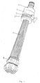
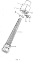
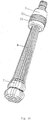
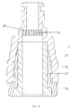
Fig. 1 shows the structure of the filling container ofembodiment 1. -
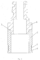
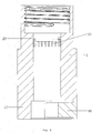
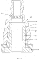
Fig. 2 shows the inside structure of the filling container ofembodiment 1. -
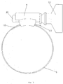
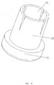
Fig. 3 shows the hose hoop ofembodiment 1. -
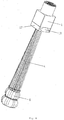
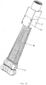
Fig. 4 shows the bundle of hollow tubes ofembodiment 1. -
Fig. 5 showsstructure 1 of the filling container ofembodiment 2. -
Fig. 6 showsstructure 2 of the filling container ofembodiment 2. -
Fig. 7 shows the diagram of the components of the filling container ofembodiment 2. -
Fig. 8 shows the connector, slot, filtering block and the compressing block ofembodiment 2. -
Fig. 9 showsstructure 1 of the filling container of embodiment 3. -
Fig. 10 showsstructure 2 of the filling container of embodiment 3. -
Fig. 11 shows the diagram of the components of the filling container of embodiment 3 -
Fig. 12 shows the connector, slot, filtering block and the compressing block of embodiment 3. -
Fig. 13 showsstructure 1 of the filling container ofembodiment 4. -
Fig. 14 showsstructure 2 of the filling container ofembodiment 4. -
Fig. 15 shows diagram 1 of the connector, sleeve, and the sealing cushion ofembodiment 4. -
Fig. 16 shows diagram 2 of the connector, sleeve, and the sealing cushion ofembodiment 4. -
Fig. 17 shows the diagram of the connector, sleeve, and the sealing cushion ofembodiment 5. -
Fig. 18 shows the diagram of the connector, sleeve, and the sealing cushion ofembodiment 6. -
Fig. 19 shows the structure of the sleeve. - In the figures:
1- Connector; 2- rubber sleeve; 3- convex ring; 4-bundle of hollow tubes; 5-balloon; 6- concave ring; 7-hose hoop; 8- hoop belt; 9-hoop shell; 10- locking worm; 11-handle; 12-first end; 13-second end; 14-perforation; 16-hexagon hollow tube; 17-slot; 18-compressing block; 19-filtering block; 20-step; 21-fixing block; 22-chute; 23-sealing cushion II; 24-sealing cushion I, 25-sleeve; 26-tightening disc; 27-slope; 28-hole a; 29- block a; 30-block b; 31-protruding flange; 32-sealing cushion III; 33-anti slip strip. - The current invention is further illustrated by the following embodiments:
A filling container containing: - a
connector 1, wherein one side of theconnector 1 is provided with an entrance, whereas the other side of the connector is provided with a cavity for tubes, wherein the inside of the cavity for tubes is connected with said entrance; - a bundle of
hollow tubes 4 containing a plurality of hollow tubes, wherein the top part of the bundle is inserted into the said cavity for tubes. - The bottom of
connector 1 is connected with arubber sleeve 2, wherein the bottom side of therubber sleeve 2 is open and forms said cavity for tubes and the top part of the bundle of thehollow tubes 4 inserts into the rubber sleeve; and the constraining element contains a tightening device which circles around the rubber sleeve, wherein the tightening device tightens the rubber sleeve and makes the rubber sleeve constrain the bundle of hollow tubes. Preferably, the side of theconnector 1, from which the water comes, extends downwards and forms a convex ring 3. The top part of therubber sleeve 2 encloses the convex ring 3 and overlaps with the convex ring 3. - The containers are installed at the bottom part of hollow tubes through an elastic fixing element. The inner cavity of the container is connected with the inner channels of the hollow tubes.
- Specifically, each container is a
balloon 5 or a blood collecting bottle or a urine collecting bottle or other containers which are used to collect liquid or gas. When the containers areballoons 5 and when the water inside the balloon reaches certain weight, the balloon is basically full of water. Since the balloon full of water is heavier than the tightening force, the balloon falls off automatically. The elastic fixing element seals the balloon full of water automatically. Alternatively, when the balloon is full of water, the balloon can be taken off by hand. When the containers are blood collecting bottles or urine collecting bottles, the connector is connected with corresponding conducting tubes, which draw blood or urine from people or animals. Said connector can be an external connector, can internal connector, tubular connector or a spiral connector, as long as it can draw water and keep pressure. - The tightening device circles around the outer wall of the
rubber sleeve 2, wherein the tightening device tightens the rubber sleeve and makes the rubber sleeve constrain the bundle ofhollow tubes 4. - The
hollow tubes 4 comprise a plurality of hollow tubes whose cross sections are hexagon and form a bundle ofhollow tubes 4 which has a honeycomb shaped cross section. - Alternatively the
hollow tubes 4 comprise a plurality hollow tubes which have circular cross sections. - The outer wall of the
rubber sleeve 2 bends towards inside and forms aconcave ring 6, wherein the tightening device is located insideconcave ring 6, in order to prevent the tightening device from falling off. Alternatively, the bottom peripheral of the rubber sleeve extends outwards to form a retaining ring. The retaining ring retains the tightening device and prevents the tightening device from falling off.
The tightening device is a ribbon, a rope, a rubber band or ahose hoop 7. - The
hose hoop 7 includes a hoop belt 8, a hoop shell 9 and a lockingworm 10, wherein the hoop shell 9 is hollow and the inside of the hoop shell is a hole, the lockingworm 10 is located inside the hole of the hoop shell 9, the hoop shell 9 is fixed on oneside 12 of the hoop belt 8, and theother side 13 of the hoop belt 8 extends through the hole of the hoop shell 9, and theperforations 14 of the other side the hoop belt 8 match with the screw thread of the lockingworm 10, and the lockingworm 10 tightens the hoop belt so as the rubber sleeve, so that the rubber sleeve constrains thehollow tubes 4. Specifically, the tail of the locking worm extends backwards to form ahandle 11. Through the handle, it is easier to execute forces, which facilitates operation. - Said connector is a pacifier connector.
- Said elastic fixing element is a rubber or an elastic rubber ring or a clamp.
- Said hollow tubes are flexible hollow tubes.
-
Embodiment 2 is partially identical withEmbodiment 1 with the following differences:
One side of the connector extends toward outside and forms aslot 17, and the constraining element is a compressingblock 18, wherein the compressingblock 18 can be removably installed inside theslot 17, and theslot 17 and the compressingblock 18 form the cavity for tubes. - The compressing surface of the compressing block has a shape of circular arc. The compressing surface and the side surface of the inner all of the slot form a circular opening. At this time, the hollow tubes have shapes corresponding to the shape of the opening. There is a sealing cushion II 23 between the several hollow tubes and the side wall of the opening. Part of the sealing cushion II 23 is fixed on the compressing surface of the compressing block, and other part is fixed on the inner wall of the
slot 17. These two parts of the sealing cushion II 23 form a circular soft cushion. - The two sides of the compressing block are provided with a fixing
block 21 respectively. The inner wall of the slot has achute 22 which corresponds with the fixingblock 21. The fixing block and thechute 22 are connected through a fixing element. Specifically, the fixing element is a screw or a bolt. - The inner side of the connector is connected with the entrance. The channel of the cavity for tubes is provided with a
filtering block 19. Thefiltering block 19 is provided with several holes which extend from top to bottom. The filtering block is located above the hollow tubes. The shape of thefiltering block 19 corresponds with the liquid channels. Thefiltering block 19 is connected with the side wall of the shell body with screws, or with cement, or clamps. The inside of the connector is connected with the entrance. The inner wall of the channel of the cavity for tubes has steps, wherein the top of the filtering block touches thestep 20 and the bottom of the filtering block touches the top of the hollow tubes and stabilizes. - The compressing
block 18 is connected with the shell body with screws or with cement or clamps. Preferably, the present invention uses screws. - Embodiment 3 is almost the same as
embodiment 2 with the following differences:
The compressing surface of the compressingblock 18 is a flat surface. The compressing surface and the inner side wall of theslot 17 form a square opening. - The
hollow tubes 4 have several layers of hollow tubes. A sealing soft cushion I 24 is provided between the neighboring two layers of hollow tubes. Said layer of hollow tubes is consisted of several hollow tubes lying side by side. The cross section of the hollow tubes is circular or hexagon. -
Embodiment 4 is almost the same asembodiment 2 with the following differences:
One side of the connector is provided with asleeve 25, wherein thesleeve 25 is provided with a plurality of tighteningdiscs 26, and the tighteningdiscs 26 form said cavity for tubes. The inner wall of theconnector 1 protrudes toward inside and forms aslope 27, and when thesleeve 25 extends into theconnector 1 and tightens, the surface ofslope 27 resists against the tighteningdiscs 26, so that the tighteningdiscs 26 lean toward inside and tightens thehollow tubes 4. - The
connector 1 is screw connected with thesleeve 25. The top of the external wall of the tighteningdiscs 26 is provided with external screw threads. The surface of theslope 27 and the bottom of the connector are provided with corresponding internal screw threads. When theshell body 17 and thesleeve 25 are screw tightened, the tighteningdiscs 26 at the top of thesleeve 25 shrink inwards, so that thehollow tubes 4 are tightened. - A sealing
cushion III 32 is provided between the hollow tubes and the side wall of the sleeve. The sealing cushion can be directly attached to the inner side of the sleeve. Said sealing soft cushion can be a ring or a sleeve. - The outer wall of the shell body has
anti slip strip 33. -
Embodiment 5 is almost the same asembodiment 4, with the following differences:
Thesleeve 25 is clamping connected with theshell body 17. - The
slope 27 of the inner wall of the shell body is provided with hole a 28. The outer surface of the tighteningdiscs 26 is provided with a block a 29 corresponding with the hole a 28. When the shell body is enclosed into the sleeve, the tighteningdiscs 26 shrink inwards and tighten the hollow tubes. The block a 29 touches the hole a 28 in order to prevent thesleeve 25 from falling off. -
Embodiment 6 is almost the same asembodiment 5 with the following differences:
Thesleeve 25 is clamping connected with theshell body 17. - The bottom part of the shell body extends downwards and forms
several blocks b 30. The bottom part of the sleeve extends radially and forms the protrudingflange 31. The protruding flange is provided withseveral blocks b 30 which correspond with the holes b. When the shell body is enclosed into the sleeve, the tighteningdiscs 26 shrink inwards and tighten the hollow tubes. Theblock b 30 touches the hole b in order to prevent the sleeve from falling off. - The outer walls of the top part of each hollow tube of the bundle of hollow tubes are attached together and form an integral part. Alternatively, each hollow tube is independent to each other. The integral part means: the outer walls are glued together or are melted together to form one part.
- The current invention has a simple structure, is easy to use and can make multiple water balls or balloons or fill the balls with other liquid at the same time. Its efficiency to make water ball or to fill the balls with other liquid is very high. It has high airtightness and can be reused.
Claims (10)
- A filling container, containing:- a connector (1), wherein one side of the connector (1) is provided with an entrance, whereas the other side of the connector (1) is provided with a cavity for tubes, wherein the inside of the cavity for tubes is connected with said entrance;- a bundle of hollow tubes (4) containing a plurality of hollow tubes, wherein the top part of the bundle is inserted into the said cavity for tubes, and- containers, which are installed at the bottom part of hollow tubes through an elastic fixing element, wherein the inner cavity of each container is connected with the inner channels of the hollow tubes;characterized in that it further contains a constraining element, which is installed at the connector close to the cavity for tubes, wherein the constraining element shrinks the cavity for tubes and constrains the bundle of hollow tubes.
- A filling container according to claim 1, characterized in that the bottom of connector (1) is connected with a rubber sleeve (2), wherein the bottom side of the rubber sleeve (2) is open and forms said cavity for tubes and the top part of the bundle of the hollow tubes (4) inserts into the rubber sleeve (2); and the constraining element contains a tightening device which circles around the rubber sleeve (2), wherein the tightening device tightens the rubber sleeve (2) and makes the rubber sleeve (2) constrain the bundle of hollow tubes (4).
- A filling container according to claim 2, characterized in that the tightening device is a ribbon, a rope, a rubber band or a hose hoop (7).
- A filling container according to claim 3, characterized in that the hose hoop (7) includes a hoop belt (8), a hoop shell (9) and a locking worm (10), wherein the hoop shell (9) is hollow and the inside of the hoop shell (9) is a hole, the locking worm (10) is located inside the hole of the hoop shell (9), the hoop shell (9) is fixed on one side (12) of the hoop belt (8), and the other side (13) of the hoop belt (8) extends through the hole of the hoop shell (9), and the perforations (14) of the other side (13) of the hoop belt (8) match with the screw thread of the locking worm (10), and the locking worm (10) tightens the hoop belt (8) so as the rubber sleeve (2), so that the rubber sleeve (2) constrains the hollow tubes.
- A filling container according to claim 2, characterized in that the outer wall of the rubber sleeve (2) bends towards inside and forms a concave ring (6), wherein the tightening device is located inside concave ring (6).
- A filling container according to claim 2, characterized in that the periphery of the bottom side of the rubber sleeve (2) extends toward outside and forms protrusion.
- A filling container according to claim 1, characterized in that one side of the connector (1) extends toward outside and forms a slot, and the constraining element is a compressing block (18), wherein the compressing block (18) can be removably installed inside the slot, and the slot and the compressing block (18) form the cavity for tubes.
- A filling container according to claim 1, characterized in that one side of the connector (1) is provided with a sleeve (25), wherein the sleeve (25) is provided with a plurality of tightening discs (26), and the tightening discs (26) form said cavity for tubes; and the inside wall of the connector (1) protrudes toward inside and forms a slope, and when the sleeve extends into the connector and tightens, the surface of slope (27) resists against the tightening discs (26), so that the tightening discs (26) lean toward inside and tightens the hollow tubes.
- A filling container according to claim 2, characterized in that the hollow tubes comprise a plurality of hollow tubes whose cross sections are hexagon (16) and form a bundle of hollow tubes (4) which has a honeycomb shaped cross section, or the hollow tubes comprise a plurality hollow tubes which have circular cross sections.
- A filling container according to any claim of claims 1 to 9, characterized in that the top of each hollow tube in the bundle form an integral part, or, each hollow tube is independent of each other; wherein the integral part means: the outer wall of the top of the hollow tubes are glued to each other via glue or are melted to each other.
Priority Applications (4)
| Application Number | Priority Date | Filing Date | Title |
|---|---|---|---|
| PL17151714T PL3207970T3 (en) | 2016-02-20 | 2017-01-17 | A filling container |
| SI201730018T SI3207970T1 (en) | 2016-02-20 | 2017-01-17 | A filling container |
| RS20190002A RS58155B1 (en) | 2016-02-20 | 2017-01-17 | A filling container |
| HRP20182068TT HRP20182068T1 (en) | 2016-02-20 | 2018-12-06 | A filling container |
Applications Claiming Priority (4)
| Application Number | Priority Date | Filing Date | Title |
|---|---|---|---|
| CN201620131221 | 2016-02-20 | ||
| CN201620131314 | 2016-02-20 | ||
| CN201620450162 | 2016-05-17 | ||
| CN201620974741.4U CN206494150U (en) | 2016-02-20 | 2016-08-26 | A kind of container filling |
Publications (2)
| Publication Number | Publication Date |
|---|---|
| EP3207970A1 EP3207970A1 (en) | 2017-08-23 |
| EP3207970B1 true EP3207970B1 (en) | 2018-11-07 |
Family
ID=57914702
Family Applications (1)
| Application Number | Title | Priority Date | Filing Date |
|---|---|---|---|
| EP17151714.7A Active EP3207970B1 (en) | 2016-02-20 | 2017-01-17 | A filling container |
Country Status (5)
| Country | Link |
|---|---|
| EP (1) | EP3207970B1 (en) |
| PL (1) | PL3207970T3 (en) |
| RS (1) | RS58155B1 (en) |
| SI (1) | SI3207970T1 (en) |
| WO (1) | WO2017140189A1 (en) |
Families Citing this family (3)
| Publication number | Priority date | Publication date | Assignee | Title |
|---|---|---|---|---|
| US20210186394A1 (en) * | 2019-12-20 | 2021-06-24 | Becton, Dickinson And Company | Catheter extension set and related methods |
| BR112023006359A2 (en) | 2020-10-12 | 2023-05-09 | Becton Dickinson Co | SYRINGE FOR BLOOD COLLECTION WITH PROTECTION AGAINST HEMOLYSIS |
| USD968519S1 (en) * | 2021-11-03 | 2022-11-01 | Canxing Zhu | Device for filling multiple water balloons |
Citations (4)
| Publication number | Priority date | Publication date | Assignee | Title |
|---|---|---|---|---|
| CN204193466U (en) * | 2014-11-03 | 2015-03-11 | 汕头市顶级玩具有限公司 | A kind of can the water balloon of rapid water filling |
| CN104436683A (en) * | 2014-11-25 | 2015-03-25 | 李勇 | Water bomb filling device |
| CN104986364A (en) * | 2015-07-27 | 2015-10-21 | 深圳方一信息技术有限公司 | Fluid filling device for elastic containers |
| CN205198964U (en) * | 2015-12-01 | 2016-05-04 | 昆山优瑞全精密组件有限公司 | Subassembly is restrainted to aqueous vapor ball |
Family Cites Families (8)
| Publication number | Priority date | Publication date | Assignee | Title |
|---|---|---|---|---|
| US7090257B2 (en) * | 2002-04-16 | 2006-08-15 | Twin Bay Medical, Inc. | Barb clamp |
| CN202493827U (en) * | 2012-03-15 | 2012-10-17 | 深圳市沃尔奔达新能源股份有限公司 | Hose strap |
| US9051066B1 (en) | 2014-02-07 | 2015-06-09 | Tinnus Enterprises, Llc | System and method for filling containers with fluids |
| CN204250477U (en) * | 2014-11-12 | 2015-04-08 | 刘晓蓉 | The device filling fluid to container and the device that can inflate to multiple balloon the same time |
| CN204293867U (en) * | 2014-11-25 | 2015-04-29 | 李勇 | A kind of water bullet filling machine |
| US20160368627A1 (en) * | 2015-06-19 | 2016-12-22 | Telebrands Corp. | System, device, and method for filling at least one balloon |
| US20160368628A1 (en) * | 2015-06-19 | 2016-12-22 | Telebrands Corp. | System, device, and method for filling at least one balloon |
| ES1155283U (en) * | 2016-04-06 | 2016-04-27 | Xiaowei YE | Device for filling balloons with water (Machine-translation by Google Translate, not legally binding) |
-
2017
- 2017-01-05 WO PCT/CN2017/070211 patent/WO2017140189A1/en active Application Filing
- 2017-01-17 SI SI201730018T patent/SI3207970T1/en unknown
- 2017-01-17 EP EP17151714.7A patent/EP3207970B1/en active Active
- 2017-01-17 RS RS20190002A patent/RS58155B1/en unknown
- 2017-01-17 PL PL17151714T patent/PL3207970T3/en unknown
Patent Citations (4)
| Publication number | Priority date | Publication date | Assignee | Title |
|---|---|---|---|---|
| CN204193466U (en) * | 2014-11-03 | 2015-03-11 | 汕头市顶级玩具有限公司 | A kind of can the water balloon of rapid water filling |
| CN104436683A (en) * | 2014-11-25 | 2015-03-25 | 李勇 | Water bomb filling device |
| CN104986364A (en) * | 2015-07-27 | 2015-10-21 | 深圳方一信息技术有限公司 | Fluid filling device for elastic containers |
| CN205198964U (en) * | 2015-12-01 | 2016-05-04 | 昆山优瑞全精密组件有限公司 | Subassembly is restrainted to aqueous vapor ball |
Also Published As
| Publication number | Publication date |
|---|---|
| WO2017140189A1 (en) | 2017-08-24 |
| EP3207970A1 (en) | 2017-08-23 |
| PL3207970T3 (en) | 2019-03-29 |
| RS58155B1 (en) | 2019-02-28 |
| SI3207970T1 (en) | 2019-02-28 |
Similar Documents
| Publication | Publication Date | Title |
|---|---|---|
| DK3207970T3 (en) | A REFILLER | |
| EP3207970B1 (en) | A filling container | |
| MXPA02001549A (en) | Method for producing a bicycle wheel rim, apparatus for implementing the method and bicycle wheel rim obtained thereby. | |
| GB2561322A (en) | Apparatus, system and method for filling containers with fluid | |
| CN204258247U (en) | Cable tube block head | |
| US9643777B2 (en) | Inflatable refuse containers and methods of use | |
| CA2073978A1 (en) | Drum liner assembly | |
| DE60137448D1 (en) | BARREL FOR REMOVING LIQUIDS AND PRESSURE PUSH | |
| CN104309913B (en) | Fixing structure for bottle cap and bottle | |
| CN207418401U (en) | A kind of enhanced micro-pore aeration component | |
| CN203442411U (en) | Tube cover for tube plugging | |
| ATE286578T1 (en) | DEVICE FOR LIMITING THE PROPAGATION OF DEFORMATION IN A DOUBLE-WALLED WRAPPED PIPE STRING | |
| MX2012002092A (en) | An apparatus and method for containing fluid or gas released from a pipe. | |
| WO2022082420A1 (en) | Protective gas-shielding structure for stainless steel pipeline welding | |
| CN107355544B (en) | Be used for stainless steel pipeline welded inflatable seal device | |
| CN104843885A (en) | Aeration device for sewage treatment | |
| CN204021472U (en) | A kind of Multifunctional bottle stopper | |
| US2273837A (en) | Faucet connector | |
| CN209004058U (en) | A kind of saliva acquisition preservation pipe for being able to achieve a variety of preservation liquid and being mixed with saliva | |
| CN206494150U (en) | A kind of container filling | |
| DE102004023249A1 (en) | Process to insert selected catalyst rings into battery of reactor tubes followed by manual removal as required | |
| CN205677618U (en) | A kind of outer tube sleeve of disposable carbon dioxide blasting cartridge band special valve | |
| CN107006416B (en) | Eel transport case | |
| CN202315167U (en) | Portable badminton racket | |
| CN207367589U (en) | A kind of cucurbit flute |
Legal Events
| Date | Code | Title | Description |
|---|---|---|---|
| STAA | Information on the status of an ep patent application or granted ep patent |
Free format text: STATUS: UNKNOWN |
|
| PUAI | Public reference made under article 153(3) epc to a published international application that has entered the european phase |
Free format text: ORIGINAL CODE: 0009012 |
|
| STAA | Information on the status of an ep patent application or granted ep patent |
Free format text: STATUS: REQUEST FOR EXAMINATION WAS MADE |
|
| 17P | Request for examination filed |
Effective date: 20170220 |
|
| AK | Designated contracting states |
Kind code of ref document: A1 Designated state(s): AL AT BE BG CH CY CZ DE DK EE ES FI FR GB GR HR HU IE IS IT LI LT LU LV MC MK MT NL NO PL PT RO RS SE SI SK SM TR |
|
| AX | Request for extension of the european patent |
Extension state: BA ME |
|
| GRAP | Despatch of communication of intention to grant a patent |
Free format text: ORIGINAL CODE: EPIDOSNIGR1 |
|
| STAA | Information on the status of an ep patent application or granted ep patent |
Free format text: STATUS: GRANT OF PATENT IS INTENDED |
|
| INTG | Intention to grant announced |
Effective date: 20180628 |
|
| GRAJ | Information related to disapproval of communication of intention to grant by the applicant or resumption of examination proceedings by the epo deleted |
Free format text: ORIGINAL CODE: EPIDOSDIGR1 |
|
| STAA | Information on the status of an ep patent application or granted ep patent |
Free format text: STATUS: REQUEST FOR EXAMINATION WAS MADE |
|
| GRAS | Grant fee paid |
Free format text: ORIGINAL CODE: EPIDOSNIGR3 |
|
| STAA | Information on the status of an ep patent application or granted ep patent |
Free format text: STATUS: GRANT OF PATENT IS INTENDED |
|
| INTC | Intention to grant announced (deleted) | ||
| GRAP | Despatch of communication of intention to grant a patent |
Free format text: ORIGINAL CODE: EPIDOSNIGR1 |
|
| GRAA | (expected) grant |
Free format text: ORIGINAL CODE: 0009210 |
|
| STAA | Information on the status of an ep patent application or granted ep patent |
Free format text: STATUS: THE PATENT HAS BEEN GRANTED |
|
| INTG | Intention to grant announced |
Effective date: 20180919 |
|
| AK | Designated contracting states |
Kind code of ref document: B1 Designated state(s): AL AT BE BG CH CY CZ DE DK EE ES FI FR GB GR HR HU IE IS IT LI LT LU LV MC MK MT NL NO PL PT RO RS SE SI SK SM TR |
|
| REG | Reference to a national code |
Ref country code: GB Ref legal event code: FG4D |
|
| REG | Reference to a national code |
Ref country code: CH Ref legal event code: EP Ref country code: AT Ref legal event code: REF Ref document number: 1061391 Country of ref document: AT Kind code of ref document: T Effective date: 20181115 |
|
| REG | Reference to a national code |
Ref country code: HR Ref legal event code: TUEP Ref document number: P20182068 Country of ref document: HR Ref country code: DE Ref legal event code: R096 Ref document number: 602017000775 Country of ref document: DE |
|
| REG | Reference to a national code |
Ref country code: IE Ref legal event code: FG4D |
|
| REG | Reference to a national code |
Ref country code: CH Ref legal event code: NV Representative=s name: VALIPAT S.A. GEVERS SA, CH |
|
| REG | Reference to a national code |
Ref country code: RO Ref legal event code: EPE |
|
| REG | Reference to a national code |
Ref country code: PT Ref legal event code: SC4A Ref document number: 3207970 Country of ref document: PT Date of ref document: 20190117 Kind code of ref document: T Free format text: AVAILABILITY OF NATIONAL TRANSLATION Effective date: 20190107 |
|
| REG | Reference to a national code |
Ref country code: NL Ref legal event code: FP |
|
| REG | Reference to a national code |
Ref country code: HR Ref legal event code: ODRP Ref document number: P20182068 Country of ref document: HR Payment date: 20190107 Year of fee payment: 3 |
|
| REG | Reference to a national code |
Ref country code: DK Ref legal event code: T3 Effective date: 20190123 |
|
| REG | Reference to a national code |
Ref country code: SE Ref legal event code: TRGR |
|
| REG | Reference to a national code |
Ref country code: HR Ref legal event code: T1PR Ref document number: P20182068 Country of ref document: HR |
|
| REG | Reference to a national code |
Ref country code: NO Ref legal event code: T2 Effective date: 20181107 |
|
| REG | Reference to a national code |
Ref country code: ES Ref legal event code: FG2A Ref document number: 2704300 Country of ref document: ES Kind code of ref document: T3 Effective date: 20190315 |
|
| REG | Reference to a national code |
Ref country code: LT Ref legal event code: MG4D |
|
| REG | Reference to a national code |
Ref country code: CH Ref legal event code: PCAR Free format text: NEW ADDRESS: RUE DES NOYERS 11, 2000 NEUCHATEL (CH) |
|
| REG | Reference to a national code |
Ref country code: GR Ref legal event code: EP Ref document number: 20180403886 Country of ref document: GR Effective date: 20190422 |
|
| PG25 | Lapsed in a contracting state [announced via postgrant information from national office to epo] |
Ref country code: LV Free format text: LAPSE BECAUSE OF FAILURE TO SUBMIT A TRANSLATION OF THE DESCRIPTION OR TO PAY THE FEE WITHIN THE PRESCRIBED TIME-LIMIT Effective date: 20181107 Ref country code: IS Free format text: LAPSE BECAUSE OF FAILURE TO SUBMIT A TRANSLATION OF THE DESCRIPTION OR TO PAY THE FEE WITHIN THE PRESCRIBED TIME-LIMIT Effective date: 20190307 Ref country code: LT Free format text: LAPSE BECAUSE OF FAILURE TO SUBMIT A TRANSLATION OF THE DESCRIPTION OR TO PAY THE FEE WITHIN THE PRESCRIBED TIME-LIMIT Effective date: 20181107 |
|
| PG25 | Lapsed in a contracting state [announced via postgrant information from national office to epo] |
Ref country code: AL Free format text: LAPSE BECAUSE OF FAILURE TO SUBMIT A TRANSLATION OF THE DESCRIPTION OR TO PAY THE FEE WITHIN THE PRESCRIBED TIME-LIMIT Effective date: 20181107 |
|
| REG | Reference to a national code |
Ref country code: HU Ref legal event code: AG4A Ref document number: E042749 Country of ref document: HU |
|
| REG | Reference to a national code |
Ref country code: DE Ref legal event code: R097 Ref document number: 602017000775 Country of ref document: DE |
|
| PG25 | Lapsed in a contracting state [announced via postgrant information from national office to epo] |
Ref country code: EE Free format text: LAPSE BECAUSE OF FAILURE TO SUBMIT A TRANSLATION OF THE DESCRIPTION OR TO PAY THE FEE WITHIN THE PRESCRIBED TIME-LIMIT Effective date: 20181107 Ref country code: SM Free format text: LAPSE BECAUSE OF FAILURE TO SUBMIT A TRANSLATION OF THE DESCRIPTION OR TO PAY THE FEE WITHIN THE PRESCRIBED TIME-LIMIT Effective date: 20181107 Ref country code: MC Free format text: LAPSE BECAUSE OF FAILURE TO SUBMIT A TRANSLATION OF THE DESCRIPTION OR TO PAY THE FEE WITHIN THE PRESCRIBED TIME-LIMIT Effective date: 20181107 |
|
| PLBE | No opposition filed within time limit |
Free format text: ORIGINAL CODE: 0009261 |
|
| STAA | Information on the status of an ep patent application or granted ep patent |
Free format text: STATUS: NO OPPOSITION FILED WITHIN TIME LIMIT |
|
| 26N | No opposition filed |
Effective date: 20190808 |
|
| REG | Reference to a national code |
Ref country code: HR Ref legal event code: ODRP Ref document number: P20182068 Country of ref document: HR Payment date: 20191216 Year of fee payment: 4 |
|
| PGFP | Annual fee paid to national office [announced via postgrant information from national office to epo] |
Ref country code: CY Payment date: 20200107 Year of fee payment: 4 |
|
| PGFP | Annual fee paid to national office [announced via postgrant information from national office to epo] |
Ref country code: MK Payment date: 20200103 Year of fee payment: 4 |
|
| REG | Reference to a national code |
Ref country code: NL Ref legal event code: PD Owner name: KOOPMAN INTERNATIONAL B.V.; NL Free format text: DETAILS ASSIGNMENT: CHANGE OF OWNER(S), ASSIGNMENT; FORMER OWNER NAME: LIN, HUI Effective date: 20201014 |
|
| REG | Reference to a national code |
Ref country code: DE Ref legal event code: R082 Ref document number: 602017000775 Country of ref document: DE Representative=s name: SKM-IP SCHMID KRAUSS KUTTENKEULER MALESCHA SCH, DE Ref country code: DE Ref legal event code: R082 Ref document number: 602017000775 Country of ref document: DE Representative=s name: BOEHMERT & BOEHMERT ANWALTSPARTNERSCHAFT MBB -, DE Ref country code: DE Ref legal event code: R081 Ref document number: 602017000775 Country of ref document: DE Owner name: KOOPMAN INTERNATIONAL B.V., NL Free format text: FORMER OWNER: HUI, LIN, TAIZHOU CITY, ZHEJIANG, CN |
|
| REG | Reference to a national code |
Ref country code: HR Ref legal event code: ODRP Ref document number: P20182068 Country of ref document: HR Payment date: 20210112 Year of fee payment: 5 |
|
| REG | Reference to a national code |
Ref country code: AT Ref legal event code: UEP Ref document number: 1061391 Country of ref document: AT Kind code of ref document: T Effective date: 20181107 |
|
| REG | Reference to a national code |
Ref country code: GB Ref legal event code: 732E Free format text: REGISTERED BETWEEN 20210121 AND 20210127 |
|
| REG | Reference to a national code |
Ref country code: CH Ref legal event code: NV Representative=s name: TROESCH SCHEIDEGGER WERNER AG, CH Ref country code: CH Ref legal event code: PUE Owner name: KOOPMAN INTERNATIONAL B.V., NL Free format text: FORMER OWNER: LIN, HUI, CN |
|
| REG | Reference to a national code |
Ref country code: HR Ref legal event code: PPPP Ref document number: P20182068 Country of ref document: HR Owner name: KOOPMAN INTERNATIONAL B.V., NL |
|
| REG | Reference to a national code |
Ref country code: LU Ref legal event code: PD Owner name: KOOPMAN INTERNATIONAL B.V.; NL Free format text: FORMER OWNER: LIN, HUI Effective date: 20210225 |
|
| REG | Reference to a national code |
Ref country code: NO Ref legal event code: CHAD Owner name: KOOPMAN INTERNATIONAL B.V., NL Ref country code: NO Ref legal event code: CREP Representative=s name: OSLO PATENTKONTOR AS, HOFFSVEIEN 1A, 0275 OSLO |
|
| REG | Reference to a national code |
Ref country code: FI Ref legal event code: PCE Owner name: KOOPMAN INTERNATIONAL B.V. |
|
| REG | Reference to a national code |
Ref country code: ES Ref legal event code: PC2A Owner name: KOOPMAN INTERNATIONAL B.V. Effective date: 20210323 |
|
| REG | Reference to a national code |
Ref country code: SK Ref legal event code: PC4A Ref document number: E 29664 Country of ref document: SK Owner name: KOOPMAN INTERNATIONAL B.V., HH AMSTERDAM, NL Free format text: FORMER OWNER: LIN, HUI, TAIZHOU CITY ZHEJIANG, CN Effective date: 20210423 Ref country code: HU Ref legal event code: GB9C Owner name: KOOPMAN INTERNATIONAL B.V., NL Free format text: FORMER OWNER(S): LIN, HUI, CN Ref country code: BE Ref legal event code: PD Owner name: KOOPMAN INTERNATIONAL B.V.; NL Free format text: DETAILS ASSIGNMENT: CHANGE OF OWNER(S), ASSIGNMENT; FORMER OWNER NAME: GEVERS PATENTS Effective date: 20210301 |
|
| REG | Reference to a national code |
Ref country code: SI Ref legal event code: SP73 Owner name: KOOPMAN INTERNATIONAL B.V.; NL Effective date: 20210426 |
|
| REG | Reference to a national code |
Ref country code: AT Ref legal event code: PC Ref document number: 1061391 Country of ref document: AT Kind code of ref document: T Owner name: KOOPMAN INTERNATIONAL B.V., NL Effective date: 20210505 |
|
| PG25 | Lapsed in a contracting state [announced via postgrant information from national office to epo] |
Ref country code: CY Free format text: LAPSE BECAUSE OF NON-PAYMENT OF DUE FEES Effective date: 20210117 |
|
| REG | Reference to a national code |
Ref country code: HR Ref legal event code: ODRP Ref document number: P20182068 Country of ref document: HR Payment date: 20211228 Year of fee payment: 6 |
|
| REG | Reference to a national code |
Ref country code: HR Ref legal event code: ODRP Ref document number: P20182068 Country of ref document: HR Payment date: 20221222 Year of fee payment: 7 |
|
| REG | Reference to a national code |
Ref country code: DE Ref legal event code: R082 Ref document number: 602017000775 Country of ref document: DE Representative=s name: SKM-IP SCHMID KRAUSS KUTTENKEULER MALESCHA SCH, DE |
|
| REG | Reference to a national code |
Ref country code: HR Ref legal event code: ODRP Ref document number: P20182068 Country of ref document: HR Payment date: 20240104 Year of fee payment: 8 |
|
| PGFP | Annual fee paid to national office [announced via postgrant information from national office to epo] |
Ref country code: NL Payment date: 20240103 Year of fee payment: 8 |
|
| PGFP | Annual fee paid to national office [announced via postgrant information from national office to epo] |
Ref country code: LU Payment date: 20240104 Year of fee payment: 8 |
|
| PGFP | Annual fee paid to national office [announced via postgrant information from national office to epo] |
Ref country code: GR Payment date: 20240129 Year of fee payment: 8 |
|
| PGFP | Annual fee paid to national office [announced via postgrant information from national office to epo] |
Ref country code: IE Payment date: 20240104 Year of fee payment: 8 Ref country code: ES Payment date: 20240205 Year of fee payment: 8 |
|
| PGFP | Annual fee paid to national office [announced via postgrant information from national office to epo] |
Ref country code: AT Payment date: 20240104 Year of fee payment: 8 |
|
| PGFP | Annual fee paid to national office [announced via postgrant information from national office to epo] |
Ref country code: RO Payment date: 20240105 Year of fee payment: 8 Ref country code: HU Payment date: 20240208 Year of fee payment: 8 Ref country code: FI Payment date: 20240104 Year of fee payment: 8 Ref country code: DE Payment date: 20240104 Year of fee payment: 8 Ref country code: CZ Payment date: 20240104 Year of fee payment: 8 Ref country code: BG Payment date: 20240103 Year of fee payment: 8 Ref country code: GB Payment date: 20240103 Year of fee payment: 8 Ref country code: SK Payment date: 20240104 Year of fee payment: 8 Ref country code: CH Payment date: 20240202 Year of fee payment: 8 Ref country code: PT Payment date: 20240103 Year of fee payment: 8 |
|
| PGFP | Annual fee paid to national office [announced via postgrant information from national office to epo] |
Ref country code: SI Payment date: 20240103 Year of fee payment: 8 |
|
| PGFP | Annual fee paid to national office [announced via postgrant information from national office to epo] |
Ref country code: TR Payment date: 20240103 Year of fee payment: 8 Ref country code: SE Payment date: 20240103 Year of fee payment: 8 Ref country code: RS Payment date: 20240105 Year of fee payment: 8 Ref country code: PL Payment date: 20240103 Year of fee payment: 8 Ref country code: NO Payment date: 20240104 Year of fee payment: 8 Ref country code: MT Payment date: 20240104 Year of fee payment: 8 Ref country code: IT Payment date: 20240109 Year of fee payment: 8 Ref country code: HR Payment date: 20240104 Year of fee payment: 8 Ref country code: FR Payment date: 20240103 Year of fee payment: 8 Ref country code: DK Payment date: 20240108 Year of fee payment: 8 Ref country code: BE Payment date: 20240103 Year of fee payment: 8 |