EP3207615B1 - Power path information generation device, method for generating power path information, and computer program - Google Patents
Power path information generation device, method for generating power path information, and computer program Download PDFInfo
- Publication number
- EP3207615B1 EP3207615B1 EP15784493.7A EP15784493A EP3207615B1 EP 3207615 B1 EP3207615 B1 EP 3207615B1 EP 15784493 A EP15784493 A EP 15784493A EP 3207615 B1 EP3207615 B1 EP 3207615B1
- Authority
- EP
- European Patent Office
- Prior art keywords
- nodes
- agent
- node
- power
- battery
- Prior art date
- Legal status (The legal status is an assumption and is not a legal conclusion. Google has not performed a legal analysis and makes no representation as to the accuracy of the status listed.)
- Active
Links
- 238000000034 method Methods 0.000 title claims description 72
- 238000004590 computer program Methods 0.000 title claims description 7
- 238000004891 communication Methods 0.000 claims description 30
- 230000002457 bidirectional effect Effects 0.000 claims description 6
- 230000014509 gene expression Effects 0.000 description 111
- 230000005540 biological transmission Effects 0.000 description 79
- 238000010586 diagram Methods 0.000 description 17
- 230000008569 process Effects 0.000 description 17
- 230000006870 function Effects 0.000 description 9
- 238000012545 processing Methods 0.000 description 8
- 230000005856 abnormality Effects 0.000 description 7
- 238000005259 measurement Methods 0.000 description 7
- 230000002159 abnormal effect Effects 0.000 description 6
- 230000000694 effects Effects 0.000 description 6
- 230000009467 reduction Effects 0.000 description 5
- 230000004044 response Effects 0.000 description 5
- 238000012951 Remeasurement Methods 0.000 description 4
- 238000012546 transfer Methods 0.000 description 4
- 238000005516 engineering process Methods 0.000 description 3
- 230000003071 parasitic effect Effects 0.000 description 3
- 238000004364 calculation method Methods 0.000 description 2
- 230000008859 change Effects 0.000 description 2
- 239000000463 material Substances 0.000 description 2
- 230000007246 mechanism Effects 0.000 description 2
- 230000004048 modification Effects 0.000 description 2
- 238000012986 modification Methods 0.000 description 2
- 238000012544 monitoring process Methods 0.000 description 2
- 230000001151 other effect Effects 0.000 description 2
- 230000004083 survival effect Effects 0.000 description 2
- 230000000007 visual effect Effects 0.000 description 2
- 230000004075 alteration Effects 0.000 description 1
- 238000006243 chemical reaction Methods 0.000 description 1
- 230000003247 decreasing effect Effects 0.000 description 1
- 238000012217 deletion Methods 0.000 description 1
- 230000037430 deletion Effects 0.000 description 1
- 230000001419 dependent effect Effects 0.000 description 1
- 238000013461 design Methods 0.000 description 1
- 239000000284 extract Substances 0.000 description 1
- 238000010248 power generation Methods 0.000 description 1
- 238000005406 washing Methods 0.000 description 1
Images


Classifications
-
- H—ELECTRICITY
- H02—GENERATION; CONVERSION OR DISTRIBUTION OF ELECTRIC POWER
- H02J—CIRCUIT ARRANGEMENTS OR SYSTEMS FOR SUPPLYING OR DISTRIBUTING ELECTRIC POWER; SYSTEMS FOR STORING ELECTRIC ENERGY
- H02J1/00—Circuit arrangements for dc mains or dc distribution networks
-
- G—PHYSICS
- G05—CONTROLLING; REGULATING
- G05B—CONTROL OR REGULATING SYSTEMS IN GENERAL; FUNCTIONAL ELEMENTS OF SUCH SYSTEMS; MONITORING OR TESTING ARRANGEMENTS FOR SUCH SYSTEMS OR ELEMENTS
- G05B15/00—Systems controlled by a computer
- G05B15/02—Systems controlled by a computer electric
-
- H—ELECTRICITY
- H02—GENERATION; CONVERSION OR DISTRIBUTION OF ELECTRIC POWER
- H02J—CIRCUIT ARRANGEMENTS OR SYSTEMS FOR SUPPLYING OR DISTRIBUTING ELECTRIC POWER; SYSTEMS FOR STORING ELECTRIC ENERGY
- H02J1/00—Circuit arrangements for dc mains or dc distribution networks
- H02J1/10—Parallel operation of dc sources
- H02J1/102—Parallel operation of dc sources being switching converters
-
- H—ELECTRICITY
- H02—GENERATION; CONVERSION OR DISTRIBUTION OF ELECTRIC POWER
- H02J—CIRCUIT ARRANGEMENTS OR SYSTEMS FOR SUPPLYING OR DISTRIBUTING ELECTRIC POWER; SYSTEMS FOR STORING ELECTRIC ENERGY
- H02J13/00—Circuit arrangements for providing remote indication of network conditions, e.g. an instantaneous record of the open or closed condition of each circuitbreaker in the network; Circuit arrangements for providing remote control of switching means in a power distribution network, e.g. switching in and out of current consumers by using a pulse code signal carried by the network
- H02J13/00006—Circuit arrangements for providing remote indication of network conditions, e.g. an instantaneous record of the open or closed condition of each circuitbreaker in the network; Circuit arrangements for providing remote control of switching means in a power distribution network, e.g. switching in and out of current consumers by using a pulse code signal carried by the network characterised by information or instructions transport means between the monitoring, controlling or managing units and monitored, controlled or operated power network element or electrical equipment
- H02J13/00016—Circuit arrangements for providing remote indication of network conditions, e.g. an instantaneous record of the open or closed condition of each circuitbreaker in the network; Circuit arrangements for providing remote control of switching means in a power distribution network, e.g. switching in and out of current consumers by using a pulse code signal carried by the network characterised by information or instructions transport means between the monitoring, controlling or managing units and monitored, controlled or operated power network element or electrical equipment using a wired telecommunication network or a data transmission bus
-
- H—ELECTRICITY
- H02—GENERATION; CONVERSION OR DISTRIBUTION OF ELECTRIC POWER
- H02J—CIRCUIT ARRANGEMENTS OR SYSTEMS FOR SUPPLYING OR DISTRIBUTING ELECTRIC POWER; SYSTEMS FOR STORING ELECTRIC ENERGY
- H02J7/00—Circuit arrangements for charging or depolarising batteries or for supplying loads from batteries
- H02J7/34—Parallel operation in networks using both storage and other dc sources, e.g. providing buffering
- H02J7/35—Parallel operation in networks using both storage and other dc sources, e.g. providing buffering with light sensitive cells
-
- Y—GENERAL TAGGING OF NEW TECHNOLOGICAL DEVELOPMENTS; GENERAL TAGGING OF CROSS-SECTIONAL TECHNOLOGIES SPANNING OVER SEVERAL SECTIONS OF THE IPC; TECHNICAL SUBJECTS COVERED BY FORMER USPC CROSS-REFERENCE ART COLLECTIONS [XRACs] AND DIGESTS
- Y02—TECHNOLOGIES OR APPLICATIONS FOR MITIGATION OR ADAPTATION AGAINST CLIMATE CHANGE
- Y02E—REDUCTION OF GREENHOUSE GAS [GHG] EMISSIONS, RELATED TO ENERGY GENERATION, TRANSMISSION OR DISTRIBUTION
- Y02E40/00—Technologies for an efficient electrical power generation, transmission or distribution
- Y02E40/70—Smart grids as climate change mitigation technology in the energy generation sector
-
- Y—GENERAL TAGGING OF NEW TECHNOLOGICAL DEVELOPMENTS; GENERAL TAGGING OF CROSS-SECTIONAL TECHNOLOGIES SPANNING OVER SEVERAL SECTIONS OF THE IPC; TECHNICAL SUBJECTS COVERED BY FORMER USPC CROSS-REFERENCE ART COLLECTIONS [XRACs] AND DIGESTS
- Y02—TECHNOLOGIES OR APPLICATIONS FOR MITIGATION OR ADAPTATION AGAINST CLIMATE CHANGE
- Y02E—REDUCTION OF GREENHOUSE GAS [GHG] EMISSIONS, RELATED TO ENERGY GENERATION, TRANSMISSION OR DISTRIBUTION
- Y02E60/00—Enabling technologies; Technologies with a potential or indirect contribution to GHG emissions mitigation
-
- Y—GENERAL TAGGING OF NEW TECHNOLOGICAL DEVELOPMENTS; GENERAL TAGGING OF CROSS-SECTIONAL TECHNOLOGIES SPANNING OVER SEVERAL SECTIONS OF THE IPC; TECHNICAL SUBJECTS COVERED BY FORMER USPC CROSS-REFERENCE ART COLLECTIONS [XRACs] AND DIGESTS
- Y04—INFORMATION OR COMMUNICATION TECHNOLOGIES HAVING AN IMPACT ON OTHER TECHNOLOGY AREAS
- Y04S—SYSTEMS INTEGRATING TECHNOLOGIES RELATED TO POWER NETWORK OPERATION, COMMUNICATION OR INFORMATION TECHNOLOGIES FOR IMPROVING THE ELECTRICAL POWER GENERATION, TRANSMISSION, DISTRIBUTION, MANAGEMENT OR USAGE, i.e. SMART GRIDS
- Y04S10/00—Systems supporting electrical power generation, transmission or distribution
- Y04S10/12—Monitoring or controlling equipment for energy generation units, e.g. distributed energy generation [DER] or load-side generation
- Y04S10/123—Monitoring or controlling equipment for energy generation units, e.g. distributed energy generation [DER] or load-side generation the energy generation units being or involving renewable energy sources
-
- Y—GENERAL TAGGING OF NEW TECHNOLOGICAL DEVELOPMENTS; GENERAL TAGGING OF CROSS-SECTIONAL TECHNOLOGIES SPANNING OVER SEVERAL SECTIONS OF THE IPC; TECHNICAL SUBJECTS COVERED BY FORMER USPC CROSS-REFERENCE ART COLLECTIONS [XRACs] AND DIGESTS
- Y04—INFORMATION OR COMMUNICATION TECHNOLOGIES HAVING AN IMPACT ON OTHER TECHNOLOGY AREAS
- Y04S—SYSTEMS INTEGRATING TECHNOLOGIES RELATED TO POWER NETWORK OPERATION, COMMUNICATION OR INFORMATION TECHNOLOGIES FOR IMPROVING THE ELECTRICAL POWER GENERATION, TRANSMISSION, DISTRIBUTION, MANAGEMENT OR USAGE, i.e. SMART GRIDS
- Y04S40/00—Systems for electrical power generation, transmission, distribution or end-user application management characterised by the use of communication or information technologies, or communication or information technology specific aspects supporting them
- Y04S40/12—Systems for electrical power generation, transmission, distribution or end-user application management characterised by the use of communication or information technologies, or communication or information technology specific aspects supporting them characterised by data transport means between the monitoring, controlling or managing units and monitored, controlled or operated electrical equipment
- Y04S40/124—Systems for electrical power generation, transmission, distribution or end-user application management characterised by the use of communication or information technologies, or communication or information technology specific aspects supporting them characterised by data transport means between the monitoring, controlling or managing units and monitored, controlled or operated electrical equipment using wired telecommunication networks or data transmission busses
Definitions
- the present disclosure relates to a power path information generation device, a method for generating power path information, and computer program.
- Document WO2014/072793 A1 states in its abstract an architecture system of a local grid made up of at least two single nodes constituting micro-grids, each managed by a self-configurable node controller that is also connected to the controllers of the other nodes and to the single energy generation, storage and consumption elements of its own node, said elements being variable in their configuration and dynamic in their behaviour; said controller also optimizing the energy transfers according to specific management logics of the routine and sub-routine type.
- connection topology may vary dynamically, and thus information on a changed connection topology for every change in connection topology is necessary to be collected and distributed to each node, which is inefficient.
- a novel and improved power path information generation device capable of achieving an efficient transmission of direct-current power by automatically collecting the connection topology of a node that transmits and receives the direct-current power.
- the description is based on the assumption that an environment becomes increasingly popular in which each consumer is provided with a battery server having a storage battery, the storage battery stores power using a commercial power supply or power generated from a natural energy source such as solar, wind, and geothermal, and the power stored in the storage battery drives electrical appliances.
- a power interchange system is designed for interchanging power between consumers, as described above.
- the power interchange system allows a battery server of a consumer having extra power to supply power to the battery server of the consumer having insufficient power.
- the amount of power transmission exchanged between the power transmission side and the power reception side When customers supply direct-current power with each other, it is preferable to previously determine the amount of power transmission exchanged between the power transmission side and the power reception side.
- the predetermined amount of power is necessary to be properly supplied between the power transmission side and the power reception side. This is because the transmission and reception of the proper amount of power between the power transmission side and the power reception side are necessary to exchange power between the power transmission side and the power reception side.
- the existing alternating-current power grid (AC grid) is intended to supply power from a power company to each home in a one-way direction, the distribution wiring is made using power lines that sufficiently withstand the total amount of power consumed in each home.
- AC grid alternating-current power grid
- the number of power supply contracts is increased, it becomes necessary to use a material of wiring in consideration of the maximum number of contracts as a power transmission line, which leads to an increased cost.
- a power cable of at least approximately 50 meters in length may be necessary between home (customers) connected to each other in the DC grid, or some power cables may be up to several hundred meters in length.
- efficient selection of a power supply destination is necessary to consider power loss that depends on parasitic resistance of the cable.
- the positional relationship between customers is necessary to know to allow for determination of selection of the power supply destination.
- a method of previously checking a connection state by a system administrator in a visual manner, measuring or calculating parasitic resistance value between wires, and re-registering the parasitic resistance value in each device can be considered.
- customers can join the system and withdraw from it of their own free will.
- it is necessary to check the connection configuration and change a setting whenever customers join the system or withdraw from it.
- the present inventor has made intensive studies to provide a technology capable of detecting automatically a connection state by a battery server connected to the DC grid and sharing the detected connection state with another battery server. As a result, the present inventor has developed the technology capable of detecting automatically a connection state by a battery server connected to the DC grid and sharing the detected connection state with another battery server as described below.
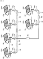
- FIG. 1 is a diagram illustrated to describe an overall configuration example of the power transmission and reception control system according to an embodiment of the present disclosure.
- FIG. 1 illustrates an overall configuration example of the power transmission and reception control system that interchanges direct-current power between battery servers having their own storage batteries. An overall configuration example of the power transmission and reception control system according to an embodiment of the present disclosure will be described with reference to FIG. 1 .
- the power transmission and reception control system 1 is constructed to mutually supply direct-current power as necessary among battery servers provided in the respective consumers (six in FIG. 1 ).
- a consumer 10a is provided with a battery server 100a.
- a consumer 10e is provided with a battery server 100e
- a consumer 10f is provided with a battery server 100f.
- Each of the battery servers 100a to 100f has a rechargeable battery provided inside or outside of each battery server.
- the battery servers 100a to 100f are connected to a direct-current bus line 20 over which direct-current power is mutually supplied among the battery servers as necessary.
- Each of the battery servers 100a to 100f is provided with a bidirectional DC-to-DC converter that converts voltage of a battery and voltage of the direct-current bus line 20 from one level to another.
- the battery servers 100a to 100f are connected to a communication wire 30. When the battery servers 100a to 100f mutually supply direct-current power over the direct-current bus line 20, the battery servers 100a to 100f transmit and receive information over the communication wire 30.
- the communication wire 30 is illustrated as being wired in FIG. 1 , but the communication wire 30 may be wireless.
- the consumers 10a to 10f may be provided with solar panels 200a to 200f, respectively.
- Each of the solar panels 200a to 200f receives irradiation of sunlight and generates electric power.
- the solar panels 200a to 200f are configured so that the generated electric power may be stored in the respective batteries provided in the battery servers 100a to 100f.
- the electric power stored in the battery servers 100a to 100f may be generated by natural energy, such as wind or geothermal, other than sunlight.
- the power transmission and reception control system 1 is characterized by a mechanism for arbitrating power transmission and reception among the battery servers 100a to 100f in such a way that only one of the battery servers 100a to 100f connected to the direct-current bus line 20 has the right to control the transmission and reception of direct-current power over the direct-current bus line 20.
- the power transmission and reception control system 1 according to the present embodiment is configured to have a mechanism that allows only the batter server having the control right among the battery servers 100a to 100f to instruct other battery servers to transmit power stored in their own batteries or to receive power for charging their own batteries, and that prevents a battery server having no control right from performing the power transmission and reception without permission or instruction.
- the power transmission and reception control system 1 efficiently manages the right to control the power transmission and reception of direct-current power, thereby keeping the order of objects to be controlled among the battery servers.
- the battery servers 100a to 100f are configured to acquire a current value from an ammeter 31 and a voltage value from a voltmeter 32.
- the current value and the voltage value are measured at the points connected to the direct-current bus line 20.
- the ammeter 31 and the voltmeter 32 may be provided in the DC-to-DC converter, which will be described later.
- the battery servers 100a to 100f exchange information on the current value and the voltage value with each other via the communication wire 30.
- the battery servers 100a to 100f control their respective bidirectional DC-to-DC converters based on the information on the current value and the voltage value.
- FIG. 2 is a diagram illustrated to describe a functional configuration example of the power transmission and reception control system according to an embodiment of the present disclosure. A functional configuration example of the power transmission and reception control system according to an embodiment of the present disclosure will be described with reference to FIG. 2 .
- the battery server 100a is configured to include a U-Agent 110a, an M-Agent 120a, a GM-Agent 130a, a C-Agent 140a, a DC-to-DC converter 150a, and a battery 160a.
- the battery servers 100b, 100c, and 100d have a configuration similar to the battery server 100a. The components that constitute the battery server 100a will be described.
- the communication wire 30 is composed of two paths (channels) including a communication wire 30a and a communication wire 30b.
- the communication wires 30a and 30b may be physically different wired communication wires, or may be physically identical wired or wireless communication wires, which are divided logically for authentication, encryption, or the like.
- the communication wire 30a allows the U-Agent 110a to communicate with other U-Agents 110b to 110d, and the M-Agent 120a to communicate with other M-Agents 120b to 120d.
- the communication wire 30b allows the GM-Agent 130a to communicate with other GM-Agents 130b to 130d, and the C-Agent 140a to communicate with other C-Agents 140b to 140d.
- the power transmission and reception control system 1 uses separate communication wires for the U-Agent 110a and the M-Agent 120a and for the GM-Agent 130a and the C-Agent 140a.
- the U-Agent 110a and the M-Agent 120a are prevented from directly sending an instruction to the GM-Agent 130a and the C-Agent 140a.
- the GM-Agent 130a and the C-Agent 140a are also prevented from directly sending an instruction to the U-Agent 110a and the M-Agent 120a.
- the U-Agent 110a periodically checks the state of charge (SOC) in the battery 160a. If the state of charge in the battery 160a satisfies a predetermined condition, the U-Agent 110a requests the M-Agent 120a to receive power.
- the request to be sent from the U-Agent 110a to the M-Agent 120a may include a voltage value or current value upon reception of power, a time for receiving power (e.g., start time, end time, and duration), and a state of charge in the battery 160a that stops receiving power.
- the U-Agent 110a refers to a scenario 170a to determine whether the state of charge in the battery 160a satisfies a predetermined condition.
- the scenario 170a describes a condition of the state of charge in the battery 160a, which is used to request the M-Agent 120a to receive power from the U-Agent 110a.
- the condition described in the scenario 170a may include contents of the U-Agent 110a requesting the M-Agent 120a to receive power if the state of charge in the battery 160a is lower than or equal to 20%.
- the U-Agent 110a may have a function that edits contents of the scenario 170a based on the request from the user.
- the contents of the scenario 170a may be described in text, a markup language such as extensible markup language (XML), or a scripting language such as Lisp, Perl, and PHP.
- XML extensible markup language
- PHP a scripting language
- the contents of the scenario 170a may be described in a set of functions.
- the scenario 170a may be edited using a text editor, a dedicated editor, or a web browser.
- the U-Agent 110a may be configured so that a tool capable of editing the contents of the scenario 170a is operable.
- the scenario 170a may describe a way of determining whether power transmission is permitted in response to the request depending on what condition is satisfied. For example, when there is a request for supply of power from another battery server, the scenario 170a may describe contents in which power transmission is permitted in response to the request under the condition that the state of charge in the battery 160a is greater than or equal to 80%. For example, when there is a request for supply of power from another battery server, the scenario 170a may describe contents in which power transmission is permitted in response to the request under the condition that the state of charge in the battery 160a is greater than or equal to 80% and the usage rate per hour of the power is less than or equal to 10%. In other words, the condition described in the scenario 170a may include not only the state of charge in the battery 160a but also the state of usage of electric power stored in the battery 160a.
- the contents of the scenario are possible to be defined independently at the respective batteries. Accordingly, the condition in which power reception is requested or the condition in which power transmission is permitted in response to a request for supply of power from another battery server may be different for each battery server.
- the number of scenarios to be defined at each battery server is not limited to only one.
- the scenario referred to by the U-Agent 110a may be switched into another, depending on the situation.
- the M-Agent 120a When the M-Agent 120a receives a request for power reception from the U-Agent 110a, the M-Agent 120a inquires of the M-Agents 120b, 120c, and 120d of other battery servers about whether they are allowed to transmit power by performing communication among the M-Agents 120b, 120c, and 120d via the communication wire 30a. When the M-Agent 120a receives an inquiry about whether the M-Agent 120a is allowed to transmit power from the M-Agents 120b, 120c, and 120d of other battery servers, the M-Agent 120a responds that power is allowed to be transmitted or not.
- the M-Agent 120a When the M-Agent 120a receives an inquiry as to whether the M-Agent 120a is allowed to transmit power from the M-Agents 120b, 120c, and 120d of other battery servers, the M-Agent 120a may respond that power is allowed to be transmitted. In this case, if the GM-Agent 130a is not started, the M-Agent 120a inquires of the M-Agents 120b, 120c, and 120d of other battery servers about whether the GM-Agents 130b, 130c, and 130d are started over the communication wire 30a. As will be described in detail later, the GM-Agent 130a is started based on the start instruction from the M-Agent 120a and controls the operation of the DC-to-DC converters 150a to 150d of the battery servers.
- the M-Agent 120a determines that the battery server 100a does not have the right to control the power transmission and reception and inquires of the M-Agents 120b, 120c, and 120d of other battery servers about whether they have the right to control the power transmission and reception, that is, whether they are starting or not, over the communication wire 30a. If there is a GM-Agent being started, the M-Agent 120a requests the GM-Agent being started to transmit and receive power through the M-Agent that causes the GM-Agent to start. For example, if the GM-Agent 130b is being started, the M-Agent 120a requests the M-Agent 120b to transmit and receive power through the M-Agent 120b.
- the M-Agent 120a notifies the C-Agent 140a to follow an instruction only from a GM-Agent of the battery server having a control right. For example, the M-Agent 120a notifies identification information, which identifies a GM-Agent of the battery server having a control right, to the C-Agent 140a. when the C-Agent 140a receives the notification of identification information that identifies a GM-Agent of the battery server having a control right, the C-Agent 140a may ignore an instruction from a GM-Agent that contains identification information other than the identification information.
- the GM-Agent 130a is started and activated according to a start instruction from the M-Agent 120a.
- the GM-Agent 130a is stopped and deactivated according to a stop instruction from the M-Agent 120a.
- the activated GM-Agent 130a controls the power transmission and reception by the DC-to-DC converters 150a to 150d through the C-Agents 140a to 140d over the communication wire 30b based on the request for the power transmission and reception from the M-Agents 120a to 120d.
- the GM-Agent 130a performs a process for releasing the control right.
- the GM-Agent 130a is stopped and deactivated according to the stop instruction from the M-Agent 120a.
- the GM-Agent 130a acquires the power transmission capacity and power reception capacity of the respective battery servers 100a to 100d from the C-Agents 140a to 140d over the communication wire 30b.
- the GM-Agent 130a also calculates an amount of electric current that can be transmitted, from the total transmission current amount of the direct-current bus line 20.
- the GM-Agent 130a instructs the C-Agents 140a to 140d to stop transmitting power over the communication wire 30b.
- the C-Agent 140a controls the DC-to-DC converter 150a based on an instruction from the activated (i.e. having a control right) GM-Agent among the GM-Agents 130a to 130d.
- the C-Agent 140a receives the notification from the M-Agent 120a to follow the instruction only from the GM-Agent of the battery server having the control right.
- the C-Agent 140a controls the DC-to-DC converter 150a according to the instruction only from the GM-Agent of the battery server having the control right.
- the C-Agent 140a periodically checks a parameter of the DC-to-DC converter 150a, and warns a target transmitter or receiver of power upon occurrence of an abnormality in the parameter of the DC-to-DC converter 150a.
- the DC-to-DC converter 150a is connected between the battery 160a or the solar panel 200a and a local bus line 21a, and is connected to the DC-to-DC converters 150b to 150d of the other battery servers 100b to 100d over the direct-current bus line 20.
- the DC-to-DC converter 150a converts a direct-current power between the direct-current bus line 20 and the local bus line 21a under the control by the C-Agent 140a.
- the U-Agent 110a operates according to the scenario 170a defined independently in the respective battery servers 100a to 100d.
- the M-Agent 120a, the GM-Agent 130a, and the C-Agent 140a operate according to a common policy 180 to all of the battery servers 100a to 100d.
- the M-Agent 120a, the GM-Agent 130a, and the C-Agent 140a are not allowed to operate according to different rules of the other battery servers 100b to 100d.
- the contents of the policy 180 may be described in a text, a markup language such as extensible markup language (XML), or a scripting language such as Lisp, Perl, and PHP.
- XML extensible markup language
- PHP a scripting language
- the contents of the scenario 170a may be described in a set of functions.
- the policy 180 may be edited using a text editor, a dedicated editor, or a web browser. As described above, the policy 180 is commonly referred to by all of the battery servers 100a to 100d, and thus it is desirable that the user is unable to edit easily, but it may be possible that the user can edit as necessary.
- the M-Agent 120a, the GM-Agent 130a, or the C-Agent 140a may edit the policy 180 based on the rule defined in the policy 180.
- Examples of the contents described in the scenario 170a may include as follows:
- Examples of the contents described in the policy 180 may include a document version, date of modification, rule in modifying described contents, and respective rules defined for the M-Agents 120a to 120d, the GM-Agents 130a to 130d, and the C-Agents 140a to 140d.
- Examples of rules defined for the M-Agents 120a to 120d may include as follows:
- Examples of the determination condition for acquiring a control right may include a condition in which a control right can be acquired if there is even one M-Agent being in favor and a condition in which a control right can be acquired if a majority is in favor.
- Examples of the decision procedure for acquiring a control right may include a decision procedure in which a command is transmitted to other M-Agents in broadcast mode to acquire a control right and whether the control right is acquired is determined based on the response from the other M-Agent that returned an answer in a predetermined time.
- examples of the decision procedure for appeal from other devices may include a decision procedure in which a command is transmitted to other M-Agents to acquire a control right and whether the control right is acquired is determined based on the contents of appeal from the other M-Agent that returned an answer in a predetermined time.
- Examples of the procedure of checking survival of a battery server joined in the power transmission and reception control system 1 may include an example where the M-Agent of the battery server which is the last one to acquire a control right checks whether other battery servers are survived.
- Examples of the procedure of deleting registration of a battery server previously joined in the power transmission and reception control system 1 may include a procedure of deleting registration information described in the policy 180 based on the command for requesting the deletion.
- the list and authentication information of members joined in the power transmission and reception control system 1 are described in the policy 180, and thus the M-Agent can transmit various command only to the joined member and can add authentication information upon transmission of the command.
- Examples of the authentication information of a member may include address information of each battery server and an authentication key that is common to the battery servers.
- Examples of rules defined for the GM-Agents 130a to 130d may include as follows:
- the direct-current power flows in the direct-current bus line 20, and thus the GM-Agents 130a to 130d are necessary to know the connection state of the battery servers 100a to 100d to the direct-current bus line 20 and to determine how to supply power based on position information of the battery servers 100a to 100d.
- the connection state of the battery servers 100a to 100d to the direct-current bus line 20 is described in the policy 180, and thus the GM-Agents 130a to 130d refer to the connection state to control the DC-to-DC converters 150a to 150d.
- Examples of the procedure of controlling a DC-to-DC converter may include contents of an instruction sent to the DC-to-DC converter when direct-current power is converted. Examples of the limitations of a DC-to-DC converter may include a range in which power can be converted.
- Examples of the procedure from start to end for power transmission and reception in each battery server may include a procedure of increasing electric current at the start of the power transmission or reception and a procedure of decreasing electric current at the end of the power transmission or reception.
- Examples of the abandonment or transfer procedure of a control right after supply of power is stopped may include a procedure in which, for example, if there is another battery server that supplies power, the control right is transferred to the other battery server.
- Examples of the processing procedure when abnormality is notified may include a procedure in which, if a batter server has a failure, the failed battery server is ignored and the processing proceeds.
- Examples of rules defined for the C-Agents 140a to 140d may include as follows:
- Examples of the procedure of checking whether it is continued to be controlled by a GM-Agent of a battery server having a control right may include a procedure of checking whether it is controlled by the GM-Agent at predetermined time intervals.
- Examples of the processing procedure upon occurrence of abnormality may include a procedure of notifying the GM-Agent of a battery server having a control right that control by the GM-Agent is interrupted for more than a predetermined time.
- Examples of the procedure of checking whether it is controlled simultaneously by a plurality of GM-Agents may include a procedure of checking whether it is controlled by a GM-Agent having identification information different from that notified from the M-Agent.
- Examples of the processing procedure when it is controlled simultaneously by a plurality of GM-Agents may include a procedure of ignoring the control by the GM-Agent having identification information different from that notified from the M-Agent and notifying a GM-Agent of a battery server having a control right that it is controlled simultaneously by a plurality of GM-Agents by dealing with the control from all of the GM-Agents as errors.
- Examples of the monitoring procedure of checking operations of a DC-to-DC converter and appropriately notifying the check results to a GM-Agent of a battery server having the control right may include a procedure of checking a parameter of a DC-to-DC converter at predetermined time intervals and notifying a parameter of the DC-to-DC convert to a GM-Agent of a battery server having the control right.
- the policy 180 defined as described above allows the C-Agents 140a to 140d to send an instruction to stop transmitting power to the DC-to-DC converters 150a to 150d immediately when the instruction from the GM-Agent violates the contents of the policy 180.
- the description contents of the above scenario 170a or the policy 180 and examples of the description contents of the above scenario 170a or the policy 180 are not limited to those described above.
- the description contents of the scenario 170a or the policy 180 may be appropriately changed depending on the configuration of the power transmission and reception control system 1 or the configuration of each of the battery servers 100a to 100d.
- the battery 160a is composed of a rechargeable secondary battery.
- the battery 160a may be charged with power generated by the solar panel 200a or power supplied from the commercial supply of power (not shown).
- the battery 160a may be charged with power supplied from other battery servers 100b to 100d as necessary.
- the power stored in the battery 160a may be supplied to electric appliances such as air conditioner, refrigerator, washing machine, television set, and microwave, provided in the consumer 10a.
- the power stored in the battery 160a may be supplied from the DC-to-DC converter 150a to other battery servers 100b to 100d depending on the request from the other battery servers 100b to 100d.
- the battery servers 100a to 100d according to an embodiment of the present disclosure have the configuration as shown in FIG. 2 , and thus only one battery server of them having a control right can control power transmission and reception of direct-current power to and from the other battery servers over the direct-current bus line 20.
- the battery servers 100a to 100d according to an embodiment of the present disclosure have the configuration as shown in FIG. 2 , and thus it is possible to avoid phenomena caused when the roles are simply shared between a master and a slave as described above and to efficiently manage the right to control the power transmission and reception of direct-current power.
- the battery servers 100a to 100d according to an embodiment of the present disclosure have the configuration as shown in FIG. 2 , and thus it is possible to efficiently manage the right to control the power transmission and reception of direct-current power, thereby keeping the order of objects to be controlled among the battery servers.
- the direct-current bus line 20 or the local bus lines 21a to 21d are not limited to the particular configuration.
- the direct-current bus line 20 or the local bus lines 21a to 21d may be configured as a direct-current single-phase three-wire bus line having two lines supplied with positive voltage and negative voltage, and a line connected to the ground.
- the GM-Agent of a battery server having a control right detects how each of the battery servers is connected to the direct-current bus line 20 using resistance components R12, R23, R34, R45, ... depending on the thickness and length of a power cable used as the direct-current bus line 20.
- the GM-Agent of a battery server which has a control right, issues an instruction of charge or discharge to another battery server via the communication wire 30. This instruction is issued to the DC-to-DC converter through the C-Agent of the other battery server via the communication wire 30.
- the GM-Agent of the battery server having a control right reads the voltage value and current value from all of the DC-to-DC converters through the C-Agent 140a delivering the instruction, and estimates a connection state based on the amount of voltage drop to derive the connection configuration from the read voltage value and electric current value.
- the GM-Agent of a battery server which has a control right, issues an instruction of charge or discharge to the DC-to-DC converter through the C-Agent of the other battery server.
- the GM-Agent then obtains the voltage value and current value by reading them from the DC-to-DC converter to derive the connection configuration.
- the GM-Agent repeats this process until all of the connection configuration expressions are completed.
- connection configuration expressions completed by the activated GM-Agent become a connection configuration as viewed from the activated GM-Agent.
- the GM-Agent converts the connection configuration expressions to match the position of each of the battery servers and then transmits the converted connection configuration expressions to the respective battery servers.
- the battery server registers the connection configuration expression transmitted from the activated GM-Agent.
- the DC-to-DC converter in each of the battery servers may function as one example of a voltage variation information acquisition unit according to an embodiment of the present disclosure.
- the activated GM-Agent may function as one example of a path information generation unit according to an embodiment of the present disclosure.
- a battery server is not connected to the direct-current bus line 20 or a battery server is unable to communicate, for example, due to trouble in a network. In these cases, it is not possible to acquire the voltage value and current value.
- the activated GM-Agent creates the connection configuration expression on the assumption that there is no such battery server.
- FIGS. 3A to 3I are diagrams illustrated to describe an example of the connection configuration expression created by the activated GM-Agent.
- connection configuration expression represents the topology of nodes.
- the S-expression indicates the name of a node and the connection relationship between the node and a subsequent node.
- the symbol "()" following a node indicates that the node is the termination.
- the GM-Agent sets a node to a positive voltage source and sets another node to a negative voltage source.
- the voltage values of all of the nodes being recognized are measured through the power supply from the positive voltage source.
- connection configuration expression In the connection configuration expression according to the present embodiment, nodes having the same potential as a reference node are placed at a list of the same level, and nodes having a potential lower than the reference node are placed at a sub-list.
- the connection configuration expression according to the present embodiment is produced as a connection configuration expression of a sub-list in descending order of potential.
- a node, which has a voltage lower than a reference node and has a higher voltage than the electric current source, is borrowed by carrying with a symbol (*), and then is set to the electric current source and its voltage is re-checked.
- the present embodiment is based on the assumption that the DC grid has a loop-free configuration.
- FIG. 3A is the simplest example and illustrates an example of a case where the GM-Agent creates a connection configuration expression for two nodes N1 and N2. If the nodes N1 and N2 are set to a voltage of Vn1 and Vn2, respectively, and as a result of measuring them, the relationship of Vn1 > Vn2 is established, the GM-Agent sets the connection configuration expression as follows: (n1 (n2 ())))
- FIG. 3D illustrates an example of a case where the GM-Agent creates a connection configuration expression for three nodes N1, N2, and N3. If the nodes N1, N2, and N3 are set to a voltage of Vn1, Vn2, and Vn3, respectively and as a result of measuring them, the relationship of Vn1 > Vn2 > Vn3 is established, the GM-Agent sets the connection configuration expression as follows: (n1 (n2 (n3 ())))))
- the GM-Agent when the GM-Agent creates a connection configuration expression for three nodes N1, N2, and N3, the voltage is measured by setting the node N1 as a starting point and by setting the nodes N2 and N3 as a current sink. However, they may be sequentially replaced with a current source to prevent the power from being consumed unilaterally.
- the GM-Agent specifies the node N1 as a current source in the initial measurement
- the GM-Agent may specify the node N2 as a current source in the subsequent measurement and specify the node N3 as a current source in the next subsequent measurement.
- the GM-Agent is preferable to allow each node to absorb the current so that the power transfer between nodes upon the measurement of voltage is equal to each other as much as possible.
- connection configuration expression for three nodes has been described.
- An example of creating a connection configuration expression for four nodes will be described.
- connection configuration expression for four nodes has been described.
- An example of creating a connection configuration expression for five nodes will be described.
- the GM-Agent can create a connection configuration expression from the voltage value of each node.
- connection configuration expression provided as described above is created with a viewpoint from a particular node.
- all of the viewpoints are taken from the node N1.
- the GM-Agent converts the connection configuration expression with the viewpoint from the particular node into a connection configuration expression with a viewpoint from each node, and then distributes it to each node.
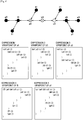
- FIG. 4 is a diagram illustrated to describe an example of topology of nodes in the DC grid and an example of a connection configuration expression as viewed from each node.
- Each node has, for example, a node name, a physical address, an operating mode of DC-to-DC converter, a set current, a set voltage, and so on, as information.
- a branch between nodes has, for example, a branch name, a branch current, and so on, as information.
- An example of the operating mode of DC-to-DC converter includes a mode of supplying power and a mode of receiving power.
- the GM-Agent converts the connection configuration expression with a viewpoint from the particular node set as a starting point into a connection configuration expression with a viewpoint from each node.
- the connection configuration expression with the viewpoint from the node a0 is represented by Expression 1.
- the list of node a0 is taken out from its position and the list of the node b0 in the hierarchy is raised to the previous position of the node a0 so that the list of the node a0 is placed at a position lower than the node b0.
- the connection configuration expression converted to have the viewpoint from the node b0 is represented by Expression 2.
- the GM-Agent can convert the connection configuration expression with the viewpoint from the node b0 into a connection configuration expression created by setting another node c0 as a starting point.
- the connection configuration expression with the viewpoint from the node b0 as represented by Equation 2 can be converted into a connection configuration expression with the viewpoint from the node c0 by taking out the list of the node b0 and raising the list of the node c0 so that the list of the node b0 is placed at a position lower than the node c0.
- the connection configuration expression converted to have the viewpoint from the node c0 is represented by Expression 3.
- connection configuration expression with the viewpoint from the node a0 can be converted into a connection configuration expression with the viewpoint from another node, for example, in FIG. 4 , a node f0 or node a1.
- connection configuration expression represented by Expression 1 For example, to convert the connection configuration expression represented by Expression 1 into a connection configuration expression with a viewpoint from the node f0, the list of node a0 is taken out from its position and the list of the node f0 in the hierarchy is raised to the previous position of the node a0 so that the list of the node a0 is placed at a position lower than the node f0.
- the connection configuration expression converted to have the viewpoint from the node f0 is represented by Expression 4.
- connection configuration expression represented by Expression 1 into a connection configuration expression with a viewpoint from the node a1
- the list of the node a0 is placed at a position lower than the node a1 by replacing the node a0 and the node a1.
- the connection configuration expression converted to have the viewpoint from the node a1 is represented by Expression 5.
- connection configuration expression allows a battery server serving as a master to control the direct-current power to be efficiently transferred using the created connection configuration expression.
- the power in transferring power, the power is discharged or supplied by a plurality of nodes.
- a node that sets the voltage of the DC grid controls the current so that the voltage is maintained by making the total sum of the current flowing out and into the node equal to zero.
- the node that sets the voltage of the DC grid can calculate the sum of current by referring to the connection configuration expression when the current is controlled.
- the GM-Agent of each battery server may function as an example of a power controller according to an embodiment of the present disclosure.
- connection configuration expression created by the activated GM-Agent has been described.
- An exemplary operation of the battery server according to an embodiment of the present disclosure will be described.
- FIGS. 5 to 7 illustrate an exemplary operation of the battery server according to an embodiment of the present disclosure.
- FIGS. 5 and 6 illustrate an exemplary operation of the battery server according to an embodiment of the present disclosure.
- FIGS. 5 to 7 illustrate an exemplary operation in creating a connection configuration expression.
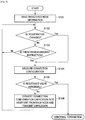
- the GM-Agent of a battery server which obtains a control right by arbitration with another battery server after its starting up, reads the registered node information (step S101).
- the GM-Agent determines whether the registration is changed, more specifically, whether there is a battery server that is newly joined in the DC grid or whether there is a battery server that is withdrawn from the DC grid (step S102).
- the GM-Agent determines whether there is a remeasurement instruction, more specifically, an instruction to measure again the resistance value of the DC grid (step S103).
- the remeasurement instruction may be issued periodically by a trigger based on a timer or may be issued manually by the user.
- step S103 If it is determined, in step S103, that no remeasurement instruction is issued (No in step S103), the GM-Agent returns the process to step S102 to continue to perform the determination process.
- step S104 the GM-Agent measures the connection configuration (step S104).
- the GM-Agent measures the connection configuration to create the connection configuration expression. The measurement of the connection configuration will be described in detail later along with the description with reference to FIG. 6 .
- the GM-Agent determines whether the resistance value in the DC grid is abnormal (step S105).
- the determination of whether the resistance value in the DC grid is abnormal may be made, for example, by determining whether there is a difference between values in which a failure is believed to obviously occur by comparing a currently measured value and a previously measured value.
- step S105 If it is determined, in step S105, that the resistance value in the DC grid is not abnormal (No in step S105), the GM-Agent converts the created connection configuration expression into a connection configuration expression with the viewpoint from each node (battery server) and transmits it to each node (step S106).
- the method of converting the connection configuration expression is as described above.
- step S105 if it is determined, in step S105, that the resistance value in the DC grid is abnormal (Yes in step S105), the GM-Agent does not perform the conversion and transmission of the connection configuration expression, and then the process ends with an abnormal termination.
- the GM-Agent may perform a process for creating any possible alert indicating the occurrence of abnormality.
- the alert may be intended to appeal to the acoustic senses through sound or may be intended to appeal to the visual senses.
- the presentation and contents of the alert are not limited to a particular one.
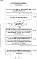
- connection configuration in step S104 will be described in detail with reference to FIG. 6 .
- the GM-Agent instructs all of the DC-to-DC converters (DCCs) capable of receiving the instruction to make the voltage constant and initializes internal data, that is, the connection configuration expression (step S111).
- DCCs DC-to-DC converters
- the GM-Agent retrieves one node from the registered node information (step S112).
- the GM-Agent determines whether there is remaining node information (step S113). If there is any remaining node information (Yes in step S113), the GM-Agent sets one of the DC-to-DC converters associated with a node address to the charge mode, measures the voltage and current values for all of the nodes at that time, and then calculates the resistance value (step S114).
- the GM-Agent When the GM-Agent measures the voltage and current values for all of the nodes and calculates the resistance value, the GM-Agent extracts the connection relationship from the difference in the measured voltage values for all of the nodes and establishes a temporary connection configuration expression (step S115).
- a method of establishing the connection configuration expression is as described above.
- the GM-Agent When the temporary connection configuration expression is established in step S115, the GM-Agent returns the process to the process of step S112 and retrieves other node information. The GM-Agent repeats the process of steps S112 to S115 until no node information is left. If there is no remaining node information (No in step S113), the GM-Agent integrates all of the temporary expressions and calculates the entire connection configuration expression (step S116).
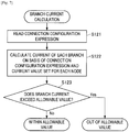
- a process for calculating an electric current flowing through each branch (branch current) will be described with reference to FIG. 7 .
- the GM-Agent when calculating the branch current, reads the connection configuration expression created by the process as described above (step S121).
- the GM-Agent calculates the current of each branch based on the connection configuration expression and the current value set for each node (step S122).
- step S123 the GM-Agent whether the current value of each branch exceeds an allowable value. If it is determined, in step S123, that the current value of each branch does not exceed an allowable value (No in step S123), the GM-Agent performs the process by considering the branch current to be within the allowable value. On the other hand, if it is determined, in step S123, that the current value of each branch exceeds an allowable value (Yes in step S123), the GM-Agent performs the process by considering the branch current to be out of the allowable value.
- “(def (node name) ⁇ (node name) (value) ⁇ )” indicates the command for assigning a current value set with "(value)" to the relevant node.
- the node f0 is set to a current of 6 ampere
- the node g0 is set to a current of 4 ampere
- the node f1 is set to a current of -5 ampere.
- connection configuration expression with the viewpoint from the node a0 is as represented by Expression 1 shown in FIG. 4 , and thus it is found that the node f0 is connected to the nodes f1 and g0.
- the branch current between the nodes f0 and g0 is -4 ampere as viewed from the node f0
- the branch current between the nodes f0 and f1 is 5 ampere as viewed from the node f0
- the calculation of the branch current as described above allows the GM-Agent to prevent a new connection resulting in a case where the current value exceeds a limit value from being established or prevent the new transmission and reception of power resulting in a case where the current value exceeds a limit value from being performed.
- the GM-Agent can block an instruction to perform the transmission and reception of power resulting in a case where the current value exceeds a limit value.
- the activated GM-Agent when measuring the connection configuration, may set the operation of the DC-to-DC converter for each node so that the current flows from a node having a right to control the direct-current bus line 20 (i.e. a node including the activated GM-Agent) to another node for a predetermined time (i.e. to allow the other node to charge a battery).
- a predetermined time i.e. to allow the other node to charge a battery.
- the activated GM-Agent may set the operation of the DC-to-DC converter for each node so that the current flows from a node rather than the node having a control right for a predetermined time.
- the activated GM-Agent sets the operation of the DC-to-DC converter for each node so that the current flows from a node rather than the node having a control right for a predetermined time, and thus it is possible to reduce unilateral loss of power due to the flow of current only from the node having a control right.
- the operation of the DC-to-DC converter may be set by replacing a power transmission node and a power reception node.
- the activated GM-Agent can measure the connection configuration while reducing the unilateral loss of power for each node by replacing discharge and power reception with each other at a node.
- a battery server capable of creating the connection configuration expression relating to the connection topology between nodes by obtaining the voltage value from each node and distributing the generated connection configuration expression to another battery server.
- the battery server creates the connection configuration expression and distributing the created connection configuration expression to another battery server, and thus it is possible to detect timely the connection configuration and to transmit it automatically to each battery server, without the necessity of setting the connection state between nodes for each battery server in advance.
- the battery server In the exchange of power between battery servers, the current flowing through the power line becomes the maximum current value in the state where half of the connected battery servers are discharged at the maximum value and other half of the battery servers are charged at the maximum value.
- the battery server creates the connection configuration expression and distributes the created connection configuration expression other battery servers, and thus it is possible to transmit and receive power efficiently.
- an electric wire having smaller current capacity it is possible to achieve cost reduction in wiring material by devising the transmission control and to achieve cost reduction by capacity reduction in the cut-off breaker for security.
- the battery server creates the connection configuration expression and distributes the created connection configuration expression other battery servers, and thus it is possible to control the power transmission and reception so as not to exceed the allowable value of the DC grid using the connection information.
- the power loss caused by the power transmission line can be calculated in advance, thus it is possible to select an appropriate power transmission destination to transmit power at a higher efficiency and to achieve the efficient exchange of power.
- Steps in processes executed by devices in this specification are not necessarily executed chronologically in the order described in a sequence chart or a flow chart.
- steps in processes executed by devices may be executed in a different order from the order described in a flow chart or may be executed in parallel.
- a computer program can be created which causes hardware such as a CPU, ROM, or RAM, incorporated in each of the devices, to function in a manner similar to that of structures in the above-described devices. Furthermore, it is possible to provide a recording medium having the computer program recorded thereon. Moreover, the hardware configuration of each function block shown in functional block diagrams allows a series of processes to be implemented in hardware.
Description
- The present disclosure relates to a power path information generation device, a method for generating power path information, and computer program.
- There is known an uninterruptible power supply provided with a storage battery for continuing to provide power from the storage battery to equipment connected thereto for a predetermined time without causing power failure even when the power from an input power source is interrupted. Techniques are developed for extending such a power supply into each consumer and supplying power to the consumers when an abnormality occurs in supplying power due to power failure, shortage of storage battery capacity, or other reasons (see
PTLs 1 and 2). - Document
WO2014/072793 A1 states in its abstract an architecture system of a local grid made up of at least two single nodes constituting micro-grids, each managed by a self-configurable node controller that is also connected to the controllers of the other nodes and to the single energy generation, storage and consumption elements of its own node, said elements being variable in their configuration and dynamic in their behaviour; said controller also optimizing the energy transfers according to specific management logics of the routine and sub-routine type. - Xunwei Yu et al:: "Power Management Strategy for plug and play microgrid",XP032332884, and Morstyn Thomas et al: "Cooperative control of DC microgrid storage for energy balancing and equal power sharing", XP032691733, each relate to DC microgrids.
-
- [PTL 1]
JP 2011-205871A - [PTL 2]
JP 2013-090560A - When customers supply power to each other, it is desirable, for the sake of efficiency, to supply direct-current power in consideration of supply of power from a storage battery. When customers supply direct-current power to each other, knowing the connection topology of a node that transmits and receives the direct-current power leads to efficient power transmission. In this case, the connection topology may vary dynamically, and thus information on a changed connection topology for every change in connection topology is necessary to be collected and distributed to each node, which is inefficient.
- Therefore, according to an embodiment of the present disclosure, there is provided a novel and improved power path information generation device, method for generating power path information, and computer program, capable of achieving an efficient transmission of direct-current power by automatically collecting the connection topology of a node that transmits and receives the direct-current power.
- The invention is defined by the independent claims. The dependent claims define advantageous embodiments.
- According to the embodiments of the present disclosure as described above, it is possible to provide a novel and improved power path information generation device, method for generating power path information, and computer program, capable of achieving an efficient transmission of direct-current power by automatically collecting the connection topology of a node that transmits and receives the direct-current power.
- Note that the effects described above are not necessarily limited, and along with or instead of the effects, any effect that is desired to be introduced in the present specification or other effects that can be expected from the present specification may be exhibited.
-
- [
FIG. 1] FIG. 1 is a diagram illustrated to describe an overall configuration example of a power transmission and reception control system according to an embodiment of the present disclosure. - [
FIG. 2] FIG. 2 is a diagram illustrated to describe a functional configuration example of the power transmission and reception control system according to an embodiment of the present disclosure. - [
FIG. 3A] FIG. 3A is a diagram illustrated to describe an example of the created connection configuration expression. - [
Fig.3B]FIG. 3B is a diagram illustrated to describe an example of the created connection configuration expression. - [
Fig.3C] FIG. 3C is a diagram illustrated to describe an example of the created connection configuration expression. - [
Fig.3D]FIG. 3D is a diagram illustrated to describe an example of the created connection configuration expression. - [
Fig.3E]FIG. 3E is a diagram illustrated to describe an example of the created connection configuration expression. - [
Fig.3F] FIG. 3F is a diagram illustrated to describe an example of the created connection configuration expression. - [
Fig.3G]FIG. 3G is a diagram illustrated to describe an example of the created connection configuration expression. - [
Fig.3H]FIG. 3H is a diagram illustrated to describe an example of the created connection configuration expression. - [
Fig.3I]FIG. 3I is a diagram illustrated to describe an example of the created connection configuration expression. - [
Fig.4]FIG. 4 is a diagram illustrated to describe an example of topology of a node in a DC grid and an example of a connection configuration expression as viewed from each node. - [
Fig.5]FIG..5 is an exemplary operation of a battery server according to an embodiment of the present disclosure. - [
Fig.6]FIG. 6 is an exemplary operation of a battery server according to an embodiment of the present disclosure. - [
Fig.7]FIG. 7 is an exemplary operation of a battery server according to an embodiment of the present disclosure. - Hereinafter, preferred embodiments of the present disclosure will be described in detail with reference to the appended drawings. Note that, in this specification and the appended drawings, structural elements that have substantially the same function and structure are denoted with the same reference numerals, and repeated explanation of these structural elements is omitted.
- The description will be made in the following order.
-
- 1.1. Overview
- 1.2. Exemplary System Configuration
- 1.3. Exemplary Operation
- An overview of an embodiment of the present disclosure will be described prior to the description of an embodiment of the present disclosure.
- The description is based on the assumption that an environment becomes increasingly popular in which each consumer is provided with a battery server having a storage battery, the storage battery stores power using a commercial power supply or power generated from a natural energy source such as solar, wind, and geothermal, and the power stored in the storage battery drives electrical appliances. With the spread of such environment, a power interchange system is designed for interchanging power between consumers, as described above. When power is insufficient in a battery server of a consumer, the power interchange system allows a battery server of a consumer having extra power to supply power to the battery server of the consumer having insufficient power. When consumers supply power to each other, it is preferable, for the sake of efficiency, to supply direct-current power in consideration of the supply of power from a storage battery.
- When customers supply direct-current power with each other, it is preferable to previously determine the amount of power transmission exchanged between the power transmission side and the power reception side. The predetermined amount of power is necessary to be properly supplied between the power transmission side and the power reception side. This is because the transmission and reception of the proper amount of power between the power transmission side and the power reception side are necessary to exchange power between the power transmission side and the power reception side.
- When customers supply direct-current power with each other, if the connection topology of each customer (node) is known in advance, it is possible to supply direct-current power with less loss of power transmission. The reasons for this are summarized as follows.
- For example, the existing alternating-current power grid (AC grid) is intended to supply power from a power company to each home in a one-way direction, the distribution wiring is made using power lines that sufficiently withstand the total amount of power consumed in each home. However, as the number of power supply contracts is increased, it becomes necessary to use a material of wiring in consideration of the maximum number of contracts as a power transmission line, which leads to an increased cost.
- As is the case with the AC grid, this is similarly applicable to the direct-current power grid (DC grid). In the case of a DC grid, the flow of current in both directions rather than a single direction and the sequential addition of newly contracted customers are assumed. Thus, in the case of a DC grid, a power transmission line having a constant capacity is desirably used as a power line of home connected to the terminal end, and it is necessary to reduce the cost of a power transmission line by optimizing the maximum transmission power.
- A power cable of at least approximately 50 meters in length may be necessary between home (customers) connected to each other in the DC grid, or some power cables may be up to several hundred meters in length. In such a situation, efficient selection of a power supply destination is necessary to consider power loss that depends on parasitic resistance of the cable. However, the positional relationship between customers is necessary to know to allow for determination of selection of the power supply destination.
- A method of previously checking a connection state by a system administrator in a visual manner, measuring or calculating parasitic resistance value between wires, and re-registering the parasitic resistance value in each device can be considered. However, in a power supply system employing the DC grid as described below, customers can join the system and withdraw from it of their own free will. Thus, it is necessary to check the connection configuration and change a setting whenever customers join the system or withdraw from it.
- Furthermore, for example, even when a failure occurs in a part of the DC grid and a diversion route is set up to separate the part where the failure occurs, it takes time to check the connection configuration again and to set up information on it for each battery server, resulting in difficulties in restoring it in a short time.
- The present inventor has made intensive studies to provide a technology capable of detecting automatically a connection state by a battery server connected to the DC grid and sharing the detected connection state with another battery server. As a result, the present inventor has developed the technology capable of detecting automatically a connection state by a battery server connected to the DC grid and sharing the detected connection state with another battery server as described below.
- An overview of an embodiment of the present disclosure has been described. Next, a functional configuration example of the power transmission and reception control system according to an embodiment of the present disclosure will be described.
-
FIG. 1 is a diagram illustrated to describe an overall configuration example of the power transmission and reception control system according to an embodiment of the present disclosure.FIG. 1 illustrates an overall configuration example of the power transmission and reception control system that interchanges direct-current power between battery servers having their own storage batteries. An overall configuration example of the power transmission and reception control system according to an embodiment of the present disclosure will be described with reference toFIG. 1 . - As shown in
FIG. 1 , the power transmission andreception control system 1 is constructed to mutually supply direct-current power as necessary among battery servers provided in the respective consumers (six inFIG. 1 ). Aconsumer 10a is provided with abattery server 100a. Similarly, aconsumer 10e is provided with abattery server 100e, and aconsumer 10f is provided with abattery server 100f. Each of thebattery servers 100a to 100f has a rechargeable battery provided inside or outside of each battery server. - The
battery servers 100a to 100f are connected to a direct-current bus line 20 over which direct-current power is mutually supplied among the battery servers as necessary. Each of thebattery servers 100a to 100f is provided with a bidirectional DC-to-DC converter that converts voltage of a battery and voltage of the direct-current bus line 20 from one level to another. Thebattery servers 100a to 100f are connected to acommunication wire 30. When thebattery servers 100a to 100f mutually supply direct-current power over the direct-current bus line 20, thebattery servers 100a to 100f transmit and receive information over thecommunication wire 30. Thecommunication wire 30 is illustrated as being wired inFIG. 1 , but thecommunication wire 30 may be wireless. - The
consumers 10a to 10f may be provided withsolar panels 200a to 200f, respectively. Each of thesolar panels 200a to 200f receives irradiation of sunlight and generates electric power. Thesolar panels 200a to 200f are configured so that the generated electric power may be stored in the respective batteries provided in thebattery servers 100a to 100f. The electric power stored in thebattery servers 100a to 100f may be generated by natural energy, such as wind or geothermal, other than sunlight. - The power transmission and
reception control system 1 according to the present embodiment is characterized by a mechanism for arbitrating power transmission and reception among thebattery servers 100a to 100f in such a way that only one of thebattery servers 100a to 100f connected to the direct-current bus line 20 has the right to control the transmission and reception of direct-current power over the direct-current bus line 20. In other words, the power transmission andreception control system 1 according to the present embodiment is configured to have a mechanism that allows only the batter server having the control right among thebattery servers 100a to 100f to instruct other battery servers to transmit power stored in their own batteries or to receive power for charging their own batteries, and that prevents a battery server having no control right from performing the power transmission and reception without permission or instruction. - In this way, only one of the
battery servers 100a to 100f connected to the direct-current bus line 20 has the right to control the transmission and reception of direct-current power to and from other battery servers over the direct-current bus line 20. This makes it possible for the power transmission andreception control system 1 according to the present embodiment to avoid phenomena caused when the roles are simply shared between a master and a slave as described above and to efficiently manage the right to control the power transmission and reception of direct-current power. The power transmission andreception control system 1 according to the present embodiment efficiently manages the right to control the power transmission and reception of direct-current power, thereby keeping the order of objects to be controlled among the battery servers. - The
battery servers 100a to 100f are configured to acquire a current value from anammeter 31 and a voltage value from avoltmeter 32. The current value and the voltage value are measured at the points connected to the direct-current bus line 20. Theammeter 31 and thevoltmeter 32 may be provided in the DC-to-DC converter, which will be described later. Thebattery servers 100a to 100f exchange information on the current value and the voltage value with each other via thecommunication wire 30. Thebattery servers 100a to 100f control their respective bidirectional DC-to-DC converters based on the information on the current value and the voltage value. - An overall configuration example of the power transmission and reception control system according to an embodiment of the present disclosure has been described with reference to
FIG. 1 . Subsequently, a functional configuration example of the power transmission and reception control system according to an embodiment of the present disclosure will be described. -
FIG. 2 is a diagram illustrated to describe a functional configuration example of the power transmission and reception control system according to an embodiment of the present disclosure. A functional configuration example of the power transmission and reception control system according to an embodiment of the present disclosure will be described with reference toFIG. 2 . - As shown in
FIG. 2 , thebattery server 100a is configured to include a U-Agent 110a, an M-Agent 120a, a GM-Agent 130a, a C-Agent 140a, a DC-to-DC converter 150a, and abattery 160a. Thebattery servers battery server 100a. The components that constitute thebattery server 100a will be described. - As described in
FIG. 2 , thecommunication wire 30 is composed of two paths (channels) including acommunication wire 30a and acommunication wire 30b. Thecommunication wires FIG. 2 , thecommunication wire 30a allows the U-Agent 110a to communicate with other U-Agents 110b to 110d, and the M-Agent 120a to communicate with other M-Agents 120b to 120d. Thecommunication wire 30b allows the GM-Agent 130a to communicate with other GM-Agents 130b to 130d, and the C-Agent 140a to communicate with other C-Agents 140b to 140d. - The power transmission and
reception control system 1 according to the present embodiment uses separate communication wires for the U-Agent 110a and the M-Agent 120a and for the GM-Agent 130a and the C-Agent 140a. As a result, theU-Agent 110a and the M-Agent 120a are prevented from directly sending an instruction to the GM-Agent 130a and the C-Agent 140a. The GM-Agent 130a and the C-Agent 140a are also prevented from directly sending an instruction to theU-Agent 110a and the M-Agent 120a. - The
U-Agent 110a periodically checks the state of charge (SOC) in thebattery 160a. If the state of charge in thebattery 160a satisfies a predetermined condition, theU-Agent 110a requests the M-Agent 120a to receive power. The request to be sent from the U-Agent 110a to the M-Agent 120a may include a voltage value or current value upon reception of power, a time for receiving power (e.g., start time, end time, and duration), and a state of charge in thebattery 160a that stops receiving power. - The U-Agent 110a refers to a
scenario 170a to determine whether the state of charge in thebattery 160a satisfies a predetermined condition. Thescenario 170a describes a condition of the state of charge in thebattery 160a, which is used to request the M-Agent 120a to receive power from theU-Agent 110a. The condition described in thescenario 170a may include contents of the U-Agent 110a requesting the M-Agent 120a to receive power if the state of charge in thebattery 160a is lower than or equal to 20%. - The
U-Agent 110a may have a function that edits contents of thescenario 170a based on the request from the user. The contents of thescenario 170a may be described in text, a markup language such as extensible markup language (XML), or a scripting language such as Lisp, Perl, and PHP. When the contents of thescenario 170a are described in a scripting language, the contents of thescenario 170a may be described in a set of functions. - The
scenario 170a may be edited using a text editor, a dedicated editor, or a web browser. TheU-Agent 110a may be configured so that a tool capable of editing the contents of thescenario 170a is operable. - When there is a request for supply of power from another battery server, the
scenario 170a may describe a way of determining whether power transmission is permitted in response to the request depending on what condition is satisfied. For example, when there is a request for supply of power from another battery server, thescenario 170a may describe contents in which power transmission is permitted in response to the request under the condition that the state of charge in thebattery 160a is greater than or equal to 80%. For example, when there is a request for supply of power from another battery server, thescenario 170a may describe contents in which power transmission is permitted in response to the request under the condition that the state of charge in thebattery 160a is greater than or equal to 80% and the usage rate per hour of the power is less than or equal to 10%. In other words, the condition described in thescenario 170a may include not only the state of charge in thebattery 160a but also the state of usage of electric power stored in thebattery 160a. - The contents of the scenario are possible to be defined independently at the respective batteries. Accordingly, the condition in which power reception is requested or the condition in which power transmission is permitted in response to a request for supply of power from another battery server may be different for each battery server. The number of scenarios to be defined at each battery server is not limited to only one. The scenario referred to by the
U-Agent 110a may be switched into another, depending on the situation. - When the M-
Agent 120a receives a request for power reception from theU-Agent 110a, the M-Agent 120a inquires of the M-Agents Agents communication wire 30a. When the M-Agent 120a receives an inquiry about whether the M-Agent 120a is allowed to transmit power from the M-Agents Agent 120a responds that power is allowed to be transmitted or not. - When the M-
Agent 120a receives an inquiry as to whether the M-Agent 120a is allowed to transmit power from the M-Agents Agent 120a may respond that power is allowed to be transmitted. In this case, if the GM-Agent 130a is not started, the M-Agent 120a inquires of the M-Agents Agents communication wire 30a. As will be described in detail later, the GM-Agent 130a is started based on the start instruction from the M-Agent 120a and controls the operation of the DC-to-DC converters 150a to 150d of the battery servers. - In the power transmission and
reception control system 1 according to the present embodiment, only one of the GM-Agents 130a to 130d is permitted to start. Thus, when the GM-Agent 130a is not started, the M-Agent 120a determines that thebattery server 100a does not have the right to control the power transmission and reception and inquires of the M-Agents communication wire 30a. If there is a GM-Agent being started, the M-Agent 120a requests the GM-Agent being started to transmit and receive power through the M-Agent that causes the GM-Agent to start. For example, if the GM-Agent 130b is being started, the M-Agent 120a requests the M-Agent 120b to transmit and receive power through the M-Agent 120b. - On the other hand, if there is an inquiry about whether the power transmission is possible or not from the M-
Agents Agent 130a is started, the fact that the GM-Agent 130a is started is responded together. - The M-
Agent 120a notifies the C-Agent 140a to follow an instruction only from a GM-Agent of the battery server having a control right. For example, the M-Agent 120a notifies identification information, which identifies a GM-Agent of the battery server having a control right, to the C-Agent 140a. when the C-Agent 140a receives the notification of identification information that identifies a GM-Agent of the battery server having a control right, the C-Agent 140a may ignore an instruction from a GM-Agent that contains identification information other than the identification information. - The GM-
Agent 130a is started and activated according to a start instruction from the M-Agent 120a. The GM-Agent 130a is stopped and deactivated according to a stop instruction from the M-Agent 120a. The activated GM-Agent 130a controls the power transmission and reception by the DC-to-DC converters 150a to 150d through the C-Agents 140a to 140d over thecommunication wire 30b based on the request for the power transmission and reception from the M-Agents 120a to 120d. When the requested power transmission and reception is all ended, the GM-Agent 130a performs a process for releasing the control right. When the control right is released, the GM-Agent 130a is stopped and deactivated according to the stop instruction from the M-Agent 120a. - When there is a request for the power transmission and reception from the M-
Agents 120a to 120d, the GM-Agent 130a acquires the power transmission capacity and power reception capacity of therespective battery servers 100a to 100d from the C-Agents 140a to 140d over thecommunication wire 30b. The GM-Agent 130a also calculates an amount of electric current that can be transmitted, from the total transmission current amount of the direct-current bus line 20. When the accumulated power transmission amount reaches a desired power transmission amount after power transmission is started, the GM-Agent 130a instructs the C-Agents 140a to 140d to stop transmitting power over thecommunication wire 30b. - The C-
Agent 140a controls the DC-to-DC converter 150a based on an instruction from the activated (i.e. having a control right) GM-Agent among the GM-Agents 130a to 130d. The C-Agent 140a receives the notification from the M-Agent 120a to follow the instruction only from the GM-Agent of the battery server having the control right. Thus, the C-Agent 140a controls the DC-to-DC converter 150a according to the instruction only from the GM-Agent of the battery server having the control right. - The C-
Agent 140a periodically checks a parameter of the DC-to-DC converter 150a, and warns a target transmitter or receiver of power upon occurrence of an abnormality in the parameter of the DC-to-DC converter 150a. - The DC-to-
DC converter 150a is connected between thebattery 160a or thesolar panel 200a and alocal bus line 21a, and is connected to the DC-to-DC converters 150b to 150d of theother battery servers 100b to 100d over the direct-current bus line 20. The DC-to-DC converter 150a converts a direct-current power between the direct-current bus line 20 and thelocal bus line 21a under the control by the C-Agent 140a. - The
U-Agent 110a operates according to thescenario 170a defined independently in therespective battery servers 100a to 100d. The M-Agent 120a, the GM-Agent 130a, and the C-Agent 140a operate according to acommon policy 180 to all of thebattery servers 100a to 100d. Thus, the M-Agent 120a, the GM-Agent 130a, and the C-Agent 140a are not allowed to operate according to different rules of theother battery servers 100b to 100d. - The contents of the
policy 180 may be described in a text, a markup language such as extensible markup language (XML), or a scripting language such as Lisp, Perl, and PHP. When the contents of thepolicy 180 are described in a scripting language, the contents of thescenario 170a may be described in a set of functions. - The
policy 180 may be edited using a text editor, a dedicated editor, or a web browser. As described above, thepolicy 180 is commonly referred to by all of thebattery servers 100a to 100d, and thus it is desirable that the user is unable to edit easily, but it may be possible that the user can edit as necessary. The M-Agent 120a, the GM-Agent 130a, or the C-Agent 140a may edit thepolicy 180 based on the rule defined in thepolicy 180. - Examples of the contents described in the
scenario 170a may include as follows: - State of charge (SOC) level to request supply of power
- SOC level to determine that power is able to be supplied
- Method of predicting and calculating battery residual amount with power consumption cycle in a day
- Technique of predicting and calculating power generation amount in a week depending on acquisition of weather information
- Calculation of reduction in AC power usage depending on power interchange
- Examples of the contents described in the
policy 180 may include a document version, date of modification, rule in modifying described contents, and respective rules defined for the M-Agents 120a to 120d, the GM-Agents 130a to 130d, and the C-Agents 140a to 140d. - Examples of rules defined for the M-
Agents 120a to 120d may include as follows: - Determination condition and decision procedure for acquiring control right
- Decision procedure for appeal from other devices
- Procedure of checking survival of battery server joined in the power transmission and
reception control system 1 - Procedure of deleting registration of battery server previously joined in the power transmission and
reception control system 1 - List and authentication information of members joined in the power transmission and
reception control system 1 - Examples of the determination condition for acquiring a control right may include a condition in which a control right can be acquired if there is even one M-Agent being in favor and a condition in which a control right can be acquired if a majority is in favor. Examples of the decision procedure for acquiring a control right may include a decision procedure in which a command is transmitted to other M-Agents in broadcast mode to acquire a control right and whether the control right is acquired is determined based on the response from the other M-Agent that returned an answer in a predetermined time. Similarly, examples of the decision procedure for appeal from other devices may include a decision procedure in which a command is transmitted to other M-Agents to acquire a control right and whether the control right is acquired is determined based on the contents of appeal from the other M-Agent that returned an answer in a predetermined time.
- Examples of the procedure of checking survival of a battery server joined in the power transmission and
reception control system 1 may include an example where the M-Agent of the battery server which is the last one to acquire a control right checks whether other battery servers are survived. - Examples of the procedure of deleting registration of a battery server previously joined in the power transmission and
reception control system 1 may include a procedure of deleting registration information described in thepolicy 180 based on the command for requesting the deletion. - The list and authentication information of members joined in the power transmission and
reception control system 1 are described in thepolicy 180, and thus the M-Agent can transmit various command only to the joined member and can add authentication information upon transmission of the command. Examples of the authentication information of a member may include address information of each battery server and an authentication key that is common to the battery servers. - Examples of rules defined for the GM-
Agents 130a to 130d may include as follows: - Information on connection state of battery servers as viewed from their position
- Method of calculating current capacity based on information on connection state of each battery server
- Control procedure and limitations of DC-DC converter
- Procedure from start to end for power transmission and reception in each battery server
- Abandonment or transfer procedure of control right after supply of power is stopped
- Processing procedure when abnormality is notified
- The direct-current power flows in the direct-
current bus line 20, and thus the GM-Agents 130a to 130d are necessary to know the connection state of thebattery servers 100a to 100d to the direct-current bus line 20 and to determine how to supply power based on position information of thebattery servers 100a to 100d. The connection state of thebattery servers 100a to 100d to the direct-current bus line 20 is described in thepolicy 180, and thus the GM-Agents 130a to 130d refer to the connection state to control the DC-to-DC converters 150a to 150d. - Examples of the procedure of controlling a DC-to-DC converter may include contents of an instruction sent to the DC-to-DC converter when direct-current power is converted. Examples of the limitations of a DC-to-DC converter may include a range in which power can be converted.
- Examples of the procedure from start to end for power transmission and reception in each battery server may include a procedure of increasing electric current at the start of the power transmission or reception and a procedure of decreasing electric current at the end of the power transmission or reception.
- Examples of the abandonment or transfer procedure of a control right after supply of power is stopped may include a procedure in which, for example, if there is another battery server that supplies power, the control right is transferred to the other battery server.
- Examples of the processing procedure when abnormality is notified may include a procedure in which, if a batter server has a failure, the failed battery server is ignored and the processing proceeds.
- Examples of rules defined for the C-
Agents 140a to 140d may include as follows: - Procedure of checking whether it is continued to be controlled by a GM-Agent of a battery server having the control right and processing procedure upon occurrence of abnormality
- Procedure of checking whether it is controlled simultaneously by a plurality of GM-Agents
- Processing procedure when it is controlled simultaneously by a plurality of GM-Agents
- Monitoring procedure of checking operations of a DC-to-DC converter and appropriately notifying the check results to a GM-Agent of a battery server having the control right
- Examples of the procedure of checking whether it is continued to be controlled by a GM-Agent of a battery server having a control right may include a procedure of checking whether it is controlled by the GM-Agent at predetermined time intervals. Examples of the processing procedure upon occurrence of abnormality may include a procedure of notifying the GM-Agent of a battery server having a control right that control by the GM-Agent is interrupted for more than a predetermined time.
- Examples of the procedure of checking whether it is controlled simultaneously by a plurality of GM-Agents may include a procedure of checking whether it is controlled by a GM-Agent having identification information different from that notified from the M-Agent. Examples of the processing procedure when it is controlled simultaneously by a plurality of GM-Agents may include a procedure of ignoring the control by the GM-Agent having identification information different from that notified from the M-Agent and notifying a GM-Agent of a battery server having a control right that it is controlled simultaneously by a plurality of GM-Agents by dealing with the control from all of the GM-Agents as errors.
- Examples of the monitoring procedure of checking operations of a DC-to-DC converter and appropriately notifying the check results to a GM-Agent of a battery server having the control right may include a procedure of checking a parameter of a DC-to-DC converter at predetermined time intervals and notifying a parameter of the DC-to-DC convert to a GM-Agent of a battery server having the control right.
- The
policy 180 defined as described above allows the C-Agents 140a to 140d to send an instruction to stop transmitting power to the DC-to-DC converters 150a to 150d immediately when the instruction from the GM-Agent violates the contents of thepolicy 180. - The description contents of the
above scenario 170a or thepolicy 180 and examples of the description contents of theabove scenario 170a or thepolicy 180 are not limited to those described above. The description contents of thescenario 170a or thepolicy 180 may be appropriately changed depending on the configuration of the power transmission andreception control system 1 or the configuration of each of thebattery servers 100a to 100d. - The
battery 160a is composed of a rechargeable secondary battery. Thebattery 160a may be charged with power generated by thesolar panel 200a or power supplied from the commercial supply of power (not shown). Thebattery 160a may be charged with power supplied fromother battery servers 100b to 100d as necessary. The power stored in thebattery 160a may be supplied to electric appliances such as air conditioner, refrigerator, washing machine, television set, and microwave, provided in theconsumer 10a. The power stored in thebattery 160a may be supplied from the DC-to-DC converter 150a toother battery servers 100b to 100d depending on the request from theother battery servers 100b to 100d. - The
battery servers 100a to 100d according to an embodiment of the present disclosure have the configuration as shown inFIG. 2 , and thus only one battery server of them having a control right can control power transmission and reception of direct-current power to and from the other battery servers over the direct-current bus line 20. Thebattery servers 100a to 100d according to an embodiment of the present disclosure have the configuration as shown inFIG. 2 , and thus it is possible to avoid phenomena caused when the roles are simply shared between a master and a slave as described above and to efficiently manage the right to control the power transmission and reception of direct-current power. Thebattery servers 100a to 100d according to an embodiment of the present disclosure have the configuration as shown inFIG. 2 , and thus it is possible to efficiently manage the right to control the power transmission and reception of direct-current power, thereby keeping the order of objects to be controlled among the battery servers. - The direct-
current bus line 20 or thelocal bus lines 21a to 21d are not limited to the particular configuration. For example, the direct-current bus line 20 or thelocal bus lines 21a to 21d may be configured as a direct-current single-phase three-wire bus line having two lines supplied with positive voltage and negative voltage, and a line connected to the ground. - In the present embodiment, the GM-Agent of a battery server having a control right detects how each of the battery servers is connected to the direct-
current bus line 20 using resistance components R12, R23, R34, R45, ... depending on the thickness and length of a power cable used as the direct-current bus line 20. Although a specific processing procedure will be described in detail later, an overview thereof is described below. - The GM-Agent of a battery server, which has a control right, issues an instruction of charge or discharge to another battery server via the
communication wire 30. This instruction is issued to the DC-to-DC converter through the C-Agent of the other battery server via thecommunication wire 30. The GM-Agent of the battery server having a control right reads the voltage value and current value from all of the DC-to-DC converters through the C-Agent 140a delivering the instruction, and estimates a connection state based on the amount of voltage drop to derive the connection configuration from the read voltage value and electric current value. - Similarly for other battery servers, the GM-Agent of a battery server, which has a control right, issues an instruction of charge or discharge to the DC-to-DC converter through the C-Agent of the other battery server. The GM-Agent then obtains the voltage value and current value by reading them from the DC-to-DC converter to derive the connection configuration. The GM-Agent repeats this process until all of the connection configuration expressions are completed.
- The connection configuration expressions completed by the activated GM-Agent (having a control right) become a connection configuration as viewed from the activated GM-Agent. Thus, the GM-Agent converts the connection configuration expressions to match the position of each of the battery servers and then transmits the converted connection configuration expressions to the respective battery servers. The battery server registers the connection configuration expression transmitted from the activated GM-Agent. Thus, the DC-to-DC converter in each of the battery servers may function as one example of a voltage variation information acquisition unit according to an embodiment of the present disclosure. The activated GM-Agent may function as one example of a path information generation unit according to an embodiment of the present disclosure.
- In some cases, a battery server is not connected to the direct-
current bus line 20 or a battery server is unable to communicate, for example, due to trouble in a network. In these cases, it is not possible to acquire the voltage value and current value. Thus, the activated GM-Agent creates the connection configuration expression on the assumption that there is no such battery server. - An example of the connection configuration expression created by the activated GM-Agent will be described.
FIGS. 3A to 3I are diagrams illustrated to describe an example of the connection configuration expression created by the activated GM-Agent. - The connection configuration expression (S-expression) represents the topology of nodes. The S-expression indicates the name of a node and the connection relationship between the node and a subsequent node. The symbol "()" following a node indicates that the node is the termination.
- When the connection configuration expression is created, the GM-Agent sets a node to a positive voltage source and sets another node to a negative voltage source. The voltage values of all of the nodes being recognized are measured through the power supply from the positive voltage source.
- In the connection configuration expression according to the present embodiment, nodes having the same potential as a reference node are placed at a list of the same level, and nodes having a potential lower than the reference node are placed at a sub-list. The connection configuration expression according to the present embodiment is produced as a connection configuration expression of a sub-list in descending order of potential. A node, which has a voltage lower than a reference node and has a higher voltage than the electric current source, is borrowed by carrying with a symbol (*), and then is set to the electric current source and its voltage is re-checked.
- The present embodiment is based on the assumption that the DC grid has a loop-free configuration.
-
FIG. 3A is the simplest example and illustrates an example of a case where the GM-Agent creates a connection configuration expression for two nodes N1 and N2. If the nodes N1 and N2 are set to a voltage of Vn1 and Vn2, respectively, and as a result of measuring them, the relationship of Vn1 > Vn2 is established, the GM-Agent sets the connection configuration expression as follows:
(n1 (n2 ())) -
FIG. 3B illustrates an example of a case where the GM-Agent creates a connection configuration expression for three nodes N1, N2, and N3. If the nodes N1, N2, and N3 are set to a voltage of Vn1, Vn2, and Vn3, respectively, and as a result of measuring them, the relationship of Vn1 > Vn2 and Vn1 = Vn3 is established, the GM-Agent sets the connection configuration expression as follows:
(n1 (n2 ()) (n3*)) -
FIG. 3C illustrates an example of a case where the GM-Agent creates a connection configuration expression for three nodes N1, N2, and N3. If the nodes N1, N2, and N3 are set to a voltage of Vn1, Vn2, and Vn3, respectively and as a result of measuring them, the relationship of Vn1 > Vn3 and Vn2 = Vn3 is established, the GM-Agent sets the connection configuration expression as follows:
(n1 (n3 n2*)) -
FIG. 3D illustrates an example of a case where the GM-Agent creates a connection configuration expression for three nodes N1, N2, and N3. If the nodes N1, N2, and N3 are set to a voltage of Vn1, Vn2, and Vn3, respectively and as a result of measuring them, the relationship of Vn1 > Vn2 > Vn3 is established, the GM-Agent sets the connection configuration expression as follows:
(n1 (n2 (n3 ()))) - In this way, when the GM-Agent creates a connection configuration expression for three nodes N1, N2, and N3, the voltage is measured by setting the node N1 as a starting point and by setting the nodes N2 and N3 as a current sink. However, they may be sequentially replaced with a current source to prevent the power from being consumed unilaterally. In other words, if the GM-Agent specifies the node N1 as a current source in the initial measurement, the GM-Agent may specify the node N2 as a current source in the subsequent measurement and specify the node N3 as a current source in the next subsequent measurement. In this case, the GM-Agent is preferable to allow each node to absorb the current so that the power transfer between nodes upon the measurement of voltage is equal to each other as much as possible.
- An example of creating the connection configuration expression for three nodes has been described. An example of creating a connection configuration expression for four nodes will be described.
-
FIG. 3E illustrates an example of a case where the GM-Agent creates a connection configuration expression for four nodes N1, N2, N3, and N4. If the nodes N1, N2, N3, and N4 are set to a voltage of Vn1, Vn2, Vn3, and Vn4, respectively, and as a result of measuring them, the relationship of Vn1 > Vn2 and Vn1 = Vn3 = Vn4 is established, the GM-Agent sets the connection configuration expression as follows:
(n1 (n2 ()) n3* n4*) -
FIG. 3F illustrates an example of a case where the GM-Agent creates a connection configuration expression for four nodes N1, N2, N3, and N4. If the nodes N1, N2, N3, and N4 are set to a voltage of Vn1, Vn2, Vn3, and Vn4, respectively, and as a result of measuring them, the relationship of Vn1 > Vn2 and Vn2 = Vn3 = Vn4 is established, the GM-Agent sets the connection configuration expression as follows:
(n1 (n2 n3* n4*)) -
FIG. 3G illustrates an example of a case where the GM-Agent creates a connection configuration expression for four nodes N1, N2, N3, and N4. If the nodes N1, N2, N3, and N4 are set to a voltage of Vn1, Vn2, Vn3, and Vn4, respectively, and as a result of measuring them, the relationship of Vn1 > Vn2 > Vn4 and Vn2 = Vn3 is established, the GM-Agent sets the connection configuration expression as follows:
(n1 (n2 (n4 ())) n3) - An example of creating the connection configuration expression for four nodes has been described. An example of creating a connection configuration expression for five nodes will be described.
-
FIG. 3H illustrates an example of a case where the GM-Agent creates a connection configuration expression for five nodes N1, N2, N3, N4, and N5. If the nodes N1, N2, N3, N4, and N5 are set to a voltage of Vn1, Vn2, Vn3, Vn4, and Vn5, respectively, and as a result of measuring them, the relationship of Vn1 > Vn2 > Vn4 and Vn2 = Vn3 = Vn5 is established, the GM-Agent sets the connection configuration expression as follows:
(n1 (n2 (n4 ())) n3* n5*) -
FIG. 3I illustrates an example of a case where the GM-Agent creates a connection configuration expression for five nodes N1, N2, N3, N4, and N5. If the nodes N1, N2, N3, N4, and N5 are set to a voltage of Vn1, Vn2, Vn3, Vn4, and Vn5, respectively, and as a result of measuring them, the relationship of Vn1 > Vn3 > Vn5 and Vn1 = Vn2 = Vn4 is established, the GM-Agent sets the connection configuration expression as follows:
(n1 (n2 (n4 ())) (n3 (n5 ()))) - In this way, even when the number of nodes is increased, the GM-Agent can create a connection configuration expression from the voltage value of each node.
- The connection configuration expression provided as described above is created with a viewpoint from a particular node. In the examples described above, all of the viewpoints are taken from the node N1. The GM-Agent converts the connection configuration expression with the viewpoint from the particular node into a connection configuration expression with a viewpoint from each node, and then distributes it to each node.
-
FIG. 4 is a diagram illustrated to describe an example of topology of nodes in the DC grid and an example of a connection configuration expression as viewed from each node. - Each node has, for example, a node name, a physical address, an operating mode of DC-to-DC converter, a set current, a set voltage, and so on, as information. A branch between nodes has, for example, a branch name, a branch current, and so on, as information. An example of the operating mode of DC-to-DC converter includes a mode of supplying power and a mode of receiving power.
- When a connection configuration expression is created by setting a node as a starting point, the GM-Agent converts the connection configuration expression with a viewpoint from the particular node set as a starting point into a connection configuration expression with a viewpoint from each node. For example, in the example shown in
FIG. 4 , the connection configuration expression with the viewpoint from the node a0 is represented byExpression 1. To convert the connection configuration expression represented byExpression 1 into a connection configuration expression with a viewpoint from the node b0, the list of node a0 is taken out from its position and the list of the node b0 in the hierarchy is raised to the previous position of the node a0 so that the list of the node a0 is placed at a position lower than the node b0. The connection configuration expression converted to have the viewpoint from the node b0 is represented byExpression 2. - The GM-Agent can convert the connection configuration expression with the viewpoint from the node b0 into a connection configuration expression created by setting another node c0 as a starting point. For example, in the example shown in
FIG. 4 , the connection configuration expression with the viewpoint from the node b0 as represented byEquation 2 can be converted into a connection configuration expression with the viewpoint from the node c0 by taking out the list of the node b0 and raising the list of the node c0 so that the list of the node b0 is placed at a position lower than the node c0. The connection configuration expression converted to have the viewpoint from the node c0 is represented byExpression 3. - Similarly, the connection configuration expression with the viewpoint from the node a0 can be converted into a connection configuration expression with the viewpoint from another node, for example, in
FIG. 4 , a node f0 or node a1. - For example, to convert the connection configuration expression represented by
Expression 1 into a connection configuration expression with a viewpoint from the node f0, the list of node a0 is taken out from its position and the list of the node f0 in the hierarchy is raised to the previous position of the node a0 so that the list of the node a0 is placed at a position lower than the node f0. The connection configuration expression converted to have the viewpoint from the node f0 is represented byExpression 4. - In addition, for example, to convert the connection configuration expression represented by
Expression 1 into a connection configuration expression with a viewpoint from the node a1, the list of the node a0 is placed at a position lower than the node a1 by replacing the node a0 and the node a1. The connection configuration expression converted to have the viewpoint from the node a1 is represented byExpression 5. - The creation of a connection configuration expression as described above allows a battery server serving as a master to control the direct-current power to be efficiently transferred using the created connection configuration expression. In other words, in transferring power, the power is discharged or supplied by a plurality of nodes. In this case, a node that sets the voltage of the DC grid controls the current so that the voltage is maintained by making the total sum of the current flowing out and into the node equal to zero. The node that sets the voltage of the DC grid can calculate the sum of current by referring to the connection configuration expression when the current is controlled. Thus, the GM-Agent of each battery server may function as an example of a power controller according to an embodiment of the present disclosure.
- An example of the connection configuration expression created by the activated GM-Agent has been described. An exemplary operation of the battery server according to an embodiment of the present disclosure will be described.
-
FIGS. 5 to 7 illustrate an exemplary operation of the battery server according to an embodiment of the present disclosure. InFIGS. 5 to 7 , an exemplary operation of the battery server according to an embodiment of the present disclosure in creating a connection configuration expression and in calculating each branch current. - An exemplary operation in creating a connection configuration expression will be described.
FIGS. 5 and6 illustrate an exemplary operation of the battery server according to an embodiment of the present disclosure.FIGS. 5 to 7 illustrate an exemplary operation in creating a connection configuration expression. - The overall procedure will be described with reference to
FIG. 5 . The GM-Agent of a battery server, which obtains a control right by arbitration with another battery server after its starting up, reads the registered node information (step S101). When the GM-Agent reads the registered node information, the GM-Agent determines whether the registration is changed, more specifically, whether there is a battery server that is newly joined in the DC grid or whether there is a battery server that is withdrawn from the DC grid (step S102). - If it is determined, in step S102, that no registration is changed (No in step S102), the GM-Agent determines whether there is a remeasurement instruction, more specifically, an instruction to measure again the resistance value of the DC grid (step S103). The remeasurement instruction may be issued periodically by a trigger based on a timer or may be issued manually by the user.
- If it is determined, in step S103, that no remeasurement instruction is issued (No in step S103), the GM-Agent returns the process to step S102 to continue to perform the determination process.
- On the other hand, if it is determined, in step S102, that the registration is changed (Yes in step S102) or if it is determined, in step S103, that the remeasurement instruction is issued (Yes in step S103), the GM-Agent measures the connection configuration (step S104). The GM-Agent measures the connection configuration to create the connection configuration expression. The measurement of the connection configuration will be described in detail later along with the description with reference to
FIG. 6 . - When the GM-Agent performs the measurement of the connection configuration, the GM-Agent determines whether the resistance value in the DC grid is abnormal (step S105). The determination of whether the resistance value in the DC grid is abnormal may be made, for example, by determining whether there is a difference between values in which a failure is believed to obviously occur by comparing a currently measured value and a previously measured value.
- If it is determined, in step S105, that the resistance value in the DC grid is not abnormal (No in step S105), the GM-Agent converts the created connection configuration expression into a connection configuration expression with the viewpoint from each node (battery server) and transmits it to each node (step S106). The method of converting the connection configuration expression is as described above.
- On the other hand, if it is determined, in step S105, that the resistance value in the DC grid is abnormal (Yes in step S105), the GM-Agent does not perform the conversion and transmission of the connection configuration expression, and then the process ends with an abnormal termination. When the resistance value in the DC grid is abnormal, the GM-Agent may perform a process for creating any possible alert indicating the occurrence of abnormality. The alert may be intended to appeal to the acoustic senses through sound or may be intended to appeal to the visual senses. The presentation and contents of the alert are not limited to a particular one.
- The measurement process procedure of the connection configuration in step S104 will be described in detail with reference to
FIG. 6 . - The GM-Agent instructs all of the DC-to-DC converters (DCCs) capable of receiving the instruction to make the voltage constant and initializes internal data, that is, the connection configuration expression (step S111).
- Then, the GM-Agent retrieves one node from the registered node information (step S112). When the GM-Agent retrieves one node from the registered node information, the GM-Agent determines whether there is remaining node information (step S113). If there is any remaining node information (Yes in step S113), the GM-Agent sets one of the DC-to-DC converters associated with a node address to the charge mode, measures the voltage and current values for all of the nodes at that time, and then calculates the resistance value (step S114).
- When the GM-Agent measures the voltage and current values for all of the nodes and calculates the resistance value, the GM-Agent extracts the connection relationship from the difference in the measured voltage values for all of the nodes and establishes a temporary connection configuration expression (step S115). A method of establishing the connection configuration expression is as described above.
- When the temporary connection configuration expression is established in step S115, the GM-Agent returns the process to the process of step S112 and retrieves other node information. The GM-Agent repeats the process of steps S112 to S115 until no node information is left. If there is no remaining node information (No in step S113), the GM-Agent integrates all of the temporary expressions and calculates the entire connection configuration expression (step S116).
- A process for calculating an electric current flowing through each branch (branch current) will be described with reference to
FIG. 7 . The GM-Agent, when calculating the branch current, reads the connection configuration expression created by the process as described above (step S121). - When the connection configuration expression is read in step S121, the GM-Agent calculates the current of each branch based on the connection configuration expression and the current value set for each node (step S122).
- When the current of each branch is calculated in step S122, the GM-Agent whether the current value of each branch exceeds an allowable value (step S123). If it is determined, in step S123, that the current value of each branch does not exceed an allowable value (No in step S123), the GM-Agent performs the process by considering the branch current to be within the allowable value. On the other hand, if it is determined, in step S123, that the current value of each branch exceeds an allowable value (Yes in step S123), the GM-Agent performs the process by considering the branch current to be out of the allowable value.
- A method of calculating the current of each branch based on the connection configuration expression and the current value set for each node will be described. For example, in a case where each node of the DC grid is connected as shown in
FIG. 4 , the current value of each node is assumed to be set by the GM-Agent, as follows: - (def a0 {:a0 0})
- (def a1 {:a1 - 1})
- (def b0 {:b0 2})
- (def c0 {:c0 -3})
- (def c1 {:c1 4})
- (def d0 {:d0 -5})
- (def d1 {:d1 6})
- (def e0 {:e0 -7})
- (def f0 {:f0 6})
- (def f1 {:f1 -5})
- (def g0 {:g0 4})
- In the above, "(def (node name) {(node name) (value)})" indicates the command for assigning a current value set with "(value)" to the relevant node. In other words, in the command, for example, the node f0 is set to a current of 6 ampere, the node g0 is set to a current of 4 ampere, and the node f1 is set to a current of -5 ampere.
- In this case, the connection configuration expression with the viewpoint from the node a0 is as represented by
Expression 1 shown inFIG. 4 , and thus it is found that the node f0 is connected to the nodes f1 and g0. Thus, if the branch current between the nodes f0 and g0 is -4 ampere as viewed from the node f0 and the branch current between the nodes f0 and f1 is 5 ampere as viewed from the node f0, the GM-Agent can calculate that the branch current between the nodes a0 and f0 is 5 ampere (-(4 - 5 + 6) = -5) as viewed from the node a0. - The calculation of the branch current as described above allows the GM-Agent to prevent a new connection resulting in a case where the current value exceeds a limit value from being established or prevent the new transmission and reception of power resulting in a case where the current value exceeds a limit value from being performed. In other words, the GM-Agent can block an instruction to perform the transmission and reception of power resulting in a case where the current value exceeds a limit value.
- The activated GM-Agent, when measuring the connection configuration, may set the operation of the DC-to-DC converter for each node so that the current flows from a node having a right to control the direct-current bus line 20 (i.e. a node including the activated GM-Agent) to another node for a predetermined time (i.e. to allow the other node to charge a battery). However, when the GM-Agent measures the connection configuration, the relationship of voltage drop and the resistance value between nodes may be preferable to be separated from each other. Thus, the activated GM-Agent may set the operation of the DC-to-DC converter for each node so that the current flows from a node rather than the node having a control right for a predetermined time.
- In this way, the activated GM-Agent sets the operation of the DC-to-DC converter for each node so that the current flows from a node rather than the node having a control right for a predetermined time, and thus it is possible to reduce unilateral loss of power due to the flow of current only from the node having a control right.
- Furthermore, when the activated GM-Agent sets the operation of the DC-to-DC converter for each node so that the current flows from a node to another node for a predetermined time in measuring the connection configuration, the operation of the DC-to-DC converter may be set by replacing a power transmission node and a power reception node. The activated GM-Agent can measure the connection configuration while reducing the unilateral loss of power for each node by replacing discharge and power reception with each other at a node.
- According to an embodiment of the present disclosure as described above, there is provided a battery server capable of creating the connection configuration expression relating to the connection topology between nodes by obtaining the voltage value from each node and distributing the generated connection configuration expression to another battery server.
- The battery server according to an embodiment of the present disclosure creates the connection configuration expression and distributing the created connection configuration expression to another battery server, and thus it is possible to detect timely the connection configuration and to transmit it automatically to each battery server, without the necessity of setting the connection state between nodes for each battery server in advance.
- In the exchange of power between battery servers, the current flowing through the power line becomes the maximum current value in the state where half of the connected battery servers are discharged at the maximum value and other half of the battery servers are charged at the maximum value. However, in practice, it can be assumed that the power transmission side and the power reception side are mixed together and thus the current is cancelled out, resulting in a reduction in the actual total current. The battery server according to an embodiment of the present disclosure creates the connection configuration expression and distributes the created connection configuration expression other battery servers, and thus it is possible to transmit and receive power efficiently. In addition, even when an electric wire having smaller current capacity is used, it is possible to achieve cost reduction in wiring material by devising the transmission control and to achieve cost reduction by capacity reduction in the cut-off breaker for security.
- Furthermore, it is possible to control, as desired, the charge and discharge by the DC-to-DC converter provided in each of the battery servers. The battery server according to an embodiment of the present disclosure creates the connection configuration expression and distributes the created connection configuration expression other battery servers, and thus it is possible to control the power transmission and reception so as not to exceed the allowable value of the DC grid using the connection information. In addition, the power loss caused by the power transmission line can be calculated in advance, thus it is possible to select an appropriate power transmission destination to transmit power at a higher efficiency and to achieve the efficient exchange of power.
- Steps in processes executed by devices in this specification are not necessarily executed chronologically in the order described in a sequence chart or a flow chart. For example, steps in processes executed by devices may be executed in a different order from the order described in a flow chart or may be executed in parallel.
- Further, a computer program can be created which causes hardware such as a CPU, ROM, or RAM, incorporated in each of the devices, to function in a manner similar to that of structures in the above-described devices. Furthermore, it is possible to provide a recording medium having the computer program recorded thereon. Moreover, the hardware configuration of each function block shown in functional block diagrams allows a series of processes to be implemented in hardware.
- It should be understood by those skilled in the art that various modifications, combinations, sub-combinations and alterations may occur depending on design requirements and other factors insofar as they are within the scope of the appended claims.
- In addition, the effects described in the present specification are merely illustrative and demonstrative, and not limitative. In other words, the technology according to the present disclosure can exhibit other effects that are evident to those skilled in the art along with or instead of the effects based on the present specification.
-
- 1 power transmission and reception control system
- 10a to 10d customer
- 20 direct-current bus line
- 21a to 21d local bus line
- 30, 30a, 30b communication wire
- 100a to 100d battery server
- 150a to 150d DC-to-DC converter
- 160a to 160d battery
- 170a to 170d scenario
- 180 policy
- 200a to 200d solar panel
Claims (14)
- A system comprising:- a plurality of nodes (N1, N2...) connected to a direct-current (DC) line (20), each of the plurality of nodes (N1, N2...) including a bidirectional DC-to-DC converter (150) configured to be coupled to the DC line (20), and a battery (160) configured to supply power via the DC line (20);
characterized by- circuitry configured to- acquire (S114) information indicating a variation in voltage corresponding to each of the plurality of nodes (N1, N2...), and- identify (S115) a connection topology of the plurality of nodes (N1, N2...) connected to the DC line based on the acquired information indicating the variation in voltage corresponding to each of the plurality of nodes (N1, N2...). - The system of claim 1, wherein
each of the bidirectional DC-to-DC converters (150) is configured to:convert a voltage of power supplied to the DC line (20) by a battery (160) provided in each of the plurality of nodes (N1, N2...); andconvert a voltage of power provided by the DC line (20) to each of the nodes (N1, N2...). - The system of claim 1, further comprising:
a communication interface (140) configured to communicate with each of the plurality of nodes connected to the DC line (20). - The system of claim 1, further comprising:a communication interface (140), whereinthe circuitry is configured to control the communication interface (140) to transmit a request to receive power when a state of charge, soc, of the battery (160) falls below a predetermined threshold value.
- The system of claim 1, further comprising:a communication interface (140) configured to receive a request to provide power from one of the plurality of nodes (N1, N2...), whereinthe circuitry is configured to control providing power to the node via the DC line (20) when a state of charge, soc, of the battery (160) exceeds a predetermined threshold value.
- The system of claim 1, further comprising:a communication interface (140), whereinthe circuitry is configured to control the communication interface (140) to issue a command to the plurality of nodes (N1, N2...) to maintain a constant voltage value prior to identifying the connection topology of the plurality of nodes (N1, N2...).
- The system of claim 1, wherein
the circuitry is configured to identify a first node of the plurality of nodes (N1, N2...) based on registered node information. - The system of claim 7, wherein the circuitry is configured to:set the first node to charge mode;measure first voltage and current values corresponding to each of the plurality of nodes (N1, N2...); andcalculate a first resistance value corresponding to the DC line (20) based on the first voltage and current values.
- The system of claim 8, wherein the circuitry is configured to:generate a first temporary connection topology of the plurality of the nodes (N1, N2...) based on a difference in measured first voltage values corresponding to each of the plurality of nodes (N1, N2...), and wherein, preferably,the circuitry is configured to determine whether identification information corresponding to a second node exist in the registered node information; or, preferably,the temporary connection topology is determined as the identified connection topology when identification information corresponding to a second node does not exist in the registered node information.
- The system of claim 9, wherein, when it is determined that identification information corresponding to the second nodes exists in the registered node information, the circuitry is configured to:set the second node to charge mode;measure second voltage and current values corresponding to each of the plurality of nodes; andcalculate a second resistance value corresponding to the DC line based on the first voltage and current values,wherein the circuitry is preferably configured to:
generate a second temporary connection topology of the plurality of the nodes (N1, N2...) based on a difference in measured second voltage values corresponding to each of the plurality of nodes (N1, N2...). - The system of claim 10, wherein
the circuitry is configured to generate the identified connection topology of the plurality of nodes (N1, N2...) based on the first temporary connection topology and the second temporary connection topology. - The system of claim 1, wherein the circuitry is configured to:set each of the plurality of nodes (N1, N2...) to charge modes during different time periods; andfor each time period,measure voltage and current values corresponding to each of the plurality of nodes;calculate resistance values corresponding to the DC line based on the voltage and current values; andgenerate temporary connection topologies of the plurality of nodes (N1, N2...) for each of the different time periods,whereinthe circuitry is preferably configured to generate the identified connection topology of the plurality of nodes (N1, N2...) based on the generated temporary connection topologies of the plurality of nodes (N1, N2...) for each of the different time periods.
- One or more non-transitory computer-readable media including computer program instructions, which when executed by the system of claim 1, cause the system to:acquire (S114) information indicating a variation in voltage corresponding to each of a plurality of nodes (N1, N2...) connected to a direct-current (DC) line (20), each of the plurality of nodes(nl, N2...) including a bidirectional DC-to-DC converter (150) configured to be coupled to the DC line (20), and a battery (160) configured to supply power via the DC line (20); andidentify (S115) a connection topology of the plurality of nodes (N1, N2...) connected to the DC line (20) based on the acquired information indicating the variation in voltage corresponding to each of the plurality of nodes (N1, N2...).
- A method performed by the system of claim 1, the method comprising:acquiring (S114) information indicating a variation in voltage corresponding to each of a plurality of nodes (N1, N2...) connected to a direct-current (DC) line (20), each of the plurality of nodes (nl, N2...) including a bidirectional DC-to-DC converter (150) configured to be coupled to the DC line (20), and a battery (160) configured to supply power via the DC line (20); andidentifying a connection topology of the plurality of nodes (N1, N2...) connected to the DC line (20) based on the acquired information indicating the variation in voltage corresponding to each of the plurality of nodes (N1, N2...).
Applications Claiming Priority (2)
| Application Number | Priority Date | Filing Date | Title |
|---|---|---|---|
| JP2014210515A JP6369279B2 (en) | 2014-10-15 | 2014-10-15 | Power path information generation apparatus, power path detection method, and computer program |
| PCT/JP2015/004982 WO2016059758A1 (en) | 2014-10-15 | 2015-09-30 | Power path information generation device, method for generating power path information, and computer program |
Publications (2)
| Publication Number | Publication Date |
|---|---|
| EP3207615A1 EP3207615A1 (en) | 2017-08-23 |
| EP3207615B1 true EP3207615B1 (en) | 2021-08-18 |
Family
ID=54345564
Family Applications (1)
| Application Number | Title | Priority Date | Filing Date |
|---|---|---|---|
| EP15784493.7A Active EP3207615B1 (en) | 2014-10-15 | 2015-09-30 | Power path information generation device, method for generating power path information, and computer program |
Country Status (5)
| Country | Link |
|---|---|
| US (1) | US10461569B2 (en) |
| EP (1) | EP3207615B1 (en) |
| JP (1) | JP6369279B2 (en) |
| CN (1) | CN106797136A (en) |
| WO (1) | WO2016059758A1 (en) |
Families Citing this family (9)
| Publication number | Priority date | Publication date | Assignee | Title |
|---|---|---|---|---|
| US20160200618A1 (en) | 2015-01-08 | 2016-07-14 | Corning Incorporated | Method and apparatus for adding thermal energy to a glass melt |
| EP3407449A1 (en) * | 2017-05-24 | 2018-11-28 | Siemens Aktiengesellschaft | Redundant direct current network |
| JP7124826B2 (en) * | 2017-06-27 | 2022-08-24 | ソニーグループ株式会社 | POWER CONTROL DEVICE, POWER CONTROL METHOD AND COMPUTER PROGRAM |
| CN107483082B (en) * | 2017-08-17 | 2020-11-13 | 杭州昊美科技有限公司 | Automatic identification method and system for low-voltage distribution network topology |
| CN109378898B (en) * | 2018-09-30 | 2022-06-17 | 国网天津市电力公司电力科学研究院 | Intelligent regulation and control system and method for distribution transformer area |
| JP7156409B2 (en) | 2019-02-04 | 2022-10-19 | Tdk株式会社 | DC power supply system |
| WO2020166051A1 (en) * | 2019-02-15 | 2020-08-20 | Tdk株式会社 | Distributed dc power feeding system |
| WO2020174641A1 (en) | 2019-02-28 | 2020-09-03 | Tdk株式会社 | Dc power supply system |
| US11607743B2 (en) * | 2019-12-23 | 2023-03-21 | Illinois Tool Works Inc. | Methods, systems, and apparatus for verifying a switched mode power supply topology |
Citations (1)
| Publication number | Priority date | Publication date | Assignee | Title |
|---|---|---|---|---|
| WO2014072793A1 (en) * | 2012-11-07 | 2014-05-15 | Regal Grid Srl | Architecture and management system and device for micro-grids with energy generation, storage and consumption, of the totally integrated, dynamic and self-configurable type |
Family Cites Families (18)
| Publication number | Priority date | Publication date | Assignee | Title |
|---|---|---|---|---|
| US7272518B2 (en) * | 2005-07-01 | 2007-09-18 | Square D Company | Automated hierarchy classification in utility monitoring systems |
| CN100367620C (en) * | 2005-08-26 | 2008-02-06 | 清华大学 | Power network topology error identification method based on mixed state estimation |
| US8000910B2 (en) * | 2008-04-30 | 2011-08-16 | Schneider Electric USA , Inc. | Automated voltage analysis in an electrical system using contextual data |
| US8159210B2 (en) * | 2008-07-11 | 2012-04-17 | Kinects Solutions, Inc. | System for automatically detecting power system configuration |
| CN101414975A (en) * | 2008-11-28 | 2009-04-22 | 中兴通讯股份有限公司 | Method and apparatus for service node selection based on peer-to-peer network, index entity |
| US8755303B2 (en) * | 2009-11-24 | 2014-06-17 | Silver Spring Networks, Inc. | Powerline carrier zero-crossing transformer mapping with asymmetric RF return path |
| CN102696162A (en) * | 2009-12-28 | 2012-09-26 | 佐莱斯公司 | A system for power distribution and communication |
| JP2011205871A (en) | 2010-03-26 | 2011-10-13 | Panasonic Electric Works Co Ltd | Electric power supply system |
| WO2012068017A2 (en) * | 2010-11-15 | 2012-05-24 | Bloom Energy Corporation | Fuel cell system with grid independent operation and dc microgrid capability |
| JP2013090560A (en) | 2011-10-19 | 2013-05-13 | Ishikawa Kogaku Zokei Kenkyusho:Kk | Dc power feeding system |
| US9608440B2 (en) * | 2011-11-08 | 2017-03-28 | Eaton Corporation | Methods and apparatus for determining power distribution system topology using disturbance detection |
| US9285242B2 (en) * | 2012-07-31 | 2016-03-15 | International Business Machines Corporation | Determining a connectivity model in smart grids |
| JP5680039B2 (en) * | 2012-09-18 | 2015-03-04 | 株式会社東芝 | Power conversion device, cooperative control method, cooperative control system, and program |
| JP6393461B2 (en) | 2013-03-19 | 2018-09-19 | 株式会社東芝 | COMMUNICATION DEVICE, POWER CONVERSION DEVICE, COMMUNICATION METHOD, PROGRAM, AND POWER SYSTEM |
| EP3070813B1 (en) * | 2013-11-14 | 2018-06-20 | Sony Corporation | Power supplying device and power receiving device |
| WO2015105006A1 (en) * | 2014-01-08 | 2015-07-16 | ソニー株式会社 | Power control device and power control method |
| JP6237514B2 (en) * | 2014-07-17 | 2017-11-29 | ソニー株式会社 | Power transmission / reception control device, power transmission / reception control method, and power transmission / reception control system |
| JP6248859B2 (en) * | 2014-08-08 | 2017-12-20 | ソニー株式会社 | Power supply apparatus, power supply method, and power supply system |
-
2014
- 2014-10-15 JP JP2014210515A patent/JP6369279B2/en active Active
-
2015
- 2015-09-30 WO PCT/JP2015/004982 patent/WO2016059758A1/en active Application Filing
- 2015-09-30 CN CN201580054704.XA patent/CN106797136A/en active Pending
- 2015-09-30 EP EP15784493.7A patent/EP3207615B1/en active Active
- 2015-09-30 US US15/324,013 patent/US10461569B2/en active Active
Patent Citations (1)
| Publication number | Priority date | Publication date | Assignee | Title |
|---|---|---|---|---|
| WO2014072793A1 (en) * | 2012-11-07 | 2014-05-15 | Regal Grid Srl | Architecture and management system and device for micro-grids with energy generation, storage and consumption, of the totally integrated, dynamic and self-configurable type |
Non-Patent Citations (2)
| Title |
|---|
| MORSTYN THOMAS ET AL: "Cooperative control of DC microgrid storage for energy balancing and equal power sharing", 2014 AUSTRALASIAN UNIVERSITIES POWER ENGINEERING CONFERENCE (AUPEC), ACPE, 28 September 2014 (2014-09-28), pages 1 - 6, XP032691733, DOI: 10.1109/AUPEC.2014.6966540 * |
| XUNWEI YU ET AL: "Power management strategy for plug and play DC microgrid", INNOVATIVE SMART GRID TECHNOLOGIES (ISGT EUROPE), 2012 3RD IEEE PES INTERNATIONAL CONFERENCE AND EXHIBITION ON, IEEE, 14 October 2012 (2012-10-14), pages 1 - 7, XP032332884, ISBN: 978-1-4673-2595-0, DOI: 10.1109/ISGTEUROPE.2012.6465882 * |
Also Published As
| Publication number | Publication date |
|---|---|
| WO2016059758A1 (en) | 2016-04-21 |
| EP3207615A1 (en) | 2017-08-23 |
| JP2016082666A (en) | 2016-05-16 |
| US20170207652A1 (en) | 2017-07-20 |
| CN106797136A (en) | 2017-05-31 |
| US10461569B2 (en) | 2019-10-29 |
| JP6369279B2 (en) | 2018-08-08 |
Similar Documents
| Publication | Publication Date | Title |
|---|---|---|
| EP3207615B1 (en) | Power path information generation device, method for generating power path information, and computer program | |
| JP6122746B2 (en) | Power conversion device, device detection method and program | |
| EP3170243B1 (en) | Dc power transmission and reception control device, method for controlling transmission and reception of dc power, dc power transmission and reception control system | |
| JP6126499B2 (en) | Power conversion apparatus, cooperative control method, and program | |
| JP6517494B2 (en) | Power converter, control method and computer program | |
| US9184601B2 (en) | Charge-discharge control device, charge-discharge monitoring device, charge-discharge control system, and computer program product | |
| US9385528B2 (en) | Power electronics device, cooperative control method, cooperative control system and computer readable medium | |
| JP6393461B2 (en) | COMMUNICATION DEVICE, POWER CONVERSION DEVICE, COMMUNICATION METHOD, PROGRAM, AND POWER SYSTEM | |
| US9209629B2 (en) | Charge-discharge control device, charge-discharge control system, and computer program product | |
| US20140084686A1 (en) | Power converting apparatus and non-transitory computer readable medium | |
| JP5680038B2 (en) | Power conversion device, cooperative control method, cooperative control system, and program | |
| US10326270B2 (en) | DC power transmission device, DC power reception device, and DC power transmission system | |
| CN109936127B (en) | Power distribution method, device, equipment and system of data center | |
| CN107078538B (en) | DC power control device, DC power control method, and DC power control system | |
| AU2016293631A1 (en) | Storage battery control system, storage battery control method, and program |
Legal Events
| Date | Code | Title | Description |
|---|---|---|---|
| STAA | Information on the status of an ep patent application or granted ep patent |
Free format text: STATUS: THE INTERNATIONAL PUBLICATION HAS BEEN MADE |
|
| PUAI | Public reference made under article 153(3) epc to a published international application that has entered the european phase |
Free format text: ORIGINAL CODE: 0009012 |
|
| STAA | Information on the status of an ep patent application or granted ep patent |
Free format text: STATUS: REQUEST FOR EXAMINATION WAS MADE |
|
| 17P | Request for examination filed |
Effective date: 20170407 |
|
| AK | Designated contracting states |
Kind code of ref document: A1 Designated state(s): AL AT BE BG CH CY CZ DE DK EE ES FI FR GB GR HR HU IE IS IT LI LT LU LV MC MK MT NL NO PL PT RO RS SE SI SK SM TR |
|
| AX | Request for extension of the european patent |
Extension state: BA ME |
|
| DAV | Request for validation of the european patent (deleted) | ||
| DAX | Request for extension of the european patent (deleted) | ||
| STAA | Information on the status of an ep patent application or granted ep patent |
Free format text: STATUS: EXAMINATION IS IN PROGRESS |
|
| 17Q | First examination report despatched |
Effective date: 20191008 |
|
| STAA | Information on the status of an ep patent application or granted ep patent |
Free format text: STATUS: EXAMINATION IS IN PROGRESS |
|
| REG | Reference to a national code |
Ref country code: DE Ref legal event code: R079 Ref document number: 602015072412 Country of ref document: DE Free format text: PREVIOUS MAIN CLASS: H02J0007340000 Ipc: H02J0001000000 |
|
| RIC1 | Information provided on ipc code assigned before grant |
Ipc: H02J 7/35 20060101ALN20210126BHEP Ipc: H02J 7/34 20060101ALI20210126BHEP Ipc: H02J 13/00 20060101ALI20210126BHEP Ipc: H02J 1/00 20060101AFI20210126BHEP |
|
| RIC1 | Information provided on ipc code assigned before grant |
Ipc: H02J 1/00 20060101AFI20210201BHEP Ipc: H02J 7/35 20060101ALN20210201BHEP Ipc: H02J 13/00 20060101ALI20210201BHEP Ipc: H02J 7/34 20060101ALI20210201BHEP |
|
| GRAP | Despatch of communication of intention to grant a patent |
Free format text: ORIGINAL CODE: EPIDOSNIGR1 |
|
| STAA | Information on the status of an ep patent application or granted ep patent |
Free format text: STATUS: GRANT OF PATENT IS INTENDED |
|
| INTG | Intention to grant announced |
Effective date: 20210315 |
|
| GRAS | Grant fee paid |
Free format text: ORIGINAL CODE: EPIDOSNIGR3 |
|
| GRAA | (expected) grant |
Free format text: ORIGINAL CODE: 0009210 |
|
| STAA | Information on the status of an ep patent application or granted ep patent |
Free format text: STATUS: THE PATENT HAS BEEN GRANTED |
|
| RAP3 | Party data changed (applicant data changed or rights of an application transferred) |
Owner name: SONY GROUP CORPORATION |
|
| AK | Designated contracting states |
Kind code of ref document: B1 Designated state(s): AL AT BE BG CH CY CZ DE DK EE ES FI FR GB GR HR HU IE IS IT LI LT LU LV MC MK MT NL NO PL PT RO RS SE SI SK SM TR |
|
| REG | Reference to a national code |
Ref country code: GB Ref legal event code: FG4D |
|
| REG | Reference to a national code |
Ref country code: CH Ref legal event code: EP |
|
| REG | Reference to a national code |
Ref country code: DE Ref legal event code: R096 Ref document number: 602015072412 Country of ref document: DE |
|
| REG | Reference to a national code |
Ref country code: IE Ref legal event code: FG4D Ref country code: AT Ref legal event code: REF Ref document number: 1422493 Country of ref document: AT Kind code of ref document: T Effective date: 20210915 |
|
| REG | Reference to a national code |
Ref country code: LT Ref legal event code: MG9D |
|
| REG | Reference to a national code |
Ref country code: AT Ref legal event code: MK05 Ref document number: 1422493 Country of ref document: AT Kind code of ref document: T Effective date: 20210818 |
|
| PG25 | Lapsed in a contracting state [announced via postgrant information from national office to epo] |
Ref country code: HR Free format text: LAPSE BECAUSE OF FAILURE TO SUBMIT A TRANSLATION OF THE DESCRIPTION OR TO PAY THE FEE WITHIN THE PRESCRIBED TIME-LIMIT Effective date: 20210818 Ref country code: SE Free format text: LAPSE BECAUSE OF FAILURE TO SUBMIT A TRANSLATION OF THE DESCRIPTION OR TO PAY THE FEE WITHIN THE PRESCRIBED TIME-LIMIT Effective date: 20210818 Ref country code: RS Free format text: LAPSE BECAUSE OF FAILURE TO SUBMIT A TRANSLATION OF THE DESCRIPTION OR TO PAY THE FEE WITHIN THE PRESCRIBED TIME-LIMIT Effective date: 20210818 Ref country code: LT Free format text: LAPSE BECAUSE OF FAILURE TO SUBMIT A TRANSLATION OF THE DESCRIPTION OR TO PAY THE FEE WITHIN THE PRESCRIBED TIME-LIMIT Effective date: 20210818 Ref country code: AT Free format text: LAPSE BECAUSE OF FAILURE TO SUBMIT A TRANSLATION OF THE DESCRIPTION OR TO PAY THE FEE WITHIN THE PRESCRIBED TIME-LIMIT Effective date: 20210818 Ref country code: BG Free format text: LAPSE BECAUSE OF FAILURE TO SUBMIT A TRANSLATION OF THE DESCRIPTION OR TO PAY THE FEE WITHIN THE PRESCRIBED TIME-LIMIT Effective date: 20211118 Ref country code: NO Free format text: LAPSE BECAUSE OF FAILURE TO SUBMIT A TRANSLATION OF THE DESCRIPTION OR TO PAY THE FEE WITHIN THE PRESCRIBED TIME-LIMIT Effective date: 20211118 Ref country code: PT Free format text: LAPSE BECAUSE OF FAILURE TO SUBMIT A TRANSLATION OF THE DESCRIPTION OR TO PAY THE FEE WITHIN THE PRESCRIBED TIME-LIMIT Effective date: 20211220 Ref country code: ES Free format text: LAPSE BECAUSE OF FAILURE TO SUBMIT A TRANSLATION OF THE DESCRIPTION OR TO PAY THE FEE WITHIN THE PRESCRIBED TIME-LIMIT Effective date: 20210818 Ref country code: FI Free format text: LAPSE BECAUSE OF FAILURE TO SUBMIT A TRANSLATION OF THE DESCRIPTION OR TO PAY THE FEE WITHIN THE PRESCRIBED TIME-LIMIT Effective date: 20210818 |
|
| PG25 | Lapsed in a contracting state [announced via postgrant information from national office to epo] |
Ref country code: PL Free format text: LAPSE BECAUSE OF FAILURE TO SUBMIT A TRANSLATION OF THE DESCRIPTION OR TO PAY THE FEE WITHIN THE PRESCRIBED TIME-LIMIT Effective date: 20210818 Ref country code: LV Free format text: LAPSE BECAUSE OF FAILURE TO SUBMIT A TRANSLATION OF THE DESCRIPTION OR TO PAY THE FEE WITHIN THE PRESCRIBED TIME-LIMIT Effective date: 20210818 Ref country code: GR Free format text: LAPSE BECAUSE OF FAILURE TO SUBMIT A TRANSLATION OF THE DESCRIPTION OR TO PAY THE FEE WITHIN THE PRESCRIBED TIME-LIMIT Effective date: 20211119 |
|
| PG25 | Lapsed in a contracting state [announced via postgrant information from national office to epo] |
Ref country code: NL Free format text: LAPSE BECAUSE OF FAILURE TO SUBMIT A TRANSLATION OF THE DESCRIPTION OR TO PAY THE FEE WITHIN THE PRESCRIBED TIME-LIMIT Effective date: 20210818 |
|
| PG25 | Lapsed in a contracting state [announced via postgrant information from national office to epo] |
Ref country code: DK Free format text: LAPSE BECAUSE OF FAILURE TO SUBMIT A TRANSLATION OF THE DESCRIPTION OR TO PAY THE FEE WITHIN THE PRESCRIBED TIME-LIMIT Effective date: 20210818 |
|
| REG | Reference to a national code |
Ref country code: CH Ref legal event code: PL |
|
| REG | Reference to a national code |
Ref country code: DE Ref legal event code: R097 Ref document number: 602015072412 Country of ref document: DE |
|
| REG | Reference to a national code |
Ref country code: BE Ref legal event code: MM Effective date: 20210930 |
|
| PG25 | Lapsed in a contracting state [announced via postgrant information from national office to epo] |
Ref country code: SM Free format text: LAPSE BECAUSE OF FAILURE TO SUBMIT A TRANSLATION OF THE DESCRIPTION OR TO PAY THE FEE WITHIN THE PRESCRIBED TIME-LIMIT Effective date: 20210818 Ref country code: SK Free format text: LAPSE BECAUSE OF FAILURE TO SUBMIT A TRANSLATION OF THE DESCRIPTION OR TO PAY THE FEE WITHIN THE PRESCRIBED TIME-LIMIT Effective date: 20210818 Ref country code: RO Free format text: LAPSE BECAUSE OF FAILURE TO SUBMIT A TRANSLATION OF THE DESCRIPTION OR TO PAY THE FEE WITHIN THE PRESCRIBED TIME-LIMIT Effective date: 20210818 Ref country code: MC Free format text: LAPSE BECAUSE OF FAILURE TO SUBMIT A TRANSLATION OF THE DESCRIPTION OR TO PAY THE FEE WITHIN THE PRESCRIBED TIME-LIMIT Effective date: 20210818 Ref country code: EE Free format text: LAPSE BECAUSE OF FAILURE TO SUBMIT A TRANSLATION OF THE DESCRIPTION OR TO PAY THE FEE WITHIN THE PRESCRIBED TIME-LIMIT Effective date: 20210818 Ref country code: CZ Free format text: LAPSE BECAUSE OF FAILURE TO SUBMIT A TRANSLATION OF THE DESCRIPTION OR TO PAY THE FEE WITHIN THE PRESCRIBED TIME-LIMIT Effective date: 20210818 Ref country code: AL Free format text: LAPSE BECAUSE OF FAILURE TO SUBMIT A TRANSLATION OF THE DESCRIPTION OR TO PAY THE FEE WITHIN THE PRESCRIBED TIME-LIMIT Effective date: 20210818 |
|
| PLBE | No opposition filed within time limit |
Free format text: ORIGINAL CODE: 0009261 |
|
| STAA | Information on the status of an ep patent application or granted ep patent |
Free format text: STATUS: NO OPPOSITION FILED WITHIN TIME LIMIT |
|
| 26N | No opposition filed |
Effective date: 20220519 |
|
| GBPC | Gb: european patent ceased through non-payment of renewal fee |
Effective date: 20211118 |
|
| PG25 | Lapsed in a contracting state [announced via postgrant information from national office to epo] |
Ref country code: LU Free format text: LAPSE BECAUSE OF NON-PAYMENT OF DUE FEES Effective date: 20210930 Ref country code: IT Free format text: LAPSE BECAUSE OF FAILURE TO SUBMIT A TRANSLATION OF THE DESCRIPTION OR TO PAY THE FEE WITHIN THE PRESCRIBED TIME-LIMIT Effective date: 20210818 Ref country code: IE Free format text: LAPSE BECAUSE OF NON-PAYMENT OF DUE FEES Effective date: 20210930 Ref country code: BE Free format text: LAPSE BECAUSE OF NON-PAYMENT OF DUE FEES Effective date: 20210930 |
|
| PG25 | Lapsed in a contracting state [announced via postgrant information from national office to epo] |
Ref country code: SI Free format text: LAPSE BECAUSE OF FAILURE TO SUBMIT A TRANSLATION OF THE DESCRIPTION OR TO PAY THE FEE WITHIN THE PRESCRIBED TIME-LIMIT Effective date: 20210818 Ref country code: LI Free format text: LAPSE BECAUSE OF NON-PAYMENT OF DUE FEES Effective date: 20210930 Ref country code: CH Free format text: LAPSE BECAUSE OF NON-PAYMENT OF DUE FEES Effective date: 20210930 |
|
| PG25 | Lapsed in a contracting state [announced via postgrant information from national office to epo] |
Ref country code: GB Free format text: LAPSE BECAUSE OF NON-PAYMENT OF DUE FEES Effective date: 20211118 |
|
| PG25 | Lapsed in a contracting state [announced via postgrant information from national office to epo] |
Ref country code: HU Free format text: LAPSE BECAUSE OF FAILURE TO SUBMIT A TRANSLATION OF THE DESCRIPTION OR TO PAY THE FEE WITHIN THE PRESCRIBED TIME-LIMIT; INVALID AB INITIO Effective date: 20150930 |
|
| PG25 | Lapsed in a contracting state [announced via postgrant information from national office to epo] |
Ref country code: CY Free format text: LAPSE BECAUSE OF FAILURE TO SUBMIT A TRANSLATION OF THE DESCRIPTION OR TO PAY THE FEE WITHIN THE PRESCRIBED TIME-LIMIT Effective date: 20210818 |
|
| P01 | Opt-out of the competence of the unified patent court (upc) registered |
Effective date: 20230527 |
|
| PGFP | Annual fee paid to national office [announced via postgrant information from national office to epo] |
Ref country code: FR Payment date: 20230822 Year of fee payment: 9 Ref country code: DE Payment date: 20230822 Year of fee payment: 9 |