EP3207578B1 - Batteries - Google Patents
Batteries Download PDFInfo
- Publication number
- EP3207578B1 EP3207578B1 EP15851084.2A EP15851084A EP3207578B1 EP 3207578 B1 EP3207578 B1 EP 3207578B1 EP 15851084 A EP15851084 A EP 15851084A EP 3207578 B1 EP3207578 B1 EP 3207578B1
- Authority
- EP
- European Patent Office
- Prior art keywords
- battery
- urging member
- sealing member
- urging
- reaction chamber
- Prior art date
- Legal status (The legal status is an assumption and is not a legal conclusion. Google has not performed a legal analysis and makes no representation as to the accuracy of the status listed.)
- Active
Links
- 238000007789 sealing Methods 0.000 claims description 102
- 238000013022 venting Methods 0.000 claims description 68
- 238000006243 chemical reaction Methods 0.000 claims description 40
- 239000000463 material Substances 0.000 claims description 20
- 239000007789 gas Substances 0.000 claims description 12
- 238000007373 indentation Methods 0.000 claims description 12
- 238000002844 melting Methods 0.000 claims description 12
- 230000008018 melting Effects 0.000 claims description 12
- 230000000295 complement effect Effects 0.000 claims description 6
- 229920001971 elastomer Polymers 0.000 claims description 6
- 239000005060 rubber Substances 0.000 claims description 6
- 239000012858 resilient material Substances 0.000 claims description 5
- 239000012815 thermoplastic material Substances 0.000 claims description 3
- 230000006835 compression Effects 0.000 claims description 2
- 238000007906 compression Methods 0.000 claims description 2
- 239000000155 melt Substances 0.000 claims description 2
- 230000008878 coupling Effects 0.000 claims 1
- 238000010168 coupling process Methods 0.000 claims 1
- 238000005859 coupling reaction Methods 0.000 claims 1
- 235000012489 doughnuts Nutrition 0.000 claims 1
- 238000000638 solvent extraction Methods 0.000 description 16
- 239000003792 electrolyte Substances 0.000 description 14
- 229910000831 Steel Inorganic materials 0.000 description 12
- 239000010959 steel Substances 0.000 description 12
- 230000014759 maintenance of location Effects 0.000 description 7
- 238000000465 moulding Methods 0.000 description 7
- -1 polypropylene Polymers 0.000 description 7
- 238000007599 discharging Methods 0.000 description 6
- 230000002093 peripheral effect Effects 0.000 description 4
- 238000003825 pressing Methods 0.000 description 4
- WHXSMMKQMYFTQS-UHFFFAOYSA-N Lithium Chemical compound [Li] WHXSMMKQMYFTQS-UHFFFAOYSA-N 0.000 description 3
- 239000004743 Polypropylene Substances 0.000 description 3
- KWYUFKZDYYNOTN-UHFFFAOYSA-M Potassium hydroxide Chemical compound [OH-].[K+] KWYUFKZDYYNOTN-UHFFFAOYSA-M 0.000 description 3
- HEMHJVSKTPXQMS-UHFFFAOYSA-M Sodium hydroxide Chemical compound [OH-].[Na+] HEMHJVSKTPXQMS-UHFFFAOYSA-M 0.000 description 3
- 238000010586 diagram Methods 0.000 description 3
- 238000000034 method Methods 0.000 description 3
- 229920001155 polypropylene Polymers 0.000 description 3
- 239000007787 solid Substances 0.000 description 3
- 230000001960 triggered effect Effects 0.000 description 3
- WMFOQBRAJBCJND-UHFFFAOYSA-M Lithium hydroxide Chemical compound [Li+].[OH-] WMFOQBRAJBCJND-UHFFFAOYSA-M 0.000 description 2
- HBBGRARXTFLTSG-UHFFFAOYSA-N Lithium ion Chemical compound [Li+] HBBGRARXTFLTSG-UHFFFAOYSA-N 0.000 description 2
- 239000004698 Polyethylene Substances 0.000 description 2
- RAHZWNYVWXNFOC-UHFFFAOYSA-N Sulphur dioxide Chemical compound O=S=O RAHZWNYVWXNFOC-UHFFFAOYSA-N 0.000 description 2
- 238000004880 explosion Methods 0.000 description 2
- 239000002654 heat shrinkable material Substances 0.000 description 2
- 238000009413 insulation Methods 0.000 description 2
- 229910052744 lithium Inorganic materials 0.000 description 2
- 229910001416 lithium ion Inorganic materials 0.000 description 2
- 239000011255 nonaqueous electrolyte Substances 0.000 description 2
- 239000008188 pellet Substances 0.000 description 2
- 239000004033 plastic Substances 0.000 description 2
- 229920003023 plastic Polymers 0.000 description 2
- 229920000573 polyethylene Polymers 0.000 description 2
- 230000001681 protective effect Effects 0.000 description 2
- 229920002379 silicone rubber Polymers 0.000 description 2
- BQCIDUSAKPWEOX-UHFFFAOYSA-N 1,1-Difluoroethene Chemical compound FC(F)=C BQCIDUSAKPWEOX-UHFFFAOYSA-N 0.000 description 1
- 229920002943 EPDM rubber Polymers 0.000 description 1
- 229920002449 FKM Polymers 0.000 description 1
- 244000043261 Hevea brasiliensis Species 0.000 description 1
- UFHFLCQGNIYNRP-UHFFFAOYSA-N Hydrogen Chemical compound [H][H] UFHFLCQGNIYNRP-UHFFFAOYSA-N 0.000 description 1
- 229920006370 Kynar Polymers 0.000 description 1
- 229910032387 LiCoO2 Inorganic materials 0.000 description 1
- 229910001290 LiPF6 Inorganic materials 0.000 description 1
- 239000004677 Nylon Substances 0.000 description 1
- 230000002159 abnormal effect Effects 0.000 description 1
- 230000002411 adverse Effects 0.000 description 1
- 239000000956 alloy Substances 0.000 description 1
- 229910045601 alloy Inorganic materials 0.000 description 1
- 239000006227 byproduct Substances 0.000 description 1
- 239000010406 cathode material Substances 0.000 description 1
- 239000000571 coke Substances 0.000 description 1
- 150000001875 compounds Chemical class 0.000 description 1
- 238000004146 energy storage Methods 0.000 description 1
- 230000007613 environmental effect Effects 0.000 description 1
- 239000002360 explosive Substances 0.000 description 1
- 229920002313 fluoropolymer Polymers 0.000 description 1
- 239000004811 fluoropolymer Substances 0.000 description 1
- 239000003292 glue Substances 0.000 description 1
- 229910021385 hard carbon Inorganic materials 0.000 description 1
- 229910052739 hydrogen Inorganic materials 0.000 description 1
- 239000001257 hydrogen Substances 0.000 description 1
- 239000004615 ingredient Substances 0.000 description 1
- 238000010030 laminating Methods 0.000 description 1
- 229910001947 lithium oxide Inorganic materials 0.000 description 1
- 229910002096 lithium permanganate Inorganic materials 0.000 description 1
- 229910001496 lithium tetrafluoroborate Inorganic materials 0.000 description 1
- 229910052987 metal hydride Inorganic materials 0.000 description 1
- 229910044991 metal oxide Inorganic materials 0.000 description 1
- 150000004706 metal oxides Chemical class 0.000 description 1
- 229920003052 natural elastomer Polymers 0.000 description 1
- 229920001194 natural rubber Polymers 0.000 description 1
- 229910052759 nickel Inorganic materials 0.000 description 1
- PXHVJJICTQNCMI-UHFFFAOYSA-N nickel Substances [Ni] PXHVJJICTQNCMI-UHFFFAOYSA-N 0.000 description 1
- BFDHFSHZJLFAMC-UHFFFAOYSA-L nickel(ii) hydroxide Chemical compound [OH-].[OH-].[Ni+2] BFDHFSHZJLFAMC-UHFFFAOYSA-L 0.000 description 1
- 229920001778 nylon Polymers 0.000 description 1
- 238000005192 partition Methods 0.000 description 1
- 229920009441 perflouroethylene propylene Polymers 0.000 description 1
- 230000000704 physical effect Effects 0.000 description 1
- 229920001084 poly(chloroprene) Polymers 0.000 description 1
- 229920000098 polyolefin Polymers 0.000 description 1
- 239000004810 polytetrafluoroethylene Substances 0.000 description 1
- 229920001343 polytetrafluoroethylene Polymers 0.000 description 1
- 229920000915 polyvinyl chloride Polymers 0.000 description 1
- 239000007774 positive electrode material Substances 0.000 description 1
- 229920005989 resin Polymers 0.000 description 1
- 239000011347 resin Substances 0.000 description 1
- 230000000717 retained effect Effects 0.000 description 1
- 150000003839 salts Chemical class 0.000 description 1
- 239000004945 silicone rubber Substances 0.000 description 1
- 239000011343 solid material Substances 0.000 description 1
- 239000011877 solvent mixture Substances 0.000 description 1
- 235000010269 sulphur dioxide Nutrition 0.000 description 1
- 239000004291 sulphur dioxide Substances 0.000 description 1
- 229920003051 synthetic elastomer Polymers 0.000 description 1
- 239000005061 synthetic rubber Substances 0.000 description 1
- 229920005992 thermoplastic resin Polymers 0.000 description 1
- 238000003466 welding Methods 0.000 description 1
Images


Classifications
-
- H—ELECTRICITY
- H01—ELECTRIC ELEMENTS
- H01M—PROCESSES OR MEANS, e.g. BATTERIES, FOR THE DIRECT CONVERSION OF CHEMICAL ENERGY INTO ELECTRICAL ENERGY
- H01M50/00—Constructional details or processes of manufacture of the non-active parts of electrochemical cells other than fuel cells, e.g. hybrid cells
- H01M50/30—Arrangements for facilitating escape of gases
- H01M50/375—Vent means sensitive to or responsive to temperature
-
- H—ELECTRICITY
- H01—ELECTRIC ELEMENTS
- H01M—PROCESSES OR MEANS, e.g. BATTERIES, FOR THE DIRECT CONVERSION OF CHEMICAL ENERGY INTO ELECTRICAL ENERGY
- H01M50/00—Constructional details or processes of manufacture of the non-active parts of electrochemical cells other than fuel cells, e.g. hybrid cells
- H01M50/10—Primary casings, jackets or wrappings of a single cell or a single battery
- H01M50/102—Primary casings, jackets or wrappings of a single cell or a single battery characterised by their shape or physical structure
- H01M50/107—Primary casings, jackets or wrappings of a single cell or a single battery characterised by their shape or physical structure having curved cross-section, e.g. round or elliptic
-
- H—ELECTRICITY
- H01—ELECTRIC ELEMENTS
- H01M—PROCESSES OR MEANS, e.g. BATTERIES, FOR THE DIRECT CONVERSION OF CHEMICAL ENERGY INTO ELECTRICAL ENERGY
- H01M50/00—Constructional details or processes of manufacture of the non-active parts of electrochemical cells other than fuel cells, e.g. hybrid cells
- H01M50/10—Primary casings, jackets or wrappings of a single cell or a single battery
- H01M50/147—Lids or covers
- H01M50/148—Lids or covers characterised by their shape
- H01M50/152—Lids or covers characterised by their shape for cells having curved cross-section, e.g. round or elliptic
-
- H—ELECTRICITY
- H01—ELECTRIC ELEMENTS
- H01M—PROCESSES OR MEANS, e.g. BATTERIES, FOR THE DIRECT CONVERSION OF CHEMICAL ENERGY INTO ELECTRICAL ENERGY
- H01M50/00—Constructional details or processes of manufacture of the non-active parts of electrochemical cells other than fuel cells, e.g. hybrid cells
- H01M50/10—Primary casings, jackets or wrappings of a single cell or a single battery
- H01M50/147—Lids or covers
- H01M50/166—Lids or covers characterised by the methods of assembling casings with lids
- H01M50/171—Lids or covers characterised by the methods of assembling casings with lids using adhesives or sealing agents
-
- H—ELECTRICITY
- H01—ELECTRIC ELEMENTS
- H01M—PROCESSES OR MEANS, e.g. BATTERIES, FOR THE DIRECT CONVERSION OF CHEMICAL ENERGY INTO ELECTRICAL ENERGY
- H01M50/00—Constructional details or processes of manufacture of the non-active parts of electrochemical cells other than fuel cells, e.g. hybrid cells
- H01M50/30—Arrangements for facilitating escape of gases
- H01M50/342—Non-re-sealable arrangements
-
- H—ELECTRICITY
- H01—ELECTRIC ELEMENTS
- H01M—PROCESSES OR MEANS, e.g. BATTERIES, FOR THE DIRECT CONVERSION OF CHEMICAL ENERGY INTO ELECTRICAL ENERGY
- H01M50/00—Constructional details or processes of manufacture of the non-active parts of electrochemical cells other than fuel cells, e.g. hybrid cells
- H01M50/30—Arrangements for facilitating escape of gases
- H01M50/394—Gas-pervious parts or elements
-
- H—ELECTRICITY
- H01—ELECTRIC ELEMENTS
- H01M—PROCESSES OR MEANS, e.g. BATTERIES, FOR THE DIRECT CONVERSION OF CHEMICAL ENERGY INTO ELECTRICAL ENERGY
- H01M10/00—Secondary cells; Manufacture thereof
- H01M10/05—Accumulators with non-aqueous electrolyte
- H01M10/052—Li-accumulators
-
- H—ELECTRICITY
- H01—ELECTRIC ELEMENTS
- H01M—PROCESSES OR MEANS, e.g. BATTERIES, FOR THE DIRECT CONVERSION OF CHEMICAL ENERGY INTO ELECTRICAL ENERGY
- H01M2200/00—Safety devices for primary or secondary batteries
- H01M2200/10—Temperature sensitive devices
- H01M2200/106—PTC
-
- H—ELECTRICITY
- H01—ELECTRIC ELEMENTS
- H01M—PROCESSES OR MEANS, e.g. BATTERIES, FOR THE DIRECT CONVERSION OF CHEMICAL ENERGY INTO ELECTRICAL ENERGY
- H01M2200/00—Safety devices for primary or secondary batteries
- H01M2200/20—Pressure-sensitive devices
-
- Y—GENERAL TAGGING OF NEW TECHNOLOGICAL DEVELOPMENTS; GENERAL TAGGING OF CROSS-SECTIONAL TECHNOLOGIES SPANNING OVER SEVERAL SECTIONS OF THE IPC; TECHNICAL SUBJECTS COVERED BY FORMER USPC CROSS-REFERENCE ART COLLECTIONS [XRACs] AND DIGESTS
- Y02—TECHNOLOGIES OR APPLICATIONS FOR MITIGATION OR ADAPTATION AGAINST CLIMATE CHANGE
- Y02E—REDUCTION OF GREENHOUSE GAS [GHG] EMISSIONS, RELATED TO ENERGY GENERATION, TRANSMISSION OR DISTRIBUTION
- Y02E60/00—Enabling technologies; Technologies with a potential or indirect contribution to GHG emissions mitigation
- Y02E60/10—Energy storage using batteries
Definitions
- the present invention relates to batteries, and batteries having a safety device, and more particularly to rechargeable batteries having a safety vent assembly.
- Batteries are a stored energy source that has many useful and practical applications. When stored energy is released from a battery, an energy conversion process known as discharging will take place. When energy is re-loaded to a battery after discharging, an energy conversion process known as charging will take place. During charging and discharging, heat and gas are generated in a relatively confined volume. While batteries are a relatively safe, reliable and portable stored energy source, the heat and pressure generated during charging and discharging, and especially during rapid charging, rapid discharging, faulty charging or faulty discharging, the heat and pressure generated can be problematic and may lead to explosion in extreme conditions.
- Batteries having safety arrangements to prevent thermal runaway and to mitigate explosion risks are known.
- Example of such battery safety arrangements includes pressuretriggered devices such as safety vents and current-triggered devices such as fuses.
- Batteries having another type of over-pressure current interrupting arrangement are also taught in US 5,750,277 .
- current connection between an electrode and a terminal is formed by a resilient conductive member urging against another conductive member.
- a safety member is deformed and operates to break the current connection, thereby interrupting current connection of the battery.
- a lithium rechargeable battery described in US 7,186,477 has an over-pressure protection header comprising a rupture disc (31) which is riveted with an annular weld plate (33) to form the current connection. When the internal pressure of the battery exceeds a threshold, the rupture disc will be popped up to break the current connection.
- JPH06325742 relates to an explosion-proof safety valve device for a sealed battery which responds to a pressure rise caused by gas generation inside a battery.
- This safety valve device is made by installing an elastic valve body 2 in the compressed condition, in a valve chamber formed of a sealing plate 3 having an exhaust hole 3a, and a terminal cap 1 installed to the sealing plate 3 in a welding or a calking.
- a heat softening type resin flat plate 4 with the thickness of 0.2 to 0.4mm, and the softening temperature of 100 °C to 150 °C is placed between the inner surface of the terminal cap 1 and the upper surface of the elastic valve body 2.
- JP2005347130 discloses a sealed storage battery having a valve body formed by laminating a rubber elastic body 4 in compressed state and a thermoplastic resin molding 8 in a valve chamber surrounded by a sealing plate 1 provided with an exhaust hole 3 and a cap 2 fixed to the sealing plate.
- US3939011 discloses an electric cell with a lithium/sulphur-dioxide electrolyte complex, corrosive and potentially dangerous, and having automatic protective structural features responsive to excessive internal temperatures or pressures that would be due to internal fault conditions or to external short-circuit conditions, with those protective features serving to selectively vent the cell or to break the internal cell circuit, to prevent explosive rupture of the cell and consequent possible damage to personnel in the adjacent surrounding environment by the corrosive ingredients of the cell.
- EP0125037 discloses a hermetically-sealed electrochemical cell having a pressure and temperature sensitive vent structure 35.
- a battery comprising a battery housing defining a reaction chamber and a safety vent assembly.
- the safety vent assembly comprises a sealing member and an urging member to urge the sealing member against a venting aperture on the battery reaction chamber to seal the battery reaction chamber when under normal operation conditions.
- the urging member softens and/or melts on reaching a threshold venting temperature whereby the urging member deforms such that an axial thickness of the urging member is reduced so that the sealing member is urged by pressure inside the reaction chamber to form or open up a venting path through which gases from the reaction chamber can pass or escape out of the reaction chamber though the venting aperture to reduce pressure inside the reaction chamber, wherein the urging member comprises at least one indentation so that melted materials forming the urging member flow into the at least one indentation to reduce the axial thickness of the urging member; and/or the sealing member has an outer periphery larger than that of the urging member or vice-versa.
- the urging member When the urging member is so softened or so deformed during fail-safe operations, pressure inside the reaction chamber will overcome the compressive closure force of the sealing member and a venting path will be opened so that gases from the reaction chamber can pass or escape from the reaction chamber to outside though the venting aperture to reduce pressure inside the reaction chamber.
- a venting threshold pressure which is sufficient to overcome the urging force of the sealing member
- the battery temperature will also be at a safety threshold temperature and fail-safe operations are warranted.
- the urging member is to permanently deform on reaching a venting threshold temperature and gas venting from the battery chamber will occur at a pressure below the venting threshold pressure.
- the urging member and the sealing member are in urging abutment during normal battery operations and during fail-safe operations.
- the urging member and the sealing member may be made of different materials or materials (whether same or different) having different physical properties.
- the urging material may be made of a resilient material the resilience of which is more sensitive to temperature change, especially at temperatures near the threshold venting temperature or fail-safe threshold temperature.
- the urging member may be porous and air permeable or has a higher porosity than the non-porous or non-air permeable sealing member.
- the sealing member may have a substantially higher melting point or a melting point at a substantially higher temperature that the fail-safe threshold temperature so that the sealing member will not prematurely melt to glue the venting aperture.
- the urging member is made to have a fill ratio or occupation ratio which is less than 100%.
- the occupation or fill ratio is the volume ratio between the volume occupied by materials forming the urging member and the external volume defined by the external or outer dimensions of the urging member.
- the external volume also defines a buffer volume inside the battery housing which extends between the axial ends of the urging member.
- Example fill ration may be in the range of 60-95% or 75-85%.
- the fill ration may be higher than 50%, 55%, 60%, 65%, 75%, 80%, 85% or lower than 95%, 90%, 85%, 80%, 75%, 70%, 65% or any combination thereof.
- the urging member may comprise distributed protrusions on an axial end surface which is contact with the battery housing.
- the distributed protrusions facilitates more rapid heat induced deformation and hence more rapid opening up of the venting path.
- the protrusions may be distributed to provide more even and distributed support to provide a more evenly distributed compressive urging force while achieving a good thermal responsive time.
- the sealing member may have an outer periphery larger than that of the urging member so as to at least partially enclose or wrap the urging member, or vice versa.
- An example rechargeable battery 10 depicted in Figure 1 comprises an electrode plate group ("EPG") which is contained inside a battery housing.
- the battery housing is a steel can 120 which is filled with a battery electrolyte (not shown).
- a safety venting assembly 100 is mounted on top of the battery housing and below a top battery terminal.
- the electrode plate group 140 comprises a positive electrode plate group which is connected to a positive battery terminal 122 via a positive current collector, a negative electrode plate group which is connected to a negative battery terminal 124 via a negative current collector, and an insulating separator group providing insulation between the positive and negative electrode plate groups.
- the battery housing defines a reaction chamber inside which the electrode plate group 140 is immersed in battery electrolyte and a top cap portion.
- the safety venting assembly 100 is to cooperate with a top cap portion 126 of the battery housing and urges downwardly against a top venting aperture of the steel can 120 to seal the reaction chamber so that the battery electrolyte is retained during storage or normal operations and a fail-safe venting path is provided when pressure inside the reaction chamber exceeds a safety pressure limit or an operational pressure limit.
- the example battery is a cylindrical battery 10 in which a coiled electrode plate group 140 having a generally cylindrical shape is immersed in an electrolyte contained inside a battery housing having a generally cylindrical shape.
- the generally cylindrically shaped battery housing comprises a steel can 120 defining a generally cylindrical shaped internal compartment inside which the coiled electrode plate group and the electrolyte are housed, a top cap portion on the cylindrical steel can 120 and a safety assembly 100 between the top cap portion and the cylindrical steel can 120.
- the positive current collector is connected to a conductive portion of the top cap portion which is in turn connected to the positive battery terminal.
- the negative current connector is connected to the steel can and the steel can body defines a distributed negative terminal.
- the safety assembly is to cooperate with the steel can 120 to define a sealed reaction chamber inside which energy conversion processes are to take place during normal battery operations.
- the top cap portion is to cooperate with the safety assembly to define a buffer region in which the safety assembly is to operate when conditions of the battery is outside safety or operation limits.
- the safety assembly 100 comprises a sealing member which extends transversely across the steel can to partition the battery housing into a first region defining a sealed reaction chamber and a second region above the first region.
- the second region defines a buffer compartment and a buffer region.
- An example safety assembly 100 depicted in Figure 2A comprises a partitioning member 102, a sealing member 104 and an urging member 106.
- the partitioning member is in the form of a partitioning plate having a venting aperture 105 defined at its centre.
- the partitioning member 102 has a circular cross-section to follow the circular shape of the steel can 120.
- the partitioning plate is non-gas permeable and is in a circular shape to correspond to the shape and size of the internal compartment defined by the cylindrical steel can 120 of the battery housing to facilitate sealing of the reaction chamber when the sealing member is in a sealing position during normal battery operation conditions.
- a circumferential groove is formed on the interior of the battery housing to hold the partitioning plate in place at an axial level above the bottom of the steel can 120 or at an axial distance above the maximum electrolyte level.
- the venting aperture 105 on the partitioning member 102 is to provide a passageway through which excessive gases built-up in the reaction chamber can be released when the safety mechanism is activated under adverse battery conditions.
- the size of the venting aperture is determined according to various factors, including the rating of the battery, the size of the reaction chamber, rate of gaseous byproduct generation when outside the normal operation conditions, and/or the required speed of gas release or pressure reduction.
- the sealing member 104 is to seal the venting aperture during normal battery operation conditions when the sealing member is under an axial urging force to urge against the venting aperture.
- the example sealing member 104 shown in Figures 2A and 2B comprises a resilient main body having a first axial end portion 104A having a first sealing surface which faces the venting aperture and a second axial end portion 104B having a second sealing surface which faces the urging member 106, the first and second axial end portions being axially aligned and opposite facing.
- the first axial end portion 104A of the sealing member 104 is in urging or pressing abutment with the partitioning member 102 and extends across the entire venting aperture to cover and/ or seal the venting aperture during normal battery operation conditions.
- the second end portion of the sealing member is in urging or pressing abutment with the urging member and to transmit an axial urging force coming from the urging member to the first end portion.
- An example resilient main body of an example sealing member is formed of a resilient material such as a resilient rubber including EPDM rubber, synthetic rubber including silicone rubber and natural rubber.
- the urging member 106 is to apply an axial force to urge the sealing member against the venting aperture to seal the venting aperture during normal battery operation conditions.
- the example urging member 106 of Figure 2B comprises a resilient main body having a first end portion 106A having an urging surface which faces the sealing member and a second end portion 106B having a second urging surface which faces the top cap portion 126, the first and second end portions being axially aligned and opposite facing.
- the first end portion 106A of the urging member 106 is in urging or pressing abutment with the sealing member and the second end portion 106B of the urging member is in urging or pressing abutment with the top cap portion.
- a resilience or compressive urging force stored inside the resilient main body of the urging member 106 is to act as an axial urging force against the sealing member 104 to seal the venting aperture 105 and to keep the reaction chamber gas tight.
- the urging member 106 has an axial extent or axial thickness and occupies a buffer volume.
- the buffer volume is defined by a buffer compartment which is in turn defined between the top cap portion and the sealing member 104.
- the buffer volume is defined by the axial thickness and transversal extent of the main body, and it has an occupation ratio or a fill ratio of or below 100%.
- the occupation or fill ratio is the volume ratio between the volume of solid materials inside the buffer volume and the buffer volume.
- the buffer volume inside the battery housing extends between the axial ends of the urging member and the total volume occupied by or filled with materials of the urging member.
- the ratio is preferably in the range of 60-95% and more preferably in the range of 75-85%.
- An example resilient main body of an example urging member is formed of a resilient material such as a resilient thermo-plastic material including polypropylene, nylon, polyethylene and the like.
- the urging member 106 is moulded of rubber and has a solid base portion on which alternate concentric protrusions and indentations are integrally formed.
- the example safety assembly 200 depicted in Figure 3A comprises a partitioning member 202, a sealing member 204 and an urging member 206.
- the arrangements of the components are substantially the same as that of example safety assembly 100 and the description on the example safety assembly 100 is incorporated herein by reference with numerals increased by 100 where the numerals relate to the same or functionally equivalent components.
- the urging member is different to that of Figures 1A and 2A and is in the shape of a washer having a hollow central portion
- the example safety assembly 300 depicted in Figure 4A comprises a partitioning member 302, a sealing member 304 and an urging member 306.
- the arrangements of the components are substantially the same as that of example safety assembly 100 and the description on the example safety assembly 100 is incorporated herein by reference with numerals increased by 200 where the numerals relate to the same or functionally equivalent components.
- the urging member is different to that of Figures 1A to 3A and is in the shape of a solid pellet formed of rubber and has a cross-sectional extent smaller than the corresponding cross-sectional area of the battery housing at the axial level at which the urging member is located.
- the top cap portion is in the form of a grille-shaped open structure and the urging member is in the shape of a solid pellet formed of rubber and has a 100% occupation ratio of the battery housing at the axial level at which the urging member is located.
- the urging member is formed of heat shrinkable material which is to shrink at a predetermined threshold temperature.
- the heat shrinkable material may a thermoplastic material such as polyolefin, fluoropolymer (such as FEP, PTFE or Kynar), PVC, neoprene, silicone elastomer or Viton.
- the material forming the urging material has a substantially lower melting point than that of the material forming the sealing member so that when the battery temperature rises to above a predetermined threshold temperature indicating abnormal operation, the urging member will be softened or melted and the sealing member will be pushed upwards towards the top cap portion to open up a venting path by the internal pressure of the reaction chamber. Excessive gas inside the reaction chamber will be released through the venting path to reduce pressure inside the battery housing.
- the urging member and the sealing member may be formed as a single piece.
- the example safety assembly 400 depicted in Figure 6A comprises a partitioning member 402, a sealing member 404 and an urging member 406.
- the arrangements of the components are substantially the same as that of example safety assembly 100 and the description on the example safety assembly 100 is incorporated herein by reference with numerals increased by 300 where the numerals relate to the same or functionally equivalent components.
- the urging member 406 is moulded into the shape of a circular cap having a base portion and a peripheral wall surrounding a base portion to define a recess or an indentation.
- the sealing member 404 has a head portion having a shape and dimension complementary to the recess portion of the urging member.
- the urging member and the sealing member are formed as a single piece by over-moulding with the head portion of the sealing member received inside the recess of the urging portion in a closely fitted manner by over-moulding.
- the recess extends through the base portion to define a through aperture extending axially through the urging member.
- the example safety assembly 500 depicted in Figure 7A comprises a partitioning member 502, a sealing member 504 and an urging member 506.
- the arrangements of the components are substantially the same as that of example safety assembly 400 and the description on the example safety assembly 400 is incorporated herein by reference with numerals increased by 100 where the numerals relate to the same or functionally equivalent components.
- the urging member 506 is moulded into the shape of a circular cap having a base portion and a peripheral wall surrounding a base portion to define a recess or an indentation.
- the sealing member 504 has a head portion having a shape and dimension complementary to the recess portion of the urging member.
- the urging member and the sealing member are formed as a single piece by over-moulding with the head portion of the sealing member received inside the recess of the urging portion in a closely fitted manner by over-moulding.
- a plurality of concentric ribs is formed on an axial end of the base portion distal from the sealing member. The concentric ribs projecting axially from the base portion in an axial direction away from the sealing member to define a plurality of concentric grooves.
- An example safety or venting assembly 600 depicted in Figure 10A is part of a battery.
- the battery comprises an electrode plate group which is housed inside a battery housing.
- the electrode plate group is immersed inside a battery electrolyte which is contained inside an electrolyte container defined by the battery housing.
- a reaction chamber which is cooperatively formed by the electrode plate group, the battery electrolyte and the electrolyte container is sealed by the venting assembly 600 in cooperation with a top end cap portion of the battery housing.
- the example safety or venting assembly 600 comprises a partitioning member or plate 602, a sealing member 604 and an urging member 606, as depicted in Figure 10B .
- the arrangements of the components are substantially the same as that of example safety assembly 400/500 and the description on the example safety assembly 400/500 is incorporated herein by reference with numerals increased by 200/100, wherein like numerals represent like components.
- the urging member 606 and the sealing member 604 cooperate to form a valve sub-assembly.
- the urging member 606 is formed of a heat melt-able or heat deformable material which is rigid during normal working temperature of the battery and which is to melt or soften to deform when a threshold venting temperature is reached.
- the urging member 606 includes an upper portion which extends transversely in a radial direction to form a ceiling portion and a skirt portion which is formed on the outer periphery of the ceiling portion and which projects axially downwards and away from the ceiling portion.
- the skirt portion includes indentations which are distributed along its perimeter to define a plurality of retention teeth.
- the retention teeth are distributed along periphery of urging member and project axially downwards to define a retention compartment inside which the sealing member 604 is securely seated or tightly received.
- the urging member includes an indentation or a plurality of indentations, for example, on the upper portion so that materials forming the urging member can flow into the indentation to reduce axial thickness of the urging member to provide room for operatively movement of the sealing member when the venting temperature has reached,
- an arcuate groove or a plurality of arcuate grooves is formed on the upper portion to provide room from deformation flow.
- the urging member 606 is moulded of hard thermal plastics, for example, polyethylene. Where the urging member 606 is moulded of hard thermal plastics, resilience of the retention teeth will cooperate to exert a radial compression force to keep the sealing member 604 inside the retention compartment or sealing member 604 receptacle defined by the plurality of retention teeth. In such embodiments, the urging member 606 forms a clasp to firmly hold the sealing member 604 inside the retention compartment.
- the urging member 606 is made of a material having a substantially lower melting or softening temperature so that it will melt or softens while the sealing member 604 is substantially un-deformed so that the sealing member 604 would not interfere with or fill the venting aperture on the partitioning member or plate 602 when the venting temperature is reached.
- the venting temperature is set at 130°C as depicted in Figure 8
- the urging member 606 will deform when the temperature of the battery has reached 130 °C while the sealing member will remain un-deformed or substantially un-deformed.
- pressure inside the reaction chamber will push the sealing member to move away from the venting aperture to provide a venting path to relieve internal pressure.
- the urging member 606 is moulded into the shape of a circular cap having a base portion and a peripheral wall surrounding a base portion to define a recess or an indentation.
- the peripheral wall might comprise a plurality notches being evenly or non-evenly spaced apart from each other on the periphery of the circular cap or about the central axis of the circular cap.
- the sealing member 604 has a head portion having a shape and dimension complementary to the recess portion of the urging member.
- the recess extends through the base portion to define a through aperture extending axially through the urging member.
- the urging member and the sealing member might be formed as a single piece by over-moulding with the head portion of the sealing member received inside the recess of the urging portion in a closely fitted manner by over-moulding.
- a plurality of concentric ribs is formed on an axial end of the base portion distal from the sealing member. The concentric ribs projecting axially from the base portion in an axial direction away from the sealing member to define a plurality of concentric grooves.
- a plurality of concentric ribs and/or a couple of protrusions might be formed on an axial end of the head portion of the sealing member proximate to the urging member.
- the concentric ribs and/or the couple of protrusions projecting axially from the head portion in an axial direction towards the urging member to complement or engage with same or functionally equivalent contact plane or portions such as recesses arranged at the urging member.
- the sealing member might be a profiled member rather than a cylindrical member.
- at least a portion (e.g. an upper portion, a lower portion, and/or an intermediate portion) of the sealing member might be of any regular shapes, such as triangular, square, rectangular, polygonal, star-like, cross-like, or the like, as shown in Figures 13A-13E .
- the sealing member might be a profiled member (a member in various forms and dimensions) having a l-shaped or T-shaped cross-sectional profile, as shown in Figures 14A-14B .
- the urging member and the sealing member might be simply stacked together, or they could be welded, glued or bonded so as to form a sandwich like structure in case that either of both of the urging member and the sealing member being in form of a multi-layered member made of same or various materials, as shown in Figure 12A .
- the dash lines are used to indicate that the urging member and the sealing member might comprise multiple layers of same or different materials.
- the urging member and the sealing member might comprise complementary portions for engagement and might be joined together by interlocking joint, dowel joint, mechanical joint such as bolted joint, screw joint, welded joint, etc., or any other means well known in the art, as shown in Figures 11A-11C .
- the urging member and the sealing member might be of same size or dimension.
- the sealing member might be substantially larger/smaller than the urging member, or vice versa, as shown in Figures 12B-12C .
- the sealing member might be at least partially enclosed or wrapped by the urging member as shown in foregoing embodiments.
- the urging member might be in turn at least partially enclosed or wrapped by the sealing member depending on the actual design and requirements of a specific application.
- each sealing member may have different shapes and dimensions, as depicted in Figures 13A to 13E .
- each sealing member has a central portion having a foot print sufficient to cover the venting aperture during storage or normal operations.
- sealing members depicted in Figures 13A to 13E are substantially prismatic, it should be appreciated that the sealing members need not be prismatic and may have nonuniform cross section along its axial or longitudinal direction.
- the sealing member may have a T- or l-shaped profiled along its length.
- the melting or softening temperature of the urging member and the sealing member may be selected according to operational environmental requirements. Examples of temperature ranges are set out in Table 1 below: Table 1 Urging Member Melting Temperature (Tg) Sealing Member Melting Temperature (Tg) Low temperature series 50-100, or 50-150 °C 300 or 301-500 °C Normal temperature series 100-200 °C 300 or 301-500 °C High temperature series 150-250 °C 300 or 301-500 °C Ultra high temperature series 200-300 °C 300 or 301-500 °C
- the internal pressure of the battery 100 having a heat triggered venting assembly is well reduced before the temperature rises to an unacceptable level, compared to conventional pressure triggered venting arrangements.
- An example prismatic battery 20 depicted in Figure 9 comprises an electrode plate group ("EPG") which is contained inside a battery housing and filled with an electrolyte (not shown) and a safety venting assembly.
- the electrode plate group comprises a positive electrode plate group which is connected to a positive battery terminal via a positive current collector, a negative electrode plate group which is connected to a negative battery terminal via a negative current collector, and an insulating separator group providing insulation between the positive and negative electrode plate groups.
- the battery 20 have similar structural features as that of battery 10 except that the battery housing is prismatic, and both positive and negative battery terminals 224, 226 are mounted on a common partitioning plate on which the safety assembly 100, 200, 300, 400, 500, 600 are mounted.
- the example cylindrical battery 10 is a NiMH (Nickel Metal Hydride) battery having a positive electrode formed of nickel hydroxide, a negative electrode formed of hydrogen absorbing alloy, a separator and a strong alkaline electrolyte such as KOH, NaOH and LiOH.
- the separator may for example be formed of non-woven polypropylene (PP).
- the battery 10, 20 is a lithium-ion battery which is filled with a non-aqueous electrolyte.
- lithium-ion batteries lithium transitional metal oxides, for example, LiCoO 2 and LiMnO 4 , are suitable materials for use as the cathode or positive electrode material, while many carbonaceous compounds, for example, coke and nongraphitizing hard carbon, are suitable for use as the anode or negative terminal materials.
- the electrolyte is a non-aqueous electrolyte comprising, for example, LiBF 4 or LiPF 6 salts and solvent mixtures known to persons skilled in the art.
- Table of Numerals 10, 20 Battery 100,200,300, 400, 500, 600 Venting / safety assembly 120 Battery can 102,202,302, 402, 502, 602 Partitioning member/ plate 122 Positive battery terminal 104,204,304, 404, 504, 604 Sealing member 124 negative battery terminal 106,206,306, 406, 506, 606 Urging member 126 Battery top cap end portion
Description
- The present invention relates to batteries, and batteries having a safety device, and more particularly to rechargeable batteries having a safety vent assembly.
- Batteries are a stored energy source that has many useful and practical applications. When stored energy is released from a battery, an energy conversion process known as discharging will take place. When energy is re-loaded to a battery after discharging, an energy conversion process known as charging will take place. During charging and discharging, heat and gas are generated in a relatively confined volume. While batteries are a relatively safe, reliable and portable stored energy source, the heat and pressure generated during charging and discharging, and especially during rapid charging, rapid discharging, faulty charging or faulty discharging, the heat and pressure generated can be problematic and may lead to explosion in extreme conditions.
- With the increasing demand for batteries having higher energy storage capacities so that battery-driven vehicles ("EV") and battery driven apparatus such as mobile phones and portable computers can have longer operation duration before requiring recharging, the risk of "thermal runaway" in batteries also increases. Thermal runaway in batteries is undesirable and is typically accompanied by venting of combustible vapours, smokes, sparks and flame and is a safety concern for modern day battery operation.
- Batteries having safety arrangements to prevent thermal runaway and to mitigate explosion risks are known. Example of such battery safety arrangements includes pressuretriggered devices such as safety vents and current-triggered devices such as fuses.
- Sealed batteries having an over-pressure current interruption arrangement have been described in
US 5,418,082 &US 4,943,497 . In such batteries, current connection between an electrode and a battery terminal is by a welded assembly. When the internal pressure of a battery reaches a predetermined threshold, a safety member operates to break the welded connection to terminate battery reaction. - Batteries having another type of over-pressure current interrupting arrangement are also taught in
US 5,750,277 . In this arrangement, current connection between an electrode and a terminal is formed by a resilient conductive member urging against another conductive member. When the internal battery internal pressure reaches a predetermined threshold, a safety member is deformed and operates to break the current connection, thereby interrupting current connection of the battery. - A lithium rechargeable battery described in
US 7,186,477 has an over-pressure protection header comprising a rupture disc (31) which is riveted with an annular weld plate (33) to form the current connection. When the internal pressure of the battery exceeds a threshold, the rupture disc will be popped up to break the current connection. - Known battery safety devices arrangements are not quite satisfactory. For example, in the welded type arrangement first mentioned above, a very high internal pressure is required to break the welded connection and therefore the current connection, since a large welded area is usually required to achieve a very low resistance. In the spring urged arrangement, the contact resistance can be variable and non-consistent during the life of a battery, and a battery incorporating such an arrangement would not perform well until a vibration test, which is required when a battery is to be put on the consumer market. In the riveted type arrangement of
US 7,186,477 , a very high internal pressure is required to pop up the rupture disc if the contact resistance between the rupture disc and the annular weld plate is to be low.JPH06325742 JP2005347130 US3939011 discloses an electric cell with a lithium/sulphur-dioxide electrolyte complex, corrosive and potentially dangerous, and having automatic protective structural features responsive to excessive internal temperatures or pressures that would be due to internal fault conditions or to external short-circuit conditions, with those protective features serving to selectively vent the cell or to break the internal cell circuit, to prevent explosive rupture of the cell and consequent possible damage to personnel in the adjacent surrounding environment by the corrosive ingredients of the cell.EP0125037 discloses a hermetically-sealed electrochemical cell having a pressure and temperature sensitive vent structure 35. - There is disclosed a battery comprising a battery housing defining a reaction chamber and a safety vent assembly. The safety vent assembly comprises a sealing member and an urging member to urge the sealing member against a venting aperture on the battery reaction chamber to seal the battery reaction chamber when under normal operation conditions. The urging member softens and/or melts on reaching a threshold venting temperature whereby the urging member deforms such that an axial thickness of the urging member is reduced so that the sealing member is urged by pressure inside the reaction chamber to form or open up a venting path through which gases from the reaction chamber can pass or escape out of the reaction chamber though the venting aperture to reduce pressure inside the reaction chamber, wherein the urging member comprises at least one indentation so that melted materials forming the urging member flow into the at least one indentation to reduce the axial thickness of the urging member; and/or the sealing member has an outer periphery larger than that of the urging member or vice-versa. When the urging member is so softened or so deformed during fail-safe operations, pressure inside the reaction chamber will overcome the compressive closure force of the sealing member and a venting path will be opened so that gases from the reaction chamber can pass or escape from the reaction chamber to outside though the venting aperture to reduce pressure inside the reaction chamber. In general, when pressure inside the battery chamber reaches a venting threshold pressure which is sufficient to overcome the urging force of the sealing member, the battery temperature will also be at a safety threshold temperature and fail-safe operations are warranted. During fail-safe operations, the urging member is to permanently deform on reaching a venting threshold temperature and gas venting from the battery chamber will occur at a pressure below the venting threshold pressure.
- The urging member and the sealing member are in urging abutment during normal battery operations and during fail-safe operations.
- The urging member and the sealing member may be made of different materials or materials (whether same or different) having different physical properties. For example, the urging material may be made of a resilient material the resilience of which is more sensitive to temperature change, especially at temperatures near the threshold venting temperature or fail-safe threshold temperature. For example, the urging member may be porous and air permeable or has a higher porosity than the non-porous or non-air permeable sealing member. On the other hand, the sealing member may have a substantially higher melting point or a melting point at a substantially higher temperature that the fail-safe threshold temperature so that the sealing member will not prematurely melt to glue the venting aperture.
- The urging member is made to have a fill ratio or occupation ratio which is less than 100%. The occupation or fill ratio is the volume ratio between the volume occupied by materials forming the urging member and the external volume defined by the external or outer dimensions of the urging member. The external volume also defines a buffer volume inside the battery housing which extends between the axial ends of the urging member. Example fill ration may be in the range of 60-95% or 75-85%. For example, the fill ration may be higher than 50%, 55%, 60%, 65%, 75%, 80%, 85% or lower than 95%, 90%, 85%, 80%, 75%, 70%, 65% or any combination thereof.
- In some embodiments, the urging member may comprise distributed protrusions on an axial end surface which is contact with the battery housing. The distributed protrusions facilitates more rapid heat induced deformation and hence more rapid opening up of the venting path. The protrusions may be distributed to provide more even and distributed support to provide a more evenly distributed compressive urging force while achieving a good thermal responsive time.
- The sealing member may have an outer periphery larger than that of the urging member so as to at least partially enclose or wrap the urging member, or vice versa.
- The present disclosure will be described by way of example and with reference to the accompanying figures, in which:
-
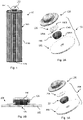
Figure 1 is a longitudinal cross-sectional view of an example battery according to the disclosure, -
Figure 2A is an exploded view showing components of an example safety venting assembly of a battery according to the disclosure, -
Figure 2B is a cross-sectional view showing the example safety venting assembly comprising the components ofFigure 2A in assembled form during normal operation conditions, -
Figure 3A is an exploded view showing components of an example safety venting assembly according to the disclosure, -
Figure 3B is a cross-sectional view showing the example safety venting assembly comprising the components ofFigure 3A in assembled form during normal operation conditions, -
Figure 4A is an exploded view showing components of an example safety venting assembly according to the disclosure, -
Figure 4B is a cross-sectional view showing the example safety venting assembly comprising the components ofFigure 4A in assembled form during normal operation conditions, -
Figure 5A is a schematic diagram depicting a transitional state of the safety venting assembly ofFigure 2B during fail-safe operations, -
Figure 5B is a schematic diagram depicting venting operations of the safety venting assembly ofFigure 2B upon entering into a fail-safe state, -
Figure 6A is an exploded view showing components of an example safety venting assembly according to the disclosure, -
Figure 6B is a cross-sectional view of the example safety venting assembly ofFigure 6A in assembled form during normal operation conditions, -
Figure 7A is an exploded view showing components of an example safety venting assembly according to the disclosure, -
Figure 7B is a cross-sectional view of the example safety venting assembly ofFigure 7A in assembled form during normal operation conditions, -
Figure 8 is a diagram depicting schematically relationship between operational temperature and pressure of an example battery according to the disclosure, -
Figure 9 shows another example battery according to the present disclosure, -
Figure 10A is a cross sectional view of an example venting assembly according to the disclosure, -
Figure 10B is an exploded view showing components of the example venting assembly ofFigure 10A , -
Figure 11A is a perspective view showing an example safety valve sub-assembly, -
Figure 11B is an exploded view showing components of the example safety valve sub-assembly ofFigure 11A , -
Figure 11C is a longitudinal cross-sectional view taken along line A-A' inFigure 11A , -
Figures 12A to 12C are schematic views showing example safety valve subassemblies according to the disclosure, -
Figures 13A to 13E are perspective views of example sealing members, and -
Figures 14A and 14B are perspective views of further example sealing members. - An example
rechargeable battery 10 depicted inFigure 1 comprises an electrode plate group ("EPG") which is contained inside a battery housing. In this example, the battery housing is a steel can 120 which is filled with a battery electrolyte (not shown). Asafety venting assembly 100 is mounted on top of the battery housing and below a top battery terminal. Theelectrode plate group 140 comprises a positive electrode plate group which is connected to apositive battery terminal 122 via a positive current collector, a negative electrode plate group which is connected to anegative battery terminal 124 via a negative current collector, and an insulating separator group providing insulation between the positive and negative electrode plate groups. The battery housing defines a reaction chamber inside which theelectrode plate group 140 is immersed in battery electrolyte and a top cap portion. Thesafety venting assembly 100 is to cooperate with atop cap portion 126 of the battery housing and urges downwardly against a top venting aperture of the steel can 120 to seal the reaction chamber so that the battery electrolyte is retained during storage or normal operations and a fail-safe venting path is provided when pressure inside the reaction chamber exceeds a safety pressure limit or an operational pressure limit. - The example battery is a
cylindrical battery 10 in which a coiledelectrode plate group 140 having a generally cylindrical shape is immersed in an electrolyte contained inside a battery housing having a generally cylindrical shape. The generally cylindrically shaped battery housing comprises a steel can 120 defining a generally cylindrical shaped internal compartment inside which the coiled electrode plate group and the electrolyte are housed, a top cap portion on the cylindrical steel can 120 and asafety assembly 100 between the top cap portion and the cylindrical steel can 120. The positive current collector is connected to a conductive portion of the top cap portion which is in turn connected to the positive battery terminal. The negative current connector is connected to the steel can and the steel can body defines a distributed negative terminal. The safety assembly is to cooperate with the steel can 120 to define a sealed reaction chamber inside which energy conversion processes are to take place during normal battery operations. The top cap portion is to cooperate with the safety assembly to define a buffer region in which the safety assembly is to operate when conditions of the battery is outside safety or operation limits. - The
safety assembly 100 comprises a sealing member which extends transversely across the steel can to partition the battery housing into a first region defining a sealed reaction chamber and a second region above the first region. The second region defines a buffer compartment and a buffer region. - An
example safety assembly 100 depicted inFigure 2A comprises apartitioning member 102, a sealingmember 104 and an urgingmember 106. The partitioning member is in the form of a partitioning plate having a ventingaperture 105 defined at its centre. The partitioningmember 102 has a circular cross-section to follow the circular shape of the steel can 120. The partitioning plate is non-gas permeable and is in a circular shape to correspond to the shape and size of the internal compartment defined by the cylindrical steel can 120 of the battery housing to facilitate sealing of the reaction chamber when the sealing member is in a sealing position during normal battery operation conditions. In some embodiments, a circumferential groove is formed on the interior of the battery housing to hold the partitioning plate in place at an axial level above the bottom of the steel can 120 or at an axial distance above the maximum electrolyte level. The ventingaperture 105 on thepartitioning member 102 is to provide a passageway through which excessive gases built-up in the reaction chamber can be released when the safety mechanism is activated under adverse battery conditions. The size of the venting aperture is determined according to various factors, including the rating of the battery, the size of the reaction chamber, rate of gaseous byproduct generation when outside the normal operation conditions, and/or the required speed of gas release or pressure reduction. - The sealing
member 104 is to seal the venting aperture during normal battery operation conditions when the sealing member is under an axial urging force to urge against the venting aperture. Theexample sealing member 104 shown inFigures 2A and 2B comprises a resilient main body having a firstaxial end portion 104A having a first sealing surface which faces the venting aperture and a secondaxial end portion 104B having a second sealing surface which faces the urgingmember 106, the first and second axial end portions being axially aligned and opposite facing. The firstaxial end portion 104A of the sealingmember 104 is in urging or pressing abutment with thepartitioning member 102 and extends across the entire venting aperture to cover and/ or seal the venting aperture during normal battery operation conditions. The second end portion of the sealing member is in urging or pressing abutment with the urging member and to transmit an axial urging force coming from the urging member to the first end portion. An example resilient main body of an example sealing member is formed of a resilient material such as a resilient rubber including EPDM rubber, synthetic rubber including silicone rubber and natural rubber. - The urging
member 106 is to apply an axial force to urge the sealing member against the venting aperture to seal the venting aperture during normal battery operation conditions. Theexample urging member 106 ofFigure 2B comprises a resilient main body having afirst end portion 106A having an urging surface which faces the sealing member and asecond end portion 106B having a second urging surface which faces thetop cap portion 126, the first and second end portions being axially aligned and opposite facing. Thefirst end portion 106A of the urgingmember 106 is in urging or pressing abutment with the sealing member and thesecond end portion 106B of the urging member is in urging or pressing abutment with the top cap portion. During normal operations, a resilience or compressive urging force stored inside the resilient main body of the urgingmember 106 is to act as an axial urging force against the sealingmember 104 to seal the ventingaperture 105 and to keep the reaction chamber gas tight. - The urging
member 106 has an axial extent or axial thickness and occupies a buffer volume. The buffer volume is defined by a buffer compartment which is in turn defined between the top cap portion and the sealingmember 104. In general, the buffer volume is defined by the axial thickness and transversal extent of the main body, and it has an occupation ratio or a fill ratio of or below 100%. The occupation or fill ratio is the volume ratio between the volume of solid materials inside the buffer volume and the buffer volume. In general, the buffer volume inside the battery housing extends between the axial ends of the urging member and the total volume occupied by or filled with materials of the urging member. The ratio is preferably in the range of 60-95% and more preferably in the range of 75-85%. An example resilient main body of an example urging member is formed of a resilient material such as a resilient thermo-plastic material including polypropylene, nylon, polyethylene and the like. - In the example of
Figure 2A , the urgingmember 106 is moulded of rubber and has a solid base portion on which alternate concentric protrusions and indentations are integrally formed. - The
example safety assembly 200 depicted inFigure 3A comprises apartitioning member 202, a sealingmember 204 and an urgingmember 206. The arrangements of the components are substantially the same as that ofexample safety assembly 100 and the description on theexample safety assembly 100 is incorporated herein by reference with numerals increased by 100 where the numerals relate to the same or functionally equivalent components. In the example ofFigures 3A and3B , the urging member is different to that of Figures 1A and2A and is in the shape of a washer having a hollow central portion - The
example safety assembly 300 depicted inFigure 4A comprises apartitioning member 302, a sealingmember 304 and an urgingmember 306. The arrangements of the components are substantially the same as that ofexample safety assembly 100 and the description on theexample safety assembly 100 is incorporated herein by reference with numerals increased by 200 where the numerals relate to the same or functionally equivalent components. In the example ofFigures 4A and 4B , the urging member is different to that of Figures 1A to 3A and is in the shape of a solid pellet formed of rubber and has a cross-sectional extent smaller than the corresponding cross-sectional area of the battery housing at the axial level at which the urging member is located. - In some embodiments, the top cap portion is in the form of a grille-shaped open structure and the urging member is in the shape of a solid pellet formed of rubber and has a 100% occupation ratio of the battery housing at the axial level at which the urging member is located.
- In some embodiments, the urging member is formed of heat shrinkable material which is to shrink at a predetermined threshold temperature. The heat shrinkable material may a thermoplastic material such as polyolefin, fluoropolymer (such as FEP, PTFE or Kynar), PVC, neoprene, silicone elastomer or Viton.
- In some embodiments, the material forming the urging material has a substantially lower melting point than that of the material forming the sealing member so that when the battery temperature rises to above a predetermined threshold temperature indicating abnormal operation, the urging member will be softened or melted and the sealing member will be pushed upwards towards the top cap portion to open up a venting path by the internal pressure of the reaction chamber. Excessive gas inside the reaction chamber will be released through the venting path to reduce pressure inside the battery housing.
- In some embodiments, the urging member and the sealing member may be formed as a single piece.
- The
example safety assembly 400 depicted inFigure 6A comprises apartitioning member 402, a sealingmember 404 and an urgingmember 406. The arrangements of the components are substantially the same as that ofexample safety assembly 100 and the description on theexample safety assembly 100 is incorporated herein by reference with numerals increased by 300 where the numerals relate to the same or functionally equivalent components. In the example ofFigures 6A and 6B , the urgingmember 406 is moulded into the shape of a circular cap having a base portion and a peripheral wall surrounding a base portion to define a recess or an indentation. The sealingmember 404 has a head portion having a shape and dimension complementary to the recess portion of the urging member. The urging member and the sealing member are formed as a single piece by over-moulding with the head portion of the sealing member received inside the recess of the urging portion in a closely fitted manner by over-moulding. In some embodiments, the recess extends through the base portion to define a through aperture extending axially through the urging member. - The
example safety assembly 500 depicted inFigure 7A comprises apartitioning member 502, a sealingmember 504 and an urgingmember 506. The arrangements of the components are substantially the same as that ofexample safety assembly 400 and the description on theexample safety assembly 400 is incorporated herein by reference with numerals increased by 100 where the numerals relate to the same or functionally equivalent components. In the example ofFigures 7A and 7B , the urgingmember 506 is moulded into the shape of a circular cap having a base portion and a peripheral wall surrounding a base portion to define a recess or an indentation. The sealingmember 504 has a head portion having a shape and dimension complementary to the recess portion of the urging member. The urging member and the sealing member are formed as a single piece by over-moulding with the head portion of the sealing member received inside the recess of the urging portion in a closely fitted manner by over-moulding. A plurality of concentric ribs is formed on an axial end of the base portion distal from the sealing member. The concentric ribs projecting axially from the base portion in an axial direction away from the sealing member to define a plurality of concentric grooves. - An example safety or venting
assembly 600 depicted inFigure 10A is part of a battery. The battery comprises an electrode plate group which is housed inside a battery housing. The electrode plate group is immersed inside a battery electrolyte which is contained inside an electrolyte container defined by the battery housing. A reaction chamber which is cooperatively formed by the electrode plate group, the battery electrolyte and the electrolyte container is sealed by the ventingassembly 600 in cooperation with a top end cap portion of the battery housing. - The example safety or venting
assembly 600 comprises a partitioning member orplate 602, a sealingmember 604 and an urgingmember 606, as depicted inFigure 10B . The arrangements of the components are substantially the same as that ofexample safety assembly 400/500 and the description on theexample safety assembly 400/500 is incorporated herein by reference with numerals increased by 200/100, wherein like numerals represent like components. - In the example safety venting assembly of
Figures 10A and 10B , the urgingmember 606 and the sealingmember 604 cooperate to form a valve sub-assembly. The urgingmember 606 is formed of a heat melt-able or heat deformable material which is rigid during normal working temperature of the battery and which is to melt or soften to deform when a threshold venting temperature is reached. The urgingmember 606 includes an upper portion which extends transversely in a radial direction to form a ceiling portion and a skirt portion which is formed on the outer periphery of the ceiling portion and which projects axially downwards and away from the ceiling portion. The skirt portion includes indentations which are distributed along its perimeter to define a plurality of retention teeth. The retention teeth are distributed along periphery of urging member and project axially downwards to define a retention compartment inside which the sealingmember 604 is securely seated or tightly received. - In some embodiments, the urging member includes an indentation or a plurality of indentations, for example, on the upper portion so that materials forming the urging member can flow into the indentation to reduce axial thickness of the urging member to provide room for operatively movement of the sealing member when the venting temperature has reached, For example, an arcuate groove or a plurality of arcuate grooves is formed on the upper portion to provide room from deformation flow.
- In some embodiments, the urging
member 606 is moulded of hard thermal plastics, for example, polyethylene. Where the urgingmember 606 is moulded of hard thermal plastics, resilience of the retention teeth will cooperate to exert a radial compression force to keep the sealingmember 604 inside the retention compartment or sealingmember 604 receptacle defined by the plurality of retention teeth. In such embodiments, the urgingmember 606 forms a clasp to firmly hold the sealingmember 604 inside the retention compartment. - The urging
member 606 is made of a material having a substantially lower melting or softening temperature so that it will melt or softens while the sealingmember 604 is substantially un-deformed so that the sealingmember 604 would not interfere with or fill the venting aperture on the partitioning member orplate 602 when the venting temperature is reached. For example, where the venting temperature is set at 130°C as depicted inFigure 8 , the urgingmember 606 will deform when the temperature of the battery has reached 130 °C while the sealing member will remain un-deformed or substantially un-deformed. When temperature trigger deformation occurs at the urging member, pressure inside the reaction chamber will push the sealing member to move away from the venting aperture to provide a venting path to relieve internal pressure. - In some embodiments, the urging
member 606 is moulded into the shape of a circular cap having a base portion and a peripheral wall surrounding a base portion to define a recess or an indentation. In some embodiments, the peripheral wall might comprise a plurality notches being evenly or non-evenly spaced apart from each other on the periphery of the circular cap or about the central axis of the circular cap. The sealingmember 604 has a head portion having a shape and dimension complementary to the recess portion of the urging member. In the present embodiment, the recess extends through the base portion to define a through aperture extending axially through the urging member. The urging member and the sealing member might be formed as a single piece by over-moulding with the head portion of the sealing member received inside the recess of the urging portion in a closely fitted manner by over-moulding. A plurality of concentric ribs is formed on an axial end of the base portion distal from the sealing member. The concentric ribs projecting axially from the base portion in an axial direction away from the sealing member to define a plurality of concentric grooves. - Similarly, a plurality of concentric ribs and/or a couple of protrusions might be formed on an axial end of the head portion of the sealing member proximate to the urging member. The concentric ribs and/or the couple of protrusions projecting axially from the head portion in an axial direction towards the urging member to complement or engage with same or functionally equivalent contact plane or portions such as recesses arranged at the urging member.
- In some embodiments, the sealing member might be a profiled member rather than a cylindrical member. For example, at least a portion (e.g. an upper portion, a lower portion, and/or an intermediate portion) of the sealing member might be of any regular shapes, such as triangular, square, rectangular, polygonal, star-like, cross-like, or the like, as shown in
Figures 13A-13E . In some embodiments, the sealing member might be a profiled member (a member in various forms and dimensions) having a l-shaped or T-shaped cross-sectional profile, as shown inFigures 14A-14B . - In some embodiments, the urging member and the sealing member might be simply stacked together, or they could be welded, glued or bonded so as to form a sandwich like structure in case that either of both of the urging member and the sealing member being in form of a multi-layered member made of same or various materials, as shown in
Figure 12A . The dash lines are used to indicate that the urging member and the sealing member might comprise multiple layers of same or different materials. - In some embodiments, the urging member and the sealing member might comprise complementary portions for engagement and might be joined together by interlocking joint, dowel joint, mechanical joint such as bolted joint, screw joint, welded joint, etc., or any other means well known in the art, as shown in
Figures 11A-11C . - In some embodiments, the urging member and the sealing member might be of same size or dimension. Alternatively, the sealing member might be substantially larger/smaller than the urging member, or vice versa, as shown in
Figures 12B-12C . In other words, the sealing member might be at least partially enclosed or wrapped by the urging member as shown in foregoing embodiments. Alternatively, the urging member might be in turn at least partially enclosed or wrapped by the sealing member depending on the actual design and requirements of a specific application. - The sealing member may have different shapes and dimensions, as depicted in
Figures 13A to 13E . In general, regardless of the shape and dimension, each sealing member has a central portion having a foot print sufficient to cover the venting aperture during storage or normal operations. - While the sealing members depicted in
Figures 13A to 13E are substantially prismatic, it should be appreciated that the sealing members need not be prismatic and may have nonuniform cross section along its axial or longitudinal direction. - As depicted in the example of
Figures 14A and 14B , the sealing member may have a T- or l-shaped profiled along its length. - The melting or softening temperature of the urging member and the sealing member may be selected according to operational environmental requirements. Examples of temperature ranges are set out in Table 1 below:
Table 1 Urging Member Melting Temperature (Tg) Sealing Member Melting Temperature (Tg) Low temperature series 50-100, or 50-150 ° C 300 or 301-500 °C Normal temperature series 100-200 ° C 300 or 301-500 °C High temperature series 150-250 ° C 300 or 301-500 °C Ultra high temperature series 200-300 ° C 300 or 301-500 °C - In operation, energy conversion taking place in the reaction chamber will generate heat and gases. When the heat generated by the reaction chamber exceeds a threshold temperature corresponding to a predetermined limit, the resilient urging
member Figure 5A . When this happens, the axial extent occupied by the urging member will be reduced and the internal pressure inside the reaction chamber will push the deformed urging member towards thetop cap portion 226. As a result a venting path to relieve internal pressure is built up and pressure inside the reaction chamber will be reduced without interrupting operation of the battery. - As depicted in
Figure 8 , the internal pressure of thebattery 100 having a heat triggered venting assembly is well reduced before the temperature rises to an unacceptable level, compared to conventional pressure triggered venting arrangements. - An example
prismatic battery 20 depicted inFigure 9 comprises an electrode plate group ("EPG") which is contained inside a battery housing and filled with an electrolyte (not shown) and a safety venting assembly. The electrode plate group comprises a positive electrode plate group which is connected to a positive battery terminal via a positive current collector, a negative electrode plate group which is connected to a negative battery terminal via a negative current collector, and an insulating separator group providing insulation between the positive and negative electrode plate groups. Thebattery 20 have similar structural features as that ofbattery 10 except that the battery housing is prismatic, and both positive andnegative battery terminals safety assembly - In some embodiments, the example
cylindrical battery 10 is a NiMH (Nickel Metal Hydride) battery having a positive electrode formed of nickel hydroxide, a negative electrode formed of hydrogen absorbing alloy, a separator and a strong alkaline electrolyte such as KOH, NaOH and LiOH. The separator may for example be formed of non-woven polypropylene (PP). - In some embodiments, the
battery - While the disclosure is with reference to the above examples, it should be appreciated that the examples are for illustration only and should not be used to limit the scope of disclosure.
Table of Numerals: 10, 20 Battery 100,200,300, 400, 500, 600 Venting / safety assembly 120 Battery can 102,202,302, 402, 502, 602 Partitioning member/ plate 122 Positive battery terminal 104,204,304, 404, 504, 604 Sealing member 124 negative battery terminal 106,206,306, 406, 506, 606 Urging member 126 Battery top cap end portion
Claims (15)
- A battery (10) comprising a reaction chamber and a safety vent assembly (100; 200; 300; 400; 500; 600), the safety vent assembly (100; 200; 300; 400; 500; 600) comprising a sealing member (104; 204; 304; 404; 504; 604) and an urging member (106; 206; 306; 406; 506; 606) to urge the sealing member (104; 204; 304; 404; 504; 604) against a venting aperture (105) on the battery reaction chamber to seal the battery reaction chamber under normal operation conditions,
wherein:the urging member (106; 206; 306; 406; 506; 606) softens and/or melts on reaching a threshold venting temperature whereby the urging member (106; 206; 306; 406; 506; 606) deforms such that an axial thickness of the urging member (106; 206; 306; 406; 506; 606) is reduced so that the sealing member (104; 204; 304; 404; 504; 604) is urged by pressure inside the reaction chamber to form or open up a venting path through which gases from the reaction chamber can pass or escape out of the reaction chamber though the venting aperture (105) to reduce pressure inside the reaction chamber;the urging member (106; 206; 306; 406; 506; 606) is made of a resilient thermoplastic material; andthe sealing member (104; 204; 304; 404; 504; 604) is made of a resilient material; andwherein:the urging member (106; 206; 306; 406; 506; 606) comprises at least one indentation so that melted materials forming the urging member (106; 206; 306; 406; 506; 606) flow into the at least one indentation to reduce the axial thickness of the urging member (106; 206; 306; 406; 506; 606); and/orthe sealing member (104; 204; 304; 404; 504; 604) has an outer periphery larger than that of the urging member (106; 206; 306; 406; 506; 606) or vice-versa. - A battery (10) according to Claim 1, wherein the urging member (106; 206; 306; 406; 506; 606) is resilient, and the urging member (106; 206; 306; 406; 506; 606) is under resilient compression to apply an axial urging force on the sealing member (104; 204; 304; 404; 504; 604) to seal the venting aperture (105) under normal operation conditions.
- A battery (10) according to Claims 1 or 2, wherein the urging member (106; 206; 306; 406; 506; 606) is formed of a resilient material and has a softening or melting temperature below the softening or melting temperature of said sealing member (104; 204; 304; 404; 504; 604).
- A battery (10) according to any preceding Claim, wherein the sealing member (104; 204; 304; 404; 504; 604) is made of rubber.
- A battery (10) according to Claim 1, wherein the urging member (106; 206; 306; 406; 506; 606) has a main body and local protrusions on the main body, the local protrusions make localised thermal contact with a battery housing.
- A battery (10) according to any one of Claims 1-4, wherein the urging member (106; 206; 306; 406; 506; 606) has a washer, donut or grille shaped main body defining at least a hollow portion.
- A battery (10) according to any preceding Claim, wherein the urging member (106; 206; 306; 406; 506; 606) has a melting temperature between 50°C and 300°C, including 80°C to 280°C, and further including 100°C -200°C.
- A battery (10) according to any preceding Claim, wherein the sealing member (104; 204; 304; 404; 504; 604) has a melting temperature of between 300°C or 301°C and 500 °C, including 310°C to 490°C, further including 350°C to 450°C.
- A battery (10) according to any preceding Claim, wherein the sealing member (104; 204; 304; 404; 504; 604) and the urging member (106; 206; 306; 406; 506; 606) are formed as a single piece.
- A battery (10) according to any preceding Claim, wherein the sealing member (104; 204; 304; 404; 504; 604) and the urging member (106; 206; 306; 406; 506; 606) comprise complementary portions for coupling or engaging with each other by interlocking joint, dowel joint, and/or mechanical joint.
- A battery (10) according to any preceding Claim, wherein the sealing member (104; 204; 304; 404; 504; 604) is in form of any of triangular, square, rectangular, polygonal, star-like, cross-like shapes.
- A battery (10) according to any preceding Claim, wherein the sealing member (104; 204; 304; 404; 504; 604) is a profiled member having a l-shaped or T-shaped cross-sectional profile.
- A battery (10) according to any preceding Claim, wherein the urging member (106; 206; 306; 406; 506; 606) and/or the sealing member (104; 204; 304; 404; 504; 604) being in form of a multi-layered member made of same or various materials and multiple layers of the multi-layered member are stacked, welded, and/or glued together.
- A battery (10) according to Claim 1, wherein the urging member (106; 206; 306; 406; 506; 606) has an occupation ratio or a fill ratio, the occupation ratio or fill ratio is a volume ratio between a volume occupied by the materials forming the urging member (106; 206; 306; 406; 506; 606) and an external volume defined by an external or outer dimension of the urging member (106; 206; 306; 406; 506; 606), the occupation ratio or fill ratio is preferably in a range of 60%-95% and more preferably in a range of 75%-85%, and the external volume defines a buffer volume inside a battery housing which extends between axial ends of the urging member (106; 206; 306; 406; 506; 606).
- A battery (10) according to Claim 1, wherein the sealing member (104; 204; 304; 404; 504; 604) is at least partially enclosed or wrapped by the urging member (106; 206; 306; 406; 506; 606).
Applications Claiming Priority (3)
| Application Number | Priority Date | Filing Date | Title |
|---|---|---|---|
| HK14110414 | 2014-10-17 | ||
| HK15106963 | 2015-07-21 | ||
| PCT/IB2015/058024 WO2016059618A1 (en) | 2014-10-17 | 2015-10-19 | Batteries |
Publications (3)
| Publication Number | Publication Date |
|---|---|
| EP3207578A1 EP3207578A1 (en) | 2017-08-23 |
| EP3207578A4 EP3207578A4 (en) | 2018-03-14 |
| EP3207578B1 true EP3207578B1 (en) | 2022-12-14 |
Family
ID=55746223
Family Applications (1)
| Application Number | Title | Priority Date | Filing Date |
|---|---|---|---|
| EP15851084.2A Active EP3207578B1 (en) | 2014-10-17 | 2015-10-19 | Batteries |
Country Status (4)
| Country | Link |
|---|---|
| US (1) | US10734625B2 (en) |
| EP (1) | EP3207578B1 (en) |
| CN (2) | CN112909419A (en) |
| WO (1) | WO2016059618A1 (en) |
Families Citing this family (10)
| Publication number | Priority date | Publication date | Assignee | Title |
|---|---|---|---|---|
| DE102015214256A1 (en) * | 2015-07-28 | 2017-02-02 | Bimed Teknik A.S. | Pressure-balancing device |
| JP6876426B2 (en) | 2016-12-21 | 2021-05-26 | Fdk株式会社 | Alkaline secondary battery |
| KR102397764B1 (en) * | 2017-12-13 | 2022-05-13 | 삼성에스디아이 주식회사 | Cylindrical Lithium Ion Secondary Battery |
| CN110429214B (en) * | 2019-08-07 | 2021-12-07 | 宁德时代新能源科技股份有限公司 | Cap assembly for secondary battery and secondary battery |
| CN110391367B (en) * | 2019-08-08 | 2022-01-28 | 宁德时代新能源科技股份有限公司 | Cap assembly for secondary battery and secondary battery |
| CN209981287U (en) * | 2019-08-15 | 2020-01-21 | 宁德时代新能源科技股份有限公司 | Cap assembly for secondary battery and secondary battery |
| WO2022067809A1 (en) * | 2020-09-30 | 2022-04-07 | 宁德时代新能源科技股份有限公司 | Battery, device, and preparation method and preparation device for battery |
| CN112098852B (en) * | 2020-11-11 | 2021-02-09 | 国网江苏省电力有限公司经济技术研究院 | Method and device for analyzing gas production rate of lithium battery under thermal runaway |
| CN112952243B (en) | 2020-11-16 | 2023-03-28 | 江苏时代新能源科技有限公司 | End cover assembly, battery monomer, exhaust method, battery and electric device |
| EP4152479A4 (en) | 2021-07-30 | 2023-09-13 | Contemporary Amperex Technology Co., Limited | Battery group, battery pack and electric apparatus |
Family Cites Families (17)
| Publication number | Priority date | Publication date | Assignee | Title |
|---|---|---|---|---|
| US3939011A (en) | 1973-01-05 | 1976-02-17 | P. R. Mallory & Co. Inc. | Lithium cell with internal automatic safety controls |
| JPS59224049A (en) * | 1983-04-11 | 1984-12-15 | ジ−テイ−イ−・コミユニケイシヨンズ・プロダクツ・コ−ポレイシヨン | Electrochemical battery |
| JPS62147652A (en) * | 1985-12-23 | 1987-07-01 | Matsushita Electric Ind Co Ltd | Sealed lead-acid battery |
| CA2000873C (en) | 1988-10-21 | 1999-12-14 | Shigeru Oishi | Cell having current cutoff valve |
| JP3387118B2 (en) | 1992-06-12 | 2003-03-17 | ソニー株式会社 | Sealed battery |
| JPH06325742A (en) * | 1993-05-14 | 1994-11-25 | Toshiba Battery Co Ltd | Safety valve device of sealed battery |
| US5750277A (en) | 1996-04-10 | 1998-05-12 | Texas Instruments Incorporated | Current interrupter for electrochemical cells |
| CA2381376C (en) | 2002-04-10 | 2008-12-02 | E-One Moli Energy (Canada) Limited | Header for rechargeable lithium batteries |
| US20040043286A1 (en) * | 2002-08-28 | 2004-03-04 | Janmey Robert M. | Seal for an electrochemical cell |
| JP4701636B2 (en) * | 2004-06-03 | 2011-06-15 | 株式会社Gsユアサ | Sealed storage battery exhaust valve, sealed storage battery using the same, sealed nickel metal hydride storage battery |
| JP2006092864A (en) * | 2004-09-22 | 2006-04-06 | Sanyo Electric Co Ltd | Safety valve device and sealed battery |
| CN2899125Y (en) * | 2005-12-28 | 2007-05-09 | 比亚迪股份有限公司 | Battery positive cap and battery therewith |
| JP4358245B2 (en) * | 2007-03-09 | 2009-11-04 | レノボ・シンガポール・プライベート・リミテッド | Battery pack and portable electronic device |
| CN201498537U (en) * | 2008-04-11 | 2010-06-02 | 于湘勇 | Cover plate of lithium battery of plastics and plastic film with function of explosion prevention |
| CN101867067B (en) * | 2009-04-17 | 2012-01-25 | 深圳市格瑞普电池有限公司 | Anti-explosion nickel battery and anti-explosion ball and preparation method thereof |
| CN102290547B (en) * | 2011-07-28 | 2014-01-08 | 深圳市豪鹏科技有限公司 | Battery anode cap and preparation method thereof and secondary battery using battery anode cap |
| CN202231080U (en) * | 2011-09-30 | 2012-05-23 | 李震祺 | Pressure relief device |
-
2015
- 2015-10-19 WO PCT/IB2015/058024 patent/WO2016059618A1/en active Application Filing
- 2015-10-19 CN CN202110001434.3A patent/CN112909419A/en active Pending
- 2015-10-19 US US15/744,850 patent/US10734625B2/en active Active
- 2015-10-19 CN CN201580069179.9A patent/CN107112473B/en active Active
- 2015-10-19 EP EP15851084.2A patent/EP3207578B1/en active Active
Also Published As
| Publication number | Publication date |
|---|---|
| EP3207578A4 (en) | 2018-03-14 |
| WO2016059618A1 (en) | 2016-04-21 |
| US10734625B2 (en) | 2020-08-04 |
| CN107112473A (en) | 2017-08-29 |
| CN112909419A (en) | 2021-06-04 |
| EP3207578A1 (en) | 2017-08-23 |
| CN107112473B (en) | 2021-02-26 |
| US20180159101A1 (en) | 2018-06-07 |
Similar Documents
| Publication | Publication Date | Title |
|---|---|---|
| EP3207578B1 (en) | Batteries | |
| US20200411824A1 (en) | Battery including safety vent assembly | |
| US7572544B2 (en) | Sealed rechargeable battery | |
| JP5771155B2 (en) | Closure assembly for electrochemical cells | |
| KR101340659B1 (en) | Closure vent seal and assembly | |
| JP6490053B2 (en) | Cylindrical sealed battery and battery pack | |
| KR101131258B1 (en) | Housing for a sealed electrochemical battery cell | |
| EP0973213B1 (en) | Explosion-proof nonaqueous electrolyte secondary cell and rupture pressure setting method therefor | |
| US6620544B1 (en) | Sealed battery | |
| CN110429214B (en) | Cap assembly for secondary battery and secondary battery | |
| US20100291422A1 (en) | Cap assembly for use in lithium ion batteries | |
| KR102072762B1 (en) | Can Type Secondary Battery and Secondary Battery Module including the same | |
| KR20060022556A (en) | Lithium ion secondary battery having shape-memory alloy safety vent | |
| KR100560494B1 (en) | cap assembly and secondary battery utilizing the same | |
| JP4806936B2 (en) | Sealed battery | |
| EP3185334B1 (en) | Secondary battery | |
| US20050026033A1 (en) | Hermetically sealed battery | |
| JPH08153536A (en) | Sealed nonaqueous secondary battery | |
| JP2023528937A (en) | Secondary batteries and devices containing them | |
| JP2006066269A (en) | Sealed-type storage battery | |
| KR100696787B1 (en) | Cap Assembly and Lithium Ion Secondary Battery with the same | |
| KR101279408B1 (en) | Method for manufacturing secondary battery | |
| JP2005190837A (en) | Sealed storage battery | |
| CN103155211B (en) | Battery with over-pressure safety device | |
| JP3027932B2 (en) | Sealed battery |
Legal Events
| Date | Code | Title | Description |
|---|---|---|---|
| STAA | Information on the status of an ep patent application or granted ep patent |
Free format text: STATUS: THE INTERNATIONAL PUBLICATION HAS BEEN MADE |
|
| PUAI | Public reference made under article 153(3) epc to a published international application that has entered the european phase |
Free format text: ORIGINAL CODE: 0009012 |
|
| STAA | Information on the status of an ep patent application or granted ep patent |
Free format text: STATUS: REQUEST FOR EXAMINATION WAS MADE |
|
| 17P | Request for examination filed |
Effective date: 20170510 |
|
| AK | Designated contracting states |
Kind code of ref document: A1 Designated state(s): AL AT BE BG CH CY CZ DE DK EE ES FI FR GB GR HR HU IE IS IT LI LT LU LV MC MK MT NL NO PL PT RO RS SE SI SK SM TR |
|
| AX | Request for extension of the european patent |
Extension state: BA ME |
|
| RIN1 | Information on inventor provided before grant (corrected) |
Inventor name: SHAM, SEK YIN Inventor name: TSANG, HING PO |
|
| RAP1 | Party data changed (applicant data changed or rights of an application transferred) |
Owner name: GP BATTERIES INTERNATIONAL LIMITED |
|
| DAV | Request for validation of the european patent (deleted) | ||
| DAX | Request for extension of the european patent (deleted) | ||
| RAP1 | Party data changed (applicant data changed or rights of an application transferred) |
Owner name: GP BATTERIES INTERNATIONAL LIMITED |
|
| A4 | Supplementary search report drawn up and despatched |
Effective date: 20180213 |
|
| RIC1 | Information provided on ipc code assigned before grant |
Ipc: H01M 2/12 20060101AFI20180205BHEP |
|
| STAA | Information on the status of an ep patent application or granted ep patent |
Free format text: STATUS: EXAMINATION IS IN PROGRESS |
|
| 17Q | First examination report despatched |
Effective date: 20190205 |
|
| STAA | Information on the status of an ep patent application or granted ep patent |
Free format text: STATUS: EXAMINATION IS IN PROGRESS |
|
| REG | Reference to a national code |
Ref country code: DE Ref legal event code: R079 Ref document number: 602015081970 Country of ref document: DE Free format text: PREVIOUS MAIN CLASS: H01M0002120000 Ipc: H01M0050375000 |
|
| GRAP | Despatch of communication of intention to grant a patent |
Free format text: ORIGINAL CODE: EPIDOSNIGR1 |
|
| STAA | Information on the status of an ep patent application or granted ep patent |
Free format text: STATUS: GRANT OF PATENT IS INTENDED |
|
| RIC1 | Information provided on ipc code assigned before grant |
Ipc: H01M 50/375 20210101AFI20220620BHEP |
|
| INTG | Intention to grant announced |
Effective date: 20220705 |
|
| GRAS | Grant fee paid |
Free format text: ORIGINAL CODE: EPIDOSNIGR3 |
|
| GRAA | (expected) grant |
Free format text: ORIGINAL CODE: 0009210 |
|
| STAA | Information on the status of an ep patent application or granted ep patent |
Free format text: STATUS: THE PATENT HAS BEEN GRANTED |
|
| AK | Designated contracting states |
Kind code of ref document: B1 Designated state(s): AL AT BE BG CH CY CZ DE DK EE ES FI FR GB GR HR HU IE IS IT LI LT LU LV MC MK MT NL NO PL PT RO RS SE SI SK SM TR |
|
| REG | Reference to a national code |
Ref country code: GB Ref legal event code: FG4D |
|
| REG | Reference to a national code |
Ref country code: CH Ref legal event code: EP |
|
| REG | Reference to a national code |
Ref country code: DE Ref legal event code: R096 Ref document number: 602015081970 Country of ref document: DE |
|
| REG | Reference to a national code |
Ref country code: IE Ref legal event code: FG4D |
|
| REG | Reference to a national code |
Ref country code: AT Ref legal event code: REF Ref document number: 1538219 Country of ref document: AT Kind code of ref document: T Effective date: 20230115 |
|
| REG | Reference to a national code |
Ref country code: LT Ref legal event code: MG9D |
|
| REG | Reference to a national code |
Ref country code: NL Ref legal event code: MP Effective date: 20221214 |
|
| PG25 | Lapsed in a contracting state [announced via postgrant information from national office to epo] |
Ref country code: SE Free format text: LAPSE BECAUSE OF FAILURE TO SUBMIT A TRANSLATION OF THE DESCRIPTION OR TO PAY THE FEE WITHIN THE PRESCRIBED TIME-LIMIT Effective date: 20221214 Ref country code: NO Free format text: LAPSE BECAUSE OF FAILURE TO SUBMIT A TRANSLATION OF THE DESCRIPTION OR TO PAY THE FEE WITHIN THE PRESCRIBED TIME-LIMIT Effective date: 20230314 Ref country code: LT Free format text: LAPSE BECAUSE OF FAILURE TO SUBMIT A TRANSLATION OF THE DESCRIPTION OR TO PAY THE FEE WITHIN THE PRESCRIBED TIME-LIMIT Effective date: 20221214 Ref country code: FI Free format text: LAPSE BECAUSE OF FAILURE TO SUBMIT A TRANSLATION OF THE DESCRIPTION OR TO PAY THE FEE WITHIN THE PRESCRIBED TIME-LIMIT Effective date: 20221214 |
|
| REG | Reference to a national code |
Ref country code: AT Ref legal event code: MK05 Ref document number: 1538219 Country of ref document: AT Kind code of ref document: T Effective date: 20221214 |
|
| PG25 | Lapsed in a contracting state [announced via postgrant information from national office to epo] |
Ref country code: RS Free format text: LAPSE BECAUSE OF FAILURE TO SUBMIT A TRANSLATION OF THE DESCRIPTION OR TO PAY THE FEE WITHIN THE PRESCRIBED TIME-LIMIT Effective date: 20221214 Ref country code: LV Free format text: LAPSE BECAUSE OF FAILURE TO SUBMIT A TRANSLATION OF THE DESCRIPTION OR TO PAY THE FEE WITHIN THE PRESCRIBED TIME-LIMIT Effective date: 20221214 Ref country code: HR Free format text: LAPSE BECAUSE OF FAILURE TO SUBMIT A TRANSLATION OF THE DESCRIPTION OR TO PAY THE FEE WITHIN THE PRESCRIBED TIME-LIMIT Effective date: 20221214 Ref country code: GR Free format text: LAPSE BECAUSE OF FAILURE TO SUBMIT A TRANSLATION OF THE DESCRIPTION OR TO PAY THE FEE WITHIN THE PRESCRIBED TIME-LIMIT Effective date: 20230315 |
|
| RAP2 | Party data changed (patent owner data changed or rights of a patent transferred) |
Owner name: GP TECHNOLOGY & INNOVATION LIMITED |
|
| PG25 | Lapsed in a contracting state [announced via postgrant information from national office to epo] |
Ref country code: NL Free format text: LAPSE BECAUSE OF FAILURE TO SUBMIT A TRANSLATION OF THE DESCRIPTION OR TO PAY THE FEE WITHIN THE PRESCRIBED TIME-LIMIT Effective date: 20221214 |
|
| PG25 | Lapsed in a contracting state [announced via postgrant information from national office to epo] |
Ref country code: SM Free format text: LAPSE BECAUSE OF FAILURE TO SUBMIT A TRANSLATION OF THE DESCRIPTION OR TO PAY THE FEE WITHIN THE PRESCRIBED TIME-LIMIT Effective date: 20221214 Ref country code: RO Free format text: LAPSE BECAUSE OF FAILURE TO SUBMIT A TRANSLATION OF THE DESCRIPTION OR TO PAY THE FEE WITHIN THE PRESCRIBED TIME-LIMIT Effective date: 20221214 Ref country code: PT Free format text: LAPSE BECAUSE OF FAILURE TO SUBMIT A TRANSLATION OF THE DESCRIPTION OR TO PAY THE FEE WITHIN THE PRESCRIBED TIME-LIMIT Effective date: 20230414 Ref country code: ES Free format text: LAPSE BECAUSE OF FAILURE TO SUBMIT A TRANSLATION OF THE DESCRIPTION OR TO PAY THE FEE WITHIN THE PRESCRIBED TIME-LIMIT Effective date: 20221214 Ref country code: EE Free format text: LAPSE BECAUSE OF FAILURE TO SUBMIT A TRANSLATION OF THE DESCRIPTION OR TO PAY THE FEE WITHIN THE PRESCRIBED TIME-LIMIT Effective date: 20221214 Ref country code: CZ Free format text: LAPSE BECAUSE OF FAILURE TO SUBMIT A TRANSLATION OF THE DESCRIPTION OR TO PAY THE FEE WITHIN THE PRESCRIBED TIME-LIMIT Effective date: 20221214 Ref country code: AT Free format text: LAPSE BECAUSE OF FAILURE TO SUBMIT A TRANSLATION OF THE DESCRIPTION OR TO PAY THE FEE WITHIN THE PRESCRIBED TIME-LIMIT Effective date: 20221214 |
|
| P01 | Opt-out of the competence of the unified patent court (upc) registered |
Effective date: 20230718 |
|
| PG25 | Lapsed in a contracting state [announced via postgrant information from national office to epo] |
Ref country code: SK Free format text: LAPSE BECAUSE OF FAILURE TO SUBMIT A TRANSLATION OF THE DESCRIPTION OR TO PAY THE FEE WITHIN THE PRESCRIBED TIME-LIMIT Effective date: 20221214 Ref country code: PL Free format text: LAPSE BECAUSE OF FAILURE TO SUBMIT A TRANSLATION OF THE DESCRIPTION OR TO PAY THE FEE WITHIN THE PRESCRIBED TIME-LIMIT Effective date: 20221214 Ref country code: IS Free format text: LAPSE BECAUSE OF FAILURE TO SUBMIT A TRANSLATION OF THE DESCRIPTION OR TO PAY THE FEE WITHIN THE PRESCRIBED TIME-LIMIT Effective date: 20230414 Ref country code: AL Free format text: LAPSE BECAUSE OF FAILURE TO SUBMIT A TRANSLATION OF THE DESCRIPTION OR TO PAY THE FEE WITHIN THE PRESCRIBED TIME-LIMIT Effective date: 20221214 |
|
| REG | Reference to a national code |
Ref country code: DE Ref legal event code: R097 Ref document number: 602015081970 Country of ref document: DE |
|
| PLBE | No opposition filed within time limit |
Free format text: ORIGINAL CODE: 0009261 |
|
| STAA | Information on the status of an ep patent application or granted ep patent |
Free format text: STATUS: NO OPPOSITION FILED WITHIN TIME LIMIT |
|
| PG25 | Lapsed in a contracting state [announced via postgrant information from national office to epo] |
Ref country code: DK Free format text: LAPSE BECAUSE OF FAILURE TO SUBMIT A TRANSLATION OF THE DESCRIPTION OR TO PAY THE FEE WITHIN THE PRESCRIBED TIME-LIMIT Effective date: 20221214 |
|
| 26N | No opposition filed |
Effective date: 20230915 |
|
| PG25 | Lapsed in a contracting state [announced via postgrant information from national office to epo] |
Ref country code: SI Free format text: LAPSE BECAUSE OF FAILURE TO SUBMIT A TRANSLATION OF THE DESCRIPTION OR TO PAY THE FEE WITHIN THE PRESCRIBED TIME-LIMIT Effective date: 20221214 |
|
| PGFP | Annual fee paid to national office [announced via postgrant information from national office to epo] |
Ref country code: GB Payment date: 20231017 Year of fee payment: 9 |
|
| PGFP | Annual fee paid to national office [announced via postgrant information from national office to epo] |
Ref country code: FR Payment date: 20231024 Year of fee payment: 9 Ref country code: DE Payment date: 20231031 Year of fee payment: 9 |