EP3207302B1 - Holding device for a test sheet - Google Patents
Holding device for a test sheet Download PDFInfo
- Publication number
- EP3207302B1 EP3207302B1 EP15781345.2A EP15781345A EP3207302B1 EP 3207302 B1 EP3207302 B1 EP 3207302B1 EP 15781345 A EP15781345 A EP 15781345A EP 3207302 B1 EP3207302 B1 EP 3207302B1
- Authority
- EP
- European Patent Office
- Prior art keywords
- pushbutton
- holding device
- arrangement
- handle
- user
- Prior art date
- Legal status (The legal status is an assumption and is not a legal conclusion. Google has not performed a legal analysis and makes no representation as to the accuracy of the status listed.)
- Active
Links
- 238000012360 testing method Methods 0.000 title claims description 32
- 238000005555 metalworking Methods 0.000 claims description 19
- 239000012636 effector Substances 0.000 claims description 6
- 238000013461 design Methods 0.000 claims description 4
- 230000003213 activating effect Effects 0.000 claims 1
- 239000000523 sample Substances 0.000 description 17
- 210000003811 finger Anatomy 0.000 description 16
- 210000004247 hand Anatomy 0.000 description 6
- 239000000969 carrier Substances 0.000 description 5
- 230000001419 dependent effect Effects 0.000 description 4
- 230000005540 biological transmission Effects 0.000 description 2
- 210000000245 forearm Anatomy 0.000 description 2
- 238000004519 manufacturing process Methods 0.000 description 2
- 239000000463 material Substances 0.000 description 2
- 238000000034 method Methods 0.000 description 2
- 238000012545 processing Methods 0.000 description 2
- 244000261422 Lysimachia clethroides Species 0.000 description 1
- 229910052782 aluminium Inorganic materials 0.000 description 1
- XAGFODPZIPBFFR-UHFFFAOYSA-N aluminium Chemical compound [Al] XAGFODPZIPBFFR-UHFFFAOYSA-N 0.000 description 1
- 238000013459 approach Methods 0.000 description 1
- 230000000712 assembly Effects 0.000 description 1
- 238000000429 assembly Methods 0.000 description 1
- 238000006243 chemical reaction Methods 0.000 description 1
- 238000010276 construction Methods 0.000 description 1
- 238000003754 machining Methods 0.000 description 1
- 238000003825 pressing Methods 0.000 description 1
- 230000002035 prolonged effect Effects 0.000 description 1
- 230000035939 shock Effects 0.000 description 1
- 210000003813 thumb Anatomy 0.000 description 1
- 230000001960 triggered effect Effects 0.000 description 1
Images


Classifications
-
- B—PERFORMING OPERATIONS; TRANSPORTING
- B21—MECHANICAL METAL-WORKING WITHOUT ESSENTIALLY REMOVING MATERIAL; PUNCHING METAL
- B21J—FORGING; HAMMERING; PRESSING METAL; RIVETING; FORGE FURNACES
- B21J15/00—Riveting
- B21J15/38—Accessories for use in connection with riveting, e.g. pliers for upsetting; Hand tools for riveting
- B21J15/42—Special clamping devices for workpieces to be riveted together, e.g. operating through the rivet holes
-
- B—PERFORMING OPERATIONS; TRANSPORTING
- B21—MECHANICAL METAL-WORKING WITHOUT ESSENTIALLY REMOVING MATERIAL; PUNCHING METAL
- B21D—WORKING OR PROCESSING OF SHEET METAL OR METAL TUBES, RODS OR PROFILES WITHOUT ESSENTIALLY REMOVING MATERIAL; PUNCHING METAL
- B21D43/00—Feeding, positioning or storing devices combined with, or arranged in, or specially adapted for use in connection with, apparatus for working or processing sheet metal, metal tubes or metal profiles; Associations therewith of cutting devices
-
- B—PERFORMING OPERATIONS; TRANSPORTING
- B21—MECHANICAL METAL-WORKING WITHOUT ESSENTIALLY REMOVING MATERIAL; PUNCHING METAL
- B21D—WORKING OR PROCESSING OF SHEET METAL OR METAL TUBES, RODS OR PROFILES WITHOUT ESSENTIALLY REMOVING MATERIAL; PUNCHING METAL
- B21D55/00—Safety devices protecting the machine or the operator, specially adapted for apparatus or machines dealt with in this subclass
-
- B—PERFORMING OPERATIONS; TRANSPORTING
- B21—MECHANICAL METAL-WORKING WITHOUT ESSENTIALLY REMOVING MATERIAL; PUNCHING METAL
- B21J—FORGING; HAMMERING; PRESSING METAL; RIVETING; FORGE FURNACES
- B21J15/00—Riveting
- B21J15/10—Riveting machines
-
- B—PERFORMING OPERATIONS; TRANSPORTING
- B21—MECHANICAL METAL-WORKING WITHOUT ESSENTIALLY REMOVING MATERIAL; PUNCHING METAL
- B21J—FORGING; HAMMERING; PRESSING METAL; RIVETING; FORGE FURNACES
- B21J15/00—Riveting
- B21J15/10—Riveting machines
- B21J15/28—Control devices specially adapted to riveting machines not restricted to one of the preceding subgroups
-
- B—PERFORMING OPERATIONS; TRANSPORTING
- B23—MACHINE TOOLS; METAL-WORKING NOT OTHERWISE PROVIDED FOR
- B23Q—DETAILS, COMPONENTS, OR ACCESSORIES FOR MACHINE TOOLS, e.g. ARRANGEMENTS FOR COPYING OR CONTROLLING; MACHINE TOOLS IN GENERAL CHARACTERISED BY THE CONSTRUCTION OF PARTICULAR DETAILS OR COMPONENTS; COMBINATIONS OR ASSOCIATIONS OF METAL-WORKING MACHINES, NOT DIRECTED TO A PARTICULAR RESULT
- B23Q7/00—Arrangements for handling work specially combined with or arranged in, or specially adapted for use in connection with, machine tools, e.g. for conveying, loading, positioning, discharging, sorting
- B23Q7/04—Arrangements for handling work specially combined with or arranged in, or specially adapted for use in connection with, machine tools, e.g. for conveying, loading, positioning, discharging, sorting by means of grippers
-
- B—PERFORMING OPERATIONS; TRANSPORTING
- B25—HAND TOOLS; PORTABLE POWER-DRIVEN TOOLS; MANIPULATORS
- B25B—TOOLS OR BENCH DEVICES NOT OTHERWISE PROVIDED FOR, FOR FASTENING, CONNECTING, DISENGAGING OR HOLDING
- B25B5/00—Clamps
- B25B5/003—Combinations of clamps
-
- B—PERFORMING OPERATIONS; TRANSPORTING
- B25—HAND TOOLS; PORTABLE POWER-DRIVEN TOOLS; MANIPULATORS
- B25B—TOOLS OR BENCH DEVICES NOT OTHERWISE PROVIDED FOR, FOR FASTENING, CONNECTING, DISENGAGING OR HOLDING
- B25B9/00—Hand-held gripping tools other than those covered by group B25B7/00
- B25B9/02—Hand-held gripping tools other than those covered by group B25B7/00 without sliding or pivotal connections, e.g. tweezers, onepiece tongs
-
- F—MECHANICAL ENGINEERING; LIGHTING; HEATING; WEAPONS; BLASTING
- F16—ENGINEERING ELEMENTS AND UNITS; GENERAL MEASURES FOR PRODUCING AND MAINTAINING EFFECTIVE FUNCTIONING OF MACHINES OR INSTALLATIONS; THERMAL INSULATION IN GENERAL
- F16P—SAFETY DEVICES IN GENERAL; SAFETY DEVICES FOR PRESSES
- F16P3/00—Safety devices acting in conjunction with the control or operation of a machine; Control arrangements requiring the simultaneous use of two or more parts of the body
- F16P3/18—Control arrangements requiring the use of both hands
Definitions
- the invention relates to a holding device for a test sheet according to the subject matter of claim 1 and a metalworking machine tool according to the subject matter of claim 15 EP1772204
- a generic holding device is known.
- This base material sample is usually formed by a sheet or by laminated cores, which sheet or laminated core is also referred to as a test sheet or test coupon.
- test coupon is regularly positioned manually by a user in a working area of the machine tool in such a way that the metalworking step can be performed on the test coupon.
- the problem of the invention is to make the making of a trial metal working step on a test sheet by a machine tool both simpler and safer.
- Essential to the invention is the recognition that a holding device can be positioned both with a receiving arrangement for the test sheet, by which the recorded test sheet in the right place, with the correct orientation and while maintaining a sufficient distance of the user to the work area in this can also be provided with a probe arrangement for triggering the metalworking step on the machine tool.
- a single user it is possible for a single user to safely position the test sheet in the working area of the machine tool while at the same time having the triggering of the metalworking step under its own control. In this way, performing the metalworking step on the test sheet becomes safer and can be performed by a single person.
- the preferred embodiments of the dependent claims 3 to 5 and 8 and 9 relate to the need to ensure a two-handed grip of the holding device, so that it can be virtually ruled out that a hand of the user of the holding device is in triggering the metalworking step in a danger zone of the machine tool.
- the dependent claim 11 in turn relates to an embodiment of the probe assembly, which makes a complete encompassing the probe assembly required by the user to operate.
- the subclaims 12 and 13 provide a preferred variant, according to which the push button arrangement has an actuation path with different actuation ranges. To trigger the metalworking step then an operation in a defined operating range is required.
- the preferred dependent claim 14 relates to an ergonomically particularly advantageous construction of the holding device, which allows the exact positioning of the test sheet with at the same time very good control over the triggering of the metalworking step.
- the proposed holding device for a test sheet 1 has a receiving arrangement 2 for the particular positive engagement with the test sheet 1.
- the test sheet 1 can be any desired, in particular flat, workpiece or a laminated core on which a metalworking step is to be carried out on a trial basis.
- the test sheet 1 is two individual and stacked Aluminum sheets 1a, b, which are to be connected to one another with a rivet joint to be set.
- the receiving assembly 2 is adapted to make an engagement with the test sheet 1, by which engagement the test sheet 1 can be held, lifted and positioned. In addition to this preferably positive engagement, falling out of the test sheet 1 from the receiving arrangement 2 can also be prevented by further measures, which will be described in more detail below.
- the proposed holding device further comprises a handle assembly 3 rigidly connected to the receiving assembly 2 for a user 4 for positioning the test sheet 1.
- a handle assembly 3 rigidly connected to the receiving assembly 2 for a user 4 for positioning the test sheet 1.
- the button assembly 5 generates the switching signal when the button assembly 5 by the user 4, in particular by pressing, is operated.
- the holding device has a transmitting device 6 for transmitting the switching signal.
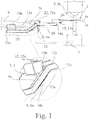
- the switching signal is transmitted to a control device 7 of a machine tool 8, which control device 7 and machine tool 8 also in the Fig. 1 are shown.
- the transmitting device 6 can be both a device for wireless transmission and, as here, a wired transmission arrangement 6a.
- the machine tool 8 is a riveting machine 8a in the present embodiment.
- the transmitting device 6 can also be set up to receive signals and data from the control device 7.
- the holding device could be adapted to at an attachment point on or at the machine tool 8 z. B. to be mounted pivotally.
- the holding device is portable, namely specifically by gripping the handle assembly 3 by the user 4. This facilitates the use and increases the flexibility of the holding device.
- the handle assembly 3 is adapted for ambidextrous gripping by the user 4. On the one hand, this facilitates the carrying and aligning of the holding device and further ensures that the user 4 actually uses both hands for gripping the handle arrangement 3.
- the handle assembly 3 has two particular spaced individual handles 9a, b for each hand 9c of the user 4. These individual handles 9a, b are specially set up for grasping by a respective hand 9c. Thus, a certain position of the hands is predetermined by the handle assembly 3.
- the push-button arrangement 5 is preferably arranged such that an actuation by the user 4 requires a particularly ambidextrous gripping of the handle arrangement 3 by the user 4.
- this ambidextrous gripping requires embracing the two individual handles 9a, b by the respective one hand 9c of the user 4.
- the functionality for gripping the holding device and that for generating the switching signal are combined in that the probe assembly 5 forms a preferably detachable component of the handle assembly 3.
- the probe assembly 5 forms a preferably detachable component of the handle assembly 3.
- z. B. comprising the approval and release switch already mentioned above, used and in the structure then purely mechanical handle assembly 3 are used.
- the probe assembly 5 has a Schofingertaster 10a and a Maufingertaster 10b, which are actuated by different fingers of the same hand of the user 4. It can - as in the embodiment shown - the Maufingertaster 10b for actuation by a thumb of this hand and a Heilfingertaster 10a for actuation by in particular the middle and ring fingers, possibly also be provided by the index finger, the same hand. Alternatively, a Schofingertaster 10a may be provided for actuation by the index finger and turn a Veryfingertaster 10b for actuation by means and ring finger.
- both the main finger button 10a and the sub finger button 10b would be placed on the same side of the respective single handle 9a, b instead of - as in the present case - on opposite sides of the respective single handle 9a, b.
- the assignment of a button as Hauptfingertaster 10a or as Maufingertaster 10b is arbitrary.
- the probe arrangement 5 has an elongated feeler device 11a, b and the main finger pushbutton 10a and the auxiliary finger pushbutton 10b are arranged offset from one another along a probe longitudinal axis 12a, b of the feeler device 11a, b, which is specifically described in US Pat Fig. 1 is shown.
- the push-button device 11a, b forms part of a single handle 9a, b or is arranged in a single handle 9a, b.
- a “push-button device” can here and below be understood as meaning both a separate device with push-buttons with its own push-button housing and a device with push-buttons, which is formed integrally or monolithically with the respective individual handle 9a, b and thus shares a housing with it ,
- the push-button device can also be detachably arranged in the single handle 9a, b.
- the probe arrangement 5 In order to further reduce the risk of unintentional triggering of the switching signal, it is preferably provided that the probe arrangement 5 generates the switching signal only when the main finger button 10a and the sub finger button 10b are actuated in particular simultaneously.
- the simultaneous operation of the Hauptfingertasters 10a and the Maufingertasters 10b, a grasping of the respective probe device 11a, b presuppose.
- the probe arrangement 5 has two probe devices 11a, b.
- the push-button devices 11a, b are arranged here in particular on a respective individual handle 9a, b and in particular within the respective individual handle 9a, b.
- both Taster devices 11a, b each have a Hauptfingertaster 10a and a Maufingertaster 10b.
- the trigger safety is further increased if it is provided that the probe assembly 5 generates the switching signal only if a particular simultaneous operation of both probe devices 11a, b takes place and preferably only when the Hauptfingertaster 10a both Tasteroara 11a, b and the Maufingertaster 10b at least one push-button device 11a, b - accordingly, a total of at least three buttons - are operated.
- it is arbitrary, whether it is the Crowfingertaster 10b of one or the other Taster réelles 11a, b.
- each push-button device 11a, b can also each push-button device 11a, b more than two fingers, so not only a Hauptfingertaster 10a and a Maufingertaster 10b, then also the operation of more than two finger buttons and especially of all finger buttons both push buttons 11a, b to trigger the switching signal may be required.
- a peculiarity of safety switches which include the above-mentioned release and consent switches, is that the individual push-buttons have an actuation path with a plurality of actuation ranges.
- a risky processing step can only be initiated if the corresponding button is held or actuated in a medium operating range. In this way, it is ensured that both a complete release of the button and a stronger operation - because both reactions reflexively in a moment of shock conceivable - breaks off the risky processing step and z. B. leads to an emergency stop.
- the actuation of the push-button arrangement 5 takes place along an actuation path with at least two actuation areas.
- This variant can advantageously be specified by the fact that the actuation areas have an active area and an inactive area and that the switching signal is generated only when actuated in the active area. Specifically - in the presence of multiple buttons - the switching signal is generated only in a particular simultaneous operation of more than one button in the active area. If a plurality of push-button devices 11a, b are present, it may accordingly be preferred that the switching signal is generated in the active region only when the main finger buttons 10a of both push-button devices 11a, b and the auxiliary finger button 10b of at least one push-button device 11a, b are actuated.
- the holding device has a frame 13 with two substantially parallel arranged and substantially elongated carriers 13a, b. It is preferred that - as shown in the embodiment - the receiving assembly 2 is arranged at each adjacent longitudinal end 14a, b of the two carriers 13a, b. Under the respectively adjacent longitudinal end 14a, b of both carriers in the present sense is to be understood a pair of a first longitudinal end 14a of a first carrier 13a and a second longitudinal end 14b of a second carrier 13b, which - based on the parallel orientation of the carrier 13a, b - pointing in the same direction.
- the receiving arrangement 2 may have a fixing arrangement 15 for fastening the test sheet 1, wherein the fixing arrangement 15 in the present case is a clamping punch arrangement 15a.
- the handle arrangement 3 is arranged on a respective grip region 17a, b of the carriers 13a, b. Due to the substantially elongated design, the carriers 13a, b have a longitudinal axis 16. This respective gripping region 17a, b can then also - as shown in the drawing - each be arranged substantially centrally with respect to this longitudinal axis 16. Likewise, it is preferred that the respective grip area 17a, b at an angle to a longitudinal axis 16 of the carrier 13 a, b is arranged.
- the resulting "gooseneck shape" of the carrier 13a, b which also emerges from the drawing, does not limit the substantially elongated design of the carrier 13a, b or a contradiction to the presence of a longitudinal axis 16. It is also preferable that the individual handles 9a , B are arranged in each case on a carrier 13a, b.
- a support distance 20 from the forearm supports 19a, b to the grip region 17a, b along the longitudinal axis 16 essentially corresponds to a receiving distance 21 from the receiving arrangement 2 to the grip region 17a, b along the longitudinal axis 16.
- Such underarm supports 19a, b facilitate carrying of heavier test sheets 1 with the holding device.
- the holding arrangement has a display device 22 with illuminated displays 22a for indicating an actuation state of the push-button arrangement 5.
- This display device 22 can also reproduce signals from the control device 7 of the machine tool 8.
- the holding arrangement comprises a cover assembly 23, which covers the handle assembly and in particular the individual handles 9a, b in the direction of the receiving device 2.
- the cover assembly 23 at least partially form a cover plane in which the longitudinal axis 16 is located.
- a proposed machine tool 8 for metalworking, and here in particular for producing riveted joints has an end effector 24, which is set up here especially for setting rivets.
- the proposed machine tool 8 also has a control device 7 for driving the end effector 24 and a proposed holding device.
- the proposed machine tool is characterized in that the control device 7 is adapted to trigger the end effector 24 to trigger the switching signal. Consequently, in the present embodiment, the production of a riveted joint on the test sheet 1 is triggered. Further preferred embodiments of the proposed machine tool result arising from the corresponding features and configurations of the proposed holding device.
Description
Die Erfindung betrifft eine Haltevorrichtung für ein Testblech gemäß dem Gegenstand von Anspruch 1 und eine Werkzeugmaschine zur Metallbearbeitung gemäß dem Gegenstand von Anspruch 15. Aus
Bei Werkzeugmaschinen zur Metallbearbeitung und speziell bei Nietmaschinen zum Setzen von Nietverbindungen gibt es regelmäßig den Wunsch, den Metallbearbeitungsvorgang bzw. den Nietsetzvorgang probeweise an einer Grundwerkstoffprobe durchzuführen. Diese Grundwerkstoffprobe wird in der Regel durch ein Blech oder durch Blechpakete gebildet, welches Blech oder Blechpaket auch als Testblech oder Testcoupon bezeichnet wird.In the case of machine tools for metalworking and, in particular, riveting machines for setting riveted joints, there is a regular desire to carry out the metalworking process or the rivet setting process on a sample of base material on a trial basis. This base material sample is usually formed by a sheet or by laminated cores, which sheet or laminated core is also referred to as a test sheet or test coupon.
Speziell im Bereich der Luft- und Raumfahrtproduktion ist häufig die Bearbeitung sehr großer Werkstücke vorgesehen, sodass ein gegenüber diesen Werkstücken kleiner Testcoupon nicht ohne Weiteres durch die für die großen Werkstücke vorgesehenen Positioniervorrichtungen gehandhabt werden kann. Aus diesem Grunde wird gerade in diesem Bereich regelmäßig der Testcoupon manuell von einem Benutzer derart in einem Arbeitsbereich der Werkzeugmaschine positioniert, dass der Metallbearbeitungsschritt an dem Testcoupon vorgenommen werden kann.Particularly in the field of aerospace production, the machining of very large workpieces is often provided, so that a test coupon that is smaller than these workpieces can not easily be handled by the positioning devices provided for the large workpieces. For this reason, it is precisely in this area that the test coupon is regularly positioned manually by a user in a working area of the machine tool in such a way that the metalworking step can be performed on the test coupon.
Dieser Ansatz ist in verschiedener Hinsicht problematisch. Einerseits erfordert er, dass der Benutzer sich insbesondere mit seinen Händen in den Arbeitsbereich der Maschine begibt, was im regulären Betrieb gerade verhindert werden soll und ein Arbeitsunfallrisiko darstellt. Auch um einen solchen Eintritt eines Benutzers in den Arbeitsbereich oder überhaupt eine Annäherung daran zu vermeiden, setzt das Auslösen des Metallbearbeitungsschrittes voraus, dass der entsprechende Benutzer regelmäßig mit beiden Händen eine Steueranordnung der Werkzeugmaschine bedient. Diese Steueranordnung ist in Bezug auf den Arbeitsbereich regelmäßig so angeordnet, dass der die Steueranordnung bedienende Benutzer sich in hinreichendem Abstand zu dem Arbeitsbereich befindet, weswegen er regelmäßig nicht gleichzeitig den Testcoupon in den Arbeitsbereich halten kann. Daher sind zum Vornehmen des Metallbearbeitungsschrittes an dem Testcoupon zwei Personen notwendig. Die Notwendigkeit der Abstimmung zwischen diesen beiden Personen erhöht die Wahrscheinlichkeit eines Auslösens des Metallbearbeitungsschrittes zur Unzeit und damit auch das Arbeitsunfallrisiko.This approach is problematic in several ways. On the one hand, it requires that the user in particular goes with his hands in the work area of the machine, which is just to be prevented in regular operation and represents an occupational accident risk. Also, to avoid such entry of a user into the work area or at all an approximation to it, the triggering of the metalworking step requires that the corresponding user regularly operates with both hands a control arrangement of the machine tool. This control arrangement is regularly arranged with respect to the work area such that the user operating the control arrangement is located at a sufficient distance from the work area, which is why he can not regularly hold the test coupon in the work area at the same time. Therefore, two persons are required to perform the metalworking step on the test coupon. The need for coordination between These two persons increase the likelihood of triggering the metalworking step at an inopportune time and thus also the risk of accidents at work.
Hiervon ausgehend besteht das Problem der Erfindung darin, das Vornehmen eines probeweisen Metallbearbeitungsschrittes an einem Testblech durch eine Werkzeugmaschine sowohl einfacher als auch sicherer zu gestalten.On this basis, the problem of the invention is to make the making of a trial metal working step on a test sheet by a machine tool both simpler and safer.
Das genannte Problem wird für eine Haltevorrichtung für ein Testblech durch den Gegenstand von Anspruch 1 und für eine Werkzeugmaschine zur Metallbearbeitung durch den Gegenstand von Anspruch 15 gelöst.The above problem is solved for a holding device for a test sheet by the subject matter of
Wesentlich für die Erfindung ist die Erkenntnis, dass eine Haltevorrichtung sowohl mit einer Aufnahmeanordnung für das Testblech, durch welche das aufgenommene Testblech an der richtigen Stelle, mit der richtigen Ausrichtung und unter Wahrung eines hinreichenden Abstandes des Benutzers zum Arbeitsbereich in diesem positioniert werden kann, als auch mit einer Tasteranordnung zum Auslösen des Metallbearbeitungsschrittes an der Werkzeugmaschine versehen werden kann. Auf diese Weise ist es einem einzelnen Benutzer möglich, das Testblech sicher im Arbeitsbereich der Werkzeugmaschine zu positionieren und dabei gleichzeitig das Auslösen des Metallbearbeitungsschrittes unter eigener Kontrolle zu haben. Auf diese Weise wird das Durchführen des Metallbearbeitungsschrittes an dem Testblech sicherer und kann durch eine einzelne Person ausgeführt werden.Essential to the invention is the recognition that a holding device can be positioned both with a receiving arrangement for the test sheet, by which the recorded test sheet in the right place, with the correct orientation and while maintaining a sufficient distance of the user to the work area in this can also be provided with a probe arrangement for triggering the metalworking step on the machine tool. In this way, it is possible for a single user to safely position the test sheet in the working area of the machine tool while at the same time having the triggering of the metalworking step under its own control. In this way, performing the metalworking step on the test sheet becomes safer and can be performed by a single person.
Die bevorzugten Ausgestaltungen der Unteransprüche 3 bis 5 sowie 8 und 9 betreffen das Erfordernis, ein beidhändiges Greifen der Haltevorrichtung zu gewährleisten, sodass praktisch ausgeschlossen werden kann, dass eine Hand des Benutzers der Haltevorrichtung sich bei Auslösen des Metallbearbeitungsschrittes in einem Gefahrenbereich der Werkzeugmaschine befindet.The preferred embodiments of the
Aus dem Stand der Technik sind bereits tragbare Tasteranordnungen zur Freigabe von sicherheitskritischen Vorgängen, z. B. sogenannte Zustimmungs- oder Freigabeschalter, bekannt. Die bevorzugte Ausgestaltung des Unteranspruchs 6 sieht nun die Möglichkeit vor, solche Tasteranordnungen als Komponente in einer vorschlagsgemäßen Haltevorrichtung zu verwenden. Auf diese Weise kann die von den bekannten Tasteranordnungen gewährleistete und in der Regel zertifizierte Verlässlichkeit für die vorschlagsgemäße Lösung eingesetzt werden.From the state of the art are already portable button assemblies for release of safety-critical operations, eg. B. so-called approval or release switch known. The preferred embodiment of the subclaim 6 now provides the possibility to use such probe arrangements as a component in a proposed holding device. This way you can the guaranteed by the known probe arrangements and usually certified reliability for the proposed solution can be used.
Der Unteranspruch 11 wiederum betrifft eine Ausgestaltung der Tasteranordnung, welche jeweils ein vollständiges Umgreifen der Tasteranordnung durch den Benutzer zur Betätigung erforderlich macht.The dependent claim 11 in turn relates to an embodiment of the probe assembly, which makes a complete encompassing the probe assembly required by the user to operate.
Die Unteransprüche 12 und 13 sehen eine bevorzugte Variante vor, nach welcher die Tasteranordnung einen Betätigungsweg mit unterschiedlichen Betätigungsbereichen aufweist. Zum Auslösen des Metallbearbeitungsschrittes ist dann eine Betätigung in einem definierten Betätigungsbereich erforderlich.The
Der bevorzugte Unteranspruch 14 betrifft eine ergonomisch besonders vorteilhafte Konstruktion der Haltevorrichtung, welche das genaue Positionieren des Testbleches mit gleichzeitig sehr guter Kontrolle über das Auslösen des Metallbearbeitungsschrittes erlaubt.The preferred dependent claim 14 relates to an ergonomically particularly advantageous construction of the holding device, which allows the exact positioning of the test sheet with at the same time very good control over the triggering of the metalworking step.
Weitere Einzelheiten, Merkmale, Ziele und Vorteile der vorliegenden Erfindung werden nachfolgend anhand einer lediglich ein Ausführungsbeispiel wiedergebenden Zeichnung näher erläutert. In der Zeichnung zeigt
- Fig. 1
- eine Seitenansicht auf eine Werkzeugmaschine zur Metallbearbeitung mit einer vorschlagsgemäßen Haltevorrichtung,
- Fig. 2
- eine Perspektivansicht von schräg oben auf die vorschlagsgemäße Haltevorrichtung der
Fig. 1 und - Fig. 3
- eine Perspektivansicht von schräg unten auf die vorschlagsgemäße Haltevorrichtung der
Fig. 1 .
- Fig. 1
- a side view of a machine tool for metalworking with a proposed holding device,
- Fig. 2
- a perspective view obliquely from above of the proposed holding device of
Fig. 1 and - Fig. 3
- a perspective view obliquely from below of the proposed holding device of
Fig. 1 ,
Die vorschlagsgemäße Haltevorrichtung für ein Testblech 1 weist eine Aufnahmeanordnung 2 zum insbesondere formschlüssigen Eingriff mit dem Testblech 1 auf. Bei dem Testblech 1 kann es sich um ein beliebiges, insbesondere flächiges Werkstück oder um ein solches Blechpaket handeln, an dem probeweise ein Metallbearbeitungsschritt durchgeführt werden soll. Im vorliegenden Beispiel handelt es sich bei dem Testblech 1 um zwei einzelne und übereinandergestapelte Aluminiumbleche 1a, b, welche mit einer zu setzenden Nietverbindung miteinander verbunden werden sollen. Die Aufnahmeanordnung 2 ist dazu eingerichtet, einen Eingriff mit dem Testblech 1 herzustellen, durch welchen Eingriff das Testblech 1 gehalten, hochgehoben und positioniert werden kann. Zusätzlich zu diesem bevorzugt formschlüssigen Eingriff kann ein Herausfallen des Testblechs 1 aus der Aufnahmeanordnung 2 auch noch mit weiteren Maßnahmen verhindert werden, welche untenstehend noch genauer beschrieben werden.The proposed holding device for a
Die vorschlagsgemäße Haltevorrichtung weist ferner eine starr mit der Aufnahmeanordnung 2 verbundene Griffanordnung 3 für einen Benutzer 4 zum Positionieren des Testblechs 1 auf. Das bedeutet, dass der Benutzer 4 die Griffanordnung 3 greifen und durch Bewegen der Griffanordnung 3 dank der starren Verbindung die Aufnahmeanordnung 2 - und mit ihr das Testblech 1, mit dem es in Eingriff steht - analog bewegen und damit auch ausrichten und positionieren kann.The proposed holding device further comprises a
Daneben weist die vorschlagsgemäße Haltevorrichtung eine Tasteranordnung 5 zum Erzeugen eines Schaltsignals basierend auf einer Betätigung durch den Benutzer 4 auf. Vorzugsweise erzeugt die Tasteranordnung 5 das Schaltsignal, wenn die Tasteranordnung 5 durch den Benutzer 4, insbesondere durch Drücken, betätigt wird.In addition, the proposed holding device on a button assembly 5 for generating a switching signal based on an operation by the
Gemäß einer bevorzugten Ausführungsform weist die Haltevorrichtung eine Sendevorrichtung 6 zum Übertragen des Schaltsignals auf. Vorzugsweise wird das Schaltsignal an eine Steuereinrichtung 7 einer Werkzeugmaschine 8 übertragen, welche Steuereinrichtung 7 und Werkzeugmaschine 8 ebenfalls in der
Prinzipiell könnte die Haltevorrichtung dazu eingerichtet sein, an einem Befestigungspunkt an oder bei der Werkzeugmaschine 8 z. B. schwenkbar angebracht zu werden. Bevorzugt ist jedoch, dass die Haltevorrichtung tragbar ist, und zwar speziell durch Greifen der Griffanordnung 3 durch den Benutzer 4. Das erleichtert die Benutzung und erhöht die Flexibilität der Haltevorrichtung.In principle, the holding device could be adapted to at an attachment point on or at the machine tool 8 z. B. to be mounted pivotally. However, it is preferred that the holding device is portable, namely specifically by gripping the
Bevorzugt und wie in dem Ausführungsbeispiel dargestellt ist die Griffanordnung 3 zum beidhändigen Greifen durch den Benutzer 4 eingerichtet. Dies erleichtert einerseits das Tragen und Ausrichten der Haltevorrichtung und sorgt weiter dafür, dass der Benutzer 4 auch tatsächlich beide Hände zum Greifen der Griffanordnung 3 verwendet. Dies kann dadurch verwirklicht werden, dass die Griffanordnung 3 zwei insbesondere beabstandete Einzelgriffe 9a, b für jeweils eine Hand 9c des Benutzers 4 aufweist. Diese Einzelgriffe 9a, b sind speziell für ein Umgreifen durch jeweils eine Hand 9c eingerichtet. Damit ist eine bestimmte Position der Hände durch die Griffanordnung 3 vorgegeben.Preferably, and as shown in the embodiment, the
Damit diese Position der Hände des Benutzers 4 auch zum Zeitpunkt des Erzeugens des Schaltsignals gewährleistet ist, ist vorzugsweise die Tasteranordnung 5 so angeordnet, dass eine Betätigung durch den Benutzer 4 ein insbesondere beidhändiges Greifen der Griffanordnung 3 durch den Benutzer 4 voraussetzt. Hier ist weiter bevorzugt, dass dieses beidhändige Greifen ein Umgreifen der beiden Einzelgriffe 9a, b durch die jeweils eine Hand 9c des Benutzers 4 voraussetzt.So that this position of the hands of the
Auf vorteilhafte Art und Weise werden die Funktionalität zum Greifen der Haltevorrichtung und diejenige zum Erzeugen des Schaltsignals dadurch vereint, dass die Tasteranordnung 5 einen vorzugsweise lösbaren Bestandteil der Griffanordnung 3 bildet. Auf diese Weise - welche untenstehend noch genauer beschrieben wird - kann eine bereits "von der Stange" (off the shelf) verfügbare Tasteranordnung 5, z. B. umfassend die oben bereits erwähnten Zustimmungs- und Freigabeschalter, verwendet und in die in ihrem Aufbau dann rein mechanische Griffanordnung 3 eingesetzt werden.Advantageously, the functionality for gripping the holding device and that for generating the switching signal are combined in that the probe assembly 5 forms a preferably detachable component of the
Um den erhöhten Sicherheitsanforderungen beim Erzeugen des Schaltsignals gerecht zu werden und insbesondere eine versehentliche Betätigung zu vermeiden, ist bevorzugt vorgesehen, dass die Tasteranordnung 5 einen Hauptfingertaster 10a und einen Nebenfingertaster 10b aufweist, die jeweils durch unterschiedliche Finger derselben Hand des Benutzers 4 betätigbar sind. Dabei kann - wie in dem gezeigten Ausführungsbeispiel - der Nebenfingertaster 10b zur Betätigung durch einen Daumen dieser Hand und ein Hauptfingertaster 10a zur Betätigung durch insbesondere den Mittel- und Ringfinger, ggf. auch durch den Zeigefinger, derselben Hand vorgesehen sein. Alternativ kann auch ein Hauptfingertaster 10a zur Betätigung durch den Zeigefinger und wiederum ein Nebenfingertaster 10b zur Betätigung durch Mittel- und Ringfinger vorgesehen sein. In diesem Fall wären sowohl der Hauptfingertaster 10a als auch der Nebenfingertaster 10b auf derselben Seite des jeweiligen Einzelgriffs 9a, b platziert anstatt - wie im vorliegenden Fall - auf gegenüberliegenden Seiten des jeweiligen Einzelgriffs 9a, b. Im Prinzip ist dabei die Zuordnung eines Tasters als Hauptfingertaster 10a oder als Nebenfingertaster 10b beliebig.In order to meet the increased safety requirements when generating the switching signal and in particular to avoid accidental actuation, it is preferably provided that the probe assembly 5 has a
Ebenso ist es bevorzugt, dass die Tasteranordnung 5 ein längliches Tastergerät 11a, b aufweist und der Hauptfingertaster 10a und der Nebenfingertaster 10b zueinander versetzt entlang einer Tasterlängsachse 12a, b des Tastergeräts 11a, b angeordnet sind, was speziell in der
Um das Risiko eines unbeabsichtigten Auslösens des Schaltsignals noch weiter zu verringern ist bevorzugt vorgesehen, dass die Tasteranordnung 5 das Schaltsignal nur dann erzeugt, wenn der Hauptfingertaster 10a und der Nebenfingertaster 10b insbesondere gleichzeitig betätigt werden. Weiter insbesondere kann hierbei die gleichzeitige Betätigung des Hauptfingertasters 10a und des Nebenfingertasters 10b ein Umgreifen des jeweiligen Tastergeräts 11a, b voraussetzen.In order to further reduce the risk of unintentional triggering of the switching signal, it is preferably provided that the probe arrangement 5 generates the switching signal only when the
Wie in dem Ausführungsbeispiel der
Hierauf aufbauend wird die Auslösesicherheit noch weiter erhöht, wenn vorgesehen ist, dass die Tasteranordnung 5 das Schaltsignal nur dann erzeugt, wenn eine insbesondere gleichzeitige Betätigung an beiden Tastergeräten 11a, b erfolgt und vorzugsweise nur dann, wenn der Hauptfingertaster 10a beider Tastergeräte 11a, b und der Nebenfingertaster 10b mindestens eines Tastergeräts 11a, b - entsprechend also insgesamt mindestens drei Taster - betätigt werden. Vorzugsweise ist es dabei beliebig, ob es sich um den Nebenfingertaster 10b des einen oder anderen Tastergeräts 11a, b handelt. Auf diese Weise kann durch eine längere Betätigung der Hauptfingertaster 10a ein Grundbereitschaftszustand zum Erzeugen des Schaltsignals hergestellt werden, in welchem bereits die korrekte Platzierung der Hände des Benutzers 4 an der Tasteranordnung 5 gewährleistet. Zur präzisen Bestimmung des genauen Erzeugungszeitpunktes des Schaltsignals reicht dann die Betätigung eines einzelnen Nebenfingertasters 10b, wobei die spezielle Wahl des Tastergeräts 11a, b dann einfach davon abhängig sein kann, ob der Benutzer 4 Rechtshänder oder Linkshänder ist.Based on this, the trigger safety is further increased if it is provided that the probe assembly 5 generates the switching signal only if a particular simultaneous operation of both
Es kann auch jedes Tastergerät 11a, b mehr als zwei Fingertaster, also nicht nur einen Hauptfingertaster 10a und einen Nebenfingertaster 10b, aufweisen, wobei dann auch die Betätigung von mehr als zwei Fingertastern und speziell von allen Fingertastern beider Tastergeräte 11a, b zum Auslösen des Schaltsignals erforderlich sein kann.It can also each push-
Eine Besonderheit bei Sicherheitsschaltern, zu denen die oben erwähnten Freigabe- und Zustimmungsschalter zählen, ist die, dass die einzelnen Taster einen Betätigungsweg mit mehreren Betätigungsbereichen aufweist. Bei Zustimmungsschaltern kann ein riskanter Bearbeitungsschritt nur dann eingeleitet werden, wenn der entsprechende Taster in einem mittleren Betätigungsbereich gehalten bzw. betätigt wird. Auf diese Weise ist gewährleistet, dass sowohl ein völliges Loslassen des Tasters als auch eine stärkere Betätigung - denn es sind beide Reaktionen reflexhaft in einer Schrecksekunde denkbar - den riskanten Bearbeitungsschritt abbricht und z. B. zu einer Notausschaltung führt. Dementsprechend ist es auch vorliegend bevorzugt, dass die Betätigung der Tasteranordnung 5 entlang eines Betätigungswegs mit mindestens zwei Betätigungsbereichen erfolgt. Speziell können dabei der Hauptfingertaster 10a und/oder der Nebenfingertaster 10b, insbesondere beider Tastergeräte 11a, b, jeweils mindestens zwei Betätigungsbereiche - und damit wie im oben genannten Beispiel des Sicherheitsschalters auch drei Betätigungsbereiche - aufweisen.A peculiarity of safety switches, which include the above-mentioned release and consent switches, is that the individual push-buttons have an actuation path with a plurality of actuation ranges. In the case of consent switches, a risky processing step can only be initiated if the corresponding button is held or actuated in a medium operating range. In this way, it is ensured that both a complete release of the button and a stronger operation - because both reactions reflexively in a moment of shock conceivable - breaks off the risky processing step and z. B. leads to an emergency stop. Accordingly, it is also presently preferred that the actuation of the push-button arrangement 5 takes place along an actuation path with at least two actuation areas. Specifically, the
Diese Variante kann vorteilhafterweise dadurch präzisiert werden, dass die Betätigungsbereiche einen Aktivbereich und einen Inaktivbereich aufweisen und dass das Schaltsignal nur bei einer Betätigung in dem Aktivbereich erzeugt wird. Speziell wird - beim Vorhandensein mehrerer Taster - das Schaltsignal nur bei einer insbesondere gleichzeitigen Betätigung von mehr als einem Taster in dem Aktivbereich erzeugt. Wenn mehrere Tastergeräte 11a, b vorhanden sind, kann es entsprechend bevorzugt sein, dass das Schaltsignal nur bei einer Betätigung der Hauptfingertaster 10a beider Tastergeräte 11a, b und des Nebenfingertasters 10b mindestens eines Tastergeräts 11a, b in dem Aktivbereich erzeugt wird.This variant can advantageously be specified by the fact that the actuation areas have an active area and an inactive area and that the switching signal is generated only when actuated in the active area. Specifically - in the presence of multiple buttons - the switching signal is generated only in a particular simultaneous operation of more than one button in the active area. If a plurality of push-
Im Hinblick auf die konstruktive Ausgestaltung der vorschlagsgemäßen Haltevorrichtung ist es bevorzugt, dass die Haltevorrichtung einen Rahmen 13 mit zwei im Wesentlichen parallel angeordneten und im Wesentlichen länglich ausgebildeten Trägern 13a, b aufweist. Dabei ist es bevorzugt, dass - wie im Ausführungsbeispiel dargestellt - die Aufnahmeanordnung 2 an jeweils einem benachbarten Längsende 14a, b beider Träger 13a, b angeordnet ist. Unter dem jeweils benachbarten Längsende 14a, b beider Träger im vorliegenden Sinne ist ein Paar aus einem ersten Längsende 14a eines ersten Trägers 13a und einem zweiten Längsende 14b eines zweiten Trägers 13b zu verstehen, welche - bezogen auf die parallele Ausrichtung der Träger 13a, b - in dieselbe Richtung weisen. Für eine besonders zuverlässige Aufnahme des Testblechs 1 kann die Aufnahmeanordnung 2 eine Fixieranordnung 15 zum Befestigen des Testblechs 1 aufweisen, bei welcher Fixieranordnung 15 es sich vorliegend um eine Klemmstempelanordnung 15a handelt.With regard to the structural design of the proposed holding device, it is preferred that the holding device has a
Weiter ist bevorzugt vorgesehen, dass die Griffanordnung 3 an einem jeweiligen Griffbereich 17a, b der Träger 13a, b angeordnet ist. Durch die im Wesentlichen längliche Ausbildung weisen die Träger 13a, b eine Längsachse 16 auf. Dieser jeweilige Griffbereich 17a, b kann dann auch - wie in der Zeichnung dargestellt - jeweils im Wesentlichen mittig bezogen auf diese Längsachse 16 angeordnet sein. Ebenso ist es bevorzugt, dass der jeweilige Griffbereich 17a, b winklig zu einer Längsachse 16 der Träger 13a, b angeordnet ist. Die dadurch entstehende "Schwanenhalsform" der Träger 13a, b, welche auch aus der Zeichnung hervorgeht, bedeutet keine Einschränkung der im Wesentlichen länglichen Ausbildung der Träger 13a, b oder einen Widerspruch zu dem Vorhandensein einer Längsachse 16. Bevorzugt ist ebenso, dass die Einzelgriffe 9a, b an jeweils einem Träger 13a, b angeordnet sind.Furthermore, it is preferably provided that the
Weitere vorteilhafte konstruktive Ausgestaltungen sehen vor, dass an benutzerseitigen Längsenden der Träger 13a, b - Benutzerenden 18a, b - Unterarmauflagen 19a, b zum Stützen eines jeweiligen Benutzerarmes vorgesehen sind. Vorzugsweise entspricht dabei eine Auflageentfernung 20 von den Unterarmauflagen 19a, b zu dem Griffbereich 17a, b entlang der Längsachse 16 im Wesentlichen einer Aufnahmeentfernung 21 von der Aufnahmeanordnung 2 zu dem Griffbereich 17a, b entlang der Längsachse 16. Solche Unterarmauflagen 19a, b erleichtern das Tragen von schwereren Testblechen 1 mit der Haltevorrichtung.Further advantageous structural embodiments provide that on user-side longitudinal ends of the
Ebenso ist es bevorzugt, dass die Halteanordnung eine Anzeigevorrichtung 22 mit Leuchtanzeigen 22a zur Anzeige eines Betätigungszustandes der Tasteranordnung 5 aufweist. Diese Anzeigevorrichtung 22 kann auch Signale von der Steuereinrichtung 7 der Werkzeugmaschine 8 wiedergeben. Schließlich ist vorzugsweise und wie in der Zeichnung wiedergegeben vorgesehen, dass die Halteanordnung eine Abdeckanordnung 23 aufweist, welche die Griffanordnung und insbesondere die Einzelgriffe 9a, b in Richtung der Aufnahmeanordnung 2 abdeckt. Insbesondere kann die Abdeckanordnung 23 zumindest bereichsweise eine Abdeckebene bilden, in welcher auch die Längsachse 16 liegt.It is likewise preferred that the holding arrangement has a display device 22 with illuminated
Eine vorschlagsgemäße Werkzeugmaschine 8 zur Metallbearbeitung, und hier insbesondere zum Herstellen von Nietverbindungen, weist einen Endeffektor 24 auf, welcher hier speziell zum Setzen von Nieten eingerichtet ist. Die vorschlagsgemäße Werkzeugmaschine 8 weist ebenso eine Steuereinrichtung 7 zum Ansteuern des Endeffektors 24 sowie eine vorschlagsgemäße Haltevorrichtung auf. Die vorschlagsgemäße Werkzeugmaschine ist dadurch gekennzeichnet, dass die Steuereinrichtung 7 dazu eingerichtet ist, den Endeffektor 24 auf das Schaltsignal auslösend anzusteuern. Folglich wird im vorliegenden Ausführungsbeispiel das Herstellen einer Nietverbindung an dem Testblech 1 ausgelöst. Weitere bevorzugte Ausgestaltungen der vorschlagsgemäßen Werkzeugmaschine ergeben sich aus den entsprechenden Merkmalen und Ausgestaltungen der vorschlagsgemäßen Haltevorrichtung.A proposed machine tool 8 for metalworking, and here in particular for producing riveted joints, has an
Claims (15)
- Holding device for a test sheet (1), with a receiving arrangement (2) for engagement with the test sheet (1), a handle arrangement (3) connected rigidly to the receiving arrangement (2) for a user (4) for positioning the test sheet (1), characterized by a pushbutton arrangement (5) for producing a switching signal on the basis of an actuation by the user (4).
- Holding device according to Claim 1, characterized in that the holding device comprises a transmitting device (6) for transmitting the switching signal, preferably to a controller (7) of a machine tool (8).
- Holding device according to Claim 1 or 2, characterized in that the holding device is portable, in particular by the user (4) gripping the handle arrangement (3).
- Holding device according to one of Claims 1 to 3, characterised in that the handle arrangement (3) is configured for gripping by the user (4) with both hands, preferably wherein the handle arrangement (3) has two, in particular spaced-apart, individual handles (9a, b), furthermore in particular for grasping, by one hand (9c) each of the user (4).
- Holding device according to one of Claims 1 to 4, characterized in that the pushbutton arrangement (5) is arranged in such a manner that an actuation by the user (4) requires in particular gripping of the handle arrangement (3) by the user (4) with both hands, and preferably requires grasping of the two individual handles (9a, b) by one hand each (9c) of the user (4).
- Holding device according to Claim 5, characterized in that the pushbutton arrangement (5) forms a, preferably releasable, part of the handle arrangement (3).
- Holding device according to one of Claims 1 to 6, characterised in that the pushbutton arrangement (5) has a main finger pushbutton (10a) and a secondary finger pushbutton (10b) which are both actuable by different fingers of the same hand of the user (4), wherein the pushbutton arrangement (5) has an elongate pushbutton unit (11a, b), and the main finger pushbutton (10a) and the secondary finger pushbutton (10b) are arranged offset with respect to each other along a pushbutton longitudinal axis (12a, b) of the pushbutton unit (11a, b), in particular in that the pushbutton unit (11a, b) forms part of an individual handle (9a, b) or is arranged in an individual handle (9a, b).
- Holding device according to Claim 7, characterized in that the pushbutton arrangement (5) produces the switching signal only if the main finger pushbutton (10a) and the secondary finger pushbutton (10b) are actuated in particular simultaneously, preferably in that the simultaneous actuation of the main finger pushbutton (10a) and of the secondary finger pushbutton (10b) requires grasping of the respective pushbutton unit (11a, b).
- Holding device according to one of Claims 1 to 8, characterized in that the pushbutton arrangement (5) has two pushbutton units (11a, b), preferably wherein the pushbutton units (12a, b) are arranged on one individual handle (9a, b) each, in particular within one individual handle (9a, b) each.
- Holding device according to Claim 9, characterized in that the two pushbutton units (11a, b) each have a main finger pushbutton (10a) and a secondary finger pushbutton (10b).
- Holding device according to Claim 9 or 10, characterized in that the pushbutton arrangement (5) produces the switching signal only if an in particular simultaneous actuation takes place on both pushbutton units (11a, b), preferably produces the switching signal only if the main finger pushbutton (10a) of the two pushbutton units (11a, b) and the secondary finger pushbutton (10b) of at least one pushbutton unit (11a, b) are actuated.
- Holding device according to one of Claims 1 to 11, characterized in that the actuation of the pushbutton arrangement (5) takes places along an actuating path with at least two actuating regions, preferably wherein the main finger pushbutton (10a) and/or the secondary finger pushbutton (10b), in particular of the two pushbutton units (11a, b), each have at least two actuating regions.
- Holding device according to Claim 12, characterized in that the actuating regions have an active region and an inactive region, and in that the switching signal is produced only upon an actuation in the active region, preferably in that the switching signal is produced only if an in particular simultaneous actuation of the main finger pushbutton (10a) of the two pushbutton units (11a, b) and of the secondary finger pushbutton (10b) of at least one pushbutton unit (11a, b) in the active region takes place.
- Holding device according to one of Claims 1 to 13, characterized in that the holding device has a frame (13) with two supports (13a, b) which are arranged substantially parallel and are of substantially elongate design, preferably wherein the receiving arrangement (2) is arranged at an adjacent longitudinal end (14a, b) of each of the two supports (13a, b), in particular wherein the handle arrangement (3) is arranged on a respective handle region (17a, b) of the supports (13a, b), said handle region being angled in particular with respect to a longitudinal axis (16) of the supports (13a, b), furthermore preferably in that the individual handles (9a, b) are arranged on one support (13a, b) each.
- Machine tool (8) for metal working, in particular for producing rivet connections, with an end effector (24), in particular for setting rivets, a controller (7) for activating the end effector (24), and a holding device according to one of Claims 1 to 14, characterized in that the controller (7) is configured to activate the end effector (24) so as to trigger the switching signal.
Applications Claiming Priority (2)
| Application Number | Priority Date | Filing Date | Title |
|---|---|---|---|
| DE202014104915.0U DE202014104915U1 (en) | 2014-10-15 | 2014-10-15 | Holding device for a test sheet |
| PCT/EP2015/073888 WO2016059159A1 (en) | 2014-10-15 | 2015-10-15 | Holding device for a test sheet |
Publications (2)
| Publication Number | Publication Date |
|---|---|
| EP3207302A1 EP3207302A1 (en) | 2017-08-23 |
| EP3207302B1 true EP3207302B1 (en) | 2019-01-09 |
Family
ID=54329529
Family Applications (1)
| Application Number | Title | Priority Date | Filing Date |
|---|---|---|---|
| EP15781345.2A Active EP3207302B1 (en) | 2014-10-15 | 2015-10-15 | Holding device for a test sheet |
Country Status (8)
| Country | Link |
|---|---|
| US (1) | US10807149B2 (en) |
| EP (1) | EP3207302B1 (en) |
| CN (1) | CN107000033B (en) |
| DE (1) | DE202014104915U1 (en) |
| ES (1) | ES2718556T3 (en) |
| RU (1) | RU2674794C2 (en) |
| TR (1) | TR201905029T4 (en) |
| WO (1) | WO2016059159A1 (en) |
Families Citing this family (1)
| Publication number | Priority date | Publication date | Assignee | Title |
|---|---|---|---|---|
| DE202014104915U1 (en) | 2014-10-15 | 2016-01-18 | Brötje-Automation GmbH | Holding device for a test sheet |
Family Cites Families (16)
| Publication number | Priority date | Publication date | Assignee | Title |
|---|---|---|---|---|
| US1929484A (en) * | 1926-06-12 | 1933-10-10 | Prosperity Co Inc | Control for power mechanism |
| US1994414A (en) * | 1931-02-18 | 1935-03-12 | Prosperity Co Inc | Garment or ironing press |
| US3628357A (en) * | 1969-11-14 | 1971-12-21 | Verson Allsteel Press Co | Safety control circuit for presses and the like |
| SU651877A1 (en) * | 1977-09-13 | 1979-03-15 | Государственный Институт По Проектированию Технологии Монтажа Предприятий Химической Промышленности | Apparatus for feeding sheet stock into operation zone of machine for working metals by application of pressure |
| DE3918673A1 (en) * | 1989-06-08 | 1990-12-13 | Deere & Co | Safety operating switch for Brinel testing machine - uses foot operated switch comprising proximity sensor for releasing machine function |
| DE4016169A1 (en) * | 1990-05-19 | 1991-11-21 | Darko Dipl Ing Drazic | Contactless safety and control arrangement for dangerous machinery - includes reader of code cards carried by operators for identification by processor in command of relays |
| US5331831A (en) * | 1993-03-19 | 1994-07-26 | Bermo, Inc. | Hardware sensor |
| JP3177456B2 (en) * | 1996-10-04 | 2001-06-18 | 富士重工業株式会社 | Apparatus for removing paint film from painted resin products |
| RU2106220C1 (en) * | 1996-11-28 | 1998-03-10 | Акционерное общество "АвтоВАЗ" | Tongs |
| BE1016590A3 (en) * | 2005-05-19 | 2007-02-06 | Robosoft Nv | IMPROVED PLATE PROCESSING MACHINE AND METHOD FOR PROCESSING PLATES. |
| ITTO20050705A1 (en) | 2005-10-07 | 2007-04-08 | Crea Srl | PRESS BRAKE FOR SHEET PIECES WITH MANIPULATOR INTEGRATED IN A REAR POSITIONING DEVICE |
| CN102554267A (en) * | 2010-12-31 | 2012-07-11 | 宋树建 | Small electric portable turning tool |
| CN201997664U (en) * | 2011-04-21 | 2011-10-05 | 东莞市德生通用电器制造有限公司 | Rivet assembly machine |
| CN203390349U (en) * | 2013-08-19 | 2014-01-15 | 辛正远 | Automatic tin supply precise welding device |
| CN203509275U (en) | 2013-08-22 | 2014-04-02 | 潍坊歌尔电子有限公司 | Clamp for desoldering and tin suction |
| DE202014104915U1 (en) | 2014-10-15 | 2016-01-18 | Brötje-Automation GmbH | Holding device for a test sheet |
-
2014
- 2014-10-15 DE DE202014104915.0U patent/DE202014104915U1/en active Active
-
2015
- 2015-10-15 CN CN201580055994.XA patent/CN107000033B/en active Active
- 2015-10-15 ES ES15781345T patent/ES2718556T3/en active Active
- 2015-10-15 EP EP15781345.2A patent/EP3207302B1/en active Active
- 2015-10-15 WO PCT/EP2015/073888 patent/WO2016059159A1/en active Application Filing
- 2015-10-15 TR TR2019/05029T patent/TR201905029T4/en unknown
- 2015-10-15 RU RU2017116577A patent/RU2674794C2/en active
- 2015-10-15 US US15/519,202 patent/US10807149B2/en active Active
Non-Patent Citations (1)
| Title |
|---|
| None * |
Also Published As
| Publication number | Publication date |
|---|---|
| US10807149B2 (en) | 2020-10-20 |
| TR201905029T4 (en) | 2019-05-21 |
| EP3207302A1 (en) | 2017-08-23 |
| RU2674794C2 (en) | 2018-12-13 |
| RU2017116577A (en) | 2018-11-15 |
| ES2718556T3 (en) | 2019-07-02 |
| CN107000033A (en) | 2017-08-01 |
| WO2016059159A1 (en) | 2016-04-21 |
| CN107000033B (en) | 2018-12-18 |
| US20170239710A1 (en) | 2017-08-24 |
| DE202014104915U1 (en) | 2016-01-18 |
| RU2017116577A3 (en) | 2018-11-15 |
Similar Documents
| Publication | Publication Date | Title |
|---|---|---|
| DE60309409T2 (en) | System for programming a robot or similar machine with a portable programming terminal | |
| DE102018107069A1 (en) | robot system | |
| WO2012080127A1 (en) | Device and method for programming a handling apparatus | |
| DE102017120030B4 (en) | Workpiece holding device that fixes workpieces by clamping | |
| EP2210543A1 (en) | Device for manually cutting products | |
| EP3180138A1 (en) | Bending tool and gripping device for manipulating the bending tool | |
| EP3207302B1 (en) | Holding device for a test sheet | |
| DE2629722A1 (en) | MANUAL SWITCHING DEVICE | |
| DE60223393T2 (en) | INDUSTRIAL ROBOTIC SYSTEM WITH A PROGRAMMABLE UNIT | |
| EP3300869B1 (en) | Table saw and push stick for it | |
| DE102016214191A1 (en) | implement | |
| DE112017006658B4 (en) | Robot training device | |
| DE102017106455B3 (en) | End effector for workpiece machining and robot system with an end effector | |
| EP3338961A1 (en) | Device for controlling a robot, in particular for high pressure cleaning using water | |
| DE102007026110A1 (en) | Control element for controlling programs of electronic device e.g. portable computer, has input push buttons operated in single-stage or multi-stage by transmission of force, which is transmitted on upper side of transmission element | |
| DE4025178C2 (en) | ||
| EP1053971B1 (en) | Drawnbarhead for an industrial truck | |
| DE19607168A1 (en) | Device with safety switch system with workpiece positioning mechanism | |
| DE2835464C2 (en) | Cutting press for processing plate-shaped workpieces made of sheet metal | |
| DE663397C (en) | Automatic hand-protecting workpiece hold-down and locking device for punching and pressing during inlay work | |
| DE102010016057B4 (en) | Tongs | |
| EP0280858B1 (en) | Paper punch | |
| DE202022102273U1 (en) | Device for manually making holes and/or rivets in a workpiece | |
| DE318840C (en) | Device for the production of shoe protectors consisting of a plate with angled fastening pins | |
| DE1461377A1 (en) | Device for simultaneous or alternate punching and stapling of pieces of paper or the like. |
Legal Events
| Date | Code | Title | Description |
|---|---|---|---|
| STAA | Information on the status of an ep patent application or granted ep patent |
Free format text: STATUS: THE INTERNATIONAL PUBLICATION HAS BEEN MADE |
|
| PUAI | Public reference made under article 153(3) epc to a published international application that has entered the european phase |
Free format text: ORIGINAL CODE: 0009012 |
|
| STAA | Information on the status of an ep patent application or granted ep patent |
Free format text: STATUS: REQUEST FOR EXAMINATION WAS MADE |
|
| 17P | Request for examination filed |
Effective date: 20170404 |
|
| AK | Designated contracting states |
Kind code of ref document: A1 Designated state(s): AL AT BE BG CH CY CZ DE DK EE ES FI FR GB GR HR HU IE IS IT LI LT LU LV MC MK MT NL NO PL PT RO RS SE SI SK SM TR |
|
| AX | Request for extension of the european patent |
Extension state: BA ME |
|
| DAV | Request for validation of the european patent (deleted) | ||
| DAX | Request for extension of the european patent (deleted) | ||
| GRAP | Despatch of communication of intention to grant a patent |
Free format text: ORIGINAL CODE: EPIDOSNIGR1 |
|
| STAA | Information on the status of an ep patent application or granted ep patent |
Free format text: STATUS: GRANT OF PATENT IS INTENDED |
|
| INTG | Intention to grant announced |
Effective date: 20180704 |
|
| GRAJ | Information related to disapproval of communication of intention to grant by the applicant or resumption of examination proceedings by the epo deleted |
Free format text: ORIGINAL CODE: EPIDOSDIGR1 |
|
| STAA | Information on the status of an ep patent application or granted ep patent |
Free format text: STATUS: REQUEST FOR EXAMINATION WAS MADE |
|
| GRAP | Despatch of communication of intention to grant a patent |
Free format text: ORIGINAL CODE: EPIDOSNIGR1 |
|
| STAA | Information on the status of an ep patent application or granted ep patent |
Free format text: STATUS: GRANT OF PATENT IS INTENDED |
|
| INTC | Intention to grant announced (deleted) | ||
| INTG | Intention to grant announced |
Effective date: 20181022 |
|
| GRAS | Grant fee paid |
Free format text: ORIGINAL CODE: EPIDOSNIGR3 |
|
| GRAA | (expected) grant |
Free format text: ORIGINAL CODE: 0009210 |
|
| STAA | Information on the status of an ep patent application or granted ep patent |
Free format text: STATUS: THE PATENT HAS BEEN GRANTED |
|
| AK | Designated contracting states |
Kind code of ref document: B1 Designated state(s): AL AT BE BG CH CY CZ DE DK EE ES FI FR GB GR HR HU IE IS IT LI LT LU LV MC MK MT NL NO PL PT RO RS SE SI SK SM TR |
|
| REG | Reference to a national code |
Ref country code: GB Ref legal event code: FG4D Free format text: NOT ENGLISH |
|
| REG | Reference to a national code |
Ref country code: CH Ref legal event code: EP Ref country code: AT Ref legal event code: REF Ref document number: 1087749 Country of ref document: AT Kind code of ref document: T Effective date: 20190115 |
|
| REG | Reference to a national code |
Ref country code: DE Ref legal event code: R096 Ref document number: 502015007637 Country of ref document: DE |
|
| REG | Reference to a national code |
Ref country code: IE Ref legal event code: FG4D Free format text: LANGUAGE OF EP DOCUMENT: GERMAN |
|
| REG | Reference to a national code |
Ref country code: NL Ref legal event code: MP Effective date: 20190109 |
|
| REG | Reference to a national code |
Ref country code: LT Ref legal event code: MG4D |
|
| PG25 | Lapsed in a contracting state [announced via postgrant information from national office to epo] |
Ref country code: NL Free format text: LAPSE BECAUSE OF FAILURE TO SUBMIT A TRANSLATION OF THE DESCRIPTION OR TO PAY THE FEE WITHIN THE PRESCRIBED TIME-LIMIT Effective date: 20190109 |
|
| REG | Reference to a national code |
Ref country code: ES Ref legal event code: FG2A Ref document number: 2718556 Country of ref document: ES Kind code of ref document: T3 Effective date: 20190702 |
|
| PG25 | Lapsed in a contracting state [announced via postgrant information from national office to epo] |
Ref country code: PT Free format text: LAPSE BECAUSE OF FAILURE TO SUBMIT A TRANSLATION OF THE DESCRIPTION OR TO PAY THE FEE WITHIN THE PRESCRIBED TIME-LIMIT Effective date: 20190509 Ref country code: FI Free format text: LAPSE BECAUSE OF FAILURE TO SUBMIT A TRANSLATION OF THE DESCRIPTION OR TO PAY THE FEE WITHIN THE PRESCRIBED TIME-LIMIT Effective date: 20190109 Ref country code: NO Free format text: LAPSE BECAUSE OF FAILURE TO SUBMIT A TRANSLATION OF THE DESCRIPTION OR TO PAY THE FEE WITHIN THE PRESCRIBED TIME-LIMIT Effective date: 20190409 Ref country code: SE Free format text: LAPSE BECAUSE OF FAILURE TO SUBMIT A TRANSLATION OF THE DESCRIPTION OR TO PAY THE FEE WITHIN THE PRESCRIBED TIME-LIMIT Effective date: 20190109 Ref country code: LT Free format text: LAPSE BECAUSE OF FAILURE TO SUBMIT A TRANSLATION OF THE DESCRIPTION OR TO PAY THE FEE WITHIN THE PRESCRIBED TIME-LIMIT Effective date: 20190109 Ref country code: PL Free format text: LAPSE BECAUSE OF FAILURE TO SUBMIT A TRANSLATION OF THE DESCRIPTION OR TO PAY THE FEE WITHIN THE PRESCRIBED TIME-LIMIT Effective date: 20190109 |
|
| PG25 | Lapsed in a contracting state [announced via postgrant information from national office to epo] |
Ref country code: HR Free format text: LAPSE BECAUSE OF FAILURE TO SUBMIT A TRANSLATION OF THE DESCRIPTION OR TO PAY THE FEE WITHIN THE PRESCRIBED TIME-LIMIT Effective date: 20190109 Ref country code: GR Free format text: LAPSE BECAUSE OF FAILURE TO SUBMIT A TRANSLATION OF THE DESCRIPTION OR TO PAY THE FEE WITHIN THE PRESCRIBED TIME-LIMIT Effective date: 20190410 Ref country code: BG Free format text: LAPSE BECAUSE OF FAILURE TO SUBMIT A TRANSLATION OF THE DESCRIPTION OR TO PAY THE FEE WITHIN THE PRESCRIBED TIME-LIMIT Effective date: 20190409 Ref country code: LV Free format text: LAPSE BECAUSE OF FAILURE TO SUBMIT A TRANSLATION OF THE DESCRIPTION OR TO PAY THE FEE WITHIN THE PRESCRIBED TIME-LIMIT Effective date: 20190109 Ref country code: IS Free format text: LAPSE BECAUSE OF FAILURE TO SUBMIT A TRANSLATION OF THE DESCRIPTION OR TO PAY THE FEE WITHIN THE PRESCRIBED TIME-LIMIT Effective date: 20190509 Ref country code: RS Free format text: LAPSE BECAUSE OF FAILURE TO SUBMIT A TRANSLATION OF THE DESCRIPTION OR TO PAY THE FEE WITHIN THE PRESCRIBED TIME-LIMIT Effective date: 20190109 |
|
| REG | Reference to a national code |
Ref country code: DE Ref legal event code: R097 Ref document number: 502015007637 Country of ref document: DE |
|
| PG25 | Lapsed in a contracting state [announced via postgrant information from national office to epo] |
Ref country code: SK Free format text: LAPSE BECAUSE OF FAILURE TO SUBMIT A TRANSLATION OF THE DESCRIPTION OR TO PAY THE FEE WITHIN THE PRESCRIBED TIME-LIMIT Effective date: 20190109 Ref country code: RO Free format text: LAPSE BECAUSE OF FAILURE TO SUBMIT A TRANSLATION OF THE DESCRIPTION OR TO PAY THE FEE WITHIN THE PRESCRIBED TIME-LIMIT Effective date: 20190109 Ref country code: DK Free format text: LAPSE BECAUSE OF FAILURE TO SUBMIT A TRANSLATION OF THE DESCRIPTION OR TO PAY THE FEE WITHIN THE PRESCRIBED TIME-LIMIT Effective date: 20190109 Ref country code: EE Free format text: LAPSE BECAUSE OF FAILURE TO SUBMIT A TRANSLATION OF THE DESCRIPTION OR TO PAY THE FEE WITHIN THE PRESCRIBED TIME-LIMIT Effective date: 20190109 Ref country code: AL Free format text: LAPSE BECAUSE OF FAILURE TO SUBMIT A TRANSLATION OF THE DESCRIPTION OR TO PAY THE FEE WITHIN THE PRESCRIBED TIME-LIMIT Effective date: 20190109 Ref country code: CZ Free format text: LAPSE BECAUSE OF FAILURE TO SUBMIT A TRANSLATION OF THE DESCRIPTION OR TO PAY THE FEE WITHIN THE PRESCRIBED TIME-LIMIT Effective date: 20190109 |
|
| PLBE | No opposition filed within time limit |
Free format text: ORIGINAL CODE: 0009261 |
|
| STAA | Information on the status of an ep patent application or granted ep patent |
Free format text: STATUS: NO OPPOSITION FILED WITHIN TIME LIMIT |
|
| PG25 | Lapsed in a contracting state [announced via postgrant information from national office to epo] |
Ref country code: SM Free format text: LAPSE BECAUSE OF FAILURE TO SUBMIT A TRANSLATION OF THE DESCRIPTION OR TO PAY THE FEE WITHIN THE PRESCRIBED TIME-LIMIT Effective date: 20190109 |
|
| 26N | No opposition filed |
Effective date: 20191010 |
|
| PG25 | Lapsed in a contracting state [announced via postgrant information from national office to epo] |
Ref country code: SI Free format text: LAPSE BECAUSE OF FAILURE TO SUBMIT A TRANSLATION OF THE DESCRIPTION OR TO PAY THE FEE WITHIN THE PRESCRIBED TIME-LIMIT Effective date: 20190109 |
|
| PG25 | Lapsed in a contracting state [announced via postgrant information from national office to epo] |
Ref country code: MC Free format text: LAPSE BECAUSE OF FAILURE TO SUBMIT A TRANSLATION OF THE DESCRIPTION OR TO PAY THE FEE WITHIN THE PRESCRIBED TIME-LIMIT Effective date: 20190109 |
|
| REG | Reference to a national code |
Ref country code: CH Ref legal event code: PL |
|
| PG25 | Lapsed in a contracting state [announced via postgrant information from national office to epo] |
Ref country code: LI Free format text: LAPSE BECAUSE OF NON-PAYMENT OF DUE FEES Effective date: 20191031 Ref country code: CH Free format text: LAPSE BECAUSE OF NON-PAYMENT OF DUE FEES Effective date: 20191031 Ref country code: LU Free format text: LAPSE BECAUSE OF NON-PAYMENT OF DUE FEES Effective date: 20191015 |
|
| REG | Reference to a national code |
Ref country code: BE Ref legal event code: MM Effective date: 20191031 |
|
| PG25 | Lapsed in a contracting state [announced via postgrant information from national office to epo] |
Ref country code: BE Free format text: LAPSE BECAUSE OF NON-PAYMENT OF DUE FEES Effective date: 20191031 |
|
| PG25 | Lapsed in a contracting state [announced via postgrant information from national office to epo] |
Ref country code: IE Free format text: LAPSE BECAUSE OF NON-PAYMENT OF DUE FEES Effective date: 20191015 |
|
| PG25 | Lapsed in a contracting state [announced via postgrant information from national office to epo] |
Ref country code: CY Free format text: LAPSE BECAUSE OF FAILURE TO SUBMIT A TRANSLATION OF THE DESCRIPTION OR TO PAY THE FEE WITHIN THE PRESCRIBED TIME-LIMIT Effective date: 20190109 |
|
| PG25 | Lapsed in a contracting state [announced via postgrant information from national office to epo] |
Ref country code: MT Free format text: LAPSE BECAUSE OF FAILURE TO SUBMIT A TRANSLATION OF THE DESCRIPTION OR TO PAY THE FEE WITHIN THE PRESCRIBED TIME-LIMIT Effective date: 20190109 Ref country code: HU Free format text: LAPSE BECAUSE OF FAILURE TO SUBMIT A TRANSLATION OF THE DESCRIPTION OR TO PAY THE FEE WITHIN THE PRESCRIBED TIME-LIMIT; INVALID AB INITIO Effective date: 20151015 |
|
| REG | Reference to a national code |
Ref country code: AT Ref legal event code: MM01 Ref document number: 1087749 Country of ref document: AT Kind code of ref document: T Effective date: 20201015 |
|
| PG25 | Lapsed in a contracting state [announced via postgrant information from national office to epo] |
Ref country code: AT Free format text: LAPSE BECAUSE OF NON-PAYMENT OF DUE FEES Effective date: 20201015 |
|
| PG25 | Lapsed in a contracting state [announced via postgrant information from national office to epo] |
Ref country code: MK Free format text: LAPSE BECAUSE OF FAILURE TO SUBMIT A TRANSLATION OF THE DESCRIPTION OR TO PAY THE FEE WITHIN THE PRESCRIBED TIME-LIMIT Effective date: 20190109 |
|
| PGFP | Annual fee paid to national office [announced via postgrant information from national office to epo] |
Ref country code: GB Payment date: 20231020 Year of fee payment: 9 |
|
| PGFP | Annual fee paid to national office [announced via postgrant information from national office to epo] |
Ref country code: ES Payment date: 20231227 Year of fee payment: 9 |
|
| PGFP | Annual fee paid to national office [announced via postgrant information from national office to epo] |
Ref country code: TR Payment date: 20231012 Year of fee payment: 9 Ref country code: IT Payment date: 20231026 Year of fee payment: 9 Ref country code: FR Payment date: 20231026 Year of fee payment: 9 Ref country code: DE Payment date: 20231018 Year of fee payment: 9 |