EP3207293B1 - Armatur mit wechselsitzsystem - Google Patents
Armatur mit wechselsitzsystem Download PDFInfo
- Publication number
- EP3207293B1 EP3207293B1 EP15781607.5A EP15781607A EP3207293B1 EP 3207293 B1 EP3207293 B1 EP 3207293B1 EP 15781607 A EP15781607 A EP 15781607A EP 3207293 B1 EP3207293 B1 EP 3207293B1
- Authority
- EP
- European Patent Office
- Prior art keywords
- seat
- guide sleeve
- intermediate piece
- sealing element
- shut
- Prior art date
- Legal status (The legal status is an assumption and is not a legal conclusion. Google has not performed a legal analysis and makes no representation as to the accuracy of the status listed.)
- Revoked
Links
Images


Classifications
-
- F—MECHANICAL ENGINEERING; LIGHTING; HEATING; WEAPONS; BLASTING
- F16—ENGINEERING ELEMENTS AND UNITS; GENERAL MEASURES FOR PRODUCING AND MAINTAINING EFFECTIVE FUNCTIONING OF MACHINES OR INSTALLATIONS; THERMAL INSULATION IN GENERAL
- F16K—VALVES; TAPS; COCKS; ACTUATING-FLOATS; DEVICES FOR VENTING OR AERATING
- F16K1/00—Lift valves or globe valves, i.e. cut-off apparatus with closure members having at least a component of their opening and closing motion perpendicular to the closing faces
- F16K1/32—Details
- F16K1/34—Cutting-off parts, e.g. valve members, seats
- F16K1/42—Valve seats
- F16K1/427—Attachment of the seat to the housing by one or more additional fixing elements
-
- F—MECHANICAL ENGINEERING; LIGHTING; HEATING; WEAPONS; BLASTING
- F16—ENGINEERING ELEMENTS AND UNITS; GENERAL MEASURES FOR PRODUCING AND MAINTAINING EFFECTIVE FUNCTIONING OF MACHINES OR INSTALLATIONS; THERMAL INSULATION IN GENERAL
- F16K—VALVES; TAPS; COCKS; ACTUATING-FLOATS; DEVICES FOR VENTING OR AERATING
- F16K1/00—Lift valves or globe valves, i.e. cut-off apparatus with closure members having at least a component of their opening and closing motion perpendicular to the closing faces
- F16K1/32—Details
- F16K1/34—Cutting-off parts, e.g. valve members, seats
- F16K1/42—Valve seats
- F16K1/422—Valve seats attachable by a threaded connection to the housing
-
- F—MECHANICAL ENGINEERING; LIGHTING; HEATING; WEAPONS; BLASTING
- F16—ENGINEERING ELEMENTS AND UNITS; GENERAL MEASURES FOR PRODUCING AND MAINTAINING EFFECTIVE FUNCTIONING OF MACHINES OR INSTALLATIONS; THERMAL INSULATION IN GENERAL
- F16K—VALVES; TAPS; COCKS; ACTUATING-FLOATS; DEVICES FOR VENTING OR AERATING
- F16K27/00—Construction of housing; Use of materials therefor
- F16K27/02—Construction of housing; Use of materials therefor of lift valves
Definitions
- the invention relates to a fitting with a housing in which a seat is arranged, wherein a shut-off body is displaceably arranged by means of an element for adjusting a flow.
- Valves are also referred to as shut-off valves or actuators. They serve to block and open pipes or to regulate fluid flows.
- a shut-off body releases a flow cross section for setting a flow with a lift-off movement.
- the seat In the closed position of the shut-off closes the seat, which is often designed as a seat ring.
- the shut-off is moved by means of an element and then releases a mostly annular flow opening.
- a valve stem or a spindle can be used.
- the seat is arranged in a housing of the valve and is usually equipped with a seal.
- valve cock In the EP 0 177 397 B1 a valve cock is described. An element is translationally arranged along the axis of the cock. At one end of this element is a shut-off.
- the valve seat is formed by an annular part.
- a fitting with a housing which comprises a reciprocating shut-off body, which is guided in a cage during its reciprocating movements and which is provided with openings.
- the DE 28 08 094 shows a valve with a valve insert, in which the seat can be easily renewed.
- the DE 2 224 269 shows a pressure reducing valve with a sealed against the valve housing insert body.
- US2014 / 0264135 A1 shows a valve with an insert body in which the seat with a special tool can be installed.
- the GB 2 447 267 A shows a valve with a valve seat, which is designed interchangeable.
- the US 4,493,338 A a removable cartridge for a valve with a replaceable seat.
- the DE 85 09 464 U1 shows different acting valve inserts for a radiator valve.
- the openings serve to communicate the inlet passage with the outlet passage in the open position of the shut-off body.
- the valve has a valve seat, which is provided to cooperate with the shut-off in its closed position.
- the fitting has a counter seat with support on a part of the housing. A seal is included between the seat and the seat.
- valve seat replacement of the valve seat is often very expensive. Usually this special tools are required.
- the assembly of the valve seat is complicated due to the usually high number of parts. In addition, there is a risk of confusion, so that occur in conventional fittings during assembly errors and a secure seal is not guaranteed.
- the object of the invention is to provide a fitting in which the seat can be replaced in a simple manner.
- the installation of the seat should be facilitated and confusion avoided.
- the fitting should be characterized by a low-cost manufacturing and be as low maintenance as possible.
- the element which moves the shut-off body is at least partially surrounded by a guide sleeve.
- the guide sleeve has a connection with the seat.
- this is a non-positive connection.
- this is a threaded connection.
- the guide sleeve is inserted into a bore in the housing and surrounds the rod-like element which moves the shut-off body.
- the guide sleeve can be pulled out of the bore, wherein the valve seat is also moved out of the bore by the inventive compound of the guide sleeve with the valve seat.
- the connection between the guide sleeve and the valve seat is first made and then introduced the guide sleeve together with the valve seat in the bore.
- the shut-off body is at least partially arranged in the guide sleeve.
- the guide sleeve has an opening for the flow. If the shut-off body is moved out of its valve seat by the element embodied, for example, as a spindle, then a flow cross-section through which the fluid flows and passes through the opening in the guide sleeve to an exit channel is released.
- the guide sleeve communicates with an intermediate piece.
- the intermediate piece is arranged at least partially outside the housing. Preferably, it protrudes with a portion into the bore of the housing, in which the guide sleeve is arranged. Preferably, there is a positive connection between the guide sleeve and the intermediate piece.
- To the intermediate piece can have recesses into which the guide sleeve partially engages. This can be achieved by pressing bars in the component.
- the inventive compound of the guide sleeve with the intermediate piece allows the insertion of a sealing element. In addition, you can remove the entire strand from the housing by pulling on the spacer.
- the positive connection of the guide sleeve with the spacer also ensures a rotation.
- the tabs in the guide tube, which engage in recesses of the intermediate piece, ensure the rotation. In this case, an installation is preferably possible only in one orientation. It is thus a positive connection, which makes do without other components according to the invention and ensures an anti-rotation.
- a sealing element is arranged on the seat, which has a connection with the seat.
- this is a positive connection.
- This is realized by an undercut.
- Such undercut also allows the safe extraction of the sealing element.
- the seal In the unpressed state, the seal has a rectangular cross-section, and the seal does not fill the undercut. Only by pressing over the seat, the seal is led to a change in shape. When attaching the seal, this is pushed onto the valve seat.
- the sealing element can be used without additional parts.
- the seal is pressed in a reverse rotation. In this case, other geometries of the background rotation are conceivable. According to the invention, a removal without additional parts is possible. The shear force of the sealing element is sufficient.
- the seat has a recess for the sealing element.
- the seal is chambered.
- no further element around the seal is required. This brings manufacturing technology significant advantages.
- FIG. 1 shows a section of a sectional view of a fitting, which has a housing 1.
- the fluid flows through an inflow passage 2.
- a shut-off body 3 is displaced by a translational movement and releases a flow cross-section through which the fluid flows and reaches an outflow passage.
- the shut-off body 3 is cylindrical.
- the element 5 stands with a in FIG. 1 not shown actuator in communication, which moves the element 5 in the vertical direction up or down.
- a handwheel for operation can be used.
- the shut-off body 3 has an opening into which the element 5 engages, wherein a non-positive connection between the shut-off body 3 and the element 5 is made.
- the shut-off body 3 can also be formed on the element 5, so that the shut-off body 3 and the element 5 are integrally formed.
- a seat 6 is arranged in the housing 1.
- the seat 6 is annular and cooperates with the shut-off body 3 in its closed position.
- a sealing element 7 is arranged between the annular seat 6 and the housing 1.
- the sealing element 7 is annular.
- a sealing element 8 ensures the seal between the shut-off body 3 and the seat 6 in the closed position.
- the element 5, which moves the shut-off body 3, is surrounded by a guide sleeve 9.
- the guide sleeve 9 serves as a spacer sleeve and communicates with an intermediate piece 10 in connection.
- a sealing element 11 seals the housing 1 to the intermediate piece 10.
- the intermediate piece 10 has an inner opening, in which the element 5 is arranged displaceably.
- the intermediate piece 10 engages in an opening of a component 12, which is formed in the embodiment as a bracket.
- the intermediate piece 10 is surrounded in its upper region by a nut 13. Between the nut 13 and formed as a bracket member 12, a disc 14 is arranged.
- FIG. 2 shows an enlarged detail of a portion of the valve seat.
- the guide sleeve 9 extends to the seat 6 and has a connection with the annular seat 6.
- the guide sleeve 9 is provided in its lower region with an internal thread which engages in an external thread of the annular seat 6.
- the annular seat 6 has a projection 16.
- the projection 16 extends along the circumference of the seat 6.
- the annular seat 6 has a recess 17 which extends as a groove along the circumference of the annular seat 6. This design results in a positive connection of the seat 6 with the sealing element 7, which is realized by the undercut.
- the sealing element 7 When attaching the sealing element 7, the sealing element 7 is pushed onto the annular seat 6.
- the sealing element 7 can be used without additional parts.
- the sealing element 7 is pressed into the background rotation.
- Other geometries of the background rotation are conceivable.
- the construction of the invention allows removal without additional parts.
- the shearing force of the sealing element 7 is sufficient for this purpose.
- the sealing element 7 In the unpressed state, the sealing element 7 has a rectangular cross-section and does not fill the undercut. Only the pressing over the seat 6 forces the sealing element 7 to a change in shape.
- FIG. 3 shows an enlarged section of the upper portion of the guide sleeve 9.
- the guide sleeve 9 has a connection with the intermediate piece 10. This is a positive connection.
- tabs are realized in the guide sleeve 9, which are pressed into recesses of the intermediate piece 10.
- the intermediate piece 10 has for this purpose a recess 18 which extends as a groove annular along the circumference of the intermediate piece 10.
- the intermediate piece 10 has a projection 19 which extends annularly along the circumference.
- the positive connection between the guide sleeve 9 and the intermediate piece 10 is realized by pressing webs.
- the non-positive connection of the guide sleeve 9 with the seat 6 and the positive connection of the seat 6 with the sealing element 7 can be pulled out of the housing 1 by pulling on the intermediate piece 10 of the complete strand.
- the rotation of the exchange system is realized via the positive connection of the guide sleeve 9 with the intermediate piece 10.
- the installation is only possible in one orientation.
- the exchange of the exchange seat system is possible in no time without the help of special tools. In contrast to conventional systems while parts are clamped and the assembly is easier and also designed confusion.
- connection of the guide sleeve 9 with the spacer 10 allows the insertion of the sealing element 7 and the withdrawal of the sealing element 7.
- the compound is designed to prevent rotation.
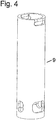
- FIG. 4 shows a perspective view of the upper portion of the guide sleeve 9. According to the guide sleeve has 9 tabs.
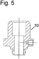
- FIG. 5 shows a perspective view of the intermediate piece 10.
- the tabs of the guide sleeve 9 engage in recesses of the intermediate piece 10, so that a positive connection is formed.
- the seat 6 and the guide sleeve 9 are integrally formed with each other.
- the seat 6, the guide sleeve 9 and the intermediate piece 10 are integrally formed with each other.
Landscapes
- Engineering & Computer Science (AREA)
- General Engineering & Computer Science (AREA)
- Mechanical Engineering (AREA)
- Lift Valve (AREA)
- Magnetically Actuated Valves (AREA)
- Details Of Valves (AREA)
- Motor Or Generator Frames (AREA)
- Seats For Vehicles (AREA)
- Valve Housings (AREA)
Description
- Die Erfindung betrifft eine Armatur mit einem Gehäuse, in dem ein Sitz angeordnet ist, wobei ein Absperrkörper mittels eines Elements zur Einstellung eines Durchflusses verschiebbar angeordnet ist.
- Armaturen werden auch als Absperrorgane oder Stellglieder bezeichnet. Sie dienen zum Sperren und Öffnen von Rohrleitungen bzw. zum Regulieren von Fluidströmen. Ein Absperrkörper gibt mit einer Abhebebewegung einen Strömungsquerschnitt zur Einstellung eines Durchflusses frei. In geschlossener Position verschließt der Absperrkörper den Sitz, der häufig als Sitzring ausgebildet ist. Der Absperrkörper wird mittels eines Elementes verfahren und gibt dann eine meist ringförmige Durchflussöffnung frei. Bei dem Element zur Verschiebung des Absperrkörpers kann beispielsweise ein Ventilschaft oder eine Spindel eingesetzt werden. Der Sitz ist in einem Gehäuse der Armatur angeordnet und ist meist mit einer Dichtung ausgestattet.
- In der
EP 0 177 397 B1 wird ein Ventilhahn beschrieben. Ein Element ist längs der Achse des Hahnes translations-beweglich angeordnet. An einem Ende dieses Elementes befindet sich ein Absperrkörper. Der Ventilsitz wird durch ein ringförmiges Teil gebildet. - In der
EP 1 618 324 B1 wird eine Armatur mit einem Gehäuse beschrieben, die einen hin- und herbeweglichen Absperrkörper umfasst, der in einem Käfig während seiner hin- und hergehenden Bewegungen geführt wird und welcher mit Öffnungen versehen ist. - Die
DE 28 08 094 zeigt ein Ventil mit einem Ventileinsatz, bei dem sich der Sitz auf einfache Weise erneuern lässt. - Die
DE 2 224 269 zeigt ein Druckminderventil mit einem gegen das Ventilgehäuse abgedichteten Einsatzkörper. -
US2014/0264135 A1 zeigt ein Ventil mit einem Einsatzkörper bei dem der Sitz mit einem speziellen Werkzeug einbaubar ist. - Die
GB 2 447 267 A - Die
US 4 493 338 A eine Wechselpatrone für ein Ventil mit einem auswechselbaren Sitz. - Die
DE 85 09 464 U1 zeigt verschieden wirkende Ventileinsätze für ein Heizkörperventil. - Die Öffnungen dienen für das In-Verbindung-Bringen des Einlassdurchgangs mit dem Auslassdurchgang in der geöffneten Position des Absperrkörpers. Die Armatur verfügt über einen Ventilsitz, der vorgesehen ist, um mit dem Absperrkörper in dessen geschlossener Position zusammenzuwirken. Weiterhin weist die Armatur einen Gegensitz mit Auflage auf einem Teil des Gehäuses auf. Eine Dichtung ist zwischen dem Sitz und dem Gegensitz eingeschlossen.
- Bei herkömmlichen Armaturen ist ein Austausch des Ventilsitzes häufig sehr aufwendig. Meist sind dazu Spezialwerkzeuge erforderlich. Auch die Montage des Ventilsitzes ist aufgrund der meist hohen Anzahl an Teilen aufwendig. Zudem besteht die Gefahr von Verwechslungen, sodass bei herkömmlichen Armaturen bei der Montage Fehler auftreten und eine sichere Abdichtung nicht gewährleistet ist.
- Aufgabe der Erfindung ist es, eine Armatur anzugeben, bei der der Sitz auf einfache Weise ausgetauscht werden kann. Zudem soll die Montage des Sitzes erleichtert werden und Verwechselungen vermieden werden. Dabei soll sich die Armatur durch eine preiswerte Herstellungsweise auszeichnen und möglichst wartungsarm sein.
- Diese Aufgabe wird erfindungsgemäß durch eine Armatur mit den Merkmalen des Anspruchs 1 gelöst. Bevorzugte Varianten sind in den Unteransprüchen ausgeführt.
- Erfindungsgemäß ist das Element, welches den Absperrkörper bewegt, zumindest teilweise von einer Führungshülse umgeben. Die Führungshülse weist eine Verbindung mit dem Sitz auf. Vorzugsweise handelt es sich dabei um eine kraftschlüssige Verbindung. Bei einer besonders günstigen Variante handelt es sich dabei um eine Gewindeverbindung.
- Die Führungshülse wird in eine Bohrung im Gehäuse eingefügt und umgibt das stangenartige Element, welches den Absperrkörper bewegt. Die Führungshülse kann aus der Bohrung herausgezogen werden, wobei durch die erfindungsgemäße Verbindung der Führungshülse mit dem Ventilsitz dabei der Ventilsitz ebenfalls aus der Bohrung herausbewegt wird. Bei einem Einführen des Sitzes wird zunächst die Verbindung zwischen der Führungshülse und dem Ventilsitz hergestellt und dann die Führungshülse mitsamt dem Ventilsitz in die Bohrung eingeführt.
- Der Absperrkörper ist zumindest teilweise in der Führungshülse angeordnet. Dabei weist die Führungshülse eine Öffnung für den Durchfluss auf. Wird der Absperrkörper von dem beispielsweise als Spindel ausgeführten Element aus seinem Ventilsitz bewegt, so wird ein Strömungsquerschnitt freigegeben, durch den das Fluid fließt und durch die Öffnung in der Führungshülse zu einem Austrittskanal gelangt. Bei einer vorteilhaften Variante der Erfindung steht die Führungshülse mit einem Zwischenstück in Verbindung. Das Zwischenstück ist zumindest teilweise außerhalb des Gehäuses angeordnet. Vorzugsweise ragt es dabei mit einem Abschnitt in die Bohrung des Gehäuses hinein, in der die Führungshülse angeordnet ist. Vorzugsweise besteht zwischen der Führungshülse und dem Zwischenstück eine formschlüssige Verbindung. Dazu kann das Zwischenstück Vertiefungen aufweisen, in die die Führungshülse teilweise eingreift. Dies kann durch das Verpressen von Stegen im Bauteil realisiert werden. Die erfindungsgemäße Verbindung der Führungshülse mit dem Zwischenstück ermöglicht das Einsetzen eines Dichtelementes. Zudem kann man durch Ziehen an dem Zwischenstück den kompletten Strang aus dem Gehäuse entfernen. Die formschlüssige Verbindung der Führungshülse mit dem Zwischenstück gewährleistet zudem eine Verdrehsicherung. Die Laschen im Führungsrohr, welche in Vertiefungen des Zwischenstücks eingreifen, gewährleisten die Verdrehsicherung. Dabei ist ein Einbau vorzugsweise nur in einer Orientierung möglich. Es handelt sich somit um eine formschlüssige Verbindung, die erfindungsgemäß ohne weitere Bauteile auskommt und eine Verdrehsicherung gewährleistet.
- Erfindungsgemäß ist am Sitz ein Dichtelement angeordnet, das eine Verbindung mit dem Sitz aufweist. Erfindungsgemäß handelt es sich dabei um eine formschlüssige Verbindung. Dies wird durch eine Hinterschneidung realisiert. Eine solche Hinterschneidung ermöglicht auch das sichere Herausziehen des Dichtelements. Im unverpressten Zustand hat die Dichtung einen Rechteckquerschnitt, und die Dichtung füllt die Hinterschneidung nicht aus. Erst durch ein Verpressen über den Sitz wird die Dichtung zu einer Formänderung geführt. Beim Anbringen der Dichtung wird diese auf den Ventilsitz geschoben. Dadurch kann das Dichtelement ohne zusätzliche Teile eingesetzt werden. Die Dichtung wird in eine Hinterdrehung gepresst. Dabei sind auch andere Geometrien der Hinterdrehung denkbar. Erfindungsgemäß ist ein Ausbau ohne zusätzliche Teile möglich. Die Scherkraft des Dichtelements ist dabei ausreichend.
- Erfindungsgemäß weist der Sitz eine Aussparung für das Dichtelement auf. Bei herkömmlichen Armaturen gemäß dem Stand der Technik ist die Dichtung gekammert. Bei der erfindungsgemäßen Armatur ist kein weiteres Element um die Dichtung herum erforderlich. Dies bringt Fertigungstechnisch erhebliche Vorteile mit sich.
- Weitere Merkmale und Vorteile der Erfindung ergeben sich aus der Beschreibung eines Ausführungsbeispiels anhand von Zeichnungen und aus den Zeichnungen selbst.
- Dabei zeigt:
- Figur 1
- eine Schnittzeichnung durch einen Teil der Armatur,
- Figur 2
- eine Ausschnittsvergrößerung eines Bereichs des Ventilsitzes,
- Figur 3
- eine Ausschnittsvergrößerung eines Bereichs der Führungshülse beim Zusammenwirken mit dem Zwischenstück,
- Figur 4
- eine perspektivische Darstellung der Führungshülse,
- Figur 5
- eine perspektivische Darstellung des Zwischenstücks.
-
Figur 1 zeigt einen Ausschnitt einer Schnittdarstellung einer Armatur, die ein Gehäuse 1 aufweist. Das Fluid strömt durch eine Zuströmpassage 2. Ein Absperrkörper 3 wird durch eine Translationsbewegung verschoben und gibt einen Strömungsquerschnitt frei, durch den das Fluid strömt und zu einer Ausströmpassage gelangt. Im Ausführungsbeispiel ist der Absperrkörper 3 zylinderförmig ausgebildet. - Die Translationsbewegung des Absperrkörpers 3 erfolgt mittels eines stangenartigen Elements 5, das im Ausführungsbeispiel als Spindel ausgestaltet ist. Das Element 5 steht mit einem in
Figur 1 nicht dargestellten Stellantrieb in Verbindung, welcher das Element 5 in vertikaler Richtung nach oben oder unten bewegt. Alternativ kann auch ein Handrad zur Betätigung zum Einsatz kommen. Im Ausführungsbeispiel weist der Absperrkörper 3 eine Öffnung auf, in die das Element 5 eingreift, wobei eine kraftschlüssige Verbindung zwischen dem Absperrkörper 3 und dem Element 5 besteht. Alternativ zur dargestellten Variante kann der Absperrkörper 3 auch an dem Element 5 angeformt sein, sodass der Absperrkörper 3 und das Element 5 einstückig ausgebildet sind. - In dem Gehäuse 1 ist ein Sitz 6 angeordnet. Der Sitz 6 ist ringförmig ausgebildet und wirkt mit dem Absperrkörper 3 in dessen geschlossener Position zusammen. Zwischen dem ringförmigen Sitz 6 und dem Gehäuse 1 ist ein Dichtelement 7 angeordnet. Das Dichtelement 7 ist ringförmig ausgebildet. Ein Dichtelement 8 sorgt für die Abdichtung zwischen dem Absperrkörper 3 und dem Sitz 6 in geschlossener Position.
- Das Element 5, welches den Absperrkörper 3 bewegt, ist von einer Führungshülse 9 umgeben. Die Führungshülse 9 dient als Abstandshülse und steht mit einem Zwischenstück 10 in Verbindung. Ein Dichtelement 11 dichtet das Gehäuse 1 zum Zwischenstück 10 ab.
- Das Zwischenstück 10 weist eine innere Öffnung auf, in der das Element 5 verschieblich angeordnet ist. Das Zwischenstück 10 greift in eine Öffnung eines Bauteils 12 ein, das im Ausführungsbeispiel als Bügel ausgebildet ist. Das Zwischenstück 10 ist in seinem oberen Bereich von einer Mutter 13 umgeben. Zwischen der Mutter 13 und dem als Bügel ausgebildeten Bauteil 12 ist eine Scheibe 14 angeordnet.
- Oberhalb der Mutter 13 ist eine Schraube 15 angeordnet.
-
Figur 2 zeigt eine Ausschnittsvergrößerung eines Bereichs des Ventilsitzes. Erfindungsgemäß erstreckt sich die Führungshülse 9 bis zum Sitz 6 und weist mit dem ringförmigen Sitz 6 eine Verbindung auf. Dazu ist die Führungshülse 9 in ihrem unteren Bereich mit einem Innengewinde versehen, das in ein Außengewinde des ringförmigen Sitzes 6 eingreift. - Der ringförmige Sitz 6 weist einen Vorsprung 16 auf. Der Vorsprung 16 erstreckt sich entlang des Umfanges des Sitzes 6. Weiterhin weist der ringförmige Sitz 6 eine Aussparung 17 auf, die sich als Nut entlang des Umfanges des ringförmigen Sitzes 6 erstreckt. Durch diese Gestaltung entsteht eine formschlüssige Verbindung des Sitzes 6 mit dem Dichtelement 7, welches durch die Hinterschneidung realisiert wird.
- Beim Anbringen des Dichtelements 7 wird das Dichtelement 7 auf den ringförmigen Sitz 6 geschoben. Erfindungsgemäß kann das Dichtelement 7 ohne zusätzliche Teile eingesetzt werden. Über die Schraube 15 wird das Dichtelement 7 in die Hinterdrehung gepresst. Andere Geometrien der Hinterdrehung sind denkbar. Die erfindungsgemäße Konstruktion ermöglicht einen Ausbau ohne zusätzliche Teile. Die Scherkraft des Dichtelements 7 ist hierfür ausreichend. Im unverpressten Zustand hat das Dichtelement 7 einen Rechteckquerschnitt und füllt die Hinterschneidung nicht aus. Erst das Verpressen über den Sitz 6 zwingt das Dichtelement 7 zu einer Formänderung.
-
Figur 3 zeigt einen vergrößerten Ausschnitt des oberen Bereichs der Führungshülse 9. Erfindungsgemäß weist die Führungshülse 9 eine Verbindung mit dem Zwischenstück 10 auf. Dabei handelt es sich um eine formschlüssige Verbindung. Im Ausführungsbeispiel sind Laschen in der Führungshülse 9 realisiert, die in Vertiefungen des Zwischenstücks 10 gepresst werden. Das Zwischenstück 10 weist dazu eine Aussparung 18 auf, die als Nut ringförmig entlang des Umfanges des Zwischenstücks 10 verläuft. Weiterhin weist das Zwischenstück 10 einen Vorsprung 19 auf, der ringförmig entlang des Umfanges verläuft. - Die formschlüssige Verbindung zwischen der Führungshülse 9 und dem Zwischenstück 10 wird durch Verpressen von Stegen realisiert. In Kombination mit der kraftschlüssigen Verbindung der Führungshülse 9 mit dem Sitz 6 und der formschlüssigen Verbindung des Sitzes 6 mit dem Dichtelement 7 kann durch ein Ziehen an dem Zwischenstück 10 der komplette Strang aus dem Gehäuse 1 herausgezogen werden.
- Das Verdrehen des Wechselsystems wird über die formschlüssige Verbindung der Führungshülse 9 mit dem Zwischenstück 10 realisiert. Der Einbau ist nur in einer Orientierung möglich. Der Tausch des Wechselsitzsystems ist in kürzester Zeit ohne Zuhilfenahme von Spezialwerkzeugen möglich. Im Gegensatz zu herkömmlichen Systemen werden dabei Teile eingespannt und die Montage ist einfacher und zudem verwechslungssicher gestaltet.
- Die Verbindung der Führungshülse 9 mit dem Zwischenstück 10 ermöglicht das Einsetzen des Dichtelements 7 sowie das Herausziehen des Dichtelements 7. Die Verbindung ist verdrehsicher ausgeführt.
-
Figur 4 zeigt eine perspektivische Darstellung des oberen Bereichs der Führungshülse 9. Erfindungsgemäß weist die Führungshülse 9 Laschen auf. -
Figur 5 zeigt eine perspektivische Darstellung des Zwischenstücks 10. Die Laschen der Führungshülse 9 greifen in Vertiefungen des Zwischenstücks 10 ein, sodass eine formschlüssige Verbindung entsteht. - Bei einer nicht dargestellten alternativen Variante der Erfindung sind der Sitz 6 und die Führungshülse 9 einstückig miteinander ausgebildet.
- Bei einer weiteren nicht dargestellten Variante sind der Sitz 6, die Führungshülse 9 und das Zwischenstück 10 einstückig miteinander ausgebildet.
Claims (8)
- Armatur mit einem Gehäuse (1), in dem ein Sitz (6) angeordnet ist, wobei ein Absperrkörper (3) mittels eines Elements (5) zur Einstellung eines Durchflusses verschiebbar angeordnet ist, wobei das Element (5) zumindest teilweise von einer Führungshülse (9) umgeben ist, die eine Verbindung mit dem Sitz (6) aufweist, wobei der Sitz (6) eine Aussparung (17) für ein Dichtelement (7) aufweist, wobei am Sitz (6) das Dichtelement (7) angeordnet ist, das eine formschlüssige Verbindung mit dem Sitz (6) aufweist, wobei diese durch eine Hinterschneidung realisiert ist, wobei die Hinterschneidung das Herausziehen des Dichtelements ermöglicht,
dadurch gekennzeichnet, dass
im unverpressten Zustand das Dichtelement (7) einen Rechteckquerschnitt hat und die Hinterschneidung nicht ausfüllt, und dass das Dichtelement (7) erst durch ein Verpressen über den Sitz (6) zu einer Formänderung geführt wird und in die Hinterschneidung gepresst wird. - Armatur nach Anspruch 1, dadurch gekennzeichnet, dass die Führungshülse (9) eine kraftschlüssige Verbindung mit dem Sitz (6) aufweist, insbesondere eine Gewindeverbindung.
- Armatur nach Anspruch 1 oder 2, dadurch gekennzeichnet, dass der Absperrkörper (3) zumindest teilweise in der Führungshülse (9) angeordnet ist.
- Armatur nach einem der Ansprüche 1 bis 3, dadurch gekennzeichnet, dass die Führungshülse (9) mit einem Zwischenstück (10) in Verbindung steht.
- Armatur nach Anspruch 4, dadurch gekennzeichnet, dass das Zwischenstück (10) zumindest teilweise außerhalb des Gehäuses (1) angeordnet ist.
- Armatur nach Anspruch 4 oder 5, dadurch gekennzeichnet, dass die Führungshülse (9) eine formschlüssige Verbindung mit dem Zwischenstück (10) aufweist.
- Armatur nach Anspruch 6, dadurch gekennzeichnet, dass das Zwischenstück (10) Vertiefungen aufweist, in die die Führungshülse (9) eingreift.
- Armatur nach einem der Ansprüche 1 bis 7, dadurch gekennzeichnet, dass die Führungshülse (9) mindestens eine Öffnung für den Durchfluss aufweist.
Priority Applications (1)
| Application Number | Priority Date | Filing Date | Title |
|---|---|---|---|
| SI201530885T SI3207293T1 (sl) | 2014-10-13 | 2015-10-07 | Armatura s sistemom nadomestljivega sedeža |
Applications Claiming Priority (2)
| Application Number | Priority Date | Filing Date | Title |
|---|---|---|---|
| DE102014220675.8A DE102014220675B4 (de) | 2014-10-13 | 2014-10-13 | Armatur mit Wechselsitzsystem |
| PCT/EP2015/073100 WO2016058874A1 (de) | 2014-10-13 | 2015-10-07 | Armatur mit wechselsitzsystem |
Publications (2)
| Publication Number | Publication Date |
|---|---|
| EP3207293A1 EP3207293A1 (de) | 2017-08-23 |
| EP3207293B1 true EP3207293B1 (de) | 2019-06-05 |
Family
ID=54330736
Family Applications (1)
| Application Number | Title | Priority Date | Filing Date |
|---|---|---|---|
| EP15781607.5A Revoked EP3207293B1 (de) | 2014-10-13 | 2015-10-07 | Armatur mit wechselsitzsystem |
Country Status (13)
| Country | Link |
|---|---|
| US (1) | US10428958B2 (de) |
| EP (1) | EP3207293B1 (de) |
| JP (1) | JP6677721B2 (de) |
| KR (1) | KR102132364B1 (de) |
| CN (1) | CN106795971B (de) |
| BR (1) | BR112017007490B1 (de) |
| CA (1) | CA2964277C (de) |
| DE (1) | DE102014220675B4 (de) |
| ES (1) | ES2740774T3 (de) |
| RU (1) | RU2699597C2 (de) |
| SI (1) | SI3207293T1 (de) |
| WO (1) | WO2016058874A1 (de) |
| ZA (1) | ZA201701942B (de) |
Families Citing this family (5)
| Publication number | Priority date | Publication date | Assignee | Title |
|---|---|---|---|---|
| DE102019104589A1 (de) * | 2019-02-22 | 2020-08-27 | Samson Ag | Ventilsitz-Käfiganordnung |
| US11041573B2 (en) * | 2019-05-08 | 2021-06-22 | Fisher Controls International Llc | Control valves including valve trim having relative movement between the bonnet and the cage |
| CN110274037A (zh) * | 2019-05-29 | 2019-09-24 | 黑龙江北方阀业有限责任公司 | 一种连续排污阀 |
| US11407070B2 (en) * | 2020-12-14 | 2022-08-09 | Fisher Controls International Llc | Bonnet and valve trim assembly and related methods |
| US11891121B2 (en) * | 2021-07-13 | 2024-02-06 | Honda Motor Co., Ltd. | Wheel casing |
Family Cites Families (23)
| Publication number | Priority date | Publication date | Assignee | Title |
|---|---|---|---|---|
| US3813079A (en) | 1971-12-10 | 1974-05-28 | Masoneilan Int Inc | Quick change apparatus for effecting gas flow pressure reduction with low noise generator |
| US4137934A (en) * | 1977-02-25 | 1979-02-06 | Fisher Controls Company | Valve construction |
| CA1182795A (en) * | 1982-01-27 | 1985-02-19 | Sigurdur G. Petursson | Washerless faucet |
| FR2570790B1 (fr) | 1984-09-26 | 1987-03-20 | Sereg Soc | Robinet a soupape a siege demontable et a maintenance rapide |
| DE8509464U1 (de) | 1985-03-29 | 1986-07-31 | F.W. Oventrop Arn. Sohn Kg, 5787 Olsberg | Thermostatisch gesteuertes Heizkörperventil mit unterschiedlichen Ventileinsätzen |
| US5255704A (en) | 1993-01-27 | 1993-10-26 | Technical Products & Precision Manufacturing Co. | Leakproof hydraulic valve |
| LU88384A1 (de) * | 1993-07-16 | 1995-02-01 | Hydrolux Sarl | 2-Wege-Einbauventil als Sitzventil |
| CN2222834Y (zh) * | 1995-03-15 | 1996-03-20 | 林文政 | 截止阀 |
| CN1410692A (zh) * | 2001-09-28 | 2003-04-16 | 左学禹 | 新结构陶瓷阀门 |
| FR2853947B1 (fr) | 2003-04-18 | 2006-02-10 | Velan S A S | Dispositif a clapet de regulation du debit d'un fluide |
| EP1898006B1 (de) * | 2006-09-08 | 2016-03-09 | R. Nussbaum AG | Frostsichere Auslaufarmatur |
| GB2447267A (en) | 2007-03-05 | 2008-09-10 | Ltd Dynamic Controls | Fluid flow valve |
| RU2360169C1 (ru) * | 2007-11-26 | 2009-06-27 | Закрытое акционерное общество "Научно-производственная фирма "Центральное конструкторское бюро арматуростроения" | Уплотнительный узел затвора клапана |
| RU2374540C1 (ru) * | 2008-04-22 | 2009-11-27 | Валерий Борисович Овандер | Шаровой кран системы овандер |
| TWI377307B (en) * | 2009-03-26 | 2012-11-21 | Smc Kk | Flow rate control valve and assembly method therefor |
| KR101930081B1 (ko) * | 2010-05-07 | 2018-12-17 | 에스피엑스 플로우 인크 | 볼 밸브 시트 씰 |
| US8574513B2 (en) * | 2011-04-20 | 2013-11-05 | California Institute Of Technology | Single-layer PCB microfluidics |
| DE102012100433A1 (de) | 2012-01-19 | 2013-07-25 | Caradon Stelrad B.V. | Ventileinsatzelement |
| DE102012223608A1 (de) | 2012-12-18 | 2014-06-18 | Caradon Stelrad B.V. | Ventileinsatzelement sowie Verfahren zur Ausbildung einer Nut an einem Gehäuse eines Ventileinsatzelements |
| US8783653B2 (en) * | 2012-12-21 | 2014-07-22 | Mac Valves, Inc. | Multi-port modular valve with snap-in seat |
| US9297469B2 (en) * | 2013-03-14 | 2016-03-29 | Fisher Controls International Llc | Valve seat assemblies |
| US9267604B2 (en) * | 2013-03-14 | 2016-02-23 | Fisher Controls International Llc | Valve seat apparatus for use with fluid valves |
| CN203453501U (zh) | 2013-09-18 | 2014-02-26 | 北京星光沃特传动研究所 | 一种软硬双阀口截止阀 |
-
2014
- 2014-10-13 DE DE102014220675.8A patent/DE102014220675B4/de active Active
-
2015
- 2015-10-07 WO PCT/EP2015/073100 patent/WO2016058874A1/de not_active Ceased
- 2015-10-07 JP JP2017519511A patent/JP6677721B2/ja active Active
- 2015-10-07 CA CA2964277A patent/CA2964277C/en active Active
- 2015-10-07 BR BR112017007490-7A patent/BR112017007490B1/pt active IP Right Grant
- 2015-10-07 RU RU2017116706A patent/RU2699597C2/ru active
- 2015-10-07 SI SI201530885T patent/SI3207293T1/sl unknown
- 2015-10-07 EP EP15781607.5A patent/EP3207293B1/de not_active Revoked
- 2015-10-07 CN CN201580055385.4A patent/CN106795971B/zh active Active
- 2015-10-07 KR KR1020177012967A patent/KR102132364B1/ko not_active Expired - Fee Related
- 2015-10-07 US US15/516,903 patent/US10428958B2/en active Active
- 2015-10-07 ES ES15781607T patent/ES2740774T3/es active Active
-
2017
- 2017-03-20 ZA ZA2017/01942A patent/ZA201701942B/en unknown
Non-Patent Citations (1)
| Title |
|---|
| None * |
Also Published As
| Publication number | Publication date |
|---|---|
| WO2016058874A1 (de) | 2016-04-21 |
| BR112017007490A8 (pt) | 2018-07-31 |
| RU2017116706A3 (de) | 2019-05-22 |
| JP2017534815A (ja) | 2017-11-24 |
| BR112017007490A2 (pt) | 2018-02-14 |
| RU2017116706A (ru) | 2018-11-15 |
| ES2740774T3 (es) | 2020-02-06 |
| BR112017007490B1 (pt) | 2022-03-03 |
| ZA201701942B (en) | 2022-05-25 |
| CN106795971B (zh) | 2020-09-22 |
| EP3207293A1 (de) | 2017-08-23 |
| CA2964277A1 (en) | 2016-04-21 |
| JP6677721B2 (ja) | 2020-04-08 |
| SI3207293T1 (sl) | 2019-10-30 |
| US20170299066A1 (en) | 2017-10-19 |
| US10428958B2 (en) | 2019-10-01 |
| KR102132364B1 (ko) | 2020-07-10 |
| CA2964277C (en) | 2022-12-13 |
| RU2699597C2 (ru) | 2019-09-06 |
| DE102014220675A1 (de) | 2016-04-14 |
| DE102014220675B4 (de) | 2025-11-13 |
| CN106795971A (zh) | 2017-05-31 |
| KR20170066649A (ko) | 2017-06-14 |
Similar Documents
| Publication | Publication Date | Title |
|---|---|---|
| EP3207293B1 (de) | Armatur mit wechselsitzsystem | |
| DE3100037C2 (de) | ||
| EP3479008A1 (de) | Tankventil | |
| EP3004702B1 (de) | Kombination aus einem gehäuse und einem ventil | |
| EP2252820A1 (de) | Siebfilter und einbauventil mit siebfilter | |
| EP2249072B1 (de) | Anschlussvorrichtung für ein Kunstoffrohr an einem Anschlussnippel | |
| DE3923579C2 (de) | Anschlußarmatur für Rohre, insbesondere für Kunststoffrohre | |
| WO2015135675A1 (de) | Sanitärarmatur | |
| EP3660620A1 (de) | Druckreduzierventil | |
| DE102008010347A1 (de) | Verteilerventil mit integrierter Durchflussmesseinrichtung | |
| DE102017218140A1 (de) | Drucksystemkomponente, Werkzeug zur Demontage einer Drucksystemkomponente, Drucksystem mit einer Drucksystemkomponente und Verfahren zur Demontage einer Drucksystemkomponente | |
| EP3024708B1 (de) | Hauptbremszylinderanordnung einer kraftfahrzeugbremsanlage mit filterelement sowie fluidreservoir und einsatzelement hierfür | |
| AT404064B (de) | Armatur zum anschluss eines heizkörpers an die zulauf- und rücklaufrohrleitungen einer zweirohrheizanlage | |
| EP2113698A2 (de) | Sitzventil | |
| DE102012018731A1 (de) | Sicherheitsabsperrvorrichtung und Verfahren zu seiner Herstellung | |
| WO2018083255A1 (de) | Absperrventil | |
| EP2726678A1 (de) | Ventileinheit zur belüftungs- oder rückstromsteuerung | |
| DE102012102501A1 (de) | Fluiddichte Leitungsdurchführung | |
| DE2500552C2 (de) | Sicherungsventil fuer rohr- bzw. schlauchbrueche | |
| DE202007005224U1 (de) | Magnetventil | |
| EP0336397B1 (de) | Wasserzähler-Anschlusselement | |
| DE102006008678B4 (de) | Ventil, insbesondere Heizkörperventil und Einsatz für ein derartiges Ventil | |
| EP2775178B1 (de) | Mehrwegeventilblock | |
| EP2525121B1 (de) | Ventileinsatzelement | |
| DE102009061109B3 (de) | Koaxialventil mit Dichtelement |
Legal Events
| Date | Code | Title | Description |
|---|---|---|---|
| STAA | Information on the status of an ep patent application or granted ep patent |
Free format text: STATUS: THE INTERNATIONAL PUBLICATION HAS BEEN MADE |
|
| PUAI | Public reference made under article 153(3) epc to a published international application that has entered the european phase |
Free format text: ORIGINAL CODE: 0009012 |
|
| STAA | Information on the status of an ep patent application or granted ep patent |
Free format text: STATUS: REQUEST FOR EXAMINATION WAS MADE |
|
| 17P | Request for examination filed |
Effective date: 20170327 |
|
| AK | Designated contracting states |
Kind code of ref document: A1 Designated state(s): AL AT BE BG CH CY CZ DE DK EE ES FI FR GB GR HR HU IE IS IT LI LT LU LV MC MK MT NL NO PL PT RO RS SE SI SK SM TR |
|
| AX | Request for extension of the european patent |
Extension state: BA ME |
|
| DAV | Request for validation of the european patent (deleted) | ||
| DAX | Request for extension of the european patent (deleted) | ||
| RAP1 | Party data changed (applicant data changed or rights of an application transferred) |
Owner name: KSB SE & CO. KGAA |
|
| STAA | Information on the status of an ep patent application or granted ep patent |
Free format text: STATUS: EXAMINATION IS IN PROGRESS |
|
| 17Q | First examination report despatched |
Effective date: 20180702 |
|
| GRAP | Despatch of communication of intention to grant a patent |
Free format text: ORIGINAL CODE: EPIDOSNIGR1 |
|
| STAA | Information on the status of an ep patent application or granted ep patent |
Free format text: STATUS: GRANT OF PATENT IS INTENDED |
|
| INTG | Intention to grant announced |
Effective date: 20190226 |
|
| GRAS | Grant fee paid |
Free format text: ORIGINAL CODE: EPIDOSNIGR3 |
|
| GRAA | (expected) grant |
Free format text: ORIGINAL CODE: 0009210 |
|
| STAA | Information on the status of an ep patent application or granted ep patent |
Free format text: STATUS: THE PATENT HAS BEEN GRANTED |
|
| AK | Designated contracting states |
Kind code of ref document: B1 Designated state(s): AL AT BE BG CH CY CZ DE DK EE ES FI FR GB GR HR HU IE IS IT LI LT LU LV MC MK MT NL NO PL PT RO RS SE SI SK SM TR |
|
| REG | Reference to a national code |
Ref country code: GB Ref legal event code: FG4D Free format text: NOT ENGLISH |
|
| REG | Reference to a national code |
Ref country code: CH Ref legal event code: EP |
|
| REG | Reference to a national code |
Ref country code: AT Ref legal event code: REF Ref document number: 1140337 Country of ref document: AT Kind code of ref document: T Effective date: 20190615 |
|
| REG | Reference to a national code |
Ref country code: IE Ref legal event code: FG4D Free format text: LANGUAGE OF EP DOCUMENT: GERMAN |
|
| REG | Reference to a national code |
Ref country code: DE Ref legal event code: R096 Ref document number: 502015009250 Country of ref document: DE |
|
| REG | Reference to a national code |
Ref country code: NL Ref legal event code: FP |
|
| REG | Reference to a national code |
Ref country code: SE Ref legal event code: TRGR |
|
| REG | Reference to a national code |
Ref country code: LT Ref legal event code: MG4D |
|
| PG25 | Lapsed in a contracting state [announced via postgrant information from national office to epo] |
Ref country code: AL Free format text: LAPSE BECAUSE OF FAILURE TO SUBMIT A TRANSLATION OF THE DESCRIPTION OR TO PAY THE FEE WITHIN THE PRESCRIBED TIME-LIMIT Effective date: 20190605 Ref country code: NO Free format text: LAPSE BECAUSE OF FAILURE TO SUBMIT A TRANSLATION OF THE DESCRIPTION OR TO PAY THE FEE WITHIN THE PRESCRIBED TIME-LIMIT Effective date: 20190905 Ref country code: HR Free format text: LAPSE BECAUSE OF FAILURE TO SUBMIT A TRANSLATION OF THE DESCRIPTION OR TO PAY THE FEE WITHIN THE PRESCRIBED TIME-LIMIT Effective date: 20190605 Ref country code: LT Free format text: LAPSE BECAUSE OF FAILURE TO SUBMIT A TRANSLATION OF THE DESCRIPTION OR TO PAY THE FEE WITHIN THE PRESCRIBED TIME-LIMIT Effective date: 20190605 |
|
| PG25 | Lapsed in a contracting state [announced via postgrant information from national office to epo] |
Ref country code: RS Free format text: LAPSE BECAUSE OF FAILURE TO SUBMIT A TRANSLATION OF THE DESCRIPTION OR TO PAY THE FEE WITHIN THE PRESCRIBED TIME-LIMIT Effective date: 20190605 Ref country code: BG Free format text: LAPSE BECAUSE OF FAILURE TO SUBMIT A TRANSLATION OF THE DESCRIPTION OR TO PAY THE FEE WITHIN THE PRESCRIBED TIME-LIMIT Effective date: 20190905 Ref country code: GR Free format text: LAPSE BECAUSE OF FAILURE TO SUBMIT A TRANSLATION OF THE DESCRIPTION OR TO PAY THE FEE WITHIN THE PRESCRIBED TIME-LIMIT Effective date: 20190906 Ref country code: LV Free format text: LAPSE BECAUSE OF FAILURE TO SUBMIT A TRANSLATION OF THE DESCRIPTION OR TO PAY THE FEE WITHIN THE PRESCRIBED TIME-LIMIT Effective date: 20190605 |
|
| PG25 | Lapsed in a contracting state [announced via postgrant information from national office to epo] |
Ref country code: PT Free format text: LAPSE BECAUSE OF FAILURE TO SUBMIT A TRANSLATION OF THE DESCRIPTION OR TO PAY THE FEE WITHIN THE PRESCRIBED TIME-LIMIT Effective date: 20191007 Ref country code: CZ Free format text: LAPSE BECAUSE OF FAILURE TO SUBMIT A TRANSLATION OF THE DESCRIPTION OR TO PAY THE FEE WITHIN THE PRESCRIBED TIME-LIMIT Effective date: 20190605 Ref country code: RO Free format text: LAPSE BECAUSE OF FAILURE TO SUBMIT A TRANSLATION OF THE DESCRIPTION OR TO PAY THE FEE WITHIN THE PRESCRIBED TIME-LIMIT Effective date: 20190605 Ref country code: EE Free format text: LAPSE BECAUSE OF FAILURE TO SUBMIT A TRANSLATION OF THE DESCRIPTION OR TO PAY THE FEE WITHIN THE PRESCRIBED TIME-LIMIT Effective date: 20190605 Ref country code: SK Free format text: LAPSE BECAUSE OF FAILURE TO SUBMIT A TRANSLATION OF THE DESCRIPTION OR TO PAY THE FEE WITHIN THE PRESCRIBED TIME-LIMIT Effective date: 20190605 |
|
| REG | Reference to a national code |
Ref country code: ES Ref legal event code: FG2A Ref document number: 2740774 Country of ref document: ES Kind code of ref document: T3 Effective date: 20200206 |
|
| REG | Reference to a national code |
Ref country code: DE Ref legal event code: R026 Ref document number: 502015009250 Country of ref document: DE |
|
| PG25 | Lapsed in a contracting state [announced via postgrant information from national office to epo] |
Ref country code: IS Free format text: LAPSE BECAUSE OF FAILURE TO SUBMIT A TRANSLATION OF THE DESCRIPTION OR TO PAY THE FEE WITHIN THE PRESCRIBED TIME-LIMIT Effective date: 20191005 Ref country code: IT Free format text: LAPSE BECAUSE OF FAILURE TO SUBMIT A TRANSLATION OF THE DESCRIPTION OR TO PAY THE FEE WITHIN THE PRESCRIBED TIME-LIMIT Effective date: 20190605 Ref country code: SM Free format text: LAPSE BECAUSE OF FAILURE TO SUBMIT A TRANSLATION OF THE DESCRIPTION OR TO PAY THE FEE WITHIN THE PRESCRIBED TIME-LIMIT Effective date: 20190605 |
|
| PLBI | Opposition filed |
Free format text: ORIGINAL CODE: 0009260 |
|
| PLAX | Notice of opposition and request to file observation + time limit sent |
Free format text: ORIGINAL CODE: EPIDOSNOBS2 |
|
| PG25 | Lapsed in a contracting state [announced via postgrant information from national office to epo] |
Ref country code: TR Free format text: LAPSE BECAUSE OF FAILURE TO SUBMIT A TRANSLATION OF THE DESCRIPTION OR TO PAY THE FEE WITHIN THE PRESCRIBED TIME-LIMIT Effective date: 20190605 |
|
| 26 | Opposition filed |
Opponent name: VELAN S.A.S. Effective date: 20200227 |
|
| REG | Reference to a national code |
Ref country code: FI Ref legal event code: MDE Opponent name: VELAN S.A.S. |
|
| PG25 | Lapsed in a contracting state [announced via postgrant information from national office to epo] |
Ref country code: PL Free format text: LAPSE BECAUSE OF FAILURE TO SUBMIT A TRANSLATION OF THE DESCRIPTION OR TO PAY THE FEE WITHIN THE PRESCRIBED TIME-LIMIT Effective date: 20190605 Ref country code: DK Free format text: LAPSE BECAUSE OF FAILURE TO SUBMIT A TRANSLATION OF THE DESCRIPTION OR TO PAY THE FEE WITHIN THE PRESCRIBED TIME-LIMIT Effective date: 20190605 |
|
| PG25 | Lapsed in a contracting state [announced via postgrant information from national office to epo] |
Ref country code: MC Free format text: LAPSE BECAUSE OF FAILURE TO SUBMIT A TRANSLATION OF THE DESCRIPTION OR TO PAY THE FEE WITHIN THE PRESCRIBED TIME-LIMIT Effective date: 20190605 |
|
| PLBB | Reply of patent proprietor to notice(s) of opposition received |
Free format text: ORIGINAL CODE: EPIDOSNOBS3 |
|
| PG25 | Lapsed in a contracting state [announced via postgrant information from national office to epo] |
Ref country code: LU Free format text: LAPSE BECAUSE OF NON-PAYMENT OF DUE FEES Effective date: 20191007 |
|
| PG25 | Lapsed in a contracting state [announced via postgrant information from national office to epo] |
Ref country code: IE Free format text: LAPSE BECAUSE OF NON-PAYMENT OF DUE FEES Effective date: 20191007 |
|
| PG25 | Lapsed in a contracting state [announced via postgrant information from national office to epo] |
Ref country code: CY Free format text: LAPSE BECAUSE OF FAILURE TO SUBMIT A TRANSLATION OF THE DESCRIPTION OR TO PAY THE FEE WITHIN THE PRESCRIBED TIME-LIMIT Effective date: 20190605 |
|
| PG25 | Lapsed in a contracting state [announced via postgrant information from national office to epo] |
Ref country code: HU Free format text: LAPSE BECAUSE OF FAILURE TO SUBMIT A TRANSLATION OF THE DESCRIPTION OR TO PAY THE FEE WITHIN THE PRESCRIBED TIME-LIMIT; INVALID AB INITIO Effective date: 20151007 Ref country code: MT Free format text: LAPSE BECAUSE OF FAILURE TO SUBMIT A TRANSLATION OF THE DESCRIPTION OR TO PAY THE FEE WITHIN THE PRESCRIBED TIME-LIMIT Effective date: 20190605 |
|
| REG | Reference to a national code |
Ref country code: AT Ref legal event code: MM01 Ref document number: 1140337 Country of ref document: AT Kind code of ref document: T Effective date: 20201007 |
|
| PG25 | Lapsed in a contracting state [announced via postgrant information from national office to epo] |
Ref country code: AT Free format text: LAPSE BECAUSE OF NON-PAYMENT OF DUE FEES Effective date: 20201007 |
|
| PG25 | Lapsed in a contracting state [announced via postgrant information from national office to epo] |
Ref country code: MK Free format text: LAPSE BECAUSE OF FAILURE TO SUBMIT A TRANSLATION OF THE DESCRIPTION OR TO PAY THE FEE WITHIN THE PRESCRIBED TIME-LIMIT Effective date: 20190605 |
|
| REG | Reference to a national code |
Ref country code: DE Ref legal event code: R103 Ref document number: 502015009250 Country of ref document: DE Ref country code: DE Ref legal event code: R064 Ref document number: 502015009250 Country of ref document: DE |
|
| RDAF | Communication despatched that patent is revoked |
Free format text: ORIGINAL CODE: EPIDOSNREV1 |
|
| PGFP | Annual fee paid to national office [announced via postgrant information from national office to epo] |
Ref country code: NL Payment date: 20221021 Year of fee payment: 8 Ref country code: FR Payment date: 20221021 Year of fee payment: 8 |
|
| PGFP | Annual fee paid to national office [announced via postgrant information from national office to epo] |
Ref country code: SE Payment date: 20221021 Year of fee payment: 8 Ref country code: GB Payment date: 20221019 Year of fee payment: 8 Ref country code: FI Payment date: 20221020 Year of fee payment: 8 Ref country code: ES Payment date: 20221102 Year of fee payment: 8 Ref country code: DE Payment date: 20221117 Year of fee payment: 8 |
|
| PGFP | Annual fee paid to national office [announced via postgrant information from national office to epo] |
Ref country code: SI Payment date: 20220926 Year of fee payment: 8 Ref country code: CH Payment date: 20221026 Year of fee payment: 8 Ref country code: BE Payment date: 20221021 Year of fee payment: 8 |
|
| RDAG | Patent revoked |
Free format text: ORIGINAL CODE: 0009271 |
|
| STAA | Information on the status of an ep patent application or granted ep patent |
Free format text: STATUS: PATENT REVOKED |
|
| REG | Reference to a national code |
Ref country code: CH Ref legal event code: PL |
|
| 27W | Patent revoked |
Effective date: 20220831 |
|
| GBPR | Gb: patent revoked under art. 102 of the ep convention designating the uk as contracting state |
Effective date: 20220831 |
|
| REG | Reference to a national code |
Ref country code: AT Ref legal event code: MA03 Ref document number: 1140337 Country of ref document: AT Kind code of ref document: T Effective date: 20220831 |
|
| REG | Reference to a national code |
Ref country code: SE Ref legal event code: ECNC |
|
| REG | Reference to a national code |
Ref country code: SI Ref legal event code: NC00 Effective date: 20231027 |
|
| PGFP | Annual fee paid to national office [announced via postgrant information from national office to epo] |
Ref country code: ES Payment date: 20221102 Year of fee payment: 8 |