EP3207202B2 - A plastic spacer comprising a layer with overlapping segments of a substantially gas-impermeable material - Google Patents
A plastic spacer comprising a layer with overlapping segments of a substantially gas-impermeable material Download PDFInfo
- Publication number
- EP3207202B2 EP3207202B2 EP15778667.4A EP15778667A EP3207202B2 EP 3207202 B2 EP3207202 B2 EP 3207202B2 EP 15778667 A EP15778667 A EP 15778667A EP 3207202 B2 EP3207202 B2 EP 3207202B2
- Authority
- EP
- European Patent Office
- Prior art keywords
- layer
- spacer
- segments
- gas
- impermeable material
- Prior art date
- Legal status (The legal status is an assumption and is not a legal conclusion. Google has not performed a legal analysis and makes no representation as to the accuracy of the status listed.)
- Active
Links
Images

Classifications
-
- E—FIXED CONSTRUCTIONS
- E06—DOORS, WINDOWS, SHUTTERS, OR ROLLER BLINDS IN GENERAL; LADDERS
- E06B—FIXED OR MOVABLE CLOSURES FOR OPENINGS IN BUILDINGS, VEHICLES, FENCES OR LIKE ENCLOSURES IN GENERAL, e.g. DOORS, WINDOWS, BLINDS, GATES
- E06B3/00—Window sashes, door leaves, or like elements for closing wall or like openings; Layout of fixed or moving closures, e.g. windows in wall or like openings; Features of rigidly-mounted outer frames relating to the mounting of wing frames
- E06B3/66—Units comprising two or more parallel glass or like panes permanently secured together
- E06B3/663—Elements for spacing panes
- E06B3/66309—Section members positioned at the edges of the glazing unit
- E06B3/66314—Section members positioned at the edges of the glazing unit of tubular shape
- E06B3/66319—Section members positioned at the edges of the glazing unit of tubular shape of rubber, plastics or similar materials
Definitions
- a plastic spacer comprising a layer with overlapping segments of a substantially gas-impermeable material.
- the present invention relates to a spacer for creating a spacing between glass panes.
- the present invention further relates to a method of manufacturing a spacer and a window comprising glass panes being mutually spaced by a spacer.
- spacers made of different materials and in different shapes are known in the art. Spacers made by roll forming of a metal foil are widely used in the art and considered one of the preferred alternatives. This is because of their stability and their low gas diffusion properties.
- Insulating Glass Units having a plurality of glass panes are made by automatic manufacturing machines. Spacers are automatically bent to the desired size and shape and are arranged between two neighboring glass panes. Spacers made of metal foils can be easily bent and will remain in the bent position.
- spacers which are exclusively made of metal such as aluminum and galvanized steel, also have some disadvantages. Due to a relatively high heat conductivity of metal, spacers made of a metal still have a heat conductivity which may be too high under certain circumstances.
- plastic material for forming such spacers.
- Plastic material has, however, relatively high gas diffusion as compared to metal. Further, it is difficult to obtain a good binding between the plastic spacers and the glazing panes which may result in the spacer loosing connection to the glazing panes over time.
- a metal foil layer can be added to the plastic body and such a spacer is e.g. shown in EP 852 280 .
- the foil When adding foil to the surface of a spacer, the foil is added to cover both the lower surface as well as at least part of the side surface. This is done by adding a foil to the lower surface and then bending the foil upwards on each side. This bending of the foil can result in a weakening of the foil properties, whereby e.g. the argon gas between the pane layers may diffuse through such weak points.
- the spacers are normally bent e.g. in four corners to obtain the squared shape of a pane.
- This bending of spacers made from plastic with a foil layer is problematic since the bending of the spacer could results in cracks in the thin foil layer, whereby properties of the profile is weakened at least in the corners and e.g. the argon gas between the pane layers diffuses through such cracks.
- Such a spacer is e.g. shown in AU 2012/365 511 .
- the profile shape could be obtained by interconnecting a series of straight pieces via corner elements. Disadvantages of this are that production time and complexity are increased and further, corner elements in a spacer profile for a glass pane weakens the properties of the profile.
- segments are to be understood as pieces of material having dimensions extending in at least one direction and typically comprising several particles of material.
- the segments could e.g. be flakes of material such as glass flakes, metal flakes or similar flakes of gas-impermeable material.
- the layer comprises multiple overlapping segments of a substantially gas-impermeable material. By letting the segments overlap, it is ensured that gas-impermeability of the spacer is significantly increased. Further, the overlapping of segments results in that a spacer with such a layer can be bent without compromising the gas-impermeability. When bending a spacer in corners to correspond to the shape of a glass pane, then the segments in the layer will still overlap, whereby gas-impermeability is maintained in the corners. Further, the overlapping ensures that a foil with such overlapping segments can be mounted across corners without compromising gas-impermeability.
- the layer is a foil layer comprising said segments.
- the segments can be integrated in the foil, and the foil with segments can be made as a separate process.
- the segments of substantially gas-impermeable material comprises glass.
- Glass has similar gas-impermeable characteristics as the glass panes resulting in a good insulation.
- the layer comprises multiple sub layers of multiple overlapping segments of a substantially gas-impermeable material.
- the gas-impermeability is further enhanced and by further adding other types of layers e.g. between the multiple sub layers, specific properties can be obtained.
- a layer of polymeric material is present between a first and a second of said sub layers of multiple overlapping segments of a substantially gas-impermeable material.
- the polymeric material which could be a glue or another substance, further closes any gaps, which could be present between segments, and this enhances the gas-impermeability of the layer further.
- the layer with gas-impermeable characteristics comprises multiple sub layers with a top sub layer contacting the spacer, and wherein at least the outermost sub layer comprises multiple overlapping segments of a substantially gas-impermeable material.
- segments could be chosen which further enhance the bonding properties of the outer surface of the spacer. For instance, if glass segments are added to the outermost surface of the spacer, then the main part of the outer surface of the spacer comprises glass and thereby, the connection between spacer and panes is a glass to glass connection, whereby a good bonding is possible since a material optimised for bonding glass can be used.
- the invention relates to a method of producing a spacer according to the above, wherein said method comprises a step of adding a layer comprising multiple overlapping segments of a substantially gas-impermeable material.
- the invention relates to a window comprising glass panes being mutually spaced by a spacer according to the above.
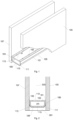
- Figure 1 shows a cross section of a spacer for creating a space between glass panes according to the invention.
- the spacer comprises a base body 100 which could be made by plastic, e.g. as a glass fibre reinforced polymeric base body 100.
- the base body comprises two parallel plate contact surfaces 101, 103 which make contact with the glass panes 105, 107.
- the spacer is a fibreglass reinforced polymeric base.
- a layer 115 is attached on the bonding surface 109.
- the layer has gas-impermeable characteristics, whereby gas diffusion through such a layer is at least reduced and could in one embodiment comprise multiple overlapping segments of a substantially gas-impermeable material.
- the layer could be attached to the base body 100 with PUR hot melt glue.
- Alternative methods of attaching a layer could be by adding a foil with a layer which is melted and then stiffened for attachment to the spacer.
- Figure 2 shows a cross section of a spacer according to the present invention positioned between glass panes.
- the spacer comprising the base body 100 and the layer 115 is positioned between a first pane 105 and a second pane 107.
- the layer 115 is positioned on the bonding surface 109 as well as on the connecting surfaces 111 and 113. Further, the layer continues at least partly upwards along the bonding surfaces 101 and 103, e.g. 2/3 of the height of the bonding surfaces.
- An adhesive layer is positioned between the contact surfaces 101, 103 of the spacer and the glass panes 105, 107. In an embodiment, this adhesive layer could comprise be butyl.
- the bonding between the bonding surfaces 101 and 103 and the panes is mainly to remove or reduce gas leak between the bonding surfaces 101, 103, 105, 107 and typically, butyl is used as a bonding agent to ensure this.
- the layer e.g. a foil layer
- the end point of the added layer is also covered by bonding agent, and this minimises the risk of gas leaks below the layer between the spacer surface and the layer.
- An insulating layer 201 is positioned in the space below the spacer and further ensures that the entire pane-spacer construction is mechanically stable and further, the layer 115 as well as an outer insulating layer 201 isolate the inner space 203 between the panes and reduce the heat transfer from the base body 100 into the inner space 203.
- the panes 105 and 107 have the same dimensions and thicknesses.
- drying means are positioned in the space 205 inside the base body.
- the drying means may be incorporated both within the central cavity of the base body 100 or in the material of the base body 100.
- the inner surface 110 of the base body comprises small openings or pores 102 allowing gas exchange with the inner space 203.
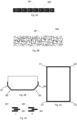
- Figs. 3A and 3B are illustrations of a layer with overlapping elements seen from the side and the top, respectively.
- a side view of a layer of segments is illustrated, and it can be seen how the segments overlap each other, e.g. by looking at segments 301 and 303.
- a top view of a layer of segments is illustrated, and it can be seen how the segments overlap each other, e.g. by looking at segments 301 and 303.
- the segments could be glass segments, such as ceramic segments, SiOx segments or similar.
- the segments should be in a material being substantially gas-impermeable in such a way that it reduces the gas diffusion through the spacer at least significantly.
- the segments in the layer could also be a combination of segments made from different materials, e.g. to obtain certain properties of the complete layer.
- the segments could be made from metal.
- Figures 3A and 3B are for illustrating the segments in the layer and more specifically to illustrate both how they overlap and how that they are positioned in a layer. The distance between segments as illustrated in figure 3A is much smaller than illustrated, where they could even touch each other to avoid gas leaking between segments. Further the segments are smaller than illustrated in figure 3B . In one embodiment, the segments could be positioned in a plastic substance.
- the stretching occurs due the mounting of the layer across an edge of the profile, e.g. such as the edges of the spacer shown in B1, B2, B3 and B4.
- the stretching occurs when bending a spacer, where foil has been mounted, e.g. to obtain the shape of panes to be separated by the spacer.
- FIG 4C a spacer, which has been shaped to be positioned between panes, is illustrated, where the spacer has been bent in each corner C1, C2, C3 and C4 for positioning between square shaped panes.
- Figs. 5A, 5B, 5C, 5D illustrate sub layers in a layer with gas-impermeable characteristics positioned on the surface of a spacer.
- Fig. 5A illustrates an embodiment of the layer mounted on the surface 501 of a spacer.
- the layer comprises a first sub layer 503 of overlapping segments, then a sub layer of polymeric material 505 and finally another sub layer of overlapping segments 503.
- a polymeric material between two segment layers e.g. as a glue
- any openings in the segment layer will be filled with polymeric material and thereby further enhance the insulation properties of the segment sub layers.
- a glue can be chosen having strong glass to glass capabilities. It is not two different materials that have to be connected which can result in a weak connection.
- Fig. 5B illustrates an embodiment of the layer mounted on the surface 501 of a spacer.
- the layer comprises a first sub layer 507 of PET and a second sub layer 503 of overlapping segments.
- the PET layer caries the segments and is mounted to the spacer surface afterwards.
- Fig. 5C illustrates an embodiment of the layer mounted on the surface 501 of a spacer.
- the layer comprises a first sub layer 507 of PET and a second sub layer 503 of overlapping segments and finally a third sub layer 507 of PET.
- the third PET sub layer protects the overlapping segments ensuring that the segments are not worn out during handling of the spacer with the layers.
- a further layer op either aluminum or glass could be added to ensure better connection properties of the spacer to the panes.
- Fig. 5D illustrates an embodiment of the layer mounted on the surface 501 of a spacer.
- the layer comprises a first sub layer 507 of PET and a second sub layer 503 of overlapping segments, a third sub layer of polymeric material 505, a fourth sub layer 503 of overlapping segments, a fifth sub layer 507 of PET and finally, a sixth sub layer 503 of overlapping segments.
Landscapes
- Engineering & Computer Science (AREA)
- Civil Engineering (AREA)
- Structural Engineering (AREA)
- Securing Of Glass Panes Or The Like (AREA)
- Joining Of Glass To Other Materials (AREA)
Description
- A plastic spacer comprising a layer with overlapping segments of a substantially gas-impermeable material.
- The present invention relates to a spacer for creating a spacing between glass panes. The present invention further relates to a method of manufacturing a spacer and a window comprising glass panes being mutually spaced by a spacer.
- It is well known to provide spacers in order to define the spacing between the panes of isolating glazings consisting of a plurality of parallel glass panes spaced by an isolating cavity.
- A plurality of such spacers made of different materials and in different shapes is known in the art. Spacers made by roll forming of a metal foil are widely used in the art and considered one of the preferred alternatives. This is because of their stability and their low gas diffusion properties.
- Insulating Glass Units (IG units) having a plurality of glass panes are made by automatic manufacturing machines. Spacers are automatically bent to the desired size and shape and are arranged between two neighboring glass panes. Spacers made of metal foils can be easily bent and will remain in the bent position.
- Furthermore, spacers made of metal foils have a high resistance against diffusion of gases and moisture penetration. Within the space between the neighboring glass panes, a gas is arranged, for instance argon, having good isolating properties. In order to avoid any loss of gas, the spacers delimiting the cavity need to be resistant against diffusion of such gaseous elements. Further, an advantage with metal spacers is that a good connection can be obtained between the glazing panes and the spacers due to glue being a good binder to both glass and metal.
- However, known spacers, which are exclusively made of metal such as aluminum and galvanized steel, also have some disadvantages. Due to a relatively high heat conductivity of metal, spacers made of a metal still have a heat conductivity which may be too high under certain circumstances.
- To reduce the heat conductivity, using plastic material for forming such spacers is possible. Plastic material has, however, relatively high gas diffusion as compared to metal. Further, it is difficult to obtain a good binding between the plastic spacers and the glazing panes which may result in the spacer loosing connection to the glazing panes over time. In order to solve this problem, a metal foil layer can be added to the plastic body and such a spacer is e.g. shown in
EP 852 280 - When adding foil to the surface of a spacer, the foil is added to cover both the lower surface as well as at least part of the side surface. This is done by adding a foil to the lower surface and then bending the foil upwards on each side. This bending of the foil can result in a weakening of the foil properties, whereby e.g. the argon gas between the pane layers may diffuse through such weak points.
- Further, when shaping spacers for glazing panes, the spacers are normally bent e.g. in four corners to obtain the squared shape of a pane. This bending of spacers made from plastic with a foil layer is problematic since the bending of the spacer could results in cracks in the thin foil layer, whereby properties of the profile is weakened at least in the corners and e.g. the argon gas between the pane layers diffuses through such cracks. Such a spacer is e.g. shown in
AU 2012/365 511 - In accordance with the invention, there is provided a spacer according to claim 1.
- Throughout this application when referring to segments, segments are to be understood as pieces of material having dimensions extending in at least one direction and typically comprising several particles of material. The segments could e.g. be flakes of material such as glass flakes, metal flakes or similar flakes of gas-impermeable material.
- The layer comprises multiple overlapping segments of a substantially gas-impermeable material. By letting the segments overlap, it is ensured that gas-impermeability of the spacer is significantly increased. Further, the overlapping of segments results in that a spacer with such a layer can be bent without compromising the gas-impermeability. When bending a spacer in corners to correspond to the shape of a glass pane, then the segments in the layer will still overlap, whereby gas-impermeability is maintained in the corners. Further, the overlapping ensures that a foil with such overlapping segments can be mounted across corners without compromising gas-impermeability.
- The layer is a foil layer comprising said segments. Thereby, the segments can be integrated in the foil, and the foil with segments can be made as a separate process.
- In an embodiment, the segments of substantially gas-impermeable material comprises glass. Glass has similar gas-impermeable characteristics as the glass panes resulting in a good insulation.
- In an embodiment, the layer comprises multiple sub layers of multiple overlapping segments of a substantially gas-impermeable material. Thereby, the gas-impermeability is further enhanced and by further adding other types of layers e.g. between the multiple sub layers, specific properties can be obtained.
- In an embodiment, a layer of polymeric material is present between a first and a second of said sub layers of multiple overlapping segments of a substantially gas-impermeable material. Thereby, the polymeric material, which could be a glue or another substance, further closes any gaps, which could be present between segments, and this enhances the gas-impermeability of the layer further.
- In an embodiment, the layer with gas-impermeable characteristics comprises multiple sub layers with a top sub layer contacting the spacer, and wherein at least the outermost sub layer comprises multiple overlapping segments of a substantially gas-impermeable material. Further, by adding segments to the outermost surface, segments could be chosen which further enhance the bonding properties of the outer surface of the spacer. For instance, if glass segments are added to the outermost surface of the spacer, then the main part of the outer surface of the spacer comprises glass and thereby, the connection between spacer and panes is a glass to glass connection, whereby a good bonding is possible since a material optimised for bonding glass can be used.
- Further, the invention relates to a method of producing a spacer according to the above, wherein said method comprises a step of adding a layer comprising multiple overlapping segments of a substantially gas-impermeable material.
- Further, the invention relates to a window comprising glass panes being mutually spaced by a spacer according to the above.
- The invention is explained in detail below with reference to the drawings, in which
-
Fig. 1 illustrates a cross section of a spacer according to the present invention, -
Fig. 2 illustrates a cross section of a spacer according to the present invention positioned between glass panes, -
Figs. 3A and 3B are illustrations of a layer with overlapping elements seen from the side and the top, respectively, -
Figs. 4A, 4B, 4C illustrate bends in connection with a spacer and the nature of the segment layer when positioned across such bends, -
Figs. 5A, 5B, 5C, 5D illustrate sub layers in a layer with gas-impermeable characteristics positioned on the surface of a spacer. -
Figure 1 shows a cross section of a spacer for creating a space between glass panes according to the invention. The spacer comprises abase body 100 which could be made by plastic, e.g. as a glass fibre reinforcedpolymeric base body 100. The base body comprises two parallel plate contact surfaces 101, 103 which make contact with theglass panes - The pane contact surfaces 103, 105 are connected between an
outer bonding surface 109 and aninner surface 110, and two angled connection surfaces 111, 113 are arranged between the bonding surfaces 103 and 105. Preferably, connectingsurfaces bonding surface 109. The angled shape of thefirst connection surface 111 and the second connectingsurface 113 improves the stability of the entire system, when glass panes have been mounted to thebase body 100 and allow, as shown inFigure 2 , a better adhesion and isolation of the spacer when mounted between glass panes. - On the
bonding surface 109, alayer 115 is attached. The layer has gas-impermeable characteristics, whereby gas diffusion through such a layer is at least reduced and could in one embodiment comprise multiple overlapping segments of a substantially gas-impermeable material. In one embodiment, the layer could be attached to thebase body 100 with PUR hot melt glue. Alternative methods of attaching a layer could be by adding a foil with a layer which is melted and then stiffened for attachment to the spacer. - In one embodiment, the segments of impermeable material could be glass segments, but alternative embodiments could be ceramic segments or other materials having a low gas-permeability.
-
Figure 2 shows a cross section of a spacer according to the present invention positioned between glass panes. The spacer comprising thebase body 100 and thelayer 115 is positioned between afirst pane 105 and asecond pane 107. In the illustrated embodiment, thelayer 115 is positioned on thebonding surface 109 as well as on the connectingsurfaces glass panes - An insulating
layer 201 is positioned in the space below the spacer and further ensures that the entire pane-spacer construction is mechanically stable and further, thelayer 115 as well as an outer insulatinglayer 201 isolate theinner space 203 between the panes and reduce the heat transfer from thebase body 100 into theinner space 203. - In the illustrated embodiment, the
panes space 205 inside the base body. - The drying means may be incorporated both within the central cavity of the
base body 100 or in the material of thebase body 100. Theinner surface 110 of the base body comprises small openings orpores 102 allowing gas exchange with theinner space 203. -
Figs. 3A and 3B are illustrations of a layer with overlapping elements seen from the side and the top, respectively. Infigure 3A , a side view of a layer of segments is illustrated, and it can be seen how the segments overlap each other, e.g. by looking atsegments figure 3B , a top view of a layer of segments is illustrated, and it can be seen how the segments overlap each other, e.g. by looking atsegments Figures 3A and 3B are for illustrating the segments in the layer and more specifically to illustrate both how they overlap and how that they are positioned in a layer. The distance between segments as illustrated infigure 3A is much smaller than illustrated, where they could even touch each other to avoid gas leaking between segments. Further the segments are smaller than illustrated infigure 3B . In one embodiment, the segments could be positioned in a plastic substance. -
Figs. 4A, 4B, 4C illustrate bends in connection with a spacer and the nature of the segment layer when positioned across such bends. Infigure 4A , overlapping segments are illustrated, where the segments are in a relaxed layer in I, wherein the same segments are in a stretched layer in II. From this illustration, it can be seen that due to the overlapping of the segments, the overlapping is maintained when stretched. Since the segments are of a substantially gas-impermeable material, the overlapping further ensures that gas cannot pass though the layer between the segments. - The stretching occurs due the mounting of the layer across an edge of the profile, e.g. such as the edges of the spacer shown in B1, B2, B3 and B4. Alternatively, the stretching occurs when bending a spacer, where foil has been mounted, e.g. to obtain the shape of panes to be separated by the spacer. In
figure 4C , a spacer, which has been shaped to be positioned between panes, is illustrated, where the spacer has been bent in each corner C1, C2, C3 and C4 for positioning between square shaped panes. -
Figs. 5A, 5B, 5C, 5D illustrate sub layers in a layer with gas-impermeable characteristics positioned on the surface of a spacer. -
Fig. 5A illustrates an embodiment of the layer mounted on thesurface 501 of a spacer. The layer comprises afirst sub layer 503 of overlapping segments, then a sub layer ofpolymeric material 505 and finally another sub layer of overlappingsegments 503. By adding a polymeric material between two segment layers, e.g. as a glue, any openings in the segment layer will be filled with polymeric material and thereby further enhance the insulation properties of the segment sub layers. It is further advantageous to end with a segment layer with e.g. glass segments since this surface is the surface that will be contacting the glue for mounting the panes to the profile and by having a glass material at the surface to be connected to glass panes, a glue can be chosen having strong glass to glass capabilities. It is not two different materials that have to be connected which can result in a weak connection. -
Fig. 5B illustrates an embodiment of the layer mounted on thesurface 501 of a spacer. The layer comprises afirst sub layer 507 of PET and asecond sub layer 503 of overlapping segments. Thereby, the PET layer caries the segments and is mounted to the spacer surface afterwards. -
Fig. 5C illustrates an embodiment of the layer mounted on thesurface 501 of a spacer. The layer comprises afirst sub layer 507 of PET and asecond sub layer 503 of overlapping segments and finally athird sub layer 507 of PET. Thereby, the third PET sub layer protects the overlapping segments ensuring that the segments are not worn out during handling of the spacer with the layers. A further layer op either aluminum or glass could be added to ensure better connection properties of the spacer to the panes. -
Fig. 5D illustrates an embodiment of the layer mounted on thesurface 501 of a spacer. The layer comprises afirst sub layer 507 of PET and asecond sub layer 503 of overlapping segments, a third sub layer ofpolymeric material 505, afourth sub layer 503 of overlapping segments, afifth sub layer 507 of PET and finally, asixth sub layer 503 of overlapping segments.
Claims (7)
- A spacer for creating a spacing between glass panes, wherein said spacer is made from a plastic material, said spacer being elongated and comprising two side surfaces as well as a top surface and a bottom surface, and wherein at least to the bottom surface of said spacer a layer with gas-impermeable characteristics has been added characterised in that said added layer is a foil layer comprising multiple overlapping segments of a substantially gas-impermeable material extending in at least one direction, such as flakes.
- A spacer according to claim 1, wherein said segments of substantially gas-impermeable material comprises glass.
- A spacer according to claim 1, wherein said layer comprises multiple sub layers of multiple overlapping segments of a substantially gas-impermeable material.
- A spacer according to claim 3, wherein a layer of polymeric material is present between a first and a second of said sub layers of multiple overlapping segments of a substantially gas-impermeable material
- A spacer according to claims 1-4, wherein said layer with gas-impermeable characteristics comprises multiple sub layers with a top sub layer contacting the spacer, and wherein at least the outermost sub layer comprises multiple overlapping segments of a substantially gas-impermeable material.
- A method of producing a spacer according to claims 1-5, wherein said method comprises a step of adding a layer comprising multiple overlapping segments of a substantially gas-impermeable material.
- A window comprising glass panes being mutually spaced by a spacer according to any of the claims 1-5.
Priority Applications (1)
| Application Number | Priority Date | Filing Date | Title |
|---|---|---|---|
| PL15778667.4T PL3207202T5 (en) | 2014-10-14 | 2015-10-12 | A plastic spacer comprising a layer with overlapping segments of a substantially gas-impermeable material |
Applications Claiming Priority (2)
| Application Number | Priority Date | Filing Date | Title |
|---|---|---|---|
| EP14188807.3A EP3009590A1 (en) | 2014-10-14 | 2014-10-14 | A plastic spacer comprising a layer with overlapping segments of a substantially gas-impermeable material |
| PCT/EP2015/073536 WO2016058977A1 (en) | 2014-10-14 | 2015-10-12 | A plastic spacer comprising a layer with overlapping segments of a substantially gas-impermeable material |
Publications (3)
| Publication Number | Publication Date |
|---|---|
| EP3207202A1 EP3207202A1 (en) | 2017-08-23 |
| EP3207202B1 EP3207202B1 (en) | 2019-01-30 |
| EP3207202B2 true EP3207202B2 (en) | 2023-12-06 |
Family
ID=51726397
Family Applications (2)
| Application Number | Title | Priority Date | Filing Date |
|---|---|---|---|
| EP14188807.3A Withdrawn EP3009590A1 (en) | 2014-10-14 | 2014-10-14 | A plastic spacer comprising a layer with overlapping segments of a substantially gas-impermeable material |
| EP15778667.4A Active EP3207202B2 (en) | 2014-10-14 | 2015-10-12 | A plastic spacer comprising a layer with overlapping segments of a substantially gas-impermeable material |
Family Applications Before (1)
| Application Number | Title | Priority Date | Filing Date |
|---|---|---|---|
| EP14188807.3A Withdrawn EP3009590A1 (en) | 2014-10-14 | 2014-10-14 | A plastic spacer comprising a layer with overlapping segments of a substantially gas-impermeable material |
Country Status (6)
| Country | Link |
|---|---|
| EP (2) | EP3009590A1 (en) |
| DE (1) | DE202015009966U1 (en) |
| DK (1) | DK3207202T4 (en) |
| HU (1) | HUE044087T2 (en) |
| PL (1) | PL3207202T5 (en) |
| WO (1) | WO2016058977A1 (en) |
Families Citing this family (1)
| Publication number | Priority date | Publication date | Assignee | Title |
|---|---|---|---|---|
| DE102016115023A1 (en) | 2015-12-23 | 2017-06-29 | Ensinger Gmbh | Spacers for insulating glass panes |
Citations (3)
| Publication number | Priority date | Publication date | Assignee | Title |
|---|---|---|---|---|
| EP1428657A1 (en) † | 2001-09-18 | 2004-06-16 | Tokuyama Corporation | Gas-barrier film and gas-barrier coating agent, and method for production thereof |
| WO2012100961A1 (en) † | 2011-01-25 | 2012-08-02 | Technoform Glass Insulation Holding Gmbh | Spacer profile and insulating glass unit comprising such a spacer |
| WO2013104507A1 (en) † | 2012-01-13 | 2013-07-18 | Saint-Gobain Glass France | Spacer for insulating glazing units |
Family Cites Families (1)
| Publication number | Priority date | Publication date | Assignee | Title |
|---|---|---|---|---|
| PT852280E (en) | 1996-12-20 | 2004-04-30 | Saint Gobain Vitrage Suisse Ag | ASPIRATOR FOR GLASS ISOLATION WITH VARIOUS GLASSES |
-
2014
- 2014-10-14 EP EP14188807.3A patent/EP3009590A1/en not_active Withdrawn
-
2015
- 2015-10-12 HU HUE15778667 patent/HUE044087T2/en unknown
- 2015-10-12 DE DE202015009966.1U patent/DE202015009966U1/en not_active Expired - Lifetime
- 2015-10-12 PL PL15778667.4T patent/PL3207202T5/en unknown
- 2015-10-12 WO PCT/EP2015/073536 patent/WO2016058977A1/en not_active Ceased
- 2015-10-12 DK DK15778667.4T patent/DK3207202T4/en active
- 2015-10-12 EP EP15778667.4A patent/EP3207202B2/en active Active
Patent Citations (3)
| Publication number | Priority date | Publication date | Assignee | Title |
|---|---|---|---|---|
| EP1428657A1 (en) † | 2001-09-18 | 2004-06-16 | Tokuyama Corporation | Gas-barrier film and gas-barrier coating agent, and method for production thereof |
| WO2012100961A1 (en) † | 2011-01-25 | 2012-08-02 | Technoform Glass Insulation Holding Gmbh | Spacer profile and insulating glass unit comprising such a spacer |
| WO2013104507A1 (en) † | 2012-01-13 | 2013-07-18 | Saint-Gobain Glass France | Spacer for insulating glazing units |
Also Published As
| Publication number | Publication date |
|---|---|
| WO2016058977A1 (en) | 2016-04-21 |
| PL3207202T5 (en) | 2024-12-09 |
| HUE044087T2 (en) | 2019-10-28 |
| DK3207202T4 (en) | 2024-02-12 |
| EP3207202B1 (en) | 2019-01-30 |
| EP3009590A1 (en) | 2016-04-20 |
| EP3207202A1 (en) | 2017-08-23 |
| DE202015009966U1 (en) | 2022-01-26 |
| PL3207202T3 (en) | 2019-07-31 |
| DK3207202T3 (en) | 2019-04-15 |
Similar Documents
| Publication | Publication Date | Title |
|---|---|---|
| EP2927904B1 (en) | Pyramid waffle core structure and method of fabrication | |
| KR101885418B1 (en) | Spacer for triple insulated glazing | |
| JP6479172B2 (en) | Spacer used for insulating glazing unit, insulating glazing unit having the spacer, manufacturing method and use of the spacer | |
| EP2260152B1 (en) | Vacuum-insulation element | |
| US8221857B2 (en) | Insulating glazing element, its manufacture and use | |
| US20110041427A1 (en) | Glazing panel | |
| JP6526812B2 (en) | Spacer for double glazing | |
| JP6505254B2 (en) | Method and apparatus for producing three layer double glazing | |
| JP2021517615A (en) | Spacer with reinforcing elements | |
| EP1891278B1 (en) | An insulating panel | |
| EP3207202B2 (en) | A plastic spacer comprising a layer with overlapping segments of a substantially gas-impermeable material | |
| US8776350B2 (en) | Spacer systems for insulated glass (IG) units, and/or methods of making the same | |
| KR101817669B1 (en) | Composite insulating and waterproofing structure and method using multi-layer composite waterproofing sheet | |
| CN114981076A (en) | Spacer comprising interrupted adhesive layer | |
| US20170368799A1 (en) | Vacuum insulation panel with improved sealing joint | |
| CN104341094B (en) | Energy-saving sheet material and manufacturing method thereof | |
| EP3301239B1 (en) | Wall construction element comprising a flat insulating element and at least one glass block | |
| US20080063839A1 (en) | Architectural glass block with a formed slot and method of making same | |
| US8871316B2 (en) | Insulated glass (IG) units including spacer systems, and/or methods of making the same | |
| EP2933544B1 (en) | Self-supporting air-conditioning duct | |
| CN204281555U (en) | Energy-conserving plate material | |
| CN210858441U (en) | Hollow glass and hollow glass product | |
| EP3653375B1 (en) | A method of producing an insulation board for a sandwich panel, an insulation board and a method for producing a sandwich panel | |
| KR102801510B1 (en) | Sandwich Panel Bending Method and Mobile Building using the Bending Panel bent by the above Method | |
| EP3309315B1 (en) | Laminated log |
Legal Events
| Date | Code | Title | Description |
|---|---|---|---|
| STAA | Information on the status of an ep patent application or granted ep patent |
Free format text: STATUS: THE INTERNATIONAL PUBLICATION HAS BEEN MADE |
|
| PUAI | Public reference made under article 153(3) epc to a published international application that has entered the european phase |
Free format text: ORIGINAL CODE: 0009012 |
|
| STAA | Information on the status of an ep patent application or granted ep patent |
Free format text: STATUS: REQUEST FOR EXAMINATION WAS MADE |
|
| 17P | Request for examination filed |
Effective date: 20170511 |
|
| AK | Designated contracting states |
Kind code of ref document: A1 Designated state(s): AL AT BE BG CH CY CZ DE DK EE ES FI FR GB GR HR HU IE IS IT LI LT LU LV MC MK MT NL NO PL PT RO RS SE SI SK SM TR |
|
| AX | Request for extension of the european patent |
Extension state: BA ME |
|
| DAV | Request for validation of the european patent (deleted) | ||
| DAX | Request for extension of the european patent (deleted) | ||
| GRAP | Despatch of communication of intention to grant a patent |
Free format text: ORIGINAL CODE: EPIDOSNIGR1 |
|
| STAA | Information on the status of an ep patent application or granted ep patent |
Free format text: STATUS: GRANT OF PATENT IS INTENDED |
|
| INTG | Intention to grant announced |
Effective date: 20181011 |
|
| RAP1 | Party data changed (applicant data changed or rights of an application transferred) |
Owner name: ROLLTECH A/S |
|
| GRAS | Grant fee paid |
Free format text: ORIGINAL CODE: EPIDOSNIGR3 |
|
| GRAA | (expected) grant |
Free format text: ORIGINAL CODE: 0009210 |
|
| STAA | Information on the status of an ep patent application or granted ep patent |
Free format text: STATUS: THE PATENT HAS BEEN GRANTED |
|
| AK | Designated contracting states |
Kind code of ref document: B1 Designated state(s): AL AT BE BG CH CY CZ DE DK EE ES FI FR GB GR HR HU IE IS IT LI LT LU LV MC MK MT NL NO PL PT RO RS SE SI SK SM TR |
|
| REG | Reference to a national code |
Ref country code: GB Ref legal event code: FG4D |
|
| REG | Reference to a national code |
Ref country code: CH Ref legal event code: EP |
|
| REG | Reference to a national code |
Ref country code: AT Ref legal event code: REF Ref document number: 1093410 Country of ref document: AT Kind code of ref document: T Effective date: 20190215 |
|
| REG | Reference to a national code |
Ref country code: IE Ref legal event code: FG4D |
|
| REG | Reference to a national code |
Ref country code: DE Ref legal event code: R096 Ref document number: 602015024085 Country of ref document: DE |
|
| REG | Reference to a national code |
Ref country code: DK Ref legal event code: T3 Effective date: 20190408 |
|
| REG | Reference to a national code |
Ref country code: LT Ref legal event code: MG4D |
|
| REG | Reference to a national code |
Ref country code: NL Ref legal event code: MP Effective date: 20190130 |
|
| PG25 | Lapsed in a contracting state [announced via postgrant information from national office to epo] |
Ref country code: PT Free format text: LAPSE BECAUSE OF FAILURE TO SUBMIT A TRANSLATION OF THE DESCRIPTION OR TO PAY THE FEE WITHIN THE PRESCRIBED TIME-LIMIT Effective date: 20190530 Ref country code: SE Free format text: LAPSE BECAUSE OF FAILURE TO SUBMIT A TRANSLATION OF THE DESCRIPTION OR TO PAY THE FEE WITHIN THE PRESCRIBED TIME-LIMIT Effective date: 20190130 Ref country code: NO Free format text: LAPSE BECAUSE OF FAILURE TO SUBMIT A TRANSLATION OF THE DESCRIPTION OR TO PAY THE FEE WITHIN THE PRESCRIBED TIME-LIMIT Effective date: 20190430 Ref country code: NL Free format text: LAPSE BECAUSE OF FAILURE TO SUBMIT A TRANSLATION OF THE DESCRIPTION OR TO PAY THE FEE WITHIN THE PRESCRIBED TIME-LIMIT Effective date: 20190130 Ref country code: LT Free format text: LAPSE BECAUSE OF FAILURE TO SUBMIT A TRANSLATION OF THE DESCRIPTION OR TO PAY THE FEE WITHIN THE PRESCRIBED TIME-LIMIT Effective date: 20190130 Ref country code: ES Free format text: LAPSE BECAUSE OF FAILURE TO SUBMIT A TRANSLATION OF THE DESCRIPTION OR TO PAY THE FEE WITHIN THE PRESCRIBED TIME-LIMIT Effective date: 20190130 |
|
| REG | Reference to a national code |
Ref country code: AT Ref legal event code: MK05 Ref document number: 1093410 Country of ref document: AT Kind code of ref document: T Effective date: 20190130 |
|
| PG25 | Lapsed in a contracting state [announced via postgrant information from national office to epo] |
Ref country code: IS Free format text: LAPSE BECAUSE OF FAILURE TO SUBMIT A TRANSLATION OF THE DESCRIPTION OR TO PAY THE FEE WITHIN THE PRESCRIBED TIME-LIMIT Effective date: 20190530 Ref country code: LV Free format text: LAPSE BECAUSE OF FAILURE TO SUBMIT A TRANSLATION OF THE DESCRIPTION OR TO PAY THE FEE WITHIN THE PRESCRIBED TIME-LIMIT Effective date: 20190130 Ref country code: GR Free format text: LAPSE BECAUSE OF FAILURE TO SUBMIT A TRANSLATION OF THE DESCRIPTION OR TO PAY THE FEE WITHIN THE PRESCRIBED TIME-LIMIT Effective date: 20190501 Ref country code: HR Free format text: LAPSE BECAUSE OF FAILURE TO SUBMIT A TRANSLATION OF THE DESCRIPTION OR TO PAY THE FEE WITHIN THE PRESCRIBED TIME-LIMIT Effective date: 20190130 Ref country code: BG Free format text: LAPSE BECAUSE OF FAILURE TO SUBMIT A TRANSLATION OF THE DESCRIPTION OR TO PAY THE FEE WITHIN THE PRESCRIBED TIME-LIMIT Effective date: 20190430 Ref country code: RS Free format text: LAPSE BECAUSE OF FAILURE TO SUBMIT A TRANSLATION OF THE DESCRIPTION OR TO PAY THE FEE WITHIN THE PRESCRIBED TIME-LIMIT Effective date: 20190130 |
|
| REG | Reference to a national code |
Ref country code: HU Ref legal event code: AG4A Ref document number: E044087 Country of ref document: HU |
|
| REG | Reference to a national code |
Ref country code: DE Ref legal event code: R026 Ref document number: 602015024085 Country of ref document: DE |
|
| PG25 | Lapsed in a contracting state [announced via postgrant information from national office to epo] |
Ref country code: RO Free format text: LAPSE BECAUSE OF FAILURE TO SUBMIT A TRANSLATION OF THE DESCRIPTION OR TO PAY THE FEE WITHIN THE PRESCRIBED TIME-LIMIT Effective date: 20190130 Ref country code: EE Free format text: LAPSE BECAUSE OF FAILURE TO SUBMIT A TRANSLATION OF THE DESCRIPTION OR TO PAY THE FEE WITHIN THE PRESCRIBED TIME-LIMIT Effective date: 20190130 Ref country code: AL Free format text: LAPSE BECAUSE OF FAILURE TO SUBMIT A TRANSLATION OF THE DESCRIPTION OR TO PAY THE FEE WITHIN THE PRESCRIBED TIME-LIMIT Effective date: 20190130 Ref country code: SK Free format text: LAPSE BECAUSE OF FAILURE TO SUBMIT A TRANSLATION OF THE DESCRIPTION OR TO PAY THE FEE WITHIN THE PRESCRIBED TIME-LIMIT Effective date: 20190130 |
|
| PLBI | Opposition filed |
Free format text: ORIGINAL CODE: 0009260 |
|
| PLAX | Notice of opposition and request to file observation + time limit sent |
Free format text: ORIGINAL CODE: EPIDOSNOBS2 |
|
| PLAB | Opposition data, opponent's data or that of the opponent's representative modified |
Free format text: ORIGINAL CODE: 0009299OPPO |
|
| PG25 | Lapsed in a contracting state [announced via postgrant information from national office to epo] |
Ref country code: SM Free format text: LAPSE BECAUSE OF FAILURE TO SUBMIT A TRANSLATION OF THE DESCRIPTION OR TO PAY THE FEE WITHIN THE PRESCRIBED TIME-LIMIT Effective date: 20190130 |
|
| 26 | Opposition filed |
Opponent name: TECHNOFORM GLASS INSULATION HOLDING GMBH Effective date: 20191030 |
|
| R26 | Opposition filed (corrected) |
Opponent name: TECHNOFORM GLASS INSULATION HOLDING GMBH Effective date: 20191030 |
|
| PG25 | Lapsed in a contracting state [announced via postgrant information from national office to epo] |
Ref country code: AT Free format text: LAPSE BECAUSE OF FAILURE TO SUBMIT A TRANSLATION OF THE DESCRIPTION OR TO PAY THE FEE WITHIN THE PRESCRIBED TIME-LIMIT Effective date: 20190130 |
|
| PG25 | Lapsed in a contracting state [announced via postgrant information from national office to epo] |
Ref country code: SI Free format text: LAPSE BECAUSE OF FAILURE TO SUBMIT A TRANSLATION OF THE DESCRIPTION OR TO PAY THE FEE WITHIN THE PRESCRIBED TIME-LIMIT Effective date: 20190130 |
|
| PG25 | Lapsed in a contracting state [announced via postgrant information from national office to epo] |
Ref country code: TR Free format text: LAPSE BECAUSE OF FAILURE TO SUBMIT A TRANSLATION OF THE DESCRIPTION OR TO PAY THE FEE WITHIN THE PRESCRIBED TIME-LIMIT Effective date: 20190130 |
|
| PLBB | Reply of patent proprietor to notice(s) of opposition received |
Free format text: ORIGINAL CODE: EPIDOSNOBS3 |
|
| REG | Reference to a national code |
Ref country code: FI Ref legal event code: MAE |
|
| PG25 | Lapsed in a contracting state [announced via postgrant information from national office to epo] |
Ref country code: MC Free format text: LAPSE BECAUSE OF FAILURE TO SUBMIT A TRANSLATION OF THE DESCRIPTION OR TO PAY THE FEE WITHIN THE PRESCRIBED TIME-LIMIT Effective date: 20190130 |
|
| REG | Reference to a national code |
Ref country code: CH Ref legal event code: PL |
|
| PG25 | Lapsed in a contracting state [announced via postgrant information from national office to epo] |
Ref country code: LU Free format text: LAPSE BECAUSE OF NON-PAYMENT OF DUE FEES Effective date: 20191012 Ref country code: LI Free format text: LAPSE BECAUSE OF NON-PAYMENT OF DUE FEES Effective date: 20191031 Ref country code: CH Free format text: LAPSE BECAUSE OF NON-PAYMENT OF DUE FEES Effective date: 20191031 Ref country code: FI Free format text: LAPSE BECAUSE OF NON-PAYMENT OF DUE FEES Effective date: 20191012 |
|
| REG | Reference to a national code |
Ref country code: BE Ref legal event code: MM Effective date: 20191031 |
|
| PG25 | Lapsed in a contracting state [announced via postgrant information from national office to epo] |
Ref country code: BE Free format text: LAPSE BECAUSE OF NON-PAYMENT OF DUE FEES Effective date: 20191031 |
|
| PG25 | Lapsed in a contracting state [announced via postgrant information from national office to epo] |
Ref country code: IE Free format text: LAPSE BECAUSE OF NON-PAYMENT OF DUE FEES Effective date: 20191012 |
|
| PG25 | Lapsed in a contracting state [announced via postgrant information from national office to epo] |
Ref country code: CY Free format text: LAPSE BECAUSE OF FAILURE TO SUBMIT A TRANSLATION OF THE DESCRIPTION OR TO PAY THE FEE WITHIN THE PRESCRIBED TIME-LIMIT Effective date: 20190130 |
|
| PG25 | Lapsed in a contracting state [announced via postgrant information from national office to epo] |
Ref country code: MT Free format text: LAPSE BECAUSE OF FAILURE TO SUBMIT A TRANSLATION OF THE DESCRIPTION OR TO PAY THE FEE WITHIN THE PRESCRIBED TIME-LIMIT Effective date: 20190130 |
|
| APBM | Appeal reference recorded |
Free format text: ORIGINAL CODE: EPIDOSNREFNO |
|
| APBP | Date of receipt of notice of appeal recorded |
Free format text: ORIGINAL CODE: EPIDOSNNOA2O |
|
| APAH | Appeal reference modified |
Free format text: ORIGINAL CODE: EPIDOSCREFNO |
|
| RAP4 | Party data changed (patent owner data changed or rights of a patent transferred) |
Owner name: ROLLTECH A/S |
|
| APBQ | Date of receipt of statement of grounds of appeal recorded |
Free format text: ORIGINAL CODE: EPIDOSNNOA3O |
|
| PG25 | Lapsed in a contracting state [announced via postgrant information from national office to epo] |
Ref country code: MK Free format text: LAPSE BECAUSE OF FAILURE TO SUBMIT A TRANSLATION OF THE DESCRIPTION OR TO PAY THE FEE WITHIN THE PRESCRIBED TIME-LIMIT Effective date: 20190130 |
|
| P01 | Opt-out of the competence of the unified patent court (upc) registered |
Effective date: 20230601 |
|
| APAH | Appeal reference modified |
Free format text: ORIGINAL CODE: EPIDOSCREFNO |
|
| APBU | Appeal procedure closed |
Free format text: ORIGINAL CODE: EPIDOSNNOA9O |
|
| PUAH | Patent maintained in amended form |
Free format text: ORIGINAL CODE: 0009272 |
|
| STAA | Information on the status of an ep patent application or granted ep patent |
Free format text: STATUS: PATENT MAINTAINED AS AMENDED |
|
| 27A | Patent maintained in amended form |
Effective date: 20231206 |
|
| AK | Designated contracting states |
Kind code of ref document: B2 Designated state(s): AL AT BE BG CH CY CZ DE DK EE ES FI FR GB GR HR HU IE IS IT LI LT LU LV MC MK MT NL NO PL PT RO RS SE SI SK SM TR |
|
| REG | Reference to a national code |
Ref country code: DE Ref legal event code: R102 Ref document number: 602015024085 Country of ref document: DE |
|
| REG | Reference to a national code |
Ref country code: DK Ref legal event code: T4 Effective date: 20240209 |
|
| REG | Reference to a national code |
Ref country code: HU Ref legal event code: HC9C Owner name: ROLLTECH A/S, DK Free format text: FORMER OWNER(S): ROLLTECH A/S, DK |
|
| PGFP | Annual fee paid to national office [announced via postgrant information from national office to epo] |
Ref country code: DK Payment date: 20250922 Year of fee payment: 11 |
|
| PGFP | Annual fee paid to national office [announced via postgrant information from national office to epo] |
Ref country code: PL Payment date: 20250925 Year of fee payment: 11 |
|
| PGFP | Annual fee paid to national office [announced via postgrant information from national office to epo] |
Ref country code: GB Payment date: 20250922 Year of fee payment: 11 |
|
| PGFP | Annual fee paid to national office [announced via postgrant information from national office to epo] |
Ref country code: HU Payment date: 20251009 Year of fee payment: 11 |
|
| PGFP | Annual fee paid to national office [announced via postgrant information from national office to epo] |
Ref country code: DE Payment date: 20250923 Year of fee payment: 11 |
|
| PGFP | Annual fee paid to national office [announced via postgrant information from national office to epo] |
Ref country code: IT Payment date: 20251021 Year of fee payment: 11 |
|
| PGFP | Annual fee paid to national office [announced via postgrant information from national office to epo] |
Ref country code: FR Payment date: 20251011 Year of fee payment: 11 |
|
| PGFP | Annual fee paid to national office [announced via postgrant information from national office to epo] |
Ref country code: CZ Payment date: 20251009 Year of fee payment: 11 |