EP3206850B1 - Beschichtung einer rohrverbindung - Google Patents
Beschichtung einer rohrverbindung Download PDFInfo
- Publication number
- EP3206850B1 EP3206850B1 EP15850704.6A EP15850704A EP3206850B1 EP 3206850 B1 EP3206850 B1 EP 3206850B1 EP 15850704 A EP15850704 A EP 15850704A EP 3206850 B1 EP3206850 B1 EP 3206850B1
- Authority
- EP
- European Patent Office
- Prior art keywords
- coating
- field joint
- parent
- backs
- cut back
- Prior art date
- Legal status (The legal status is an assumption and is not a legal conclusion. Google has not performed a legal analysis and makes no representation as to the accuracy of the status listed.)
- Active
Links
Images


Classifications
-
- B—PERFORMING OPERATIONS; TRANSPORTING
- B29—WORKING OF PLASTICS; WORKING OF SUBSTANCES IN A PLASTIC STATE IN GENERAL
- B29C—SHAPING OR JOINING OF PLASTICS; SHAPING OF MATERIAL IN A PLASTIC STATE, NOT OTHERWISE PROVIDED FOR; AFTER-TREATMENT OF THE SHAPED PRODUCTS, e.g. REPAIRING
- B29C45/00—Injection moulding, i.e. forcing the required volume of moulding material through a nozzle into a closed mould; Apparatus therefor
- B29C45/14—Injection moulding, i.e. forcing the required volume of moulding material through a nozzle into a closed mould; Apparatus therefor incorporating preformed parts or layers, e.g. injection moulding around inserts or for coating articles
- B29C45/14467—Joining articles or parts of a single article
- B29C45/14491—Injecting material between coaxial articles, e.g. between a core and an outside sleeve for making a roll
-
- B—PERFORMING OPERATIONS; TRANSPORTING
- B29—WORKING OF PLASTICS; WORKING OF SUBSTANCES IN A PLASTIC STATE IN GENERAL
- B29C—SHAPING OR JOINING OF PLASTICS; SHAPING OF MATERIAL IN A PLASTIC STATE, NOT OTHERWISE PROVIDED FOR; AFTER-TREATMENT OF THE SHAPED PRODUCTS, e.g. REPAIRING
- B29C45/00—Injection moulding, i.e. forcing the required volume of moulding material through a nozzle into a closed mould; Apparatus therefor
- B29C45/14—Injection moulding, i.e. forcing the required volume of moulding material through a nozzle into a closed mould; Apparatus therefor incorporating preformed parts or layers, e.g. injection moulding around inserts or for coating articles
- B29C45/14336—Coating a portion of the article, e.g. the edge of the article
-
- B—PERFORMING OPERATIONS; TRANSPORTING
- B29—WORKING OF PLASTICS; WORKING OF SUBSTANCES IN A PLASTIC STATE IN GENERAL
- B29C—SHAPING OR JOINING OF PLASTICS; SHAPING OF MATERIAL IN A PLASTIC STATE, NOT OTHERWISE PROVIDED FOR; AFTER-TREATMENT OF THE SHAPED PRODUCTS, e.g. REPAIRING
- B29C45/00—Injection moulding, i.e. forcing the required volume of moulding material through a nozzle into a closed mould; Apparatus therefor
- B29C45/14—Injection moulding, i.e. forcing the required volume of moulding material through a nozzle into a closed mould; Apparatus therefor incorporating preformed parts or layers, e.g. injection moulding around inserts or for coating articles
- B29C45/14598—Coating tubular articles
- B29C45/14614—Joining tubular articles
-
- F—MECHANICAL ENGINEERING; LIGHTING; HEATING; WEAPONS; BLASTING
- F16—ENGINEERING ELEMENTS AND UNITS; GENERAL MEASURES FOR PRODUCING AND MAINTAINING EFFECTIVE FUNCTIONING OF MACHINES OR INSTALLATIONS; THERMAL INSULATION IN GENERAL
- F16L—PIPES; JOINTS OR FITTINGS FOR PIPES; SUPPORTS FOR PIPES, CABLES OR PROTECTIVE TUBING; MEANS FOR THERMAL INSULATION IN GENERAL
- F16L13/00—Non-disconnectable pipe joints, e.g. soldered, adhesive, or caulked joints
- F16L13/02—Welded joints
- F16L13/0254—Welded joints the pipes having an internal or external coating
- F16L13/0272—Welded joints the pipes having an internal or external coating having an external coating
-
- F—MECHANICAL ENGINEERING; LIGHTING; HEATING; WEAPONS; BLASTING
- F16—ENGINEERING ELEMENTS AND UNITS; GENERAL MEASURES FOR PRODUCING AND MAINTAINING EFFECTIVE FUNCTIONING OF MACHINES OR INSTALLATIONS; THERMAL INSULATION IN GENERAL
- F16L—PIPES; JOINTS OR FITTINGS FOR PIPES; SUPPORTS FOR PIPES, CABLES OR PROTECTIVE TUBING; MEANS FOR THERMAL INSULATION IN GENERAL
- F16L58/00—Protection of pipes or pipe fittings against corrosion or incrustation
- F16L58/02—Protection of pipes or pipe fittings against corrosion or incrustation by means of internal or external coatings
- F16L58/04—Coatings characterised by the materials used
- F16L58/10—Coatings characterised by the materials used by rubber or plastics
- F16L58/1054—Coatings characterised by the materials used by rubber or plastics the coating being placed outside the pipe
-
- F—MECHANICAL ENGINEERING; LIGHTING; HEATING; WEAPONS; BLASTING
- F16—ENGINEERING ELEMENTS AND UNITS; GENERAL MEASURES FOR PRODUCING AND MAINTAINING EFFECTIVE FUNCTIONING OF MACHINES OR INSTALLATIONS; THERMAL INSULATION IN GENERAL
- F16L—PIPES; JOINTS OR FITTINGS FOR PIPES; SUPPORTS FOR PIPES, CABLES OR PROTECTIVE TUBING; MEANS FOR THERMAL INSULATION IN GENERAL
- F16L58/00—Protection of pipes or pipe fittings against corrosion or incrustation
- F16L58/18—Protection of pipes or pipe fittings against corrosion or incrustation specially adapted for pipe fittings
- F16L58/181—Protection of pipes or pipe fittings against corrosion or incrustation specially adapted for pipe fittings for non-disconnectable pipe joints
-
- B—PERFORMING OPERATIONS; TRANSPORTING
- B29—WORKING OF PLASTICS; WORKING OF SUBSTANCES IN A PLASTIC STATE IN GENERAL
- B29K—INDEXING SCHEME ASSOCIATED WITH SUBCLASSES B29B, B29C OR B29D, RELATING TO MOULDING MATERIALS OR TO MATERIALS FOR MOULDS, REINFORCEMENTS, FILLERS OR PREFORMED PARTS, e.g. INSERTS
- B29K2023/00—Use of polyalkenes or derivatives thereof as moulding material
- B29K2023/10—Polymers of propylene
- B29K2023/12—PP, i.e. polypropylene
-
- B—PERFORMING OPERATIONS; TRANSPORTING
- B29—WORKING OF PLASTICS; WORKING OF SUBSTANCES IN A PLASTIC STATE IN GENERAL
- B29L—INDEXING SCHEME ASSOCIATED WITH SUBCLASS B29C, RELATING TO PARTICULAR ARTICLES
- B29L2023/00—Tubular articles
- B29L2023/22—Tubes or pipes, i.e. rigid
Definitions
- the present disclosure is related to a method of coating a field joint for insulated pipelines, pipe sections for forming such coated field joints, and pipelines having such coated field joints.
- the present disclosure may be relevant to onshore and/or offshore, oil and gas pipelines.
- pipe sections which are factory-coated with an elastomer and/or insulation coating are not fully coated along their entire lengths, but rather are left with uncoated ends to facilitate joining of the pipe section ends (e.g., using a welding process) in the field.
- Each uncoated end on a pipe section may be about 200mm in length.
- the pipe sections are typically welded together as part of the pipe laying process. This welding may take place at the location where the pipe sections are to be reeled, or, such as in the case of sub-sea or offshore pipes, on a lay barge or a reel ship.
- the field joint coating is typically an insulation material that is typically different than, but having similar properties as, the parent coating provided on the pipe section at the factory.
- the field joint coating is typically applied using an injection moulding process in which the field joint coating is injected into a mould placed about the field joint and overlapping with the parent coating.
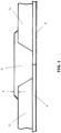
- the result is typically a coated field joint as shown in the longitudinal cross-sectional view of FIG. 1 .
- This example illustrates a field joint between two pipe sections A and B, each having factory-applied parent coatings C A and C B , respectively.
- the field joint coating D typically fills in the gap between the parent coatings C A and C B , and also overlaps the parent coatings C A and C B . This overlap means that the field joint coating D has a greater radius than the parent coatings C A and C B , and this difference is referred to as the upstand E.
- the upstand may be 8mm or greater.
- the presence of a large upstand e.g., an upstand that is 8mm or greater
- PCT international patent application published as WO 2012/168149 A1 discloses a process for coating a field joint.
- Two pipes which are coated with an epoxy layer, an adhesive layer and polypropylene layers are provided. Cut backs are provided on the epoxy layer, the adhesive layer and the polypropylene layers. The ends of pipes are welded together, forming a field joint.
- the field joint is coated with an epoxy layer and an adhesive layer and a field joint coating is then applied to the coated field joint and the cut back.
- PCT international patent application published as WO 2013/066170 A1 discloses a method for coating a field joint.
- the pipes are coated with a layer of anti-corrosion agent and a layer of coating. Cut backs are provided on each layer.
- the cut back in the anti-corrosion agent layer is perpendicular to the surface of the pipe, while the cut back in the coating layer is angular.
- a coating layer is applied at the pipe joint, covering the field joint and the cut backs.
- the present disclosure provides a method of coating a field joint joining uncoated ends of two pipe sections, each pipe section being coated with a parent coating and having at least one uncoated end, the method including: providing a first angular cut back in the parent coating of each pipe section, the first angular cut back being at an angle of about 30° ⁇ 5° relative to a longitudinal axis of the field joint; providing a second angular cut back in the parent coating of each pipe section, the second angular cut back being positioned further from the field joint than the first angular cut back; the first and second angular cut backs resulting in the parent coating having a stepped profile, a step in the stepped profile being defined between the first and second angular cut backs, the step being substantially parallel to the longitudinal axis of the field joint and being free of indentations; and injection moulding a field joint coating over the uncoated ends and the first and second angular cut backs, the field joint coating being moulded to have an upstand that is less
- the present disclosure provides a pipe section for forming a field joint, the pipe section including: a pipe section end to be joined with another pipe section end for forming the field joint; and a parent coating over an outer surface of the pipe section, the outer surface in the vicinity of the pipe section end being free of the parent coating; the parent coating in the vicinity of the pipe section end having provided therein first and second angular cut backs, the first angular cut back being at an angle of between 20° and 45° with a manufacturing tolerance of +/- 5°, for example, about 30° ⁇ 5°, relative to a longitudinal axis of the pipe section and the second angular cut back being positioned further from the pipe section end than the first angular cut back; the first and second angular cut backs resulting in the parent coating having a stepped profile, a step in the stepped profile being defined between the first and second angular cut backs, the step being substantially parallel to the longitudinal axis of the pipe section and being free of indentations.
- the present disclosure provides a coated field joint joining ends of two pipe sections, the coated field joint including: a field joint joining the ends of the two pipe sections, each of the two pipe sections being as described above; and a field joint coating over the field joint and the first and second angular cut backs, the field joint coating forming an upstand that is less than or equal to about 5mm.
- the present disclosure provides methods for coating a field joint, coated field joints formed thereby and pipe sections for forming such coated field joints.
- the coated field joint in accordance with the present disclosure may achieve an upstand that is substantially flush with the parent coating on the pipe section, or that is minimal (e.g., 5mm or less).
- the present disclosure may enable a coated field joint that uses a smaller volume of field joint coating material.
- a field joint that is flush with the parent coating or that has a reduced upstand may enable easier handling in the yard and/or on the vessel prior to laying of the pipe, may help to reduce the risk of damage to laying equipment (e.g., tensioners on reel-lay vessels), and/or may enable more pipe to be reeled (due to the smaller diameter of the disclosure coated field joint, compared to conventional coated field joint).
- laying equipment e.g., tensioners on reel-lay vessels
- FIG. 2 shows a cross-sectional view of a coated field joint in accordance with an example of the present disclosure.
- two pipe sections 2, 4 are joined together at their respective ends 6, 8.
- ends 6, 8 For simplicity, details will be described only for one side of the field joint corresponding to pipe section 2, however it should be understood that the configuration is the same for the other side of the field joint corresponding to pipe section 4.
- the pipe section 2 is provided with a parent coating 10, which may have been applied at a manufacturing site, such as a factory.
- the parent coating 10 may be any thermoplastic or thermosetting material.
- the parent coating 10 may be a multi-layered coating.
- the parent coating 10 may include an inner anti-corrosion layer (e.g., a polyurethane or epoxy layer), a middle insulation layer (e.g., a foamed or unfoamed polypropylene layer) and an outer protective layer (e.g., an unfoamed polypropylene, polyurethane, epoxy resin or rubber layer).
- an inner anti-corrosion layer e.g., a polyurethane or epoxy layer
- a middle insulation layer e.g., a foamed or unfoamed polypropylene layer
- an outer protective layer e.g., an unfoamed polypropylene, polyurethane, epoxy resin or rubber layer.
- Different single-layered or multi-layered coatings may be used
- the parent coating 10, as initially applied at the factory, may leave the end 6 of the pipe section 2 uncoated, for example about 200mm from each end of the pipe section 2 may be free of the parent coating 10.
- the parent coating 10 may end abruptly or gradually (e.g., taper off) near the ends of the pipe section 2.
- the field joint is formed by joining (e.g., by welding) the uncoated ends 6, 8 of the pipe sections 2, 4.
- the pipe sections 2, 4 in the vicinity of the joint are uncoated.
- the joint may be coated by a field joint coating, as described below. Prior to application of the field joint coating, cut backs may be made in the parent coating 10, as described below.
- a first angular cut back 102 is provided in the parent coating 10.
- the first cut back 102 may be made using any suitable technique, such as by a grinding process or a lathing method.
- the first cut back 102 is provided at an angle x relative to the longitudinal axis L of the field joint (which may also be the longitudinal axis of the pipe sections 2, 4).
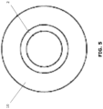
- the first cut back 102 is provided about the entire circumference of the pipe section 2, resulting in a frustoconical shape (see FIG. 3 ).
- a second angular cut back 104 is provided in the parent coating 10.
- the second cut back may be made using any suitable technique (which may be the same or different from that used for the first cut back 102), such as by a grinding process or a bevelling method.
- the second cut back 104 is provided further away from the end 6 than the first cut back 102, resulting in a stepped profile, as shown in the cross-sectional view of FIG. 2 .
- the second cut back 104 is provided at an angle y relative to the longitudinal axis L of the field joint.
- the angle y may be the same as or different from the angle x of the first cut back 102.
- the second cut back 104 is provided about the entire circumference of the pipe section 2 (see FIG. 3 ).
- the second cut back 104 is made to a depth h 2 that is less than the entire thickness of the parent coating 10.
- the first and second cut backs 102, 104 form a stepped profile, with the first cut back 102 forming an incline at an angle x to a height of h 1 , the second cut back 104 forming an incline at an angle y to a height of h 2 , and a step 106 of length l 1 , substantially parallel to the longitudinal axis L, being defined between the first and second cut backs 102, 104.
- the surface of the step 106 is substantially free of indentations or grooves. Further details about the dimensions of the cut backs 102, 104 are described below.
- a field joint coating 108 may be injection moulded over the uncoated ends 6, 8 and the first and second cut backs 102, 104.
- the field joint coating 108 may be any suitable material, including any thermoplastic or thermosetting material typically known and used for such applications, for example including an insulation material similar to or same as the insulation layer of the parent coating 10 (e.g., a foamed or unfoamed polypropylene material). Other materials may be suitable for the field joint coating 108, including materials suitable for high temperature applications.
- the field joint coating 108 may extend past the second cut back 104 and cover the parent coating 10 to a distance l 2 , and may have an upstand 110 of less than or equal to about 5mm.
- the upstand 110 may be substantially 0mm (in which case the distance l 2 may be substantially 0mm).
- a mould (not shown) may be positioned about the first and second cut backs 102, 104 on both pipe sections 2, 4 and including the welded field joint.
- the field joint coating 108 may be injected into the mould.
- the injection moulding process may be carried out at a sufficient temperature and/or pressure to ensure that the field joint coating 108 fully fills in the mould and fully covers the exposed surfaces of the pipe sections 2, 4, the cut backs 102, 104, and the step 106 (and optionally a portion of the parent coating 10 to a distance l 2 ).
- the mould may be preheated, for example to about 70°C, which may help with setting and/or curing of the field joint coating 108.
- the mould may be removed after the field joint coating 108 has set and/or cured. In some examples, the mould may be removed when the field joint coating 108 is partly or mostly set and/or cured, and full setting and/or curing of the field joint coating 108 may occur without the mould.
- the exposed surfaces of the first and second cut backs 102, 104 and the step 106 may be pre-treated prior to injection moulding the field joint coating 108.
- one or more such surfaces may be cleaned (e.g., using a solvent, such as xylene).
- exposed metal surfaces of the pipe sections 2, 4 in the vicinity of the welded field joint may be heated (e.g., using an induction heating coil), such as to a temperature in the range of about 70°C to about 90°C.
- a primer which may improve binding of the field joint coating 108, may be applied to the heated or unheated metal surfaces.
- exposed surfaces of the first and second cut backs 102, 104 and the step 106 may be abraded (e.g., using a grinder).
- the surfaces of the first and second cut backs 102, 104 and the step 106 (and optionally uncut portions of the parent coating 10 near the second cut back 104 that may be coated by the field joint coating 108) may be flame treated and may be coated with a primer.
- the entire area to be coated by the field joint coating 108 may be flame treated and/or primed with a primer.
- One or more of these pre-treatments may be used in combination. The pre-treatments may help the field joint coating 108 to better bond to the exposed surfaces of the pipe sections 2, 4, the cut backs 102, 104, and the step 106.
- a quality check may be performed to ensure that the upstand 110 is within acceptable values (e.g., less than or equal to 5mm).
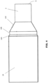
- FIGS. 3-5 For simplicity, these figures illustrate the cut backs 102, 104 for one pipe section 2, prior to injection of the field joint coating 108.
- the parent coating 10 is shown as a uniform single layer, however it should be understood that the parent coating 10 may be multi-layered.
- the first cut back 102 may be provided at an angle x, which is between 20° and 45° with a manufacturing tolerance of +5°/-5° and in certain embodiments may be about 30° ⁇ 5° relative to the longitudinal axis L.
- the second cut back 104 may be provided at an angle y, which may, in certain embodiments, also be between 20° and 45° with a manufacturing tolerance of +5°/-5° and in certain embodiments about 30° ⁇ 5° relative to the longitudinal axis L, or may be different.
- the second cut back 104 may be set back from the first cut back 102, such that the step 106, in profile, has a length l 1 of up to 50mm.
- the second cut back 104 can have any height h 2 that is greater than or equal to 8mm.
- the height h 1 of the first cut back is equal to the thickness of the parent coating 10, minus h 2 .
- the outer diameter of the pipe is typically between 150 mm and 500 mm.
- the field joint coating 108 may extend over the uncut parent coating for a length l 2 , typically less than 60 mm but desirably about 50 mm or less. As explained above, where the upstand is 0mm, by definition, I 2 would be 0.
- upstand 110 may help to reduce risk of damage to the coated field joint and/or pipe-laying equipment, it may be necessary to have a small amount of upstand 110 (i.e., less than or equal to 5mm).
- the presence of a small upstand 110 may be required depending on mould tolerances, application conditions, etc. This small amount of upstand 110 may still be sufficient to avoid or reduce the disadvantages of a large upstand E, as discussed with respect to FIG. 1 above.
- the cut backs have been described as being provided in the parent coating after the field joint is welded, in some examples the cut backs may be provided in the parent coating before welding the field joint.
- the cut backs may be provided at a manufacturing site, rather than on site or on the reel-lay vessel. This may be useful to help reduce the time needed for handling and laying the pipeline at the site.
- one or more pre-treating steps such as those described above, may also be performed offsite (e.g., at the same or a different manufacturing site).
- the pre-treated ends may be protected (e.g., wrapped with sheet plastic) to help retain the integrity of the treated field joint area.
- the protective sheet plastic may expose the pipe section ends, to allow the field joint to be welded, while protecting the pre-treated cut back surfaces.
- the protective sheet plastic may then be removed, any additional pre-treatment steps may be carried out, and the field joint coating may be injection moulded over the field joint.
- the present disclosure includes methods for forming the coated field joint, as well as the coated field joint formed thereby.
- the present disclosure may also include pipe sections in which the first and second cut backs have been made in the parent coating, prior to or after welding of the field joint.
- angles of the cut backs and the length of the step between the first and second cut backs may be designed for better adhesion between the field joint coating and the parent coating, and to help reduce unwanted detachment of the field joint coating from the parent coating, such as when the coated field joint is bent or otherwise handled.
Landscapes
- Engineering & Computer Science (AREA)
- General Engineering & Computer Science (AREA)
- Mechanical Engineering (AREA)
- Manufacturing & Machinery (AREA)
- Protection Of Pipes Against Damage, Friction, And Corrosion (AREA)
- Application Of Or Painting With Fluid Materials (AREA)
- Joints Allowing Movement (AREA)
Claims (8)
- Verfahren zur Beschichtung einer Rohrverbindung vor Ort, die unbeschichtete Enden (6, 8) von zwei Rohrabschnitten (2, 4) aneinanderfügt, wobei jeder Rohrabschnitt mit einer Hauptbeschichtung (10) beschichtet ist und mindestens ein unbeschichtetes Ende (6, 8) aufweist, wobei das Verfahren Folgendes umfasst:Bereitstellen eines ersten schrägen Rückschnitts (102) in der Hauptbeschichtung (10) jedes Rohrabschnitts (2, 4), wobei der erste schräge Rückschnitt (102) einen Winkel zwischen 20° und 45°, vorzugsweise etwa 30°, mit einer Fertigungstoleranz von +5°/-5°, relativ zu einer Längsachse der Rohrverbindung hat;Bereitstellen eines zweiten schrägen Rückschnitts (104) in der Hauptbeschichtung (10) jedes Rohrabschnitts (2, 4), wobei der zweite schräge Rückschnitt (104) weiter von der Rohrverbindung positioniert ist als der erste schräge Rückschnitt (102);wobei der erste und der zweite schräge Rückschnitt (102, 104) dazu führen, dass die Hauptbeschichtung ein gestuftes Profil aufweist, wobei eine Stufe (106) in dem gestuften Profil zwischen dem ersten und dem zweiten schrägen Rückschnitt (102, 104) definiert ist, wobei die Stufe (106) im Wesentlichen parallel zur Längsachse der Rohrverbindung ist und frei von Einbuchtungen ist; undSpritzgießen einer Rohrverbindungsbeschichtung (108) auf die unbeschichteten Enden (6, 8) und den ersten und den zweiten schrägen Rückschnitt (102, 104), wobei die Rohrverbindungsbeschichtung so geformt wird, dass sie eine Aufkantung (110) aufweist, die kleiner als oder gleich 5 mm ist, vorzugsweise etwa 0 mm.
- Verfahren nach Anspruch 1, wobei der zweite schräge Rückschnitt (104) einen Winkel zwischen 20° und 45°, vorzugsweise etwa 30°, mit einer Fertigungstoleranz von +5°/-5° relativ zur Längsachse der Rohrverbindung hat.
- Verfahren nach Anspruch 1 wobei die Rohrverbindungsbeschichtung (108) spritzgegossenes Polypropylen ist.
- Verfahren nach Anspruch 1, wobei bei dem gestuften Profil die Stufe (106) zwischen dem ersten und dem zweiten Rückschnitt (102, 104) eine Länge von etwa 50 mm hat.
- Verfahren nach Anspruch 1, wobei der zweite Rückschnitt (104) auf einer Tiefe im Bereich von etwa 10 mm bis etwa 15 mm liegt.
- Verfahren nach Anspruch 1, wobei der erste und der zweite Rückschnitt (102, 104) in der Hauptbeschichtung (10) durch einen Schleifprozess oder ein Drehverfahren bereitgestellt werden.
- Verfahren nach Anspruch 1, das ferner das Positionieren einer Form um den ersten und den zweiten Rückschnitt (102, 104) und Spritzgießen der Rohrverbindungsbeschichtung (108) in der Form umfasst.
- Verfahren nach Anspruch 1, das ferner das Vorbehandeln freiliegender Oberflächen der Rohrverbindung vor dem Spritzgießen der Rohrverbindungsbeschichtung (108) umfasst, wobei das Vorbehandeln vorzugsweise mindestens eines von dem Reinigen der Oberflächen, Erwärmen der Oberflächen, Abschleifen der Oberflächen und Auftragen einer Grundierung auf die Oberflächen umfasst.
Priority Applications (1)
| Application Number | Priority Date | Filing Date | Title |
|---|---|---|---|
| EP25180137.9A EP4592573A3 (de) | 2014-10-17 | 2015-10-14 | Beschichtung einer rohrverbindung |
Applications Claiming Priority (2)
| Application Number | Priority Date | Filing Date | Title |
|---|---|---|---|
| US201462065151P | 2014-10-17 | 2014-10-17 | |
| PCT/CA2015/051031 WO2016058093A1 (en) | 2014-10-17 | 2015-10-14 | Flush field joint |
Related Child Applications (1)
| Application Number | Title | Priority Date | Filing Date |
|---|---|---|---|
| EP25180137.9A Division EP4592573A3 (de) | 2014-10-17 | 2015-10-14 | Beschichtung einer rohrverbindung |
Publications (4)
| Publication Number | Publication Date |
|---|---|
| EP3206850A1 EP3206850A1 (de) | 2017-08-23 |
| EP3206850A4 EP3206850A4 (de) | 2018-09-12 |
| EP3206850B1 true EP3206850B1 (de) | 2025-06-04 |
| EP3206850C0 EP3206850C0 (de) | 2025-06-04 |
Family
ID=55745918
Family Applications (2)
| Application Number | Title | Priority Date | Filing Date |
|---|---|---|---|
| EP15850704.6A Active EP3206850B1 (de) | 2014-10-17 | 2015-10-14 | Beschichtung einer rohrverbindung |
| EP25180137.9A Pending EP4592573A3 (de) | 2014-10-17 | 2015-10-14 | Beschichtung einer rohrverbindung |
Family Applications After (1)
| Application Number | Title | Priority Date | Filing Date |
|---|---|---|---|
| EP25180137.9A Pending EP4592573A3 (de) | 2014-10-17 | 2015-10-14 | Beschichtung einer rohrverbindung |
Country Status (7)
| Country | Link |
|---|---|
| US (1) | US11155013B2 (de) |
| EP (2) | EP3206850B1 (de) |
| AU (1) | AU2015333542B2 (de) |
| BR (1) | BR112017007898B1 (de) |
| MX (1) | MX2017004967A (de) |
| MY (1) | MY186534A (de) |
| WO (1) | WO2016058093A1 (de) |
Families Citing this family (3)
| Publication number | Priority date | Publication date | Assignee | Title |
|---|---|---|---|---|
| GB2533645B (en) * | 2014-12-24 | 2017-09-20 | Subsea 7 Ltd | Insulating inserts for field joints of coated rigid pipelines |
| AU2018369437B2 (en) * | 2017-11-16 | 2024-09-19 | Dow Global Technologies Llc | Method for coating a pipeline field joint |
| CN108930849A (zh) * | 2018-08-27 | 2018-12-04 | 常州市常蒸蒸发器有限公司 | 一种制冷设备用铜铝接头及制造工艺 |
Family Cites Families (18)
| Publication number | Priority date | Publication date | Assignee | Title |
|---|---|---|---|---|
| NL165827C (nl) * | 1970-02-12 | 1981-05-15 | Wavin Bv | Buisverbinding voor buizen. |
| NL154317B (nl) * | 1970-08-06 | 1977-08-15 | Walvin B V | Verbinding voor geisoleerde buizen of buisdelen. |
| GB9613973D0 (en) * | 1996-07-03 | 1996-09-04 | Bredero Price Services | Improvements in or relating to field joints |
| JP2001056090A (ja) * | 1999-08-17 | 2001-02-27 | Nippon Zeon Co Ltd | 推進管の保護方法 |
| DE19955726C1 (de) * | 1999-11-15 | 2001-06-28 | Eupec Pipecoatings Gmbh | Vorrichtung zur Kunststoffummantelung einer Rohrleitung an Rohrverbindungen |
| ITGE20020038A1 (it) * | 2002-05-08 | 2003-11-10 | Socotherm S P A | Metodo di rivestimento in campo di giunti di collegamento per condotte di trasporto di fluidi. |
| US8714206B2 (en) * | 2007-12-21 | 2014-05-06 | Shawcor Ltd. | Styrenic insulation for pipe |
| US8397765B2 (en) * | 2008-07-25 | 2013-03-19 | Shawcor Ltd. | High temperature resistant insulation for pipe |
| US8857700B2 (en) * | 2010-06-04 | 2014-10-14 | Shawcor Ltd. | Low temperature method for forming field joints on undersea pipelines |
| US10946568B2 (en) * | 2011-06-09 | 2021-03-16 | Rimtec Corporation | Field joint coating material and a process for making a field joint |
| US20140035186A1 (en) * | 2011-06-09 | 2014-02-06 | Rimtec Corporation | Field joint coating material and a process for making a field joint |
| NL2007692C2 (en) | 2011-11-01 | 2013-05-07 | Heerema Marine Contractors Nl | Pipeline unit. |
| NL2007693C2 (en) * | 2011-11-01 | 2013-05-07 | Heerema Marine Contractors Nl | Pipeline unit. |
| NL2007737C2 (en) * | 2011-11-07 | 2013-05-08 | Bluemarine Offshore Yard Service B V | Method for filling a gap in the coating of a pipeline coated with a coating, preferably a thermo-insulating coating. |
| NL2008638C2 (en) | 2012-04-13 | 2013-10-16 | Heerema Marine Contractors Nl | Method of manufacturing a field joint coating. |
| WO2015017938A1 (en) * | 2013-08-09 | 2015-02-12 | Shawcor Ltd. | High temperature field joints |
| NL2012572B1 (en) | 2014-04-04 | 2016-03-08 | Heerema Marine Contractors Nl | System and method of manufacturing a Field Joint Coating. |
| MY183242A (en) * | 2015-01-23 | 2021-02-18 | Shawcor Ltd | Two-layered injection molded field joint for pipeline applications |
-
2015
- 2015-10-14 BR BR112017007898-8A patent/BR112017007898B1/pt active IP Right Grant
- 2015-10-14 MX MX2017004967A patent/MX2017004967A/es unknown
- 2015-10-14 EP EP15850704.6A patent/EP3206850B1/de active Active
- 2015-10-14 US US15/518,544 patent/US11155013B2/en active Active
- 2015-10-14 MY MYPI2017000553A patent/MY186534A/en unknown
- 2015-10-14 AU AU2015333542A patent/AU2015333542B2/en active Active
- 2015-10-14 WO PCT/CA2015/051031 patent/WO2016058093A1/en not_active Ceased
- 2015-10-14 EP EP25180137.9A patent/EP4592573A3/de active Pending
Also Published As
| Publication number | Publication date |
|---|---|
| AU2015333542B2 (en) | 2021-04-15 |
| EP3206850A1 (de) | 2017-08-23 |
| US20170232649A1 (en) | 2017-08-17 |
| MY186534A (en) | 2021-07-25 |
| WO2016058093A1 (en) | 2016-04-21 |
| AU2015333542A1 (en) | 2017-05-04 |
| EP3206850A4 (de) | 2018-09-12 |
| BR112017007898A2 (pt) | 2018-08-28 |
| EP3206850C0 (de) | 2025-06-04 |
| MX2017004967A (es) | 2017-12-04 |
| EP4592573A2 (de) | 2025-07-30 |
| EP4592573A3 (de) | 2025-10-01 |
| US11155013B2 (en) | 2021-10-26 |
| BR112017007898B1 (pt) | 2021-11-16 |
Similar Documents
| Publication | Publication Date | Title |
|---|---|---|
| US6264871B1 (en) | Field joint | |
| NL2007693C2 (en) | Pipeline unit. | |
| NL2008638C2 (en) | Method of manufacturing a field joint coating. | |
| EP3206850B1 (de) | Beschichtung einer rohrverbindung | |
| EP3247543B1 (de) | Zweischichtige spritzgegossene felddichtung für pipelineanwendungen | |
| EP3464977B1 (de) | Verfahren zum verbinden zweier einheitlicher elementen einer leitung zur förderung von flüssigkeiten durch eine hülse | |
| US11685090B2 (en) | Method of coating a field joint | |
| EP3287683B1 (de) | Techniken zum schutz von rohrbeschichtungen | |
| AU2012331693B2 (en) | Pipeline unit | |
| US20040145178A1 (en) | Method and apparatus for filling joints in weighted pipelines and resulting joint structure | |
| US20240026993A1 (en) | Pipeline junction coating | |
| JP5783089B2 (ja) | 鋼材溶接継手部の防食被覆方法及び装置 | |
| US12338941B2 (en) | Molding system for insulated pipe |
Legal Events
| Date | Code | Title | Description |
|---|---|---|---|
| STAA | Information on the status of an ep patent application or granted ep patent |
Free format text: STATUS: THE INTERNATIONAL PUBLICATION HAS BEEN MADE |
|
| PUAI | Public reference made under article 153(3) epc to a published international application that has entered the european phase |
Free format text: ORIGINAL CODE: 0009012 |
|
| STAA | Information on the status of an ep patent application or granted ep patent |
Free format text: STATUS: REQUEST FOR EXAMINATION WAS MADE |
|
| 17P | Request for examination filed |
Effective date: 20170413 |
|
| AK | Designated contracting states |
Kind code of ref document: A1 Designated state(s): AL AT BE BG CH CY CZ DE DK EE ES FI FR GB GR HR HU IE IS IT LI LT LU LV MC MK MT NL NO PL PT RO RS SE SI SK SM TR |
|
| AX | Request for extension of the european patent |
Extension state: BA ME |
|
| DAV | Request for validation of the european patent (deleted) | ||
| RIC1 | Information provided on ipc code assigned before grant |
Ipc: B29C 45/14 20060101AFI20180410BHEP Ipc: F16L 13/02 20060101ALI20180410BHEP Ipc: F16L 11/00 20060101ALI20180410BHEP |
|
| A4 | Supplementary search report drawn up and despatched |
Effective date: 20180814 |
|
| RIC1 | Information provided on ipc code assigned before grant |
Ipc: F16L 11/00 20060101ALI20180808BHEP Ipc: F16L 13/02 20060101ALI20180808BHEP Ipc: B29C 45/14 20060101AFI20180808BHEP |
|
| STAA | Information on the status of an ep patent application or granted ep patent |
Free format text: STATUS: EXAMINATION IS IN PROGRESS |
|
| 17Q | First examination report despatched |
Effective date: 20200428 |
|
| GRAP | Despatch of communication of intention to grant a patent |
Free format text: ORIGINAL CODE: EPIDOSNIGR1 |
|
| STAA | Information on the status of an ep patent application or granted ep patent |
Free format text: STATUS: GRANT OF PATENT IS INTENDED |
|
| INTG | Intention to grant announced |
Effective date: 20250107 |
|
| RAP1 | Party data changed (applicant data changed or rights of an application transferred) |
Owner name: 2543500 ALBERTA LTD. |
|
| GRAS | Grant fee paid |
Free format text: ORIGINAL CODE: EPIDOSNIGR3 |
|
| GRAA | (expected) grant |
Free format text: ORIGINAL CODE: 0009210 |
|
| STAA | Information on the status of an ep patent application or granted ep patent |
Free format text: STATUS: THE PATENT HAS BEEN GRANTED |
|
| AK | Designated contracting states |
Kind code of ref document: B1 Designated state(s): AL AT BE BG CH CY CZ DE DK EE ES FI FR GB GR HR HU IE IS IT LI LT LU LV MC MK MT NL NO PL PT RO RS SE SI SK SM TR |
|
| REG | Reference to a national code |
Ref country code: GB Ref legal event code: FG4D |
|
| REG | Reference to a national code |
Ref country code: CH Ref legal event code: EP |
|
| REG | Reference to a national code |
Ref country code: DE Ref legal event code: R096 Ref document number: 602015091779 Country of ref document: DE |
|
| REG | Reference to a national code |
Ref country code: IE Ref legal event code: FG4D |
|
| U01 | Request for unitary effect filed |
Effective date: 20250703 |
|
| U07 | Unitary effect registered |
Designated state(s): AT BE BG DE DK EE FI FR IT LT LU LV MT NL PT RO SE SI Effective date: 20250709 |
|
| PG25 | Lapsed in a contracting state [announced via postgrant information from national office to epo] |
Ref country code: ES Free format text: LAPSE BECAUSE OF FAILURE TO SUBMIT A TRANSLATION OF THE DESCRIPTION OR TO PAY THE FEE WITHIN THE PRESCRIBED TIME-LIMIT Effective date: 20250604 |
|
| PG25 | Lapsed in a contracting state [announced via postgrant information from national office to epo] |
Ref country code: GR Free format text: LAPSE BECAUSE OF FAILURE TO SUBMIT A TRANSLATION OF THE DESCRIPTION OR TO PAY THE FEE WITHIN THE PRESCRIBED TIME-LIMIT Effective date: 20250905 |
|
| PGFP | Annual fee paid to national office [announced via postgrant information from national office to epo] |
Ref country code: NO Payment date: 20250925 Year of fee payment: 11 |
|
| PG25 | Lapsed in a contracting state [announced via postgrant information from national office to epo] |
Ref country code: PL Free format text: LAPSE BECAUSE OF FAILURE TO SUBMIT A TRANSLATION OF THE DESCRIPTION OR TO PAY THE FEE WITHIN THE PRESCRIBED TIME-LIMIT Effective date: 20250604 |
|
| PGFP | Annual fee paid to national office [announced via postgrant information from national office to epo] |
Ref country code: GB Payment date: 20250923 Year of fee payment: 11 |
|
| PG25 | Lapsed in a contracting state [announced via postgrant information from national office to epo] |
Ref country code: HR Free format text: LAPSE BECAUSE OF FAILURE TO SUBMIT A TRANSLATION OF THE DESCRIPTION OR TO PAY THE FEE WITHIN THE PRESCRIBED TIME-LIMIT Effective date: 20250604 |
|
| PG25 | Lapsed in a contracting state [announced via postgrant information from national office to epo] |
Ref country code: RS Free format text: LAPSE BECAUSE OF FAILURE TO SUBMIT A TRANSLATION OF THE DESCRIPTION OR TO PAY THE FEE WITHIN THE PRESCRIBED TIME-LIMIT Effective date: 20250904 |
|
| U20 | Renewal fee for the european patent with unitary effect paid |
Year of fee payment: 11 Effective date: 20250923 |