EP3206799B1 - Lifter bar, method for making a lifter bar, method for assembling a lifter bar and a grinding mill - Google Patents
Lifter bar, method for making a lifter bar, method for assembling a lifter bar and a grinding mill Download PDFInfo
- Publication number
- EP3206799B1 EP3206799B1 EP15787647.5A EP15787647A EP3206799B1 EP 3206799 B1 EP3206799 B1 EP 3206799B1 EP 15787647 A EP15787647 A EP 15787647A EP 3206799 B1 EP3206799 B1 EP 3206799B1
- Authority
- EP
- European Patent Office
- Prior art keywords
- lifter bar
- lifter
- grinding mill
- shell
- bar body
- Prior art date
- Legal status (The legal status is an assumption and is not a legal conclusion. Google has not performed a legal analysis and makes no representation as to the accuracy of the status listed.)
- Active
Links
Images

Classifications
-
- B—PERFORMING OPERATIONS; TRANSPORTING
- B02—CRUSHING, PULVERISING, OR DISINTEGRATING; PREPARATORY TREATMENT OF GRAIN FOR MILLING
- B02C—CRUSHING, PULVERISING, OR DISINTEGRATING IN GENERAL; MILLING GRAIN
- B02C17/00—Disintegrating by tumbling mills, i.e. mills having a container charged with the material to be disintegrated with or without special disintegrating members such as pebbles or balls
- B02C17/18—Details
- B02C17/1825—Lifting devices
-
- B—PERFORMING OPERATIONS; TRANSPORTING
- B02—CRUSHING, PULVERISING, OR DISINTEGRATING; PREPARATORY TREATMENT OF GRAIN FOR MILLING
- B02C—CRUSHING, PULVERISING, OR DISINTEGRATING IN GENERAL; MILLING GRAIN
- B02C17/00—Disintegrating by tumbling mills, i.e. mills having a container charged with the material to be disintegrated with or without special disintegrating members such as pebbles or balls
- B02C17/18—Details
- B02C17/22—Lining for containers
- B02C17/225—Lining for containers using rubber or elastomeric material
-
- B—PERFORMING OPERATIONS; TRANSPORTING
- B29—WORKING OF PLASTICS; WORKING OF SUBSTANCES IN A PLASTIC STATE IN GENERAL
- B29C—SHAPING OR JOINING OF PLASTICS; SHAPING OF MATERIAL IN A PLASTIC STATE, NOT OTHERWISE PROVIDED FOR; AFTER-TREATMENT OF THE SHAPED PRODUCTS, e.g. REPAIRING
- B29C41/00—Shaping by coating a mould, core or other substrate, i.e. by depositing material and stripping-off the shaped article; Apparatus therefor
- B29C41/003—Shaping by coating a mould, core or other substrate, i.e. by depositing material and stripping-off the shaped article; Apparatus therefor characterised by the choice of material
-
- B—PERFORMING OPERATIONS; TRANSPORTING
- B29—WORKING OF PLASTICS; WORKING OF SUBSTANCES IN A PLASTIC STATE IN GENERAL
- B29C—SHAPING OR JOINING OF PLASTICS; SHAPING OF MATERIAL IN A PLASTIC STATE, NOT OTHERWISE PROVIDED FOR; AFTER-TREATMENT OF THE SHAPED PRODUCTS, e.g. REPAIRING
- B29C41/00—Shaping by coating a mould, core or other substrate, i.e. by depositing material and stripping-off the shaped article; Apparatus therefor
- B29C41/34—Component parts, details or accessories; Auxiliary operations
- B29C41/38—Moulds, cores or other substrates
-
- B—PERFORMING OPERATIONS; TRANSPORTING
- B29—WORKING OF PLASTICS; WORKING OF SUBSTANCES IN A PLASTIC STATE IN GENERAL
- B29C—SHAPING OR JOINING OF PLASTICS; SHAPING OF MATERIAL IN A PLASTIC STATE, NOT OTHERWISE PROVIDED FOR; AFTER-TREATMENT OF THE SHAPED PRODUCTS, e.g. REPAIRING
- B29C41/00—Shaping by coating a mould, core or other substrate, i.e. by depositing material and stripping-off the shaped article; Apparatus therefor
- B29C41/34—Component parts, details or accessories; Auxiliary operations
- B29C41/52—Measuring, controlling or regulating
Definitions
- the invention relates to a lifter bar, and more particularly to a lifter bar as defined in the independent claim 1.
- the present invention relates also to a method for making a lifter bar as defined in the independent claim 6, to a method for assembling a lifter bar as defined in the independent claim 9 and to a grinding mill as defined in the claim 10.
- the lifter bars' function is to assist in lifting the solid material that is being processed in the drum as it rotates.
- US 5472148 A discloses a lining for a grinding mill assembly, the lining including a plurality of elongate ribs made of a metallic or ceramic material and spacer elements for spacing the ribs from each other circumferentially about the housing, such that the spacer elements and the ribs define a plurality of recesses and each of the recesses are at least partially filled with a rubber or polymeric filler material.
- FR 2615412 A1 discloses a component for lifters in horizontal grinders consisting of a base part capped on the exposed surface with a cap consisting of a wear-resistant material, wherein the base part is produced from reactive resin, which polymerises, in situ, on contact with the adjacent surface of the cap.
- US 4848681 A discloses a lining element for a rotary grinding mill made of elastomeric material, provided on its leading side with respect to rotation with a hard wear layer made of steel, such that the hard wear layer is backed and supported by the elastomeric material of the element.
- the lifter bar, the method for making a lifter bar, the method for assembling the lifter bar and the grinding mill are characterized by what is stated in the independent claims.
- the preferred embodiments are disclosed in the dependent claims.
- the solid material is grinded in a drum shaped shell mounted for rotation about its central axis in the grinding mill.
- the axis of the rotatable shell is generally horizontally arranged or slightly inclined towards one end in the grinding mill.
- the interior of the shell forms a treatment chamber and has a cylindrical wall.
- the inner surface of the chamber is plated with shell plates for protecting the shell because the material to be processed is fed to the treatment chamber and grinding it causes wear in the chamber.
- the interior wall of the shell is equipped with lifter bars for lifting the material inside the shell along the rotation so that as the shell rotates the lifter bars lift up the solid material along the inside wall of the shell to a point where gravity causes the solid material to fall down inside the shell and by falling down the solid material is crushed.
- a line of lifter bars extend from one end of the drum to another and they are arranged in a short spacing adjacently along the cylindrical wall of the shell such that there are shell plates arranged between adjacent lifter bars. As compared to the shell plates the lifter bars protrude more from the shell wall than the shell plates.
- the lifter bar has a volume which is 30 - 200 litres, advantageously 50-100 litres.
- the lifter bar has an outer surface comprising a fixing surface to be arranged against the shell and a wear surface facing toward interior of the grinding mill.
- the lifter bar comprises a lifter bar body having an outer surface conforming the outer surface of the lifter bar and a fixing element for connecting the lifter bar to the shell of the grinding mill.
- the fixing element is a mechanical fixing element, for example a lifter channel or holes in the lifter bar such that bolts can be arranged through the holes and through the shell of the grinding mill to fasten the lifter bar to the shell.
- the lifter bar body comprises a first portion and a second portion forming a continuous lifter bar body, said first portion comprises the fixing element for connecting the lifter bar to the shell.
- the fixing element is embedded to the first portion such that it forms part of the fixing surface of the lifter bar.
- the fixing surface is to be arranged against the shell and the lifter bar is to be secured to the shell through the fixing element in the lifter bar when installed.
- An example of the fixing element for connecting the lifter bar to the shell is a lifter channel which is connected to the first portion of the lifter bar body and embedded therein such that it forms part of the fixing surface of the lifter bar body.
- the lifter bars are mechanically fastened to the inner surface of the shell with fastening means such as a bolt connection through the fixing element which is for example a lifter channel.
- fastening means such as a bolt connection through the fixing element which is for example a lifter channel.
- the fixing element is typically made of metal and for example of aluminium, but it could be made of any other metal as well, for example steel.
- the second portion of the lifter bar body is made of polyurethane and forms 35 - 85 % of the volume of the lifter bar.
- the polyurethane in the context of this application means polyurethane material that may comprise additives, such as metal particles, ceramics or carbide.
- the polyurethane material comprises at least 50% and preferably at least 80% pure polyurethane the rest being additives and possible impurities.
- the first portion of the lifter bar body may be made of rubber.
- the first portion of the lifter bar body may be made of other polyurethane than the polyurethane in the second portion of the lifter bar body.
- the first portion of the lifter bar body may be recycled.
- the polyurethane in the second portion of the lifter bar body may be more wear resistant than the polyurethane in the first portion of the lifter bar body.
- the polyurethane in the second portion and the polyurethane in the first portion may have a difference in wear resistance which is at least 10 %, such that the polyurethane in the second portion is more wear resistant than the polyurethane in the first portion.
- the method comprises the steps of providing a mould for moulding the lifter bar, adding polyurethane into the mould for forming the second portion of the lifter bar body, which the polyurethane is in such a state that it is arranged to react in the mould an form a connection with a material of the first portion of the lifter bar body and adding other material than the polyurethane of the second portion into the mould for forming the first portion of the lifter bar body.
- the material of the first portion is in such a state that it is arranged to react in the mould such that the polyurethane in the second portion and the material in the first portion form a connection with each other for forming a continuous lifter bar body.
- the method for making the lifter bar may further comprise providing a reinforced wearing plate comprising a wearing surface and an attachment structure for mechanically engaging with the second portion of the lifter bar body.
- the method may also comprise arranging the reinforced wearing plate in the mould such that the wearing surface forms at least part of the outer surface of the moulded lifter bar.
- the method for making the lifter bar further comprises a step of providing a mould comprises providing a mould made of sheet metal having a thickness of less than 10mm, preferably less than 5mm and most preferably 0.2-2mm.
- the method comprises the steps of attaching the lifter bar to the shell of the grinding mill by arranging the fixing element against the shell and fastening the lifter bar to the shell with fastening means through the fixing element.
- a grinding mill comprising multiple lifter bars as described earlier are arranged to a shell of the grinding mill.
- the lifter bar is used in grinding mills for ore grinding which the grinding mill's grinding energy per ton of ore is 1 -30 kWh/t and preferably 3-20 kWh/t.
- the diameter of the grinding mill is 1 - 15 m, and most typically 1.5 - 10 m.
- the length of the grinding mill in horizontal direction is between 1 and 15 meter, and most typically from 2 to 8 m. Thickness of the shell of the grinding mill is 0.5 - 10 cm. This kind of grinding mill is shown in figures 1 and 2 . Grinding mills can be for example SAG mills, AG mills, Ball mills, rod mills, scrubbers or regrinds.
- the grinding mill may be arranged to grind input material of which at least 80% has particle size between 0.1-300mm, preferably 1-250mm and most preferably 80-220mm to grinded output material of which 80% has particle size between 0.02-3mm, preferably 0.05-2.5mm and most preferably 0.2-2mm.
- the grinding mill may further comprise shell plates arranged between adjacent lifter bars.
- a lifter bar having a lifter bar body which comprises 35 - 85 % polyurethane of the volume of the lifter bar.
- the second portion of the lifter bar comprises polyurethane 40 - 80 % of the volume of the lifter bar.
- Lifter bars can be made with moulds made of sheet metal having a thickness of less than 10mm, preferably less than 5mm and most preferably 0.2-2mm.
- Effect of a lifter bar comprising 35 - 85% polyurethane from the total volume of the lifter bar is that there is low energy consumption when manufacturing lifter bars and moulds which are used for manufacturing the lifter bars are lighter.
- Effect of that the second portion of lifter bar which is PU, covers 35 - 85% from the total volume of the lifter bar is that there is low energy consumption when manufacturing lifter bars which fit well between the shell plates, and moulds which are used for manufacturing the lifter bars are lighter.
- Figure 1 shows, as already described earlier, that the solid material is grinded in a drum shaped shell 2 mounted for rotation about its central axis in the grinding mill 3.
- the axis of the rotatable shell 2 is generally horizontally arranged or slightly inclined towards one end in the grinding mill 3.
- the interior of the shell 2 forms a treatment chamber and has a cylindrical wall.
- the inner surface of the chamber is plated with shell plates for protecting the shell 2 because the material to be processed is fed to the treatment chamber and grinding it causes wear in the chamber.
- the interior wall of the shell 2 is equipped with lifter bars 1 for lifting the material inside the shell 2 along the rotation so that as the shell 2 rotates the lifter bars 1 lift up the solid material along the inside wall of the shell 2 to a point where gravity causes the solid material to fall down inside the shell 2 and by falling down the solid material is crushed.
- a line of lifter 1 bars extend from one end of the drum to another and they are arranged in a short spacing adjacently along the cylindrical wall of the shell 2 such that there are shell plates arranged between adjacent lifter bars 1. As compared to the shell plates the lifter bars 1 protrude more from the shell 2 wall than the shell plates.
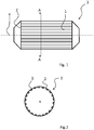
- figure 1 shows a longitudinal cross-section of a horizontal grinding mill 3 having an inner shell 2 comprising a cylindrical wall which the shell 2 comprises lifter bars 1 mounted to the cylindrical wall of the shell 2.
- the grinding mill 3 rotates about its central axis x in a predetermined direction.
- the axis of the shell 2 is horizontally disposed or slightly inclined toward the other end of the shell 2.
- the surface of the inner shell 2 is plated with a lining such as shell plates, wear plates or similar elements for protecting the drum against wear caused by grinding.
- the lining is attached between the lifter bars 1 such that the lifter bars 1 and the lining together protect the surface of the inner shell 2 of the grinding mill 3.
- Figure 2 shows a cross-section of the grinding mill 3 shown in Figure 1 taken along line A-A.
- the grinding mill 3 rotates in a predetermined direction around its axis indicated by x.
- the lifter bars 1 are arranged such that they are mounted to the shell 2 of the grinding mill 3 extending in the longitudinal direction of the horizontally arranged grinding mill.
- the lifter bar 1 comprises a mechanical fixing element, such as channel, a profile or an insert element in the bottom of the lifter bar 1 for mechanically fixing the lifter bar 1 to the shell 2.
- the lifter bar 1 is secured to the shell 2 of the grinding mill 3 with fasteners such as bolts extending from the shell 2 of the grinding mill 3 to the channel, the profile or the insert element in the bottom of the lifter bar 1 securing the lifter bar 1 to the interior wall of the grinding mill 3.
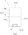
- Figure 3 shows one example of a lifter bar 1 as a cross-sectional view.
- the lifter bar 1 has an outer surface 1a comprising a fixing surface 1b to be arranged against the shell 2 and a wear surface 1c facing toward interior of the grinding mill 3. Part of the wear surface 1c is faced against shell plates arranged next to the lifter bars 1.
- the lifter bar 1 comprises a lifter bar body 10 and a fixing element 11 for connecting the lifter bar 1 to the shell 2 of the grinding mill 3 (the shell and the grinding mill are not shown in the figure).
- the lifter bar body 10 further has an outer surface conforming to the outer surface 1a of the lifter bar 1.
- the lifter bar body 10 further comprises a first portion 10a and a second portion 10b such that the first portion 10a and the second portion 10b form a continuous lifter bar body 10.
- the first portion 10a comprises the fixing element 11 for connecting the lifter bar 10 to the shell 2.
- the fixing element 11 is embedded to the first portion 10a such that it forms part of the fixing surface 1b of the lifter bar 1.
- the fixing element 11 may be a lifter channel connected and embedded to the lifter bar body 10 in the first portion 10a such that the lifter channel forms part of the fixing surface 1b of the lifter bar 1. Through the lifter channel 11 the lifter bar 1 can be mounted to the inner surface of the shell 2 of the grinding mill 3 together with fastening means.
- the lifter bar 1 has length of 0.2 - 3 m and advantageously 0.5 - 1.5 m, width of 1 is 50 - 350 mm and advantageously 100 - 200 mm and height of 100 - 500 mm, advantageously 120 - 300 mm.
- the volume of the lifter bar 1 is 30 - 200 litres, preferably 50-100 litres, most preferably 60-90 litres.
- the second portion of lifter bar which is PU covers 35 - 85% from the total volume of the lifter bar.
- the length defines the reach of the lifter bar 1 when installed to the grinding mill and extending in the longitudinal direction of the horizontally arranged grinding mill
- the width defines the reach of the installed lifter bar 1 along the periphery of the shell of the grinding mill
- the height defines the reach of the lifter bar 1 from the mounting surface of the lifter bar 1 to the opposing end of the lifter bar 1.
- the lifter bar further comprises a reinforced wearing plate 12 attached to the lifter bar body 10 in the area of the second portion 10b such that the wearing plate 12 forms part of the outer surface 1a of the lifter bar 1.
- the reinforced wearing plate 12 comprises a wearing surface 13 for forming part of the outer surface 1a of the lifter bar 1 and an attachment structure 14 provided to the reinforced wearing plate 12 for attaching the reinforced wearing plate 12 to the second portion 10b of the lifter bar body 10.
- the wearing surface 13 is formed as a flat plate-like structure and the attachment structure is a protrusion from the plate-like wearing surface 13.
- the wearing surface 13 has an outer surface 13a and an inner surface 13b.
- the outer surface 13a of the wearing surface 13 forms part of the outer surface of the lifter bar 1 together with the outer surface of the lifter bar body 10.
- the attachment structure 14 is attached to the inner surface 13b of the wearing surface 13 and protrudes from the inner surface 13b of the wearing surface 13 into the lifter bar body 10.
- the length of the attachment structure 14 is at least 1/3 of the width of the lifter bar 1 and said attachment structure is arranged to protrude into the lifter bar body 10 forming a tight connection with the lifter bar body.
- the lifter bar 1 comprises a reinforced wearing plate 12 attached to the lifter bar body 10 in the second portion 10b.
- the reinforced wearing plate 12 comprises metal, said reinforced wearing plate 12 further comprises a wearing surface 13 for forming a part of the outer surface of the lifter bar 1 in a distal end of the second portion 10b or in the vicinity of the second portion 10b.
- An attachment structure 14 is provided to the reinforced wearing plate 12 for attaching the reinforced wearing plate 12 to the lifter bar body 10, said attachment structure 14 protruding into the second portion 10b of the lifter bar body 10 for forming a connection with polyurethane.
- the attachment structure 14 engages mechanically with the lifter bar body 10 and therefore a preferable shape of the attachment structure 14 is annular or round arch like a clamp or a fixing ring comprising a hole 15 arranged to extend through the attachment structure 14.
- the through hole 15 in the attachment structure 14 is arranged in a direction same as the longitudinal direction of the lifter bar 1 when the reinforced wearing plate is connected to the lifter bar body 10 for achieving more durable connection with the lifter bar body 10.
- the attachment structure 14 has a width in the direction of the through hole 0.3 - 5 cm. In other words the attachment structure is made of a material having thickness of 0.3 - 5 cm.
- a plurality of attachment structures 14 are associated with the wearing surface 13 such that the attachment structures 14 are distributed along the length of the wearing surface 13. Both the wearing surface 13 and the attachment structure 14 are made of metal but they may be made of different metal.
- the wearing surface 13 is preferably made of weldable wear-resistant metal.
- the attachment structure 14 is arranged to protrude inside the lifter bar body 10 such that the attachment structure 14 is throughout embedded in the lifter bar body 10.
Landscapes
- Engineering & Computer Science (AREA)
- Food Science & Technology (AREA)
- Mechanical Engineering (AREA)
- Crushing And Grinding (AREA)
- Grinding Of Cylindrical And Plane Surfaces (AREA)
- Cage And Drive Apparatuses For Elevators (AREA)
- Manufacture And Refinement Of Metals (AREA)
- Lift-Guide Devices, And Elevator Ropes And Cables (AREA)
Description
- The invention relates to a lifter bar, and more particularly to a lifter bar as defined in the
independent claim 1. The present invention relates also to a method for making a lifter bar as defined in the independent claim 6, to a method for assembling a lifter bar as defined in the independent claim 9 and to a grinding mill as defined in theclaim 10. - Grinding mills are used for processing hard solid material such that large solid material is grinded into smaller pieces. The lifter bars' function is to assist in lifting the solid material that is being processed in the drum as it rotates.
-
US 5472148 A discloses a lining for a grinding mill assembly, the lining including a plurality of elongate ribs made of a metallic or ceramic material and spacer elements for spacing the ribs from each other circumferentially about the housing, such that the spacer elements and the ribs define a plurality of recesses and each of the recesses are at least partially filled with a rubber or polymeric filler material.FR 2615412 A1 US 4848681 A discloses a lining element for a rotary grinding mill made of elastomeric material, provided on its leading side with respect to rotation with a hard wear layer made of steel, such that the hard wear layer is backed and supported by the elastomeric material of the element. - The lifter bar, the method for making a lifter bar, the method for assembling the lifter bar and the grinding mill are characterized by what is stated in the independent claims. The preferred embodiments are disclosed in the dependent claims.
- The solid material is grinded in a drum shaped shell mounted for rotation about its central axis in the grinding mill. The axis of the rotatable shell is generally horizontally arranged or slightly inclined towards one end in the grinding mill. The interior of the shell forms a treatment chamber and has a cylindrical wall. The inner surface of the chamber is plated with shell plates for protecting the shell because the material to be processed is fed to the treatment chamber and grinding it causes wear in the chamber. The interior wall of the shell is equipped with lifter bars for lifting the material inside the shell along the rotation so that as the shell rotates the lifter bars lift up the solid material along the inside wall of the shell to a point where gravity causes the solid material to fall down inside the shell and by falling down the solid material is crushed. A line of lifter bars extend from one end of the drum to another and they are arranged in a short spacing adjacently along the cylindrical wall of the shell such that there are shell plates arranged between adjacent lifter bars. As compared to the shell plates the lifter bars protrude more from the shell wall than the shell plates.
- The lifter bar has a volume which is 30 - 200 litres, advantageously 50-100 litres. The lifter bar has an outer surface comprising a fixing surface to be arranged against the shell and a wear surface facing toward interior of the grinding mill. The lifter bar comprises a lifter bar body having an outer surface conforming the outer surface of the lifter bar and a fixing element for connecting the lifter bar to the shell of the grinding mill. The fixing element is a mechanical fixing element, for example a lifter channel or holes in the lifter bar such that bolts can be arranged through the holes and through the shell of the grinding mill to fasten the lifter bar to the shell.
- The lifter bar body comprises a first portion and a second portion forming a continuous lifter bar body, said first portion comprises the fixing element for connecting the lifter bar to the shell. The fixing element is embedded to the first portion such that it forms part of the fixing surface of the lifter bar. The fixing surface is to be arranged against the shell and the lifter bar is to be secured to the shell through the fixing element in the lifter bar when installed. An example of the fixing element for connecting the lifter bar to the shell is a lifter channel which is connected to the first portion of the lifter bar body and embedded therein such that it forms part of the fixing surface of the lifter bar body. The lifter bars are mechanically fastened to the inner surface of the shell with fastening means such as a bolt connection through the fixing element which is for example a lifter channel. When the lifter bar is installed to the shell of the grinding mill the fixing surface of the lifter bar body is faced against the inner surface of the shell of the grinding mill. The fixing element is typically made of metal and for example of aluminium, but it could be made of any other metal as well, for example steel. The second portion of the lifter bar body is made of polyurethane and forms 35 - 85 % of the volume of the lifter bar.
- The polyurethane in the context of this application means polyurethane material that may comprise additives, such as metal particles, ceramics or carbide. The polyurethane material comprises at least 50% and preferably at least 80% pure polyurethane the rest being additives and possible impurities.
- The first portion of the lifter bar body may be made of rubber. Alternatively the first portion of the lifter bar body may be made of other polyurethane than the polyurethane in the second portion of the lifter bar body.
- The first portion of the lifter bar body may be recycled.
- The polyurethane in the second portion of the lifter bar body may be more wear resistant than the polyurethane in the first portion of the lifter bar body. The polyurethane in the second portion and the polyurethane in the first portion may have a difference in wear resistance which is at least 10 %, such that the polyurethane in the second portion is more wear resistant than the polyurethane in the first portion.
- In the method for making the lifter bar as describe earlier, the method comprises the steps of providing a mould for moulding the lifter bar, adding polyurethane into the mould for forming the second portion of the lifter bar body, which the polyurethane is in such a state that it is arranged to react in the mould an form a connection with a material of the first portion of the lifter bar body and adding other material than the polyurethane of the second portion into the mould for forming the first portion of the lifter bar body. The material of the first portion is in such a state that it is arranged to react in the mould such that the polyurethane in the second portion and the material in the first portion form a connection with each other for forming a continuous lifter bar body.
- In one embodiment the method for making the lifter bar may further comprise providing a reinforced wearing plate comprising a wearing surface and an attachment structure for mechanically engaging with the second portion of the lifter bar body. The method may also comprise arranging the reinforced wearing plate in the mould such that the wearing surface forms at least part of the outer surface of the moulded lifter bar.
- In one embodiment the method for making the lifter bar further comprises a step of providing a mould comprises providing a mould made of sheet metal having a thickness of less than 10mm, preferably less than 5mm and most preferably 0.2-2mm.
- In the method for assembling the lifter bar as described earlier to a shell of a grinding mill, the method comprises the steps of attaching the lifter bar to the shell of the grinding mill by arranging the fixing element against the shell and fastening the lifter bar to the shell with fastening means through the fixing element.
- A grinding mill comprising multiple lifter bars as described earlier are arranged to a shell of the grinding mill. The lifter bar is used in grinding mills for ore grinding which the grinding mill's grinding energy per ton of ore is 1 -30 kWh/t and preferably 3-20 kWh/t. The diameter of the grinding mill is 1 - 15 m, and most typically 1.5 - 10 m. The length of the grinding mill in horizontal direction is between 1 and 15 meter, and most typically from 2 to 8 m. Thickness of the shell of the grinding mill is 0.5 - 10 cm.This kind of grinding mill is shown in
figures 1 and 2 . Grinding mills can be for example SAG mills, AG mills, Ball mills, rod mills, scrubbers or regrinds. - In one embodiment the grinding mill may be arranged to grind input material of which at least 80% has particle size between 0.1-300mm, preferably 1-250mm and most preferably 80-220mm to grinded output material of which 80% has particle size between 0.02-3mm, preferably 0.05-2.5mm and most preferably 0.2-2mm.
- The grinding mill may further comprise shell plates arranged between adjacent lifter bars.
- In one embodiment a lifter bar is provided having a lifter bar body which comprises 35 - 85 % polyurethane of the volume of the lifter bar.
- In one embodiment the second portion of the lifter bar comprises polyurethane 40 - 80 % of the volume of the lifter bar.
- Lifter bars can be made with moulds made of sheet metal having a thickness of less than 10mm, preferably less than 5mm and most preferably 0.2-2mm.
- Effect of a lifter bar comprising 35 - 85% polyurethane from the total volume of the lifter bar is that there is low energy consumption when manufacturing lifter bars and moulds which are used for manufacturing the lifter bars are lighter. Effect of that the second portion of lifter bar which is PU, covers 35 - 85% from the total volume of the lifter bar, is that there is low energy consumption when manufacturing lifter bars which fit well between the shell plates, and moulds which are used for manufacturing the lifter bars are lighter.
- In the following the lifter bar will be described in greater detail by means of preferred embodiments with reference to the attached drawings, in which
-
Figure 1 shows a grinding mill; -
Figure 2 shows a cross section of the grinding mill infigure 1 ; -
Figure 3 shows a lifter bar; and -
Figure 4 shows an embodiment according to a lifter bar shown infigure 3 . -
Figure 1 shows, as already described earlier, that the solid material is grinded in a drum shaped shell 2 mounted for rotation about its central axis in thegrinding mill 3. The axis of the rotatable shell 2 is generally horizontally arranged or slightly inclined towards one end in the grindingmill 3. The interior of the shell 2 forms a treatment chamber and has a cylindrical wall. The inner surface of the chamber is plated with shell plates for protecting the shell 2 because the material to be processed is fed to the treatment chamber and grinding it causes wear in the chamber. The interior wall of the shell 2 is equipped withlifter bars 1 for lifting the material inside the shell 2 along the rotation so that as the shell 2 rotates the lifter bars 1 lift up the solid material along the inside wall of the shell 2 to a point where gravity causes the solid material to fall down inside the shell 2 and by falling down the solid material is crushed. A line oflifter 1 bars extend from one end of the drum to another and they are arranged in a short spacing adjacently along the cylindrical wall of the shell 2 such that there are shell plates arranged between adjacent lifter bars 1. As compared to the shell plates the lifter bars 1 protrude more from the shell 2 wall than the shell plates. - In other words
figure 1 shows a longitudinal cross-section of ahorizontal grinding mill 3 having an inner shell 2 comprising a cylindrical wall which the shell 2 comprises lifter bars 1 mounted to the cylindrical wall of the shell 2. The grindingmill 3 rotates about its central axis x in a predetermined direction. The axis of the shell 2 is horizontally disposed or slightly inclined toward the other end of the shell 2. The surface of the inner shell 2 is plated with a lining such as shell plates, wear plates or similar elements for protecting the drum against wear caused by grinding. The lining is attached between the lifter bars 1 such that the lifter bars 1 and the lining together protect the surface of the inner shell 2 of the grindingmill 3. -
Figure 2 shows a cross-section of the grindingmill 3 shown inFigure 1 taken along line A-A. The grindingmill 3 rotates in a predetermined direction around its axis indicated by x. The lifter bars 1 are arranged such that they are mounted to the shell 2 of the grindingmill 3 extending in the longitudinal direction of the horizontally arranged grinding mill. Thelifter bar 1 comprises a mechanical fixing element, such as channel, a profile or an insert element in the bottom of thelifter bar 1 for mechanically fixing thelifter bar 1 to the shell 2. Thelifter bar 1 is secured to the shell 2 of the grindingmill 3 with fasteners such as bolts extending from the shell 2 of the grindingmill 3 to the channel, the profile or the insert element in the bottom of thelifter bar 1 securing thelifter bar 1 to the interior wall of the grindingmill 3. -
Figure 3 shows one example of alifter bar 1 as a cross-sectional view. Thelifter bar 1 has anouter surface 1a comprising a fixingsurface 1b to be arranged against the shell 2 and awear surface 1c facing toward interior of the grindingmill 3. Part of thewear surface 1c is faced against shell plates arranged next to the lifter bars 1. Thelifter bar 1 comprises alifter bar body 10 and a fixingelement 11 for connecting thelifter bar 1 to the shell 2 of the grinding mill 3 (the shell and the grinding mill are not shown in the figure). Thelifter bar body 10 further has an outer surface conforming to theouter surface 1a of thelifter bar 1. Thelifter bar body 10 further comprises afirst portion 10a and asecond portion 10b such that thefirst portion 10a and thesecond portion 10b form a continuouslifter bar body 10. Thefirst portion 10a comprises the fixingelement 11 for connecting thelifter bar 10 to the shell 2. The fixingelement 11 is embedded to thefirst portion 10a such that it forms part of the fixingsurface 1b of thelifter bar 1. - The fixing
element 11 may be a lifter channel connected and embedded to thelifter bar body 10 in thefirst portion 10a such that the lifter channel forms part of the fixingsurface 1b of thelifter bar 1. Through thelifter channel 11 thelifter bar 1 can be mounted to the inner surface of the shell 2 of the grindingmill 3 together with fastening means. - The
lifter bar 1 has length of 0.2 - 3 m and advantageously 0.5 - 1.5 m, width of 1 is 50 - 350 mm and advantageously 100 - 200 mm and height of 100 - 500 mm, advantageously 120 - 300 mm. The volume of thelifter bar 1 is 30 - 200 litres, preferably 50-100 litres, most preferably 60-90 litres. The second portion of lifter bar which is PU, covers 35 - 85% from the total volume of the lifter bar. Dimensions in thelifter bar 1 are such that the length defines the reach of thelifter bar 1 when installed to the grinding mill and extending in the longitudinal direction of the horizontally arranged grinding mill, the width defines the reach of the installedlifter bar 1 along the periphery of the shell of the grinding mill and the height defines the reach of thelifter bar 1 from the mounting surface of thelifter bar 1 to the opposing end of thelifter bar 1. - In an embodiment of the lifter bar shown in
figure 4 the lifter bar further comprises a reinforced wearingplate 12 attached to thelifter bar body 10 in the area of thesecond portion 10b such that the wearingplate 12 forms part of theouter surface 1a of thelifter bar 1. The reinforced wearingplate 12 comprises a wearingsurface 13 for forming part of theouter surface 1a of thelifter bar 1 and anattachment structure 14 provided to the reinforced wearingplate 12 for attaching the reinforced wearingplate 12 to thesecond portion 10b of thelifter bar body 10. The wearingsurface 13 is formed as a flat plate-like structure and the attachment structure is a protrusion from the plate-like wearingsurface 13. The wearingsurface 13 has anouter surface 13a and aninner surface 13b. Theouter surface 13a of the wearingsurface 13 forms part of the outer surface of thelifter bar 1 together with the outer surface of thelifter bar body 10. Theattachment structure 14 is attached to theinner surface 13b of the wearingsurface 13 and protrudes from theinner surface 13b of the wearingsurface 13 into thelifter bar body 10. The length of theattachment structure 14 is at least 1/3 of the width of thelifter bar 1 and said attachment structure is arranged to protrude into thelifter bar body 10 forming a tight connection with the lifter bar body. - In one embodiment the
lifter bar 1 comprises a reinforced wearingplate 12 attached to thelifter bar body 10 in thesecond portion 10b. The reinforced wearingplate 12 comprises metal, said reinforced wearingplate 12 further comprises a wearingsurface 13 for forming a part of the outer surface of thelifter bar 1 in a distal end of thesecond portion 10b or in the vicinity of thesecond portion 10b. Anattachment structure 14 is provided to the reinforced wearingplate 12 for attaching the reinforced wearingplate 12 to thelifter bar body 10, saidattachment structure 14 protruding into thesecond portion 10b of thelifter bar body 10 for forming a connection with polyurethane. - The
attachment structure 14 engages mechanically with thelifter bar body 10 and therefore a preferable shape of theattachment structure 14 is annular or round arch like a clamp or a fixing ring comprising ahole 15 arranged to extend through theattachment structure 14. The throughhole 15 in theattachment structure 14 is arranged in a direction same as the longitudinal direction of thelifter bar 1 when the reinforced wearing plate is connected to thelifter bar body 10 for achieving more durable connection with thelifter bar body 10. Theattachment structure 14 has a width in the direction of the through hole 0.3 - 5 cm. In other words the attachment structure is made of a material having thickness of 0.3 - 5 cm. A plurality ofattachment structures 14 are associated with the wearingsurface 13 such that theattachment structures 14 are distributed along the length of the wearingsurface 13. Both the wearingsurface 13 and theattachment structure 14 are made of metal but they may be made of different metal. The wearingsurface 13 is preferably made of weldable wear-resistant metal. - In one embodiment the
attachment structure 14 is arranged to protrude inside thelifter bar body 10 such that theattachment structure 14 is throughout embedded in thelifter bar body 10. - It will be obvious to a person skilled in the art that, as the technology advances, the inventive concept can be implemented in various ways. The invention and its embodiments are not limited to the examples described above but may vary within the scope of the claims.
Claims (14)
- A lifter bar (1) mountable to a shell (2) of a grinding mill (3) for ore grinding, said lifter bar (1) having a volume, said lifter bar (1) further having an outer surface (1a) comprising a fixing surface (1b) to be arranged against the shell (2) and a wear surface (1c) facing toward interior of the grinding mill (3), the lifter bar (1) comprises
a lifter bar body (10) having an outer surface conforming the outer surface (1a) of the lifter bar (1), and
a fixing element (11) for connecting the lifter bar (1) to the shell (2) of the grinding mill (3), characterized in that
the lifter bar body (10) further comprises a first portion (10a) and a second portion (10b) forming a continuous lifter bar body (10),
the fixing element is embedded to the first portion (10a) such that it forms part of the fixing surface (1b) of the lifter bar (1), said first portion (10a) of the lifter bar body (10) is made of rubber,
the second portion (10b) is made of polyurethane and forming 35 - 85 % of the volume of the lifter bar (1). - A lifter bar (1) according to claim 1, characterized in that the second portion (10b) comprises polyurethane 40 - 80 % of the volume of the lifter bar (1).
- A lifter bar (1) according to any preceding claims, character - ized in that the lifter bar (1) further comprises a reinforced wearing plate (12) attached to the lifter bar body (10) in the second portion (10b), the reinforced wearing plate (12) comprises metal, said reinforced wearing plate (12) further comprises a wearing surface (13) for forming a part of the outer surface of the lifter bar (1) in a distal end of the second portion (10b) or in the vicinity of the second portion (10b); and an attachment structure (14) provided to the reinforced wearing plate (12) for attaching the reinforced wearing plate (12) to the lifter bar body (10), said attachment structure (14) protruding into the second portion (10b) of the lifter bar body (10) for forming a connection with polyurethane.
- A lifter bar (1) according to any preceding claims, character - ized in that fixing element (11) is a mechanical fixing element.
- A lifter bar (1) according to any preceding claims, character - ized in that fixing element (11) is a lifter channel (11).
- Method for making a lifter bar (1) according to claim 1, the method comprising the steps of:providing a mould for moulding the lifter bar (1);adding polyurethane into the mould for forming the second portion (10b) of the lifter bar body (10), the polyurethane is in such a state that it is arranged to react in the mould an form a connection with a material of the first portion (10a) of the lifter bar body (10); andadding rubber into the mould for forming the first portion (10a) of the lifter bar body (10), the rubber is in such a state that it is arranged to react in the mould such that the polyurethane in the second portion (10b) and the rubber in the first portion (10a) form a connection with each other for forming a continuous lifter bar body (10).
- Method according to claim 6, characterized in that the method further comprises the steps of:providing a reinforced wearing plate (12) comprising a wearing surface (12a) and an attachment structure (12b) for mechanically engaging with the second portion (10b) of the lifter bar body (10); andarranging the reinforced wearing plate (12) in the mould such that the wearing surface (12a) forms at least part of the outer surface of the moulded lifter bar (1).
- Method according to claim 6 or 7, characterized in that the step of providing a mould comprises providing a mould made of sheet metal having a thickness of less than 10mm, preferably less than 5mm and most preferably 0.2-2mm.
- Method for assembling a lifter bar (1) according to claim 1 to a shell (2) of a grinding mill (3), the method comprising the steps of:attaching the lifter bar (1) to the shell (2) of the grinding mill (3) by arranging the fixing element (11) against the shell (2); andfastening the lifter bar (1) to the shell (2) with fastening means through the fixing element (11).
- A grinding mill (3) comprising multiple lifter bars (1) arranged to a shell (2) of the grinding mill (3), said lifter bars (1) are according to claim 1.
- A grinding mill (3) according to claim 10, characterized in that the grinding energy per ton of ore of the grinding mill (3) is 1 -30 kWh/t and preferably 3-20 kWh/t.
- A grinding mill (3) according to any of claims 10 - 11, charac- terized in that the shell (2) of the grinding mill (3) having a thickness of 0.5 - 10cm.
- A grinding mill (3) according to any of claims 10 - 12, charac- terized in that said grinding mill (3) is arranged to grind input material of which at least 80% has particle size between 0.1-300mm, preferably 1-250mm and most preferably 80-220mm to grinded output material of which 80% has particle size between 0.02-3mm, preferably 0.05-2.5mm and most preferably 0.2-2mm.
- A grinding mill (3) according to any of claims 10 - 13, charac- terized in that the grinding mill (3) further comprises shell plates arranged between adjacent lifter bars (1).
Applications Claiming Priority (2)
| Application Number | Priority Date | Filing Date | Title |
|---|---|---|---|
| FI20145901A FI20145901A (en) | 2014-10-14 | 2014-10-14 | Lifting beam, method of making a lifting beam, method of assembling a lifting beam and mill |
| PCT/FI2015/050685 WO2016059294A1 (en) | 2014-10-14 | 2015-10-12 | Lifter bar, method for making a lifter bar, method for assembling a lifter bar and a grinding mill |
Publications (2)
| Publication Number | Publication Date |
|---|---|
| EP3206799A1 EP3206799A1 (en) | 2017-08-23 |
| EP3206799B1 true EP3206799B1 (en) | 2021-04-28 |
Family
ID=54365289
Family Applications (1)
| Application Number | Title | Priority Date | Filing Date |
|---|---|---|---|
| EP15787647.5A Active EP3206799B1 (en) | 2014-10-14 | 2015-10-12 | Lifter bar, method for making a lifter bar, method for assembling a lifter bar and a grinding mill |
Country Status (13)
| Country | Link |
|---|---|
| US (1) | US10166547B2 (en) |
| EP (1) | EP3206799B1 (en) |
| CN (1) | CN106794467B (en) |
| AU (1) | AU2015332294B2 (en) |
| CA (1) | CA2964329C (en) |
| CL (1) | CL2017000904A1 (en) |
| EA (1) | EA032079B9 (en) |
| ES (1) | ES2880933T3 (en) |
| FI (1) | FI20145901A (en) |
| MX (1) | MX2017004586A (en) |
| PE (1) | PE20171062A1 (en) |
| PT (1) | PT3206799T (en) |
| WO (1) | WO2016059294A1 (en) |
Families Citing this family (1)
| Publication number | Priority date | Publication date | Assignee | Title |
|---|---|---|---|---|
| CN111545117B (en) * | 2020-05-14 | 2022-06-10 | 禹州市新佳汇新材料科技有限公司 | Titanium-silicon alloy material and preparation system and method thereof |
Family Cites Families (22)
| Publication number | Priority date | Publication date | Assignee | Title |
|---|---|---|---|---|
| NL275126A (en) * | 1961-02-25 | |||
| US3295772A (en) * | 1964-12-22 | 1967-01-03 | Us Stoneware Inc | Ball mill or the like |
| US3783918A (en) * | 1972-02-16 | 1974-01-08 | Chicago Bridge & Iron Co | Rotating drum with elastomeric pad-mounted supporting rings |
| SE421508B (en) * | 1979-11-06 | 1982-01-04 | Trelleborg Ab | WASTE GUM PRODUCT AND WAY TO MANUFACTURE IT |
| US4580734A (en) * | 1984-07-02 | 1986-04-08 | The B. F. Goodrich Company | Rotary pulverizers/ball mills |
| FR2615412A1 (en) * | 1987-05-22 | 1988-11-25 | Magotteaux Sa | COMPOSITE WEAR FOR HORIZONTAL SHREDDERS |
| CA1301731C (en) * | 1987-06-02 | 1992-05-26 | Klas-Goran Eriksson | Wear resistant element |
| AU654608B2 (en) * | 1992-01-10 | 1994-11-10 | Envirotech Pumpsystems, Inc. | Grinding mill, lining and associated method of manufacture |
| SE468627B (en) * | 1992-02-14 | 1993-02-22 | Harald Kenneth Lejonklou | WEAR ELEMENT |
| CA2158831A1 (en) * | 1994-10-03 | 1996-04-04 | Michael Wason | Grinding mill liner adapter |
| SE9800624L (en) * | 1998-02-27 | 1998-12-21 | Svedala Trellex Ab | Exposed to abrasion and abrasive lining elements and fasteners for forming such a wall |
| US20030062372A1 (en) * | 2001-10-02 | 2003-04-03 | Metso Minerals (Trelleborg) Ab | Wear-resistant lining element and wear lining made thereof |
| CN2579519Y (en) * | 2002-11-18 | 2003-10-15 | 株洲市工业橡胶制品厂 | Mill tubular part rubber lining structure |
| SE528692C2 (en) * | 2005-04-01 | 2007-01-23 | Sandvik Intellectual Property | A wear-resistant and noise-reducing device |
| SE528679C2 (en) * | 2005-06-07 | 2007-01-23 | Metso Minerals Wear Prot Ab | Wear lining elements and wear lining |
| SE531347C2 (en) * | 2007-07-10 | 2009-03-03 | Metso Minerals Wear Prot Ab | Wear lining elements and device for attaching such |
| EA024432B1 (en) * | 2008-08-11 | 2016-09-30 | Уиэр Минералз Острейлиа Лтд. | Liner component for a grinding mill and method of fabricating the component |
| WO2011037600A1 (en) * | 2009-09-25 | 2011-03-31 | Weir Slurry Group, Inc. | Mill liner for a grinding mill |
| CN202490657U (en) * | 2012-04-10 | 2012-10-17 | 湖北司克嘉耐磨橡胶制品有限公司 | Rubber lining plate lifting strip of ball grinding mill |
| CN202983797U (en) * | 2012-12-25 | 2013-06-12 | 莱州市精诚橡胶有限公司 | Steel glue lifting bar for composite liner plate |
| CN203408762U (en) * | 2013-07-30 | 2014-01-29 | 江苏恒业机械有限公司 | Split lining plate lifting bar assembly |
| CN104056698A (en) * | 2014-06-27 | 2014-09-24 | 江西耐普矿机新材料股份有限公司 | Wear-resisting semi-autogenous mill composite lining plate |
-
2014
- 2014-10-14 FI FI20145901A patent/FI20145901A/en not_active Application Discontinuation
-
2015
- 2015-10-12 WO PCT/FI2015/050685 patent/WO2016059294A1/en not_active Ceased
- 2015-10-12 US US15/517,696 patent/US10166547B2/en active Active
- 2015-10-12 AU AU2015332294A patent/AU2015332294B2/en not_active Ceased
- 2015-10-12 CN CN201580055250.8A patent/CN106794467B/en active Active
- 2015-10-12 MX MX2017004586A patent/MX2017004586A/en unknown
- 2015-10-12 PT PT157876475T patent/PT3206799T/en unknown
- 2015-10-12 EA EA201790711A patent/EA032079B9/en not_active IP Right Cessation
- 2015-10-12 ES ES15787647T patent/ES2880933T3/en active Active
- 2015-10-12 CA CA2964329A patent/CA2964329C/en active Active
- 2015-10-12 PE PE2017000595A patent/PE20171062A1/en unknown
- 2015-10-12 EP EP15787647.5A patent/EP3206799B1/en active Active
-
2017
- 2017-04-12 CL CL2017000904A patent/CL2017000904A1/en unknown
Non-Patent Citations (1)
| Title |
|---|
| None * |
Also Published As
| Publication number | Publication date |
|---|---|
| EA032079B1 (en) | 2019-04-30 |
| CN106794467B (en) | 2020-01-31 |
| US20170304836A1 (en) | 2017-10-26 |
| AU2015332294A1 (en) | 2017-05-18 |
| PE20171062A1 (en) | 2017-07-21 |
| WO2016059294A1 (en) | 2016-04-21 |
| EP3206799A1 (en) | 2017-08-23 |
| ES2880933T3 (en) | 2021-11-26 |
| EA032079B9 (en) | 2019-05-31 |
| CA2964329A1 (en) | 2016-04-21 |
| FI20145901A7 (en) | 2016-04-15 |
| US10166547B2 (en) | 2019-01-01 |
| CN106794467A (en) | 2017-05-31 |
| PT3206799T (en) | 2021-07-30 |
| MX2017004586A (en) | 2017-10-12 |
| EA201790711A1 (en) | 2017-10-31 |
| CA2964329C (en) | 2023-03-14 |
| FI20145901A (en) | 2016-04-15 |
| AU2015332294B2 (en) | 2019-01-24 |
| CL2017000904A1 (en) | 2017-10-30 |
Similar Documents
| Publication | Publication Date | Title |
|---|---|---|
| EP1838446B1 (en) | Mill liner assembly | |
| US8235318B2 (en) | Mill liner for a grinding mill | |
| US10967385B2 (en) | Method for making a shell plate | |
| DK2825316T3 (en) | Press roller | |
| WO2012012880A1 (en) | Wear-resistant liner assembly | |
| EP3206798B1 (en) | A lifter bar, method for making a lifter bar, method for assembling a lifter bar and a grinding mill | |
| US10166547B2 (en) | Lifter bar, method for making a lifter bar, method for assembling a lifter bar and a grinding mill | |
| EP2986389B1 (en) | A method of making a lifter bar, a refurbished lifter bar and a mould | |
| US20160250646A1 (en) | Treaded lifter bar | |
| AU2010298710B8 (en) | Mill liner for a grinding mill | |
| AU2013204268B2 (en) | Mill liner for a grinding mill |
Legal Events
| Date | Code | Title | Description |
|---|---|---|---|
| STAA | Information on the status of an ep patent application or granted ep patent |
Free format text: STATUS: THE INTERNATIONAL PUBLICATION HAS BEEN MADE |
|
| PUAI | Public reference made under article 153(3) epc to a published international application that has entered the european phase |
Free format text: ORIGINAL CODE: 0009012 |
|
| STAA | Information on the status of an ep patent application or granted ep patent |
Free format text: STATUS: REQUEST FOR EXAMINATION WAS MADE |
|
| 17P | Request for examination filed |
Effective date: 20170512 |
|
| AK | Designated contracting states |
Kind code of ref document: A1 Designated state(s): AL AT BE BG CH CY CZ DE DK EE ES FI FR GB GR HR HU IE IS IT LI LT LU LV MC MK MT NL NO PL PT RO RS SE SI SK SM TR |
|
| AX | Request for extension of the european patent |
Extension state: BA ME |
|
| DAV | Request for validation of the european patent (deleted) | ||
| DAX | Request for extension of the european patent (deleted) | ||
| STAA | Information on the status of an ep patent application or granted ep patent |
Free format text: STATUS: EXAMINATION IS IN PROGRESS |
|
| 17Q | First examination report despatched |
Effective date: 20180307 |
|
| GRAP | Despatch of communication of intention to grant a patent |
Free format text: ORIGINAL CODE: EPIDOSNIGR1 |
|
| STAA | Information on the status of an ep patent application or granted ep patent |
Free format text: STATUS: GRANT OF PATENT IS INTENDED |
|
| INTG | Intention to grant announced |
Effective date: 20201125 |
|
| GRAS | Grant fee paid |
Free format text: ORIGINAL CODE: EPIDOSNIGR3 |
|
| GRAA | (expected) grant |
Free format text: ORIGINAL CODE: 0009210 |
|
| STAA | Information on the status of an ep patent application or granted ep patent |
Free format text: STATUS: THE PATENT HAS BEEN GRANTED |
|
| RAP1 | Party data changed (applicant data changed or rights of an application transferred) |
Owner name: METSO OUTOTEC FINLAND OY |
|
| AK | Designated contracting states |
Kind code of ref document: B1 Designated state(s): AL AT BE BG CH CY CZ DE DK EE ES FI FR GB GR HR HU IE IS IT LI LT LU LV MC MK MT NL NO PL PT RO RS SE SI SK SM TR |
|
| REG | Reference to a national code |
Ref country code: GB Ref legal event code: FG4D |
|
| REG | Reference to a national code |
Ref country code: CH Ref legal event code: EP |
|
| REG | Reference to a national code |
Ref country code: AT Ref legal event code: REF Ref document number: 1386506 Country of ref document: AT Kind code of ref document: T Effective date: 20210515 |
|
| REG | Reference to a national code |
Ref country code: DE Ref legal event code: R096 Ref document number: 602015068712 Country of ref document: DE |
|
| REG | Reference to a national code |
Ref country code: IE Ref legal event code: FG4D |
|
| REG | Reference to a national code |
Ref country code: FI Ref legal event code: FGE |
|
| REG | Reference to a national code |
Ref country code: PT Ref legal event code: SC4A Ref document number: 3206799 Country of ref document: PT Date of ref document: 20210730 Kind code of ref document: T Free format text: AVAILABILITY OF NATIONAL TRANSLATION Effective date: 20210726 |
|
| REG | Reference to a national code |
Ref country code: SE Ref legal event code: TRGR |
|
| REG | Reference to a national code |
Ref country code: LT Ref legal event code: MG9D |
|
| REG | Reference to a national code |
Ref country code: AT Ref legal event code: MK05 Ref document number: 1386506 Country of ref document: AT Kind code of ref document: T Effective date: 20210428 |
|
| PG25 | Lapsed in a contracting state [announced via postgrant information from national office to epo] |
Ref country code: NL Free format text: LAPSE BECAUSE OF FAILURE TO SUBMIT A TRANSLATION OF THE DESCRIPTION OR TO PAY THE FEE WITHIN THE PRESCRIBED TIME-LIMIT Effective date: 20210428 Ref country code: LT Free format text: LAPSE BECAUSE OF FAILURE TO SUBMIT A TRANSLATION OF THE DESCRIPTION OR TO PAY THE FEE WITHIN THE PRESCRIBED TIME-LIMIT Effective date: 20210428 Ref country code: AT Free format text: LAPSE BECAUSE OF FAILURE TO SUBMIT A TRANSLATION OF THE DESCRIPTION OR TO PAY THE FEE WITHIN THE PRESCRIBED TIME-LIMIT Effective date: 20210428 Ref country code: HR Free format text: LAPSE BECAUSE OF FAILURE TO SUBMIT A TRANSLATION OF THE DESCRIPTION OR TO PAY THE FEE WITHIN THE PRESCRIBED TIME-LIMIT Effective date: 20210428 |
|
| REG | Reference to a national code |
Ref country code: ES Ref legal event code: FG2A Ref document number: 2880933 Country of ref document: ES Kind code of ref document: T3 Effective date: 20211126 |
|
| PG25 | Lapsed in a contracting state [announced via postgrant information from national office to epo] |
Ref country code: RS Free format text: LAPSE BECAUSE OF FAILURE TO SUBMIT A TRANSLATION OF THE DESCRIPTION OR TO PAY THE FEE WITHIN THE PRESCRIBED TIME-LIMIT Effective date: 20210428 Ref country code: NO Free format text: LAPSE BECAUSE OF FAILURE TO SUBMIT A TRANSLATION OF THE DESCRIPTION OR TO PAY THE FEE WITHIN THE PRESCRIBED TIME-LIMIT Effective date: 20210728 Ref country code: PL Free format text: LAPSE BECAUSE OF FAILURE TO SUBMIT A TRANSLATION OF THE DESCRIPTION OR TO PAY THE FEE WITHIN THE PRESCRIBED TIME-LIMIT Effective date: 20210428 Ref country code: GR Free format text: LAPSE BECAUSE OF FAILURE TO SUBMIT A TRANSLATION OF THE DESCRIPTION OR TO PAY THE FEE WITHIN THE PRESCRIBED TIME-LIMIT Effective date: 20210729 Ref country code: LV Free format text: LAPSE BECAUSE OF FAILURE TO SUBMIT A TRANSLATION OF THE DESCRIPTION OR TO PAY THE FEE WITHIN THE PRESCRIBED TIME-LIMIT Effective date: 20210428 Ref country code: IS Free format text: LAPSE BECAUSE OF FAILURE TO SUBMIT A TRANSLATION OF THE DESCRIPTION OR TO PAY THE FEE WITHIN THE PRESCRIBED TIME-LIMIT Effective date: 20210828 |
|
| REG | Reference to a national code |
Ref country code: NL Ref legal event code: MP Effective date: 20210428 |
|
| PG25 | Lapsed in a contracting state [announced via postgrant information from national office to epo] |
Ref country code: RO Free format text: LAPSE BECAUSE OF FAILURE TO SUBMIT A TRANSLATION OF THE DESCRIPTION OR TO PAY THE FEE WITHIN THE PRESCRIBED TIME-LIMIT Effective date: 20210428 Ref country code: SK Free format text: LAPSE BECAUSE OF FAILURE TO SUBMIT A TRANSLATION OF THE DESCRIPTION OR TO PAY THE FEE WITHIN THE PRESCRIBED TIME-LIMIT Effective date: 20210428 Ref country code: SM Free format text: LAPSE BECAUSE OF FAILURE TO SUBMIT A TRANSLATION OF THE DESCRIPTION OR TO PAY THE FEE WITHIN THE PRESCRIBED TIME-LIMIT Effective date: 20210428 Ref country code: EE Free format text: LAPSE BECAUSE OF FAILURE TO SUBMIT A TRANSLATION OF THE DESCRIPTION OR TO PAY THE FEE WITHIN THE PRESCRIBED TIME-LIMIT Effective date: 20210428 Ref country code: DK Free format text: LAPSE BECAUSE OF FAILURE TO SUBMIT A TRANSLATION OF THE DESCRIPTION OR TO PAY THE FEE WITHIN THE PRESCRIBED TIME-LIMIT Effective date: 20210428 Ref country code: CZ Free format text: LAPSE BECAUSE OF FAILURE TO SUBMIT A TRANSLATION OF THE DESCRIPTION OR TO PAY THE FEE WITHIN THE PRESCRIBED TIME-LIMIT Effective date: 20210428 |
|
| REG | Reference to a national code |
Ref country code: DE Ref legal event code: R097 Ref document number: 602015068712 Country of ref document: DE |
|
| PLBE | No opposition filed within time limit |
Free format text: ORIGINAL CODE: 0009261 |
|
| STAA | Information on the status of an ep patent application or granted ep patent |
Free format text: STATUS: NO OPPOSITION FILED WITHIN TIME LIMIT |
|
| 26N | No opposition filed |
Effective date: 20220131 |
|
| REG | Reference to a national code |
Ref country code: CH Ref legal event code: PL |
|
| PG25 | Lapsed in a contracting state [announced via postgrant information from national office to epo] |
Ref country code: IS Free format text: LAPSE BECAUSE OF FAILURE TO SUBMIT A TRANSLATION OF THE DESCRIPTION OR TO PAY THE FEE WITHIN THE PRESCRIBED TIME-LIMIT Effective date: 20210828 Ref country code: AL Free format text: LAPSE BECAUSE OF FAILURE TO SUBMIT A TRANSLATION OF THE DESCRIPTION OR TO PAY THE FEE WITHIN THE PRESCRIBED TIME-LIMIT Effective date: 20210428 |
|
| REG | Reference to a national code |
Ref country code: BE Ref legal event code: MM Effective date: 20211031 |
|
| GBPC | Gb: european patent ceased through non-payment of renewal fee |
Effective date: 20211012 |
|
| PG25 | Lapsed in a contracting state [announced via postgrant information from national office to epo] |
Ref country code: MC Free format text: LAPSE BECAUSE OF FAILURE TO SUBMIT A TRANSLATION OF THE DESCRIPTION OR TO PAY THE FEE WITHIN THE PRESCRIBED TIME-LIMIT Effective date: 20210428 |
|
| PG25 | Lapsed in a contracting state [announced via postgrant information from national office to epo] |
Ref country code: LU Free format text: LAPSE BECAUSE OF NON-PAYMENT OF DUE FEES Effective date: 20211012 Ref country code: IT Free format text: LAPSE BECAUSE OF FAILURE TO SUBMIT A TRANSLATION OF THE DESCRIPTION OR TO PAY THE FEE WITHIN THE PRESCRIBED TIME-LIMIT Effective date: 20210428 Ref country code: GB Free format text: LAPSE BECAUSE OF NON-PAYMENT OF DUE FEES Effective date: 20211012 Ref country code: BE Free format text: LAPSE BECAUSE OF NON-PAYMENT OF DUE FEES Effective date: 20211031 |
|
| PG25 | Lapsed in a contracting state [announced via postgrant information from national office to epo] |
Ref country code: LI Free format text: LAPSE BECAUSE OF NON-PAYMENT OF DUE FEES Effective date: 20211031 Ref country code: CH Free format text: LAPSE BECAUSE OF NON-PAYMENT OF DUE FEES Effective date: 20211031 |
|
| PG25 | Lapsed in a contracting state [announced via postgrant information from national office to epo] |
Ref country code: FR Free format text: LAPSE BECAUSE OF NON-PAYMENT OF DUE FEES Effective date: 20211031 |
|
| PG25 | Lapsed in a contracting state [announced via postgrant information from national office to epo] |
Ref country code: IE Free format text: LAPSE BECAUSE OF NON-PAYMENT OF DUE FEES Effective date: 20211012 |
|
| PG25 | Lapsed in a contracting state [announced via postgrant information from national office to epo] |
Ref country code: HU Free format text: LAPSE BECAUSE OF FAILURE TO SUBMIT A TRANSLATION OF THE DESCRIPTION OR TO PAY THE FEE WITHIN THE PRESCRIBED TIME-LIMIT; INVALID AB INITIO Effective date: 20151012 |
|
| PG25 | Lapsed in a contracting state [announced via postgrant information from national office to epo] |
Ref country code: CY Free format text: LAPSE BECAUSE OF FAILURE TO SUBMIT A TRANSLATION OF THE DESCRIPTION OR TO PAY THE FEE WITHIN THE PRESCRIBED TIME-LIMIT Effective date: 20210428 |
|
| P01 | Opt-out of the competence of the unified patent court (upc) registered |
Effective date: 20230627 |
|
| PG25 | Lapsed in a contracting state [announced via postgrant information from national office to epo] |
Ref country code: MK Free format text: LAPSE BECAUSE OF FAILURE TO SUBMIT A TRANSLATION OF THE DESCRIPTION OR TO PAY THE FEE WITHIN THE PRESCRIBED TIME-LIMIT Effective date: 20210428 |
|
| PG25 | Lapsed in a contracting state [announced via postgrant information from national office to epo] |
Ref country code: MT Free format text: LAPSE BECAUSE OF FAILURE TO SUBMIT A TRANSLATION OF THE DESCRIPTION OR TO PAY THE FEE WITHIN THE PRESCRIBED TIME-LIMIT Effective date: 20210428 |
|
| PGFP | Annual fee paid to national office [announced via postgrant information from national office to epo] |
Ref country code: BG Payment date: 20240913 Year of fee payment: 10 |
|
| PGFP | Annual fee paid to national office [announced via postgrant information from national office to epo] |
Ref country code: SE Payment date: 20240910 Year of fee payment: 10 |
|
| PGFP | Annual fee paid to national office [announced via postgrant information from national office to epo] |
Ref country code: TR Payment date: 20240923 Year of fee payment: 10 |
|
| PGFP | Annual fee paid to national office [announced via postgrant information from national office to epo] |
Ref country code: PT Payment date: 20241009 Year of fee payment: 10 |
|
| PGFP | Annual fee paid to national office [announced via postgrant information from national office to epo] |
Ref country code: DE Payment date: 20240904 Year of fee payment: 10 |
|
| PGFP | Annual fee paid to national office [announced via postgrant information from national office to epo] |
Ref country code: FI Payment date: 20241015 Year of fee payment: 10 |
|
| PGFP | Annual fee paid to national office [announced via postgrant information from national office to epo] |
Ref country code: ES Payment date: 20241105 Year of fee payment: 10 |
|
| REG | Reference to a national code |
Ref country code: DE Ref legal event code: R081 Ref document number: 602015068712 Country of ref document: DE Owner name: METSO FINLAND OY, FI Free format text: FORMER OWNER: METSO OUTOTEC FINLAND OY, TAMPERE, FI |
|
| REG | Reference to a national code |
Ref country code: DE Ref legal event code: R119 Ref document number: 602015068712 Country of ref document: DE |
|
| PG25 | Lapsed in a contracting state [announced via postgrant information from national office to epo] |
Ref country code: PT Free format text: LAPSE BECAUSE OF FAILURE TO SUBMIT A TRANSLATION OF THE DESCRIPTION OR TO PAY THE FEE WITHIN THE PRESCRIBED TIME-LIMIT Effective date: 20251013 |
|
| PG25 | Lapsed in a contracting state [announced via postgrant information from national office to epo] |
Ref country code: DE Free format text: LAPSE BECAUSE OF NON-PAYMENT OF DUE FEES Effective date: 20260501 |
|
| PG25 | Lapsed in a contracting state [announced via postgrant information from national office to epo] |
Ref country code: FI Free format text: LAPSE BECAUSE OF NON-PAYMENT OF DUE FEES Effective date: 20251012 Ref country code: SE Free format text: LAPSE BECAUSE OF NON-PAYMENT OF DUE FEES Effective date: 20251013 |
|
| PG25 | Lapsed in a contracting state [announced via postgrant information from national office to epo] |
Ref country code: PT Free format text: LAPSE BECAUSE OF NON-PAYMENT OF DUE FEES Effective date: 20260413 |
|
| PG25 | Lapsed in a contracting state [announced via postgrant information from national office to epo] |
Ref country code: BG Free format text: LAPSE BECAUSE OF NON-PAYMENT OF DUE FEES Effective date: 20251012 |