EP3206349B1 - Paketweiterleitungsprogramm und paketweiterleitungsverfahren - Google Patents
Paketweiterleitungsprogramm und paketweiterleitungsverfahren Download PDFInfo
- Publication number
- EP3206349B1 EP3206349B1 EP17153020.7A EP17153020A EP3206349B1 EP 3206349 B1 EP3206349 B1 EP 3206349B1 EP 17153020 A EP17153020 A EP 17153020A EP 3206349 B1 EP3206349 B1 EP 3206349B1
- Authority
- EP
- European Patent Office
- Prior art keywords
- sub
- packet
- service
- domain
- vnf
- Prior art date
- Legal status (The legal status is an assumption and is not a legal conclusion. Google has not performed a legal analysis and makes no representation as to the accuracy of the status listed.)
- Active
Links
Images














Classifications
-
- H—ELECTRICITY
- H04—ELECTRIC COMMUNICATION TECHNIQUE
- H04L—TRANSMISSION OF DIGITAL INFORMATION, e.g. TELEGRAPHIC COMMUNICATION
- H04L45/00—Routing or path finding of packets in data switching networks
- H04L45/02—Topology update or discovery
- H04L45/04—Interdomain routing, e.g. hierarchical routing
-
- H—ELECTRICITY
- H04—ELECTRIC COMMUNICATION TECHNIQUE
- H04L—TRANSMISSION OF DIGITAL INFORMATION, e.g. TELEGRAPHIC COMMUNICATION
- H04L45/00—Routing or path finding of packets in data switching networks
- H04L45/302—Route determination based on requested QoS
- H04L45/306—Route determination based on the nature of the carried application
-
- H—ELECTRICITY
- H04—ELECTRIC COMMUNICATION TECHNIQUE
- H04L—TRANSMISSION OF DIGITAL INFORMATION, e.g. TELEGRAPHIC COMMUNICATION
- H04L45/00—Routing or path finding of packets in data switching networks
- H04L45/74—Address processing for routing
Definitions
- the embodiments discussed herein are related to a packet relay program and a packet relay method.
- NFV network functions virtualization
- VNF virtual network functions
- a hierarchical service chain is proposed in which a service chain (high-order) that connects sub-domains and a service chain (low-order) that exists in the sub-domain are defined, respectively, and the service chains are hierarchically configured.
- Document US 2016/014016 A1 14 January 2016 , relates to instantiation of a service chain that is comprised of a service functions belonging to one or more administrative domains.
- a service chain consisting of one or more service functions in one administrative domain is made available to another administrative domain through an advertisement. This enables the building of inter-domain service chains without the need to share between the administrative domains details about the service chains and service functions in the respective administrative domains.
- the scope of the invention is defined by a packet relay program and method, the program is executed for relaying a packet in a first sub-domain among a plurality of sub-domains in a service chain configured across the plurality of sub-domains, as defined by the independent claims. Further embodiments are defined by each of their respective dependent claims. Those embodiments of the description which do not fall within the scope of the appended set of claims are to be interpreted as background information, useful only for understanding the invention.
- the packet relay program causes a computer to perform a process.
- the process includes specifying a transmission destination corresponding to identification information included in the packet and an index included in the packet on the basis of relay information with which identification information indicating a combination of a plurality of service functions included in the service chain, an index indicating an order for applying the service function, and the transmission destination are associated, when the specified transmission is a service function in the first sub-domain, applying to the packet a service function in the first sub-domain that corresponds to the specified transmission destination and decrementing the index by one, changing the index included in the packet into a predetermined value when the specified transmission destination is a second sub-domain among the plurality of sub-domains, and transmitting a packet including the identification information included in the packet and the index of the predetermined value to the specified transmission destination.
- FIG. 1 illustrates a service index of a VNF before and after a change in a service chain.
- SDN software defined network
- SFC service function chaining
- FIG. 1 illustrates the service chain before a change
- the lower side of FIG. 1 illustrates the service chain after a change.
- a service function forwarder (SFF) in each sub-domain refers to the service index among service tag information given to a packet and transfers the packet to the VNF corresponding to the service index.
- SFF service function forwarder
- the service chain Before the change in the service chain, the service chain includes a VNF 1-1 of the sub-domain A and a VNF 2-1 of the sub-domain B.
- the packet is processed using each VNF in the order of the VNF 1-1 and the VNF 2-1.
- the service index corresponding to the VNF 1-1 is 255 and, in the SFC relay table of the sub-domain B, the service index corresponding to the VNF 2-1 is 254.
- an initial value of the service index of the packet is supposed to be 255.
- the SFF in the sub-domain A transfers the packet to the VNF 1-1 because the service index of the packet is 255.
- the VNF 1-1 of the sub-domain A decrements the service index of the packet by one, namely, changes it to 254 and transmits the packet to the SFF.
- the VNF 1-2 of the sub-domain A is supposed to be added to the service chain.
- the packet is processed using each VNF in the order of the VNF 1-1, the VNF 1-2 and the VNF 2-1.
- the SDN controller in each sub-domain changes the SFC relay table of its own sub-domain.
- the service index corresponding to the VNF 1-1 is 255 and the service index corresponding to the VNF 1-2 changes to 254.
- the service index corresponding to the VNF 2-1 changes to 253.
- the SFC relay table of the sub-domain B is also changed.
- FIG. 2 illustrates the service index of the VNF before and after the change in the service chain.
- FIG. 2 with respect to two sub-domains A and B, a case is illustrated in which one SDN controller sets the SFC relay table of each sub-domain.
- FIG. 2 illustrates the service chain before the change
- the lower side of FIG. 2 illustrates the service chain after the change.
- the VNF 1-2 of the sub-domain A is supposed to be added to the service chain, in the same manner as in FIG. 1 .
- the packet is processed using each VNF in the order of the VNF 1-1, the VNF 1-2, and the VNF 2-1.
- the SDN controller changes the SFC relay table of each sub-domain.
- the service index corresponding to the VNF 1-1 is 255 and the service index corresponding to the VNF 1-2 changes to 254.
- the service index corresponding to the VNF 2-1 changes to 253.
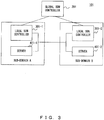
- FIG. 3 is a configuration view of a system according to a first embodiment.
- SDN software defined network
- the global SDN controller 201 is connected to the local SDN controllers 301-i via a network. Furthermore, the local SDN controllers 301-i and the servers 401-i are connected to each other, respectively, via a network.
- the local SDN controller 301-1 and the server 401-1 belong to the sub-domain A.
- the local SDN controller 301-2 and the server 401-2 belong to the sub-domain B.
- the sub-domain is a group of devices determined by a manager.
- the number of the servers 401-i illustrated in FIG. 3 is expressed as one example and is not limited thereto.
- the global SDN controller 201 requests the local SDN controllers 301-i to set the service chains.
- the local SDN controllers 301-i set the service chains. Specifically, the local SDN controllers 301-i set the SFC relay tables of the servers 401-i in the sub-domains to which the local SDN controllers 301-i belong.
- the servers 401-i execute service functions of the network using software.
- the service functions (hereinafter, simply referred to as a service function) of the network are visualized on the servers 401-i.
- Examples of the service function include a firewall, a router, a deep packet inspection (DPI), WAN acceleration, a service quality monitor, and the like.
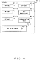
- FIG. 4 is a configuration diagram of the server according to the first embodiment.
- SFF service function forwarder
- the VNF units 411-i-j execute the service functions of the network to the packet.
- the VNF units 411-i-j may be described as the VNFs i-j.
- the SFF unit 421-i transfers the packet to the appropriate service functions (the VNF units 411-i-j) on the basis of service tag information included in the packet and a SFC relay table 461-i.
- the SFC mapper unit 431-i updates the service tag information at the time of outputting the packet to the other sub-domain.
- the communication unit 441-i communicates with the local SDN controller 301-i or the other server 401-i.
- the memory unit 451-i is a memory device that stores data for use in the server 401-i.
- the memory unit 451-i stores the SFC relay table 461-i.
- the SFC relay table 461-i indicates the service chain (a combination of the VNF units 411-i-j applied to the packet) in the sub-domain to which the server 401-i belongs and indicates an output of the packet in the service chain.
- FIGS. 5A and 5B illustrate examples of the SFC relay tables according to the first embodiment.
- the SFC relay table 461-1 illustrated in FIG. 5A is stored in the server 401-1 in the sub-domain A and the SFC relay table 461-2 illustrated in FIG. 5B is stored in the server 401-2 in the sub-domain B.
- the service path ID, the service index, and the output are associated with each other and are described in the SFC relay table 461-i.
- the service path ID is information for identifying the service chain.
- the service path ID indicates a combination of the service functions performed with respect to the packet.
- the service index is information indicating the service function and is information indicating the service function next applied to the packet.
- the service index indicates an order for performing the service function.
- the service index indicates the service function, the sub-domain, or the device of the next output of the packet.
- the initial value of the service index is 255 and the service index that is decremented by one in the order of the VNFs to be transferred is allocated to the VNF of each sub-domain.
- the service chain is configured across the sub-domain A and the sub-domain B to be hereinafter described as illustrated in FIG. 10 .
- the VNFs 1-1 to 1-10 are included in the sub-domain A and the VNFs 2-1 to 2-2 are included in the sub-domain B.
- the packet is transferred and various processes are performed in the order of the VNF 1-1, the VNF 1-2, ..., and the VNF 1-10.
- the packet is transmitted to the sub-domain B.
- the packet is transferred and the various processes are performed in the order of the VNF 2-1 and the VNF 2-2.
- the SFC relay table 461-1 of the server 401-1 in the sub-domain A is set to values as illustrated in FIG. 5A
- the SFC relay table 461-2 of the server 401-2 in the sub-domain B is set to values as illustrated in FIG. 5B .
- the packet is transferred and the various processes are performed in the order of the VNF 1-1, the VNF 1-2, ..., and the VNF 1-10.
- the service index is 255 corresponding to the VNF 1-1 that is an output to which the packet is first transferred in the sub-domain A
- the service index is 254 corresponding to the VNF 1-2 that is an output to which the packet is next transferred.
- the packet is transferred and the various processes are performed in the order of the VNF 2-1 and the VNF 2-2.
- the service index is 255 corresponding to the VNF 2-1 that is an output to which the packet is first transferred in the sub-domain B
- the service index is 254 corresponding to the VNF 2-2 that is an output to which the packet is next transferred.
- the service path ID of each entry in the SFC relay table 461-1 is 100 and the service path ID of each entry in the SFC relay table 461-2 is 100; therefore, the service path ID is expressed as the same value. Therefore, it is understood that the service chain in the sub-domain A indicated in the SFC relay table 461-1 is connected to the service chain in the sub-domain B indicated in the SFC relay table 461-2. Furthermore, the service chain is configured across the sub-domain A and the sub-domain B as illustrated in FIG. 10 .
- the output indicates an output destination of the packet.
- the service function VNF
- the sub-domain, or the device is described.
- the SFF unit 421-i refers to the SFC relay table 461-i, detects the service path ID included in the packet and the output corresponding to the service index, and outputs the packet to the detected output.
- the SFF unit 421-1 when the SFF unit 421-1 receives the packet, the service path ID included in the received packet is 100 and the service index included in the received packet is 255.
- the SFF unit 421-1 when the SFF unit 421-1 receives the packet, the service path ID included in the received packet is 100 and the service index included in the received packet is 245.
- the SFF unit 421-1 transfers the packet to the SFC mapper unit 431-1 and the SFC mapper unit 431-1 outputs the packet to the sub-domain B.
- the SFC mapper unit 431-1 resets the service index of the packet, namely, updates the service index to 255.
- the SFF unit 421-2 when the SFF unit 421-2 receives the packet, the service path ID included in the received packet is 100 and the service index included in the received packet is 255.
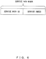
- FIG. 6 illustrates a service path header
- the service tag information is given to the packet and the SFF unit 421-i transfers the packet to the appropriate service function with reference to the service tag information.
- the service tag information is given by a classifier arranged at the entrance of the service chain.
- the service tag information given to the packet includes the service path header.
- the service path header includes the service path ID and the service index.
- the service path ID is information for identifying the service chain.
- the service path ID indicates a combination of the service functions to be performed on the packet.
- the service index is information indicating the number of the service functions to be performed on the packet and is information indicating the service function to be next applied to the packet. For example, an initial value of the service index is 255 and the service index is decremented by one whenever the service index is processed using the VNF units 411-i-j. Therefore, it can be determined by the service index that how many the service functions are performed with respect to the packet, and the service function of the next transfer destination is understood. For example, when the service index of the packet is 254, it is indicated that the service index is processed using one service function. Referring to the SFC relay table 461-1 of FIG. 5A , it is understood that the packet is next transferred to the VNF 1-2.
- FIG. 7 is a configuration diagram of the global SDN controller according to the first embodiment.
- the global SDN controller 201 includes a communication unit 211, a request unit 221, and a memory unit 231.
- the communication unit 211 transmits and receives data to and from the local SDN controller 301-i.
- the request unit 221 requests the local SDN controller 301-i to set the SFC relay table 461-i.
- the memory unit 231 is a memory device that stores data for use in the global SDN controller 201.
- the memory unit 231 stores service chain definition information 241.
- the service chain definition information 241 is information for defining the service chain.
- the service chain definition information 241 includes information such as the service function included in the service chain, an order for applying the service function, the sub-domain to which the service function belongs, etc.
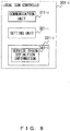
- FIG. 8 is a configuration diagram of the local SDN controller according to the first embodiment.
- the local SDN controller 301-i includes a communication unit 311-i, a setting unit 321-i, and a memory unit 331-i.
- the communication unit 311-i communicates with the global SDN controller 201 and the server 401-i.
- the setting unit 321-i sets the SFC relay table 461-i of the server 401-i.
- the memory unit 331-i is a memory device that stores data for use in the local SDN controller 301-i .
- the memory unit 331-i stores service chain definition information 341-i.
- the service chain definition information 341-i is information for defining the service chain.
- the service chain definition information 341-i includes information such as the service function included in the service chain, an order for applying the service function, the sub-domain to which the service function belongs, etc.
- FIG. 9 illustrates an example of the service chain definition information.
- FIG. 10 illustrates an example of the service chain.
- the service chain definition information 241 and 341-i is expressed as, for example, a linked list form as illustrated in FIG. 9 .
- the configuration of the service chain illustrated in FIG. 10 corresponds to the service chain definition information illustrated in FIG. 9 .
- the VNF 1-1 to the VNF 1-10 are included in the sub-domain A, and the VNF 2-1 and the VNF 2-2 are included in the sub-domain B.
- the packet is transferred and the various processes are performed in the order of the VNF 1-1, the VNF 1-2, ..., and the VNF 1-10.
- the packet is transmitted to the sub-domain B.
- the packet is transferred and the various processes are performed in the order of the VNF 2-1 and the VNF 2-2.
- the service chain is configured across the sub-domain A and the sub-domain B as illustrated in FIG. 10 ; specifically, the service chain is configured including the VNFs of the sub-domain A and the VNFs of the sub-domain B.
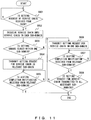
- FIG. 11 is a flowchart of service chain setting request processing of the global SDN controller according to the first embodiment.
- step S601 if the request unit 221 receives a setting request of the service chain from a graphical user interface (GUI) etc. of the global SDN controller, the process proceeds to step S602.
- the service chain definition information is included in the setting request of the service chain.
- step S602 the request unit 221 dissolves the service chain into the service chain in each sub-domain on the basis of the received service chain definition information.
- the service chain is dissolved into the service chain (the VNF 1-1, the VNF 1-2, ..., and the VNF 1-10) in the sub-domain A and the service chain (the VNF 2-1 and the VNF 2-2) in the sub-domain B.
- step S603 the request unit 221 determines whether the setting change is closed within one sub-domain. Specifically, the request unit 221 compares the service chain definition information received this time and the current service chain definition information, and determines whether a changed portion exists only in the one sub-domain. If the setting change is closed within the one sub-domain, the process proceeds to step S604, and if the setting change is not closed within the one sub-domain, the process proceeds to step S606.
- step S604 the request unit 221 transmits the setting request for the service chain to the local SDN controller 301-i in the sub-domain in which the service chain is changed.
- the received service chain definition information is included.
- step S605 when the request unit 221 receives a setting completion notification of the service chain from the local SDN controller 301-i, the process ends.
- step S606 the request unit 221 transmits the setting request for the service chain to the SDN controller 301-i of one sub-domain within the sub-domain to which the setting request for the service chain has not yet been transmitted and in which the service chain has been changed.
- step S607 if the request unit 221 receives the setting completion notification of the service chain from the local SDN controller 301-i, the process proceeds to step S608.
- step S608 if the setting request for the service chain is transmitted to all the sub-domains in which the service chain is changed, the process ends. If the setting request for the service chain is not transmitted to all the sub-domains in which the service chain is changed, the process returns to step S606.
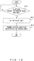
- FIG. 12 is a flowchart of service chain setting processing of the local SDN controller according to the first embodiment.
- step S611 if the communication unit 311-i receives the setting request for the service chain from the global SDN controller 201, the process proceeds to step S612.
- step S612 the setting unit 321-i sets the SFC relay table 461-i on the basis of the service chain definition information included in the setting request for the service chain.
- step S613 the setting unit 321-i transmits the setting completion notification of the service chain to the global SDN controller 201.
- FIG. 13 illustrates an example of the service chain.
- FIG. 14 illustrates an example of the SFC relay table after the change.
- the service chain is supposed to be changed into a state as illustrated from FIG. 10 to FIG. 13 .
- the VNF 1-11 is supposed to be added to the service chain in the sub-domain A.
- the SFC relay table 461-1 of the server 401-1 is a state illustrated in FIG. 5A .
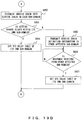
- FIG. 15 is a flowchart of the packet relay processing of the server according to the first embodiment.
- step S621 the communication unit 441-i receives the packet.
- step S622 the SFF unit 421-i extracts the service tag information of the packet. Specifically, the SFF unit 421-i extracts the service path ID and service index of the packet.
- step S623 the SFF unit 421-i searches the SFC relay table 461-i using as a search key the service path ID and service index of the packet, and specifies the next output of the corresponding packet.
- step S624 on the basis of search results, the SFF unit 421-i determines whether the next output of the packet is the VNF unit 411-i-j in the same server 401-i. If the next output of the packet is the VNF unit 411-i-j in the same server 401-i, the process proceeds to step S625 and if the next output of the packet is not the VNF unit 411-i-j in the same server 401-i, the process proceeds to step S629.
- step S625 the SFF unit 421-i transfers the packet to the VNF unit 411-i-j of the next output on the basis of the service index of the packet and the SFC relay table 461-i.
- step S626 the VNF units 411-i-j perform predetermined network service processing (for example, a firewall) on the packet.
- predetermined network service processing for example, a firewall
- step S627 the VNF units 411-i-j decrement the service index of the packet by one.
- step S628 the VNF units 411-i-j output the packet to the SFF unit 421-i.
- step S629 the SFC mapper unit 431-i refers to the service index of the packet and the SFC relay table 461-i, and determines whether the next output of the packet is the other sub-domain. If the next output of the packet is the other sub-domain, the process proceeds to step S630 and if the next output of the packet is not the other sub-domain (specifically, if the next output of the packet is another server in the same sub-domain), the process proceeds to step S631.
- the SFC mapper unit 431-i resets the service index of the packet. Specifically, the SFC mapper unit 431-i changes the service index of the packet into a predetermined value (for example, 255, which is the initial value of the service index).
- the SFC relay table 461-i may furthermore include reset information indicating whether to reset the service index and the SFC mapper unit 431-i may reset the service index of the packet on the basis of the reset information.
- the SFC mapper unit 431 resets the service index of the packet.
- the reset information indicating that the service index has been reset is set to the entry the output of which indicates the other sub-domain among the entries of the SFC relay table 461-i.
- step S631 the SFC mapper unit 431-i transmits the packet to the next output via the communication unit 441-i.
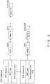
- FIG. 16 illustrates the service index of the VNF before and after the change in the service chain according to the first embodiment.
- FIG. 16 illustrates the service chain before the change and the lower side of FIG. 16 illustrates the service chain after the change.
- the service chain Before the change in the service chain, the service chain includes the VNF 1-1 of the sub-domain A and the VNF 2-1 of the sub-domain B.
- the packet is processed using each VNF in the order of the VNF 1-1 and the VNF 2-1.
- the service index corresponding to the VNF 1-1 is 255
- the SFC relay table 461-2 of the sub-domain B the service index corresponding to the VNF 2-1 is 255.
- the SFC mapper unit 431-1 in the sub-domain A changes (resets) the service index of the packet to 255. Because the service index of the received packet is 255, the SFF unit 422-2 in the sub-domain B transfers the packet to the VNF 2-1.
- the VNF 1-2 is supposed to be added to the service chain in the sub-domain A.
- the packet is processed using each VNF in the order of the VNF 1-1, the VNF 1-2, and the VNF 2-1.
- the SFC relay table 461-1 is changed using the local SDN controller 301-1, and after the service chain in the sub-domain A is changed, the service index corresponding to the VNF 1-1 is 255 and the service index corresponding to the VNF 1-2 changes to 254 in the SFC relay table 461-1 of the sub-domain A.
- the service index corresponding to the VNF 2-1 is 255 and is not changed.
- the SFC mapper unit 431-1 in the sub-domain A changes (resets) the service index of the packet to 255. Because the service index of the received packet is 255, the SFF unit 422-2 in the sub-domain B transfers the packet to the VNF 2-1.
- the SFC relay table 461-2 of the sub-domain B is not changed.
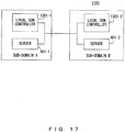
- FIG. 17 illustrates a modification of a configuration diagram of the system according to the first embodiment.
- the local SDN controllers 1301-i and the servers 401-i are connected to each other, respectively, via a network.
- the local SDN controller 1301-1 and the server 401-1 belong to the sub-domain A.
- the local SDN controller 1301-2 and the server 401-2 belong to the sub-domain B.
- the number of the servers 401-i illustrated in FIG. 17 is expressed as one example and is not limited thereto.
- FIG. 18 is a configuration diagram of the local SDN controller of the modification.
- the local SDN controller 1301-i includes a communication unit 1311-i, a setting unit 1321-i, an inquiry unit 1331-i, an update unit 1341-i, a display control unit 1351-i, and a memory unit 1361-i.
- the communication unit 1311-i communicates with the other local SDN controller 1301-i and the server 401-i.
- the setting unit 1321-i sets the SFC relay table 461-i of the server 401-i.
- the inquiry unit 1331-i inquires with the other local SDN controller 1301-i.
- the update unit 1341-i updates the service chain definition information 1371-i.
- the display control unit 1351-i controls a display of a display unit (not illustrated) such as a display etc. included in the local SDN controller 1301-i.
- the memory unit 1361-i is a memory device that stores data for use in the local SDN controller 1301-i.
- the memory unit 1361-i stores the service chain definition information 1371-i.
- the service chain definition information 1371-i is the same as the service chain definition information 341-i, and therefore descriptions will be omitted.
- FIGS. 19A and 19B illustrate a flowchart of service chain setting processing of the local SDN controller of the modification.
- step S651 the setting unit 1321-i determines whether the setting request for the service chain has been received from a GUI etc. of the local SDN controller 1301-i. If the setting request for the service chain has been received, the process proceeds to step S652, and if the setting request for the service chain has not been received, the process proceeds to step S658. In the setting request for the service chain, the service chain definition information is included.
- step S652 the setting unit 1321-i dissolves the service chain into the service chain in each sub-domain on the basis of the received service chain definition information.
- the service chain is dissolved into the service chain (the VNF 1-1, the VNF 1-2, ..., and the VNF 1-10) in the sub-domain A and the service chain (the VNF 2-1 and the VNF 2-2) in the sub-domain B.
- step S653 the setting unit 1321-i determines whether the setting change is closed within its own sub-domain. Specifically, the setting unit 1321-i compares the service chain definition information received this time and the current service chain definition information, and determines whether a changed portion of the service chain exists only in the sub-domain to which the setting unit 1321-i belongs. If the changed portion is closed within its own sub-domain, the process proceeds to step S654, and if the changed portion is not closed within its own sub-domain, the process proceeds to step S655.
- step S654 the setting unit 1321-i sets the SFC relay table 461-i of the server 401-i in its own sub-domain on the basis of the received service chain definition information.
- step S655 the setting unit 1321-i transmits the received service chain definition information and service chain setting request to the other affected sub-domain (specifically, the other sub-domain in which the service chain is changed).
- step S656 if the setting unit 1321-i receives a response from the other affected sub-domain, the process proceeds to step S657.
- step S657 the setting unit 1321-i sets the SFC relay table 461-i of the server 401-i in its own sub-domain.
- step S658 the setting unit 1321-i determines whether the service chain setting request has been received from the other sub-domain. If the service chain setting request has been received from the other sub-domain, the process proceeds to step S662, and if the service chain setting request has not been received from the other sub-domain, the process proceeds to step S659.
- step S659 the setting unit 1321-i determines whether an inquiry on the service chain definition information has been received from a user. If the inquiry on the service chain definition information has been received from the user, the process proceeds to step S663, and if the inquiry on the service chain definition information has not been received from the user, the process proceeds to step S660.
- step S660 the setting unit 1321-i determines whether the inquiry on the service chain definition information has been received from the local SDN controller 1301-i in the other sub-domain. If the inquiry on the service chain definition information has been received from the local SDN controller 1301-i in the other sub-domain, the process proceeds to step S661, and if the inquiry on the service chain definition information has not been received from the local SDN controller 1301-i in the other sub-domain, the process ends.
- step S661 the inquiry unit 1331-i transmits the service chain definition information for its own sub-domain included in the service chain definition information 1371-i to the local SDN controller 1301-i in the other sub-domain that is an inquiry source.
- step S662 the setting unit 1321-i sets the SFC relay table 461-i of the server 401-i in its own sub-domain.
- step S663 the inquiry unit 1331-i determines whether the service chain definition information needs to be inquired of the other sub-domain. If the service chain definition information needs to be inquired of the other sub-domain, the process proceeds to step S664, and if the service chain definition information does not need to be inquired of the other sub-domain, the process proceeds to step S667 .
- the inquiry unit 1331-i determines that the service chain definition information needs to be inquired of the other sub-domain.
- step S664 the inquiry unit 1331-i transmits the inquiry on the service chain definition information to the local SDN controller 1301-i in the other sub-domain.
- step S665 if the inquiry unit 1331-i receives a response from the local SDN controller 1301-i in the other sub-domain, the process proceeds to step S666.
- step S666 the update unit 1341-i updates the service chain definition information 1371-i on the basis of the response received from the local SDN controller 1301-i in the other sub-domain.
- step S667 the display control unit 1351-i displays the service chain definition information 1371-i.
- FIG. 20 is a configuration diagram of a system according to a second embodiment.
- the SDN controller 2301 and the servers 2401-i are connected to each other, respectively, via a network.
- the server 2401-1 belongs to the sub-domain A.
- the SDN controller 2301 and the server 2401-2 belong to the sub-domain B.
- the sub-domain is called a group of devices determined by a manager.
- the number of the servers 2401-i illustrated in FIG. 20 is expressed as one example and is not limited thereto.
- the SDN controller 2301 sets the service chain. Specifically, the SDN controller 2301 sets the SFC relay tables of the servers 2401-i.
- the servers 2401-i execute the service function of the network using software.
- the service function (hereinafter, simply referred to as a service function) of the network is visualized on the servers 2401-i.
- the service function include a firewall, a router, a deep packet inspection (DPI), WAN acceleration, a service quality monitor, and the like.
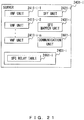
- FIG. 21 is a configuration diagram of the server.
- VNF units 2411-i-j, the SFF unit 2421-i, the SFC mapper unit 2431-i, and the communication unit 2441-i have the same functions as those of the VNF units 411-i-j , the SFF unit 421-i, the SFC mapper unit 431-i, and the communication unit 441-i, respectively, and therefore descriptions will be omitted.
- the memory unit 2451-i is a memory device that stores data for use in the server 2401-i.
- the memory unit 2451-i stores an SFC relay table 2461-i .
- the SFC relay table 2461-i indicates the service chain (a combination of the VNF units 2411-i-j applied to the packet) in the sub-domain to which the server 2401-i belongs, and indicates outputs of the packet in the service chain.
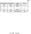
- FIGS. 22A and 22B illustrate examples of the SFC relay tables.
- the SFC relay table 2461-1 illustrated in FIG. 22A is stored in the server 2401-1 in the sub-domain A and the SFC relay table 2461-2 illustrated in FIG. 22B is stored in the server 2401-2 in the sub-domain B.
- the service path ID, the service index, the output, and the path ID are associated with each other and are described in the SFC relay table 2461-i.
- the service path ID is information for identifying the service chain in its own sub-domain.
- the service path ID indicates a combination of the service functions to be performed on the packet in its own sub-domain.
- the service index is information indicating the service functions and is information indicating the service function to be next applied to the packet.
- the service index indicates an order for performing the service functions.
- the service index indicates the service function, sub-domain, and device of the next output of the packet.
- an initial value of the service index is 255 and the service index is allocated to the VNF, decremented by one in the order of the VNFs to be transferred in each sub-domain.
- the service chain definition information is information as illustrated in FIG. 9 .
- the packet is transferred and the various processes are performed in the order of the VNF 1-1, the VNF 1-2, ..., and the VNF 1-10.
- the packet is transferred and the various processes are performed in the order of the VNF 2-1 and the VNF 2-2.
- the output indicates an output of the packet.
- the service function the VNF
- the sub-domain the sub-domain, or the device is described.
- the path ID indicates a value of the service path ID of the packet to be set at the time of outputting the packet.
- the path ID is information for identifying the service chain in the sub-domain of the output of the packet.
- the path ID indicates a correspondence relationship between the service chain in its own sub-domain and the service chain in the sub-domain of the output of the packet.
- the service chain is configured across the sub-domain A and the sub-domain B as illustrated in FIG. 10 .
- the SFC relay table 2461-1 of the server 2401-1 in the sub-domain A is set to values as illustrated in FIG. 22A and the SFC relay table 2461-2 of the server 2401-2 in the sub-domain B is set to values as illustrated in FIG. 22B .
- the service chain in the sub-domain A indicated in the SFC relay table 2461-1 is connected to the service chain in the sub-domain B indicated in the SFC relay table 2461-2. Furthermore, the service chain is configured across the sub-domain A and the sub-domain B as illustrated in FIG. 10 .
- the SFF unit 2421-i refers to the SFC relay table 2461-i, detects the output corresponding to the service path ID and service index included in the packet, and outputs the packet to the detected output.
- the SFF unit 2421-1 when the SFF unit 2421-1 receives the packet, the service path ID included in the received packet is 100 and the service index included in the received packet is 255.
- the SFF unit 2421-1 transfers the packet to the SFC mapper unit 2431-1 and the SFC mapper unit 2431-1 outputs the packet to the sub-domain B.
- the SFC mapper unit 2431-1 resets the service index of the packet, namely, updates the service index to 255. Also, the SFC mapper unit 2431-1 changes the service path ID of the packet from 100 to 200.
- the SFF unit 2421-2 receives the packet, the service path ID included in the received packet is 200 and the service index included in the received packet is 255.
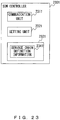
- FIG. 23 is a configuration diagram of the SDN controller according to the second embodiment.
- the SDN controller 2301 includes a communication unit 2311, a setting unit 2321, and a memory unit 2331.
- the communication unit 2311 communicates with the servers 2401-i.
- the setting unit 2321 sets the SFC relay tables 2461-i of the servers 2401-i.
- the memory unit 2331 is a memory device that stores data for use in the SDN controller 2301.
- the memory unit 2331 stores the service chain definition information 2341.
- the service chain definition information 2341 is the same as the service chain definition information 341-i, and therefore descriptions will be omitted.
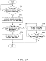
- FIG. 24 is a flowchart of service chain setting processing according to the second embodiment.
- step S701 if the setting unit 2321 receives a setting request for the service chain using a GUI etc. of the SDN controller 2301, the process proceeds to step S702.
- the service chain definition information is included.
- step S702 the setting unit 2321 dissolves the service chain into the service chain in each sub-domain on the basis of the received service chain definition information.
- the service chain is dissolved into the service chain (the VNF 1-1, the VNF 1-2, ..., and the VNF 1-10) in the sub-domain A and the service chain (the VNF 2-1 and the VNF 2-2) in the sub-domain B.
- step S703 the setting unit 2321 determines whether the setting change is closed within one sub-domain. Specifically, the setting unit 2321 compares the service chain definition information received this time and the current service chain definition information, and determines whether a changed portion of the service chain exists only in the one sub-domain. If the setting change is closed within the one sub-domain, the process proceeds to step S704, and if the setting change is not closed within the one sub-domain, the process proceeds to step S705.
- step S704 the setting unit 2321 sets the SFC relay table 2461-i of the sub-domain in which the service chain is changed on the basis of the received service chain definition information.
- step S705 the setting unit 2321 sets the SFC relay table 2461-i of one sub-domain that has not yet been set in the sub-domain in which the service chain is changed on the basis of the received service chain definition information.
- step S706 if the setting unit 2321 sets the SFC relay tables 2461-i of all the sub-domains in which the service chain is changed, the process ends, and if the setting unit 2321 does not set the SFC relay tables 2461-i of all the sub-domains in which the service chain is changed, the process returns to step S705.
- FIG. 25 is a flowchart illustrating the packet relay processing of the server according to the second embodiment.
- step S721 the communication unit 2441-i receives the packet.
- step S722 the SFF unit 2421-i extracts the service tag information of the packet. Specifically, the SFF unit 2421-i extracts the service path ID and service index of the packet.
- step S723 the SFF unit 2421-i searches the SFC relay table 461-i using as a search key the service path ID and service index of the packet, and detects the next output of the corresponding packet.
- step S724 on the basis of search results, the SFF unit 2421-i determines whether the next output of the packet is the VNF units 2411-i-j in the same server 2401-i. If the next output of the packet is the VNF units 2411-i-j in the same server 2401-i, the process proceeds to step S725 and if the next output of the packet is no the VNF units 2411-i-j in the same server 2401-i, the process proceeds to step S729.
- step S725 the SFF unit 2421-i transfers the packet to the VNF unit 2411-i-j of the next output on the basis of the service index of the packet and the SFC relay table 2461-i.
- step S726 the VNF unit 2411-i-j performs predetermined network service processing (for example, a firewall) to the packet.
- predetermined network service processing for example, a firewall
- step S727 the VNF unit 2411-i-j decrements the service index of the packet by one.
- step S728 the VNF unit 2411-i-j outputs the packet to the SFF unit 2421-i.
- step S729 the SFC mapper unit 2431-i refers to the service index of the packet and the SFC relay table 2461-i, and determines whether the next output of the packet is the other sub-domain. If the next output of the packet is the other sub-domain, the process proceeds to step S730, and if the next output of the packet is not the other sub-domain (if the next output of the packet is the other server in the same sub-domain), the process proceeds to step S731.
- step S731 the SFC mapper unit 2431-i transmits the packet to the next output via the communication unit 2441-i.
- FIG. 26 illustrates the service index of the VNFs before and after the change in the service chain according to the second embodiment.
- FIG. 26 illustrates the service chain before the change and the lower side of FIG. 26 illustrates the service chain after the change.
- the service chain Before the change in the service chain, the service chain includes the VNF 1-1 of the sub-domain A and the VNF 2-1 of the sub-domain B.
- the packet is processed using each VNF in the order of the VNF 1-1 and the VNF 2-1.
- the service index corresponding to the VNF 1-1 is 255
- the service index corresponding to the VNF 2-1 is 255.
- the SFC mapper unit 2431-1 in the sub-domain A changes the service path ID of the packet to 200 and changes (resets) the service index of the packet to 255. Because the service index of the received packet is 255, the SFF unit 422-2 in the sub-domain B transfers the packet to the VNF 2-1.
- the VNF 1-2 is supposed to be added to the service chain in the sub-domain A.
- the packet is processed using each VNF in the order of the VNF 1-1, the VNF 1-2, and the VNF 2-1.
- the SFC relay table 2461-1 is changed using the SDN controller 2301 and, after the change in the service chain in the sub-domain A in the SFC relay table 2461-1 of the sub-domain A, the service index corresponding to the VNF 1-1 is 255 and the service index corresponding to the VNF 1-2 changes to 254.
- the service index corresponding to the VNF 2-1 is 255 and is not changed.
- the SFC mapper unit 2431-1 in the sub-domain A changes the service path ID of the packet to 200 and changes (resets) the service index of the packet to 255. Because the service index of the received packet is 255, the SFF unit 422-2 in the sub-domain B transfers the packet to the VNF 2-1.
- the SFC relay table 2461-2 of the sub-domain B is not changed.
- the SFC mapper unit 2431-i may select the transmission destination.
- the server 2401-i may regularly collect information on the load state, the line state, the terminal performance, etc. or may receive the information from the other server 2401-i or the SDN controller 2301.
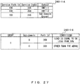
- FIG. 27 illustrates a modification of the SFC relay table according to the second embodiment.
- the SFC relay table 2461-1 may be configured using SFC relay tables 2461-1-A and 2461-1-B as illustrated in FIG. 27 .
- the SFC relay tables 2461-1-A and 2461-1-B are stored in the server 2401-1 in the sub-domain A.
- the service path ID, the service index, and the output are associated with each other and are described in the SFC relay table 2461-1-A.
- the service path ID is information for identifying the service chain.
- the service path ID indicates a combination of the service functions to be performed on the packet.
- the service index is information indicating the service function and is information indicating the service function to be next applied to the packet.
- the service index indicates an order for performing the service function. Also, the service index indicates the service function, sub-domain, or device of the next output of the packet.
- the output indicates an output of the packet.
- the service function (VNF) and a group of the sub-domain are described.
- the service path ID, the service index, and the output are associated with each other and are described in the SFC relay table 2461-1-A.
- the group, the sub-domain, the path ID, and the conditions are associated with each other and are described in the SFC relay table 2461-1-B.
- the group indicates a group of the sub-domain.
- the sub-domain indicates a sub-domain of the output.
- the path ID indicates a value of the service path ID of the packet to be set at the time of outputting the packet.
- the path ID is information for identifying the service chain in the sub-domain of the output of the packet.
- the path ID indicates a correspondence relationship between the service chain in its own sub-domain and the service chain in the sub-domain of the output of the packet.
- the conditions are conditions for use in the selection of the output of the packet.
- the conditions for example, the conditions are described based on the load state, the line state of the output of the packet, or the terminal performance. "The load is equal to or less than 50%" is described, for example, in the conditions corresponding to the sub-domain B of the SFC relay table 2461-1-B. This indicates that when the load of the server in the sub-domain B is equal to or less than 50%, the sub-domain B is selected as the output.
- the SFF unit 2421-1 refers to the SFC relay tables 2461-1-A and 2461-1-B, detects the output corresponding to the service path ID and service index included in the packet, and outputs the packet to the detected output.
- the SFF unit 2421-1 when the SFF unit 2421-1 receives the packet, the service path ID included in the received packet is 100 and the service index included in the received packet is 255.
- the SFC mapper unit 2431-1 refers to the SFC relay table 2461-1-B, detects the entry corresponding to the group 1, detects the sub-domain relevant to the conditions in the entry, and outputs the packet to the detected sub-domain. For example, when the load of the server in the sub-domain B is equal to or less than 50%, the SFC mapper unit 2431-1 outputs the packet to the sub-domain B. At this time, the SFC mapper unit 2431-1 resets the service index of the packet, namely, updates the service index to 255. Also, the SFC mapper unit 2431-1 changes the service path ID of the packet from 100 to 200.
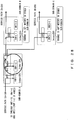
- FIG. 28 illustrates the modification of the packet relay processing and the service index of the VNF according to the second embodiment.
- FIG. 28 illustrates the case of adding the VNF 1-2 to the service chain in the sub-domain A.
- the service chain Before the change in the service chain, the service chain includes the VNF 1-1 of the sub-domain A and the VNF 2-1 of the sub-domain B.
- the packet is processed using each VNF in the order of the VNF 1-1 and the VNF 2-1 or in the order of the VNF 1-1 and the VNF 1-3.
- the service index corresponding to the VNF 1-1 is 255
- the service index corresponding to the VNF 2-1 is 255
- the service index corresponding to the VNF 3-1 is 255.
- the SFC mapper unit in the sub-domain A Before the change in the service chain, the SFC mapper unit in the sub-domain A outputs the packet output from the VNF 1-1 to either the sub-domain B or the sub-domain C in accordance with the conditions.
- the SFC mapper unit 2431-1 in the sub-domain A changes the service path ID of the packet to 200 and changes (resets) the service index of the packet to 255. Because the service index of the received packet is 255, the SFF unit in the sub-domain B transfers the packet to the VNF 2-1.
- the SFC mapper unit 2431-1 in the sub-domain A changes the service path ID of the packet to 300 and changes (resets) the service index of the packet to 255. Because the service index of the received packet is 255, the SFF unit in the sub-domain C transfers the packet to the VNF 3-1.
- the VNF 1-2 is supposed to be added to the service chain in the sub-domain A.
- the packet is processed using each VNF in the order of the VNF 1-1, the VNF 1-2, and the VNF 2-1 or in the order of the VNF 1-1, the VNF 1-2, and the VNF 3-1.
- the service index corresponding to the VNF 1-1 is 255 and the service index corresponding to the VNF 1-2 changes to 254.
- the service index corresponding to the VNF 2-1 is 255 and is not changed.
- the service index corresponding to the VNF 3-1 is 255 and is not changed.
- the SFC mapper unit in the sub-domain A outputs the packet output from the VNF 1-2 to either the sub-domain B or the sub-domain C in accordance with the conditions .
- the SFC mapper unit in the sub-domain A changes the service path ID of the packet to 200 and changes (resets) the service index of the packet to 255. Because the service index of the received packet is 255, the SFF unit 422-2 in the sub-domain B transfers the packet to the VNF 2-1.
- the SFC mapper unit in the sub-domain A changes the service path ID of the packet to 300 and changes (resets) the service index of the packet to 255. Because the service index of the received packet is 255, the SFF unit 422-2 in the sub-domain C transfers the packet to the VNF 2-1.
- the sub-domain of the output of the packet can be selected in response to the conditions of the load state, the line state, the terminal performance, or the like.
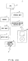
- FIG. 29 is a configuration diagram illustrating an information processing device (computer).
- the SDN controllers 201, 301-i, 1301-i, and 2301 and the servers 401-i and 2401-i of the embodiments can be implemented, for example, using the information processor (computer) 1 as illustrated in FIG. 29 .
- the information processing device 1 includes a Central Processing Unit (CPU) 2, a memory 3, an input unit 4, an output unit 5, a storage unit 6, a recording medium driving unit 7, and a network connection device 8, and they are connected to each other via a bus 9.
- CPU Central Processing Unit
- memory 3 an input unit 4, an output unit 5, a storage unit 6, a recording medium driving unit 7, and a network connection device 8, and they are connected to each other via a bus 9.
- the CPU 2 is a central processor that controls the entire information processing device 1.
- the CPU 2 performs as the VNF units 411-i-j and 2411-i-j , the SFF units 431-i and 2431-i, or the SFC mapper units 431-i and 2431-i. Also, the CPU 2 acts as the request unit 221, the setting units 321-i, 1321-i, and 2321, the inquiry unit 1331-i, the update unit 1341-i, or the display control unit 1351-i.
- the memory 3 is a memory such as a read-only memory (ROM), a random access memory (RAM), etc. that temporarily stores programs or data stored in the storage unit 6 (or a portable recording medium 10).
- ROM read-only memory
- RAM random access memory
- the CPU 2 By executing programs using the memory 3, the CPU 2 performs the above-described various processes.
- a program code itself read out from the portable recording medium 10 etc. implements functions of the embodiments.
- the input device 4 is used for an input of an instruction or information from the user or operator, an acquisition of data for use in the information processing device 1, or the like.
- Examples of the input unit 4 include a keyboard, a mouse, a touch panel, a camera, and the like.
- the output unit 5 is a unit that outputs an inquiry or processing results to the user or operator, or operates under the control of the CPU 2. Examples of the output unit 5 include a display, a printer, and the like.
- Examples of the storage unit 6 include a magnetic disk device, an optical disk device, a tape device, and the like.
- the information processing device 1 stores the above-described programs and data in the storage unit 6 and reads them out from the storage unit 6 to the memory 3 for use.
- the memory 3 or the storage unit 6 corresponds to the memory units 231, 331-i, 451-i, 1361-i, 2331, and 2451-i.
- the recording medium driving unit 7 drives the portable recording medium 10 and accesses recording contents thereof.
- any computer-readable recording medium can be used such as a memory card, a flexible disk, a compact disk read only memory (CD-ROM), an optical disk, a magnetic optical disk, etc.
- the user stores the above-described programs and data in this portable recording medium 10 and reads them out to the memory 3 for use.
- the network connection device 8 is a communication interface that can be connected to any communication network such as a local area network (LAN), a wide area network (WAN), etc. and that performs data conversion accompanied by communication.
- the network connection device 8 transmits data to a device to which it is connected via the communication network or receives data from a device to which it is connected via the communication network.
- the network connection device 8 corresponds to the communication units 211, 311-i, 441-i, 1311-i, and 2441-i.
Landscapes
- Engineering & Computer Science (AREA)
- Computer Networks & Wireless Communication (AREA)
- Signal Processing (AREA)
- Data Exchanges In Wide-Area Networks (AREA)
Claims (4)
- Paketweiterleitungsprogramm zum Weiterleiten eines Pakets in einer ersten Subdomäne aus einer Vielzahl von Subdomänen in einer Servicekette, welche über die Vielzahl von Subdomänen hinweg konfiguriert ist, welches, wenn das Programm von einem Computer (401) ausgeführt wird, den Computer (401) in der ersten Subdomäne veranlasst, einen Prozess auszuführen, wobei der Prozess umfasst:Empfangen des Pakets, welches Identifikationsinformationen, welche eine Kombination einer Vielzahl von Servicefunktionen angeben, welche in der Servicekette beinhaltet sind, und einen Index, welcher eine Reihenfolge für das Anwenden der Servicefunktion angibt, beinhaltet, wobei der Index ein vorbestimmter Wert ist;Festlegen eines Übertragungsziels, welches den in dem Paket beinhalteten Identifikationsinformationen und dem in dem Paket beinhalteten Index entspricht, auf einer Basis von Weiterleitungsinformationen, mit welchen Identifikationsinformationen, welche eine Kombination von einer Vielzahl von Servicefunktionen, welche in der Servicekette beinhaltet sind, angeben, ein Index, welcher eine Reihenfolge für das Anwenden der Servicefunktion angibt, und das Übertragungsziel verknüpft sind;wenn das festgelegte Übertragungsziel eine Servicefunktion in der ersten Subdomäne ist, Anwenden einer Servicefunktion in der ersten Subdomäne, welche dem festgelegten Übertragungsziel entspricht, auf das Paket und Verringern des Index um eins;Ändern des in dem Paket beinhalteten Index in den vorbestimmten Wert, wenn das festgelegte Übertragungsziel eine zweite Subdomäne aus der Vielzahl von Subdomänen ist; undÜbertragen, des Pakets, welches die in dem Paket beinhalteten Identifikationsinformationen beinhaltet, und den Index des vorbestimmten Wertes an das festgelegte Übertragungsziel.
- Paketweiterleitungsprogramm nach Anspruch 1 zum Weiterleiten eines Pakets in einer ersten Subdomäne aus einer Vielzahl von Subdomänen in einer Servicekette, welche über die Vielzahl von Subdomänen hinweg konfiguriert ist, welches, wenn das Programm von einem Computer (2401) ausgeführt wird, den Computer (2401) in der ersten Subdomäne veranlasst, einen Prozess auszuführen, wobei der Prozess weiter umfasst:
Ändern des in dem Paket beinhalteten Index in den vorbestimmten Wert und Ändern der in dem Paket beinhalteten Identifikationsinformationen in Identifikationsinformationen in dem festgelegten Übertragungsziel, wenn das festgelegte Übertragungsziel eine zweite Subdomäne aus der Vielzahl von Subdomänen ist. - Paketweiterleitungsverfahren zum Weiterleiten eines Pakets in einer ersten Subdomäne aus einer Vielzahl von Subdomänen in einer Servicekette, welche über die Vielzahl von Subdomänen hinweg konfiguriert ist, wobei das Paketweiterleitungsverfahren einen Computer (401) veranlasst, einen Prozess auszuführen, wobei das Paketweiterleitungsverfahren umfasst:Empfangen des Pakets, welches Identifikationsinformationen, welche eine Kombination einer Vielzahl von Servicefunktionen angeben, welche in der Servicekette beinhaltet sind, und einen Index, welcher eine Reihenfolge für das Anwenden der Servicefunktion angibt, beinhaltet, wobei der Index ein vorbestimmter Wert ist;Festlegen eines Übertragungsziels, welches den in dem Paket beinhalteten Identifikationsinformationen und dem in dem Paket beinhalteten Index entspricht, auf einer Basis von Weiterleitungsinformationen, mit welchen Identifikationsinformationen, welche eine Kombination von einer Vielzahl von Servicefunktionen, welche in der Servicekette beinhaltet sind, angeben, ein Index, welcher eine Reihenfolge für das Anwenden der Servicefunktion angibt, und das Übertragungsziel verknüpft sind;wenn das festgelegte Übertragungsziel eine Servicefunktion in der ersten Subdomäne ist, Anwenden einer Servicefunktion in der ersten Subdomäne, welche dem festgelegten Übertragungsziel entspricht, auf das Paket und Verringern des Index um eins;Ändern des in dem Paket beinhalteten Index in den vorbestimmten Wert, wenn das festgelegte Übertragungsziel eine zweite Subdomäne aus der Vielzahl von Subdomänen ist; undÜbertragen, des Pakets, welches die in dem Paket beinhalteten Identifikationsinformationen beinhaltet, und den Index des vorbestimmten Wertes an das festgelegte Übertragungsziel.
- Paketweiterleitungsverfahren nach Anspruch 3 zum Weiterleiten eines Pakets in einer ersten Subdomäne aus einer Vielzahl von Subdomänen in einer Servicekette, welche über die Vielzahl von Subdomänen hinweg konfiguriert ist, wobei das Paketweiterleitungsverfahren einen Computer (2401) veranlasst, einen Prozess auszuführen, wobei das Paketweiterleitungsverfahren weiter umfasst:
Ändern des in dem Paket beinhalteten Index in den vorbestimmten Wert und Ändern der in dem Paket beinhalteten Identifikationsinformationen in Identifikationsinformationen in dem festgelegten Übertragungsziel, wenn das festgelegte Übertragungsziel eine zweite Subdomäne aus der Vielzahl von Subdomänen ist.
Applications Claiming Priority (1)
| Application Number | Priority Date | Filing Date | Title |
|---|---|---|---|
| JP2016026411A JP6617594B2 (ja) | 2016-02-15 | 2016-02-15 | パケット中継プログラムおよびパケット中継方法 |
Publications (3)
| Publication Number | Publication Date |
|---|---|
| EP3206349A1 EP3206349A1 (de) | 2017-08-16 |
| EP3206349A3 EP3206349A3 (de) | 2017-10-25 |
| EP3206349B1 true EP3206349B1 (de) | 2020-07-29 |
Family
ID=58043840
Family Applications (1)
| Application Number | Title | Priority Date | Filing Date |
|---|---|---|---|
| EP17153020.7A Active EP3206349B1 (de) | 2016-02-15 | 2017-01-25 | Paketweiterleitungsprogramm und paketweiterleitungsverfahren |
Country Status (3)
| Country | Link |
|---|---|
| US (1) | US10171342B2 (de) |
| EP (1) | EP3206349B1 (de) |
| JP (1) | JP6617594B2 (de) |
Families Citing this family (6)
| Publication number | Priority date | Publication date | Assignee | Title |
|---|---|---|---|---|
| CN111628921B (zh) | 2019-02-27 | 2021-07-20 | 华为技术有限公司 | 一种报文的处理方法、报文转发装置以及报文处理装置 |
| CN112491739A (zh) * | 2020-07-10 | 2021-03-12 | 中兴通讯股份有限公司 | 一种业务流量处理方法及装置 |
| CN114244629B (zh) * | 2021-03-30 | 2024-04-16 | 支付宝(杭州)信息技术有限公司 | 跨链访问控制方法和装置 |
| CN112738139B (zh) * | 2021-03-30 | 2021-07-06 | 支付宝(杭州)信息技术有限公司 | 一种跨链访问控制方法和装置 |
| JP7613594B2 (ja) * | 2021-08-18 | 2025-01-15 | 日本電信電話株式会社 | 通信制御装置、通信制御方法及び通信制御プログラム |
| WO2026033629A1 (ja) * | 2024-08-06 | 2026-02-12 | Ntt株式会社 | パケット処理装置およびパケット転送方法 |
Family Cites Families (5)
| Publication number | Priority date | Publication date | Assignee | Title |
|---|---|---|---|---|
| US10218615B2 (en) | 2014-02-06 | 2019-02-26 | Nec Corporation | Network system, network control method and control apparatus |
| JP6131203B2 (ja) | 2014-02-17 | 2017-05-17 | 日本電信電話株式会社 | 装置選択ネットワークシステム、装置選択サーバおよびプログラム |
| JP6076275B2 (ja) | 2014-02-18 | 2017-02-08 | 日本電信電話株式会社 | 通信ネットワークの経路制御連携システム及び方法 |
| US9537752B2 (en) | 2014-07-14 | 2017-01-03 | Cisco Technology, Inc. | Encoding inter-domain shared service paths |
| US9749229B2 (en) * | 2015-07-01 | 2017-08-29 | Cisco Technology, Inc. | Forwarding packets with encapsulated service chain headers |
-
2016
- 2016-02-15 JP JP2016026411A patent/JP6617594B2/ja active Active
-
2017
- 2017-01-20 US US15/410,817 patent/US10171342B2/en active Active
- 2017-01-25 EP EP17153020.7A patent/EP3206349B1/de active Active
Non-Patent Citations (1)
| Title |
|---|
| None * |
Also Published As
| Publication number | Publication date |
|---|---|
| JP2017147519A (ja) | 2017-08-24 |
| US10171342B2 (en) | 2019-01-01 |
| EP3206349A1 (de) | 2017-08-16 |
| JP6617594B2 (ja) | 2019-12-11 |
| EP3206349A3 (de) | 2017-10-25 |
| US20170237648A1 (en) | 2017-08-17 |
Similar Documents
| Publication | Publication Date | Title |
|---|---|---|
| EP3206349A1 (de) | Paketweiterleitungsprogramm und paketweiterleitungsverfahren | |
| CN100552662C (zh) | 用于分布式计算系统的方法和系统 | |
| JP5362980B2 (ja) | データ処理システム内で第1のホスト・システムと第2のホスト・システムとの間で通信するための方法、プログラム、およびシステム(ソケット接続および共用メモリを使用するホスト・システム間の通信のためのシステムおよび方法) | |
| JP5763873B2 (ja) | データ処理システムの複数のルート複合体間の通信のために共用メモリを初期設定するための方法、コンピュータ・プログラム、およびデータ処理システム | |
| US8279878B2 (en) | Method for configuring virtual network and network system | |
| US8583848B2 (en) | Switching circuit connected to an I/O device, and switching circuit connected to an I/O device control method | |
| US7715428B2 (en) | Multicore communication processing | |
| JP2008152786A (ja) | データ処理システム内で1つまたは複数のエンドポイントの第1の物理機能から第2の物理機能に仮想機能を移行するための方法、プログラム、およびシステム(単一ルート・ステートレス仮想機能の移行のためのシステムおよび方法) | |
| JP2008152787A (ja) | データ処理システム内で実行中の通信ファブリックにコンポーネントをホット・プラグするための方法、プログラム、およびシステム(実行中のPCIeファブリックにおける新しいコンポーネントのホット・プラグ/除去のためのシステムおよび方法) | |
| US10728084B2 (en) | Virtualized rack management modules | |
| US7992149B2 (en) | Virtual machine connection to a tangible network | |
| JP2017022767A (ja) | ソフトウェア確定ネットワークにおける仮想マシンと仮想化コンテナを用いたローカルサービスチェーン | |
| CN101980490A (zh) | 虚拟交换机和物理交换机的链路建立方法及其装置 | |
| KR20130128461A (ko) | 통신 제어 시스템, 스위치 노드 및 통신 제어 방법 | |
| WO2012114211A1 (en) | Low latency precedence ordering in a pci express multiple root i/o virtualization environment | |
| US20160253206A1 (en) | Categorizing Memory Pages Based On Page Residences | |
| US20140298330A1 (en) | Information processing device, transmission control method, and computer-readable recording medium | |
| US8631132B2 (en) | Ensuring affinity at all affinity domains by folding at each affinity level possible for a partition spanning multiple nodes | |
| US20150248369A1 (en) | Information processing apparatus and log output method | |
| US12307106B2 (en) | Method of extending remote function and remote function extension device for performing the method | |
| US11836105B2 (en) | Communication device, information processing system, and communication method | |
| JP5881852B2 (ja) | 仮想計算機システム | |
| CN114124849A (zh) | 一种基于vhost-user的服务链实现方法及装置 | |
| US10042809B2 (en) | Method for communication using PCI express dedicated communication module and network device including the same | |
| US12596563B2 (en) | Physical hardware device access via emulation |
Legal Events
| Date | Code | Title | Description |
|---|---|---|---|
| PUAI | Public reference made under article 153(3) epc to a published international application that has entered the european phase |
Free format text: ORIGINAL CODE: 0009012 |
|
| STAA | Information on the status of an ep patent application or granted ep patent |
Free format text: STATUS: THE APPLICATION HAS BEEN PUBLISHED |
|
| AK | Designated contracting states |
Kind code of ref document: A1 Designated state(s): AL AT BE BG CH CY CZ DE DK EE ES FI FR GB GR HR HU IE IS IT LI LT LU LV MC MK MT NL NO PL PT RO RS SE SI SK SM TR |
|
| AX | Request for extension of the european patent |
Extension state: BA ME |
|
| PUAB | Information related to the publication of an a document modified or deleted |
Free format text: ORIGINAL CODE: 0009199EPPU |
|
| PUAF | Information related to the publication of a search report (a3 document) modified or deleted |
Free format text: ORIGINAL CODE: 0009199SEPU |
|
| PUAL | Search report despatched |
Free format text: ORIGINAL CODE: 0009013 |
|
| D17D | Deferred search report published (deleted) | ||
| AK | Designated contracting states |
Kind code of ref document: A3 Designated state(s): AL AT BE BG CH CY CZ DE DK EE ES FI FR GB GR HR HU IE IS IT LI LT LU LV MC MK MT NL NO PL PT RO RS SE SI SK SM TR |
|
| AX | Request for extension of the european patent |
Extension state: BA ME |
|
| RIC1 | Information provided on ipc code assigned before grant |
Ipc: H04L 12/725 20130101AFI20170919BHEP |
|
| STAA | Information on the status of an ep patent application or granted ep patent |
Free format text: STATUS: REQUEST FOR EXAMINATION WAS MADE |
|
| 17P | Request for examination filed |
Effective date: 20180116 |
|
| RBV | Designated contracting states (corrected) |
Designated state(s): AL AT BE BG CH CY CZ DE DK EE ES FI FR GB GR HR HU IE IS IT LI LT LU LV MC MK MT NL NO PL PT RO RS SE SI SK SM TR |
|
| STAA | Information on the status of an ep patent application or granted ep patent |
Free format text: STATUS: EXAMINATION IS IN PROGRESS |
|
| 17Q | First examination report despatched |
Effective date: 20190314 |
|
| GRAP | Despatch of communication of intention to grant a patent |
Free format text: ORIGINAL CODE: EPIDOSNIGR1 |
|
| STAA | Information on the status of an ep patent application or granted ep patent |
Free format text: STATUS: GRANT OF PATENT IS INTENDED |
|
| INTG | Intention to grant announced |
Effective date: 20200305 |
|
| GRAS | Grant fee paid |
Free format text: ORIGINAL CODE: EPIDOSNIGR3 |
|
| GRAA | (expected) grant |
Free format text: ORIGINAL CODE: 0009210 |
|
| STAA | Information on the status of an ep patent application or granted ep patent |
Free format text: STATUS: THE PATENT HAS BEEN GRANTED |
|
| AK | Designated contracting states |
Kind code of ref document: B1 Designated state(s): AL AT BE BG CH CY CZ DE DK EE ES FI FR GB GR HR HU IE IS IT LI LT LU LV MC MK MT NL NO PL PT RO RS SE SI SK SM TR |
|
| REG | Reference to a national code |
Ref country code: CH Ref legal event code: EP |
|
| REG | Reference to a national code |
Ref country code: AT Ref legal event code: REF Ref document number: 1297127 Country of ref document: AT Kind code of ref document: T Effective date: 20200815 |
|
| REG | Reference to a national code |
Ref country code: IE Ref legal event code: FG4D |
|
| REG | Reference to a national code |
Ref country code: DE Ref legal event code: R096 Ref document number: 602017020380 Country of ref document: DE |
|
| REG | Reference to a national code |
Ref country code: LT Ref legal event code: MG4D |
|
| REG | Reference to a national code |
Ref country code: NL Ref legal event code: MP Effective date: 20200729 |
|
| REG | Reference to a national code |
Ref country code: AT Ref legal event code: MK05 Ref document number: 1297127 Country of ref document: AT Kind code of ref document: T Effective date: 20200729 |
|
| PG25 | Lapsed in a contracting state [announced via postgrant information from national office to epo] |
Ref country code: HR Free format text: LAPSE BECAUSE OF FAILURE TO SUBMIT A TRANSLATION OF THE DESCRIPTION OR TO PAY THE FEE WITHIN THE PRESCRIBED TIME-LIMIT Effective date: 20200729 Ref country code: LT Free format text: LAPSE BECAUSE OF FAILURE TO SUBMIT A TRANSLATION OF THE DESCRIPTION OR TO PAY THE FEE WITHIN THE PRESCRIBED TIME-LIMIT Effective date: 20200729 Ref country code: PT Free format text: LAPSE BECAUSE OF FAILURE TO SUBMIT A TRANSLATION OF THE DESCRIPTION OR TO PAY THE FEE WITHIN THE PRESCRIBED TIME-LIMIT Effective date: 20201130 Ref country code: GR Free format text: LAPSE BECAUSE OF FAILURE TO SUBMIT A TRANSLATION OF THE DESCRIPTION OR TO PAY THE FEE WITHIN THE PRESCRIBED TIME-LIMIT Effective date: 20201030 Ref country code: FI Free format text: LAPSE BECAUSE OF FAILURE TO SUBMIT A TRANSLATION OF THE DESCRIPTION OR TO PAY THE FEE WITHIN THE PRESCRIBED TIME-LIMIT Effective date: 20200729 Ref country code: NO Free format text: LAPSE BECAUSE OF FAILURE TO SUBMIT A TRANSLATION OF THE DESCRIPTION OR TO PAY THE FEE WITHIN THE PRESCRIBED TIME-LIMIT Effective date: 20201029 Ref country code: AT Free format text: LAPSE BECAUSE OF FAILURE TO SUBMIT A TRANSLATION OF THE DESCRIPTION OR TO PAY THE FEE WITHIN THE PRESCRIBED TIME-LIMIT Effective date: 20200729 Ref country code: SE Free format text: LAPSE BECAUSE OF FAILURE TO SUBMIT A TRANSLATION OF THE DESCRIPTION OR TO PAY THE FEE WITHIN THE PRESCRIBED TIME-LIMIT Effective date: 20200729 Ref country code: BG Free format text: LAPSE BECAUSE OF FAILURE TO SUBMIT A TRANSLATION OF THE DESCRIPTION OR TO PAY THE FEE WITHIN THE PRESCRIBED TIME-LIMIT Effective date: 20201029 Ref country code: ES Free format text: LAPSE BECAUSE OF FAILURE TO SUBMIT A TRANSLATION OF THE DESCRIPTION OR TO PAY THE FEE WITHIN THE PRESCRIBED TIME-LIMIT Effective date: 20200729 |
|
| PG25 | Lapsed in a contracting state [announced via postgrant information from national office to epo] |
Ref country code: IS Free format text: LAPSE BECAUSE OF FAILURE TO SUBMIT A TRANSLATION OF THE DESCRIPTION OR TO PAY THE FEE WITHIN THE PRESCRIBED TIME-LIMIT Effective date: 20201129 Ref country code: RS Free format text: LAPSE BECAUSE OF FAILURE TO SUBMIT A TRANSLATION OF THE DESCRIPTION OR TO PAY THE FEE WITHIN THE PRESCRIBED TIME-LIMIT Effective date: 20200729 Ref country code: PL Free format text: LAPSE BECAUSE OF FAILURE TO SUBMIT A TRANSLATION OF THE DESCRIPTION OR TO PAY THE FEE WITHIN THE PRESCRIBED TIME-LIMIT Effective date: 20200729 Ref country code: LV Free format text: LAPSE BECAUSE OF FAILURE TO SUBMIT A TRANSLATION OF THE DESCRIPTION OR TO PAY THE FEE WITHIN THE PRESCRIBED TIME-LIMIT Effective date: 20200729 |
|
| PG25 | Lapsed in a contracting state [announced via postgrant information from national office to epo] |
Ref country code: NL Free format text: LAPSE BECAUSE OF FAILURE TO SUBMIT A TRANSLATION OF THE DESCRIPTION OR TO PAY THE FEE WITHIN THE PRESCRIBED TIME-LIMIT Effective date: 20200729 |
|
| PG25 | Lapsed in a contracting state [announced via postgrant information from national office to epo] |
Ref country code: SM Free format text: LAPSE BECAUSE OF FAILURE TO SUBMIT A TRANSLATION OF THE DESCRIPTION OR TO PAY THE FEE WITHIN THE PRESCRIBED TIME-LIMIT Effective date: 20200729 Ref country code: IT Free format text: LAPSE BECAUSE OF FAILURE TO SUBMIT A TRANSLATION OF THE DESCRIPTION OR TO PAY THE FEE WITHIN THE PRESCRIBED TIME-LIMIT Effective date: 20200729 Ref country code: EE Free format text: LAPSE BECAUSE OF FAILURE TO SUBMIT A TRANSLATION OF THE DESCRIPTION OR TO PAY THE FEE WITHIN THE PRESCRIBED TIME-LIMIT Effective date: 20200729 Ref country code: RO Free format text: LAPSE BECAUSE OF FAILURE TO SUBMIT A TRANSLATION OF THE DESCRIPTION OR TO PAY THE FEE WITHIN THE PRESCRIBED TIME-LIMIT Effective date: 20200729 Ref country code: CZ Free format text: LAPSE BECAUSE OF FAILURE TO SUBMIT A TRANSLATION OF THE DESCRIPTION OR TO PAY THE FEE WITHIN THE PRESCRIBED TIME-LIMIT Effective date: 20200729 Ref country code: DK Free format text: LAPSE BECAUSE OF FAILURE TO SUBMIT A TRANSLATION OF THE DESCRIPTION OR TO PAY THE FEE WITHIN THE PRESCRIBED TIME-LIMIT Effective date: 20200729 |
|
| REG | Reference to a national code |
Ref country code: DE Ref legal event code: R097 Ref document number: 602017020380 Country of ref document: DE |
|
| PG25 | Lapsed in a contracting state [announced via postgrant information from national office to epo] |
Ref country code: AL Free format text: LAPSE BECAUSE OF FAILURE TO SUBMIT A TRANSLATION OF THE DESCRIPTION OR TO PAY THE FEE WITHIN THE PRESCRIBED TIME-LIMIT Effective date: 20200729 |
|
| PLBE | No opposition filed within time limit |
Free format text: ORIGINAL CODE: 0009261 |
|
| STAA | Information on the status of an ep patent application or granted ep patent |
Free format text: STATUS: NO OPPOSITION FILED WITHIN TIME LIMIT |
|
| PG25 | Lapsed in a contracting state [announced via postgrant information from national office to epo] |
Ref country code: SK Free format text: LAPSE BECAUSE OF FAILURE TO SUBMIT A TRANSLATION OF THE DESCRIPTION OR TO PAY THE FEE WITHIN THE PRESCRIBED TIME-LIMIT Effective date: 20200729 |
|
| 26N | No opposition filed |
Effective date: 20210430 |
|
| PG25 | Lapsed in a contracting state [announced via postgrant information from national office to epo] |
Ref country code: SI Free format text: LAPSE BECAUSE OF FAILURE TO SUBMIT A TRANSLATION OF THE DESCRIPTION OR TO PAY THE FEE WITHIN THE PRESCRIBED TIME-LIMIT Effective date: 20200729 Ref country code: MC Free format text: LAPSE BECAUSE OF FAILURE TO SUBMIT A TRANSLATION OF THE DESCRIPTION OR TO PAY THE FEE WITHIN THE PRESCRIBED TIME-LIMIT Effective date: 20200729 |
|
| REG | Reference to a national code |
Ref country code: CH Ref legal event code: PL |
|
| GBPC | Gb: european patent ceased through non-payment of renewal fee |
Effective date: 20210125 |
|
| PG25 | Lapsed in a contracting state [announced via postgrant information from national office to epo] |
Ref country code: LU Free format text: LAPSE BECAUSE OF NON-PAYMENT OF DUE FEES Effective date: 20210125 |
|
| REG | Reference to a national code |
Ref country code: BE Ref legal event code: MM Effective date: 20210131 |
|
| PG25 | Lapsed in a contracting state [announced via postgrant information from national office to epo] |
Ref country code: FR Free format text: LAPSE BECAUSE OF NON-PAYMENT OF DUE FEES Effective date: 20210131 |
|
| REG | Reference to a national code |
Ref country code: DE Ref legal event code: R079 Ref document number: 602017020380 Country of ref document: DE Free format text: PREVIOUS MAIN CLASS: H04L0012725000 Ipc: H04L0045300000 |
|
| PG25 | Lapsed in a contracting state [announced via postgrant information from national office to epo] |
Ref country code: CH Free format text: LAPSE BECAUSE OF NON-PAYMENT OF DUE FEES Effective date: 20210131 Ref country code: GB Free format text: LAPSE BECAUSE OF NON-PAYMENT OF DUE FEES Effective date: 20210125 Ref country code: LI Free format text: LAPSE BECAUSE OF NON-PAYMENT OF DUE FEES Effective date: 20210131 |
|
| PG25 | Lapsed in a contracting state [announced via postgrant information from national office to epo] |
Ref country code: IE Free format text: LAPSE BECAUSE OF NON-PAYMENT OF DUE FEES Effective date: 20210125 |
|
| PG25 | Lapsed in a contracting state [announced via postgrant information from national office to epo] |
Ref country code: IS Free format text: LAPSE BECAUSE OF FAILURE TO SUBMIT A TRANSLATION OF THE DESCRIPTION OR TO PAY THE FEE WITHIN THE PRESCRIBED TIME-LIMIT Effective date: 20201129 |
|
| PG25 | Lapsed in a contracting state [announced via postgrant information from national office to epo] |
Ref country code: BE Free format text: LAPSE BECAUSE OF NON-PAYMENT OF DUE FEES Effective date: 20210131 |
|
| PG25 | Lapsed in a contracting state [announced via postgrant information from national office to epo] |
Ref country code: HU Free format text: LAPSE BECAUSE OF FAILURE TO SUBMIT A TRANSLATION OF THE DESCRIPTION OR TO PAY THE FEE WITHIN THE PRESCRIBED TIME-LIMIT; INVALID AB INITIO Effective date: 20170125 |
|
| PG25 | Lapsed in a contracting state [announced via postgrant information from national office to epo] |
Ref country code: CY Free format text: LAPSE BECAUSE OF FAILURE TO SUBMIT A TRANSLATION OF THE DESCRIPTION OR TO PAY THE FEE WITHIN THE PRESCRIBED TIME-LIMIT Effective date: 20200729 |
|
| PG25 | Lapsed in a contracting state [announced via postgrant information from national office to epo] |
Ref country code: MK Free format text: LAPSE BECAUSE OF FAILURE TO SUBMIT A TRANSLATION OF THE DESCRIPTION OR TO PAY THE FEE WITHIN THE PRESCRIBED TIME-LIMIT Effective date: 20200729 |
|
| PG25 | Lapsed in a contracting state [announced via postgrant information from national office to epo] |
Ref country code: MT Free format text: LAPSE BECAUSE OF FAILURE TO SUBMIT A TRANSLATION OF THE DESCRIPTION OR TO PAY THE FEE WITHIN THE PRESCRIBED TIME-LIMIT Effective date: 20200729 |
|
| PG25 | Lapsed in a contracting state [announced via postgrant information from national office to epo] |
Ref country code: TR Free format text: LAPSE BECAUSE OF FAILURE TO SUBMIT A TRANSLATION OF THE DESCRIPTION OR TO PAY THE FEE WITHIN THE PRESCRIBED TIME-LIMIT Effective date: 20200729 |
|
| PGFP | Annual fee paid to national office [announced via postgrant information from national office to epo] |
Ref country code: DE Payment date: 20251217 Year of fee payment: 10 |