EP3206166B1 - Rfid-etikett und rfid-leser - Google Patents
Rfid-etikett und rfid-leser Download PDFInfo
- Publication number
- EP3206166B1 EP3206166B1 EP16155475.3A EP16155475A EP3206166B1 EP 3206166 B1 EP3206166 B1 EP 3206166B1 EP 16155475 A EP16155475 A EP 16155475A EP 3206166 B1 EP3206166 B1 EP 3206166B1
- Authority
- EP
- European Patent Office
- Prior art keywords
- rfid
- signal
- blf
- rfid reader
- reader
- Prior art date
- Legal status (The legal status is an assumption and is not a legal conclusion. Google has not performed a legal analysis and makes no representation as to the accuracy of the status listed.)
- Active
Links
Images




Classifications
-
- G—PHYSICS
- G06—COMPUTING OR CALCULATING; COUNTING
- G06K—GRAPHICAL DATA READING; PRESENTATION OF DATA; RECORD CARRIERS; HANDLING RECORD CARRIERS
- G06K19/00—Record carriers for use with machines and with at least a part designed to carry digital markings
- G06K19/06—Record carriers for use with machines and with at least a part designed to carry digital markings characterised by the kind of the digital marking, e.g. shape, nature, code
- G06K19/067—Record carriers with conductive marks, printed circuits or semiconductor circuit elements, e.g. credit or identity cards also with resonating or responding marks without active components
- G06K19/07—Record carriers with conductive marks, printed circuits or semiconductor circuit elements, e.g. credit or identity cards also with resonating or responding marks without active components with integrated circuit chips
- G06K19/077—Constructional details, e.g. mounting of circuits in the carrier
- G06K19/07749—Constructional details, e.g. mounting of circuits in the carrier the record carrier being capable of non-contact communication, e.g. constructional details of the antenna of a non-contact smart card
- G06K19/07796—Constructional details, e.g. mounting of circuits in the carrier the record carrier being capable of non-contact communication, e.g. constructional details of the antenna of a non-contact smart card arrangements on the record carrier to allow stacking of a plurality of similar record carriers, e.g. to avoid interference between the non-contact communication of the plurality of record carriers
-
- G—PHYSICS
- G06—COMPUTING OR CALCULATING; COUNTING
- G06K—GRAPHICAL DATA READING; PRESENTATION OF DATA; RECORD CARRIERS; HANDLING RECORD CARRIERS
- G06K7/00—Methods or arrangements for sensing record carriers, e.g. for reading patterns
- G06K7/10—Methods or arrangements for sensing record carriers, e.g. for reading patterns by electromagnetic radiation, e.g. optical sensing; by corpuscular radiation
- G06K7/10009—Methods or arrangements for sensing record carriers, e.g. for reading patterns by electromagnetic radiation, e.g. optical sensing; by corpuscular radiation sensing by radiation using wavelengths larger than 0.1 mm, e.g. radio-waves or microwaves
- G06K7/10019—Methods or arrangements for sensing record carriers, e.g. for reading patterns by electromagnetic radiation, e.g. optical sensing; by corpuscular radiation sensing by radiation using wavelengths larger than 0.1 mm, e.g. radio-waves or microwaves resolving collision on the communication channels between simultaneously or concurrently interrogated record carriers.
-
- G—PHYSICS
- G06—COMPUTING OR CALCULATING; COUNTING
- G06K—GRAPHICAL DATA READING; PRESENTATION OF DATA; RECORD CARRIERS; HANDLING RECORD CARRIERS
- G06K7/00—Methods or arrangements for sensing record carriers, e.g. for reading patterns
- G06K7/10—Methods or arrangements for sensing record carriers, e.g. for reading patterns by electromagnetic radiation, e.g. optical sensing; by corpuscular radiation
- G06K7/10009—Methods or arrangements for sensing record carriers, e.g. for reading patterns by electromagnetic radiation, e.g. optical sensing; by corpuscular radiation sensing by radiation using wavelengths larger than 0.1 mm, e.g. radio-waves or microwaves
- G06K7/10019—Methods or arrangements for sensing record carriers, e.g. for reading patterns by electromagnetic radiation, e.g. optical sensing; by corpuscular radiation sensing by radiation using wavelengths larger than 0.1 mm, e.g. radio-waves or microwaves resolving collision on the communication channels between simultaneously or concurrently interrogated record carriers.
- G06K7/10029—Methods or arrangements for sensing record carriers, e.g. for reading patterns by electromagnetic radiation, e.g. optical sensing; by corpuscular radiation sensing by radiation using wavelengths larger than 0.1 mm, e.g. radio-waves or microwaves resolving collision on the communication channels between simultaneously or concurrently interrogated record carriers. the collision being resolved in the time domain, e.g. using binary tree search or RFID responses allocated to a random time slot
- G06K7/10039—Methods or arrangements for sensing record carriers, e.g. for reading patterns by electromagnetic radiation, e.g. optical sensing; by corpuscular radiation sensing by radiation using wavelengths larger than 0.1 mm, e.g. radio-waves or microwaves resolving collision on the communication channels between simultaneously or concurrently interrogated record carriers. the collision being resolved in the time domain, e.g. using binary tree search or RFID responses allocated to a random time slot interrogator driven, i.e. synchronous
Definitions
- the present invention relates to a Radio Frequency Identification tag, to a Radio Frequency Identification reader, and to a method for recognizing at least one Radio Frequency Identification tag.
- Radio Frequency Identification is an automatic identification system that uses wireless communications to identify objects.
- RFID tags are used in supply chains for product identification or sensor networks (see e.g. G. Vannucci, A. Bletsas, and D. Leigh, A Software-Defined Radio System for Backscatter Sensor Networks, IEEE Transactions on Wireless Communications, vol. 7, pp. 2170 - 2179, 2008 ), especially, where the cost and energy are critical.
- the RFID tags select random slots. Nevertheless, when multiple tags reply simultaneously within the same slot, a collision occurs and the slot is discarded (see e.g. M. V. Bueno-Delgado, J. Vales-Alonso, and F. J. Gonzalez-Casta ⁇ o, Analysis of DFSA Anti-collision Protocols in passive RFID environments, 35th Annual Conference of IEEE Industrial Electronics, pp. 2610 - 2617, 2009 ). Hence, either the recognition time increases or less RFID tags are recognized.
- the US 2011/0148599 A1 suggests to allocate the RFID tags to different groups in order to reduce the chance of collisions.
- the RFID tags just reply to a query command after their group has received a so called wake-command.
- an object of the invention is to improve the detection of RFID tags of a plurality of RFID tags in the vicinity of an RFID reader.
- the object is achieved by an RFID tag according to claim 1, by an RFID reader according to claim 4, and by a method according to claim 10.
- the inventive Radio Frequency Identification (RFID) tag is configured for communicating with an Radio Frequency Identification (RFID) reader, wherein said RFID tag is configured to receive a query command from said RFID reader, wherein said RFID tag is configured to measure a duration of a TRcal signal comprised by said query command, and wherein said RFID tag is configured to determine an individual Backscatter Link Frequency (BLF) for communicating with said RFID reader based on said measured duration of said TRcal signal.
- RFID Radio Frequency Identification
- the invention proposes an individual Backscatter Link Frequency to be used by the RFID tags for responding to a query command of an RFID reader.
- the RFID tag is configured to determine said individual BLF based on said measured duration of said TRcal signal and on an individual number.
- the RFID tag is configured to determine either a common BLF or said individual BLF.
- Both Backscatter Link Frequencies (BLFs) are used for communicating with the RFID reader.
- the common BLF is determined based on the measured duration of the TRcal signal and the individual BLF is determined based on the measured duration of the TRcal signal and on the individual number of the RFID tag.
- the common BLF is determined solely based on values derived from the query signal. As this query signal can be received from all RFID tags within the vicinity of the RFID reader, all these RFID tags will determine the same (within the deviations discussed later on) BLF which is, thus, common to all RFID tags.
- the common BLF lies within a given tolerance band.
- the individual BLF is related to values obtained from the query command as well as to the individual number belonging to the individual RFID tag.
- the aim is that all RFID tags use the same common BLF and the variation of the BLF values are merely tolerated. In the invention, these variations are enlarged in order to give every RFID tag its own individual BLF. Concerning the common BLF see, for example, the adjustment of the BLF provided by US 8,193,912 B1 .
- the RFID tag is configured to determine either said common Backscatter Link Frequency or said individual Backscatter Link Frequency depending on a switch signal.
- the RFID reader acts on the RFID tag in order to switch between the two different frequencies using a specific command.
- the switch signal is in one embodiment comprised by the query command and is in a different embodiment a separate signal or command, preferably, preceding the query command.
- Conventional RFID tags i.e. RFID tags belonging to the state of art, are not able to understand the switch signal. However, when the switch signal is transmitted in a separate command the conventional RFID tags will ignore it and the modified RFID tags according to the invention will understand it. Including the switch signal into the query command is preferably done in a surrounding comprising only new RFID tags according to the invention.
- the RFID tag is configured to determine said individual number by generating a random number.
- the random number in one embodiment is a 16-Bit random number (RN16).
- RN16 16-Bit random number
- Such an RN16 is used usually for the reply of a RFID tag to an RFID reader allowing an acknowledgment procedure.
- the RFID tag in one embodiment calculates its individual number based on its RN16 envisaged by the standard.
- the object is also achieved by a Radio Frequency Identification (RFID) reader configured for communicating with an Radio Frequency Identification (RFID) tag.
- RFID Radio Frequency Identification
- the RFID reader is configured to send a query command to said RFID reader.
- the query command enables said RFID tag to determine an individual Backscatter Link Frequency (BLF) for communicating with said RFID reader.
- BLF Backscatter Link Frequency
- the enablement to obtain an individual BLF is done in one embodiment via a switch signal and is done in an alternative or additional embodiment via sending a specially shaped TRcal signal.
- the RFID reader is configured to send a switch signal, and the switch signal determines whether the RFID tag determines either the individual BLF or a common BLF.
- the query command is comprising the switch signal.
- the switch signal is a separate signal preceding the query command as such.
- the RFID reader is configured to send the query command comprising a TRcal signal with a given duration within the query command.
- the TRcal signal ends with a pulse with a given pulse width. Further, a part of said TRcal signal between a beginning of said TRcal signal and a beginning of said pulse differs from a signal having a constant value.
- the TRcal signal is a rectangular signal ending with a negative pulse. In this embodiment, the part of the TRcal signal followed by the pulse is varied in order to make the measurement of the duration of the TRcal signal more difficult.
- the mentioned part of the TRcal signal comprises a slope with a given value ending at the beginning of said pulse.
- the pulse at the end of the TRcal signal does not start with a step as in the state of art.
- the RFID reader comprises a plurality of antennas.
- the RFID reader is configured to send via the plurality of antennas query commands comprising differently shaped TRcal signals. In a further embodiment, the RFID reader sends from each antenna a query command with a differently shaped TRcal signal.
- the RFID reader is configured to switch between antennas of the plurality of antennas.
- the RFID reader is configured to switch to an antenna of the plurality of antennas based on a Normalized Maximum Energy of signals received by the plurality of antennas. So, the RFID reader evaluates the received signals and derives for the antennas a normalized maximum energy, NME. After evaluating the maximum NME, the RFID reader switches to the antenna with the maximum NME.
- the RFID reader is configured to receive signals and to identify within a received signal at least one RFID tag based on an energy of a reply of the RFID tag. In an embodiment, the identification is also done based on the Normalized Maximum Energy.
- Radio Frequency Identification (RFID) system comprising at least one Radio Frequency Identification (RFID) reader according to at least one of the above mentioned embodiments and also comprising at least one Radio Frequency Identification (RFID) tag according to at least one of the above mentioned embodiments.
- RFID Radio Frequency Identification
- the object is also achieved by a method for recognizing at least one Radio Frequency Identification (RFID) tag by a Radio Frequency Identification (RFID) reader.
- the method comprises at least the following steps:
- the individualization is either done by increasing the possibility of a measurement error (of the duration of the TRcal signal) via the shape of the TRcal signal or it is done by using an individual value for the calculation of the Backscatter Link Frequency. In one embodiment, both possibilities are used.
- the method allows to recognize at least one RFID tag from a plurality of RFID tags.
- FM0 encoding scheme is the most popular encoding scheme used by UHF tags.
- the pulse shapes s n (t) for the symbols are selected among four possible pulse shapes as shown in fig. 1a , where s 2 (t) and s 3 (t) represent data-0, and s 1 (t) and s 4 (t) represent data-1.
- the symbols are arranged to feature a level transition at each boundary.
- the pulse s 2 (t) can only be followed by s 2 (t) or s 1 (t), but not by the symbols s 3 (t) or s 4 (t) to keep the feature of a level transition between symbols as shown in figure 1c .
- the nominal symbol duration value is the inverse of the Backscatter Link Frequency, BLF.
- the RFID tag calculates its BLF in the following way:
- the reader sends a query command to the RFID tag to ask about its ID.
- This command contains a preamble of four fields as shown in fig. 2 .
- the delimiter is used by the RFID tag to determine the start of the command.
- the data-O-signal and the RTcal signal are used by the RFID tag to decode the reader commands.
- DR is a divide ratio field of length one bit in the query command.
- the DR has two possible values 8 or 64/3 based on the value of the field 0 or 1 respectively.
- the tolerance is mainly the result of the measurement error in TRcal.
- the BLF variations arise from two reasons that cannot be avoided in practical systems. Firstly, low cost RFID tags use a slow system clock for the digital baseband operation, resulting in a measurement error for the parameters that are transmitted by the RFID reader to determine the RFID tag data rate. Secondly, the tag clock frequency is usually affected by manufacturing process variations, which also contribute to the BLF variations. Based on the standard, the BLF tolerance depends on tags data rate, where the range of data rate in EPCglobal Class-1 Gen-2 is from 40 kHz to 640 kHz.
- Angerer et al. C. Angerer, R. Langwieser, and M. Rupp, RFID Reader Receivers for Physical Layer Collision Recovery, IEEE Transactions on Communications, vol. 58, no. 12, pp. 3526 - 3537, 2010 propose an algorithm for channel estimation for two colliding RFID tags.
- the algorithm can be used with single and multiple antennas to separate the collided RFID tags. However, they did not take the BLF tolerance into account in their simulations.
- Kaitovic et al. J. Kaitovic, R. Langwieser, and M. Rupp, A smart collision recovery receiver for RFIDs, EURASIP Journal on Embedded Systems, 2013:7, 2013 propose a channel estimation technique that could be used to separate up to eight collided RFID tags per slot.
- this technique is not compatible with the EPCglobal Class-1 Gen-2 RFID protocol, and also the rate tolerance is not taken into account.
- the rate variations are utilized to decode the strongest RFID tag reply in a collided slot.
- the rate tolerance is stimulated by two different techniques which can be applied separately. In an embodiment, both techniques are used to increase their effect.
- the rate tolerance can be stimulated by changing the shape of the Tag to Reader Calibration signal (TRcal), the signal that is transmitted from the RFID reader to be measured by the RFID tag to determine its BLF. Due to changing the shape of this signal, the measurement process in the RFID tag is harder, therefore, the tolerance is increased.
- TRcal Tag to Reader Calibration signal
- each RFID tag generates a random number of 16 bits as a short ID after receiving the query command that is asking about RFID tags IDs. This number is called RN16 and it is uniformly distributed.
- the RFID tag After measuring the TRcal signal, the RFID tag will calculate its BLF as a function of the TRcal signal and its RN16 being its own individual number. This is one example for the individual number which is used by the RFID tags to calculate their individual Backscatter Link Frequencies.
- a new multiple antenna RFID reader is proposed to utilize the tolerance stimulation.
- the new reader will estimate the rate of the RFID tag that has strongest energy instead of strongest power (compare H. Saleh, H. A. Ahmed, J. Robert, and A. Heuberger, FFT Based Rate Estimation for UHF RFID Systems, 2015 European Conference on Smart Objects, Systems and Technologies, pp. 1 - 5, 2015 ) to benefit from the rate tolerance.
- the RFID tag that has a lower rate might have lower power but it has a higher energy.
- the receiver can select the antenna that has the best Signal to Interference Ratio (SIR).
- SIR Signal to Interference Ratio
- NME Normalized Maximum Energy
- Fig. 4 shows examples for different shapes for the TRcal signal that make the RFID tag measurement process harder, resulting in increasing the rate tolerance.
- Each TRcal signal ends with a pulse of the given pulse width PW.
- Fig. 4a shows a TRcal signal according to the state of art having a rectangular shape. This implies, that the part of the TRcal signal between the beginning of the TRcal signal and the beginning of the pulse has a constant value followed by a low pulse with width PW and with sharp and well defined edges.
- This part of the TRcal signal is varied in Fig. 4b and 4c .
- the shown parts have a slope ending at the beginning of the low pulse.
- the slopes cover 0,3 and 0,9, respectively, of the length of the part of the of TRcal ending at the pulse.
- the part of the TRcal signal to be shaped has a length of (TRcal - PW).
- the differently shaped TRcal signals of figures 4b and 4c are transmitted from different antennas of a plurality of transmit antennas of an RFID reader shown in fig. 5 .
- Each shape is transmitted from a different transmit antenna to increase the probability of error of TRcal measurement by the RFID tags.
- the RFID reader 1 shown in fig. 5 has N antennas 2 which transmit query commands with differently shaped TRcal signals (Shape 1 to Shape N).
- the RFID tag Instead of measuring the TRcal only and to calculate the BLF directly from the measured value, the RFID tag measures the TRcal and calculates - based on its individual number, here RN16 - the BLF.
- PDF Probability Density Function
- the total tolerance is a result of the measurement error of the TRcal signal and of the alpha factor.
- a modification in the RFID reader is needed to transmit shaped TRcal signals to increase the tag BLF tolerance.
- the RFID tag can calculate its - individual - BLF based on its RN16 or its respective individual number as described in formula (2).
- the RFID tag will calculate the - common - BLF based on the TRcal measurement only.
- the RFID reader sends in one embodiment a specific command - a switch signal - to the RFID tag to tell it about its type.
- the switch signal is a command with the number of bits: 16 and a description of: 1110001000000000.
- the modified RFID tags have the same hardware as conventional UHF epcglobal class 1 gen 2 tags. They act exactly like the conventional RFID tags by default. However, they act differently when they receive a new command called switch signal from the new RFID reader.
- the new RFID tag generates its individual BLF based on formula (2), when it receives the switch signal from the RFID reader.
- the RFID reader has to be modified regarding its transmitter part to stimulate the tag rate tolerance and regarding its receiver part to utilize this stimulation.
- the modified RFID reader will send specially shaped TRcal signals to increase the BLF tolerance. These shaped signals can be transmitted either from single antenna or from multiple antennas. This modification will increase the probability to separate the collided RFID tags in the frequency domain as shown in fig. 3 .
- the modified RFID reader will send a command or switch signal to all RFID tags in the interrogation area or in its vicinity.
- the modified RFID tags only will understand this new command and calculate the BLF based on formula (2) instead of formula (1).
- the conventional RFID tags will consider the switch signal as an invalid command.
- the switch signal of the above mentioned embodiment is 16 bits from the future use part in epcglobal class 1 gen 2 standards table 6.18.
- the switch command is transmitted before the query command.
- the switch signal is a part of the query command.
- the modified TRcal signals increase the BLF tolerance of the RFID tag replies independent whether the RFID tags are conventional or modified.
- the modified RFID reader will apply in one embodiment the Fast Fourier Transformation (FFT) on the preamble pilot tone of the replies of the collided RFID tags for each antenna.
- FFT Fast Fourier Transformation
- NME Max . of energy for collided pilot tones ⁇ Energy in the expected band
- the RFID tag that has the maximum energy is estimated in one embodiment by dividing the frequency domain of the collided pilot tones over the corresponding BLF to move from power spectrum to energy spectrum. Afterwards, the peak of the strongest signal can be measured, hence, the BLF of the RFID tag that has the strongest energy can be estimated.
- the RFID reader can expect the band that RFID tags will reply on as it knows the maximum and the minimum of the BLF tolerance. Based on the above given formula (4), the RFID reader selects the antenna that has maximum NME. Then, the RFID reader estimates the rate of the strongest RFID tag (the tag that has maximum energy). This rate can be used to decode the strongest tag using correlator receiver as shown in fig. 6 .
- Fig. 6 shows one RFID reader 1 having N antennas 2 (1 to N) and M RFID tags 3 (1 to M) in its vicinity.
- the N antennas 2 transmit N query commands with differently shaped TRcal signals and receive the M replies from the M RFID tags 3.
- the RFID reader 1 is configured to switch between the different antennas 2.
- Fig. 7 shows the performance of the proposed receiver with synchronized collided RFID tags over double Rayleigh channel.
- the inventive RFID receiver recovers nearly 60%, 50%, and 35% of the slots that have two, three, and four collided RFID tags respectively at signal to noise ratio, SNR, equals 10 dB.
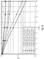
- Fig. 8 shows the performance of the multiple antenna RFID reader shown in figures 5 and 6 with collided non-synchronized RFID tags over Rayleigh channel. The performance is tested using RFID reader having one antenna and two antennas, respectively, and the BLF tolerance follows formula (1).
- the simulation shows that the gain of using single antenna receiver when two RFID tags collide is a round 2,5 dB over the synchronized ones.
- the gain reaches up to 4,5 dB, when two receive antennas are used.
- the performance is improved dramatically for two, three, and four collided RFID tags when the BLF tolerance follows formula (2) as shown in fig. 9 .
- Fig. 10 shows a comparison between the Minimum Mean Square Error (MMSE), Zero Forcing (ZF), and the proposed receiver.
- MMSE Minimum Mean Square Error
- ZF Zero Forcing
- the ZF and MMSE have two receive antennas but the proposed RFID reader is tested with single and two receive antennas.
- the Packet Error Rate (PER) is calculated for two collided RFID tags, however, the strongest RFID tag is selected for all of them.
- the strongest RFID tag is selected for the MMSE and ZF receiver by selecting the ith RFID tag that has max ⁇ H:, i ) ⁇ .
- the inventive RFID reader gives better performance for low SNR (15 dB) because the ZF and MMSE have a noise enhancement and it affects the performance in the low SNR.
- the ZF and MMSE does not give any performance for three and four collided RFID tags as there is no channel estimation for them.
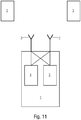
- Fig. 11 shows a scenario in which an inventive RFID reader 1 communicates with two RFID tags 3 in its vicinity. Both RFID tags 3 have an individual BLF for their reply to a query command sent by the RFID reader 1. The different frequencies allows the RFID reader 1 to separate the responses of the RFID tags 3.
- the individual Backscatter Link Frequencies are the result of the increased measurement error for the measured duration of the TRcal signal. This is due to the shape of the TRcal signals within the query command.
- the RFID reader 1 transmits via its two antennas 2 two differently shaped TRcal signals within the query command.
- the individual BLF additionally results from its modified calculation using an individual number of the respective RFID tag 3.
- the RFID reader 1 comprises in the shown embodiment a transmitter component 4 and a receiver component 5 which are both connected to the antennas 2.
- the transmitter component 4 adds the switch signal to the query command and is - in the shown embodiment - responsible for the shape of the TRcal signal comprised by the query command.
- the receiver component 5 allows to switch between the multiple antennas 2 and to identify within the received signals - being the replies from the RFID tags 3 - the signals with the highest energy. With other words: the receiver component 5 differentiates between the replies of the different RFID tags based on their respective frequency.
- the invention refers to a new RFID system (RFID reader and RFID tag) and its components (RFID reader and RFID tag) compatible with UHF EPCglobal class 1 gen 2 standard including the following modifications which are at least partially present in the different embodiments either on both sides (RFID tag and RFID reader) or only on one side (either RFID reader or RFID tag):
- the invention is especially useful for all RFID applications which:
- aspects described in the context of an apparatus it is clear that these aspects also represent a description of the corresponding method. Analogously, aspects described in the context of a method step also represent a description of a corresponding block or item or feature of a corresponding apparatus.
Landscapes
- Engineering & Computer Science (AREA)
- Physics & Mathematics (AREA)
- Health & Medical Sciences (AREA)
- Toxicology (AREA)
- General Physics & Mathematics (AREA)
- Theoretical Computer Science (AREA)
- Electromagnetism (AREA)
- General Health & Medical Sciences (AREA)
- Artificial Intelligence (AREA)
- Computer Vision & Pattern Recognition (AREA)
- Computer Networks & Wireless Communication (AREA)
- Computer Hardware Design (AREA)
- Microelectronics & Electronic Packaging (AREA)
- Near-Field Transmission Systems (AREA)
Claims (10)
- Funkfrequenzidentifikation, RFID,-Tag (3), das dazu konfiguriert ist, mit einem Funkfrequenzidentifikation, RFID,-Leser (1) zu kommunizieren,
wobei das RFID-Tag (3) dazu konfiguriert ist, einen Abfragebefehl von dem RFID-Leser (1) zu empfangen,
wobei das RFID-Tag (3) dazu konfiguriert ist, eine Dauer eines TRcal-Signals zu messen, das in dem Abfragebefehl enthalten ist und
dadurch gekennzeichnet, dass das RFID-Tag (3) dazu konfiguriert ist, eine individuelle Backscatter-Link-Frequenz, BLF, zum Kommunizieren mit dem RFID-Leser (1) basierend auf der gemessenen Dauer des TRcal-Signals und auf einer individuellen Nummer zu bestimmen,
wobei das RFID-Tag (3) dazu konfiguriert ist, die individuelle Nummer durch Erzeugen einer Zufallsnummer zu bestimmen. - RFID-Tag gemäß Anspruch 1,
wobei das RFID-Tag (3) dazu konfiguriert ist, in Abhängigkeit von einem Schaltsignal von dem RFID-Leser (1) entweder eine allgemeine BLF zum Kommunizieren mit dem RFID-Leser (1) basierend auf der gemessenen Dauer des TRcal-Signals oder die individuelle BLF basierend auf der gemessenen Dauer des TRcal-Signals und auf der individuellen Nummer zu bestimmen. - Funkfrequenzidentifikation, RFID,-Leser (1), der dazu konfiguriert ist, mit einem Funkfrequenzidentifikation, RFID,-Tag (3) zu kommunizieren,
wobei der RFID-Leser (1) dazu konfiguriert ist, einen Abfragebefehl an das RFID-Tag (3) zu senden und
wobei der Abfragebefehl das RFID-Tag (3) befähigt, eine Backscatter-Link-Frequenz, BLF, zum Kommunizieren mit dem RFID-Leser (1) zu bestimmen,
wobei der RFID-Leser (1) dazu konfiguriert ist, den Abfragebefehl zu senden, der ein TRcal-Signal mit einer gegebenen Dauer in dem Abfragebefehl enthält,
wobei das TRcal-Signal mit einem Puls mit einer gegebenen Pulsbreite endet und
dadurch gekennzeichnet, dass ein Teil des TRcal-Signals zwischen einem Anfang des TRcal-Signals und einem Anfang des Pulses sich von einem Signal unterscheidet, das einen konstanten Wert aufweist, indem derselbe eine Neigung mit einem gegebenen Wert aufweist, die an dem Anfang des Pulses endet, wodurch die Bestimmung der BLF durch das RFID-Tag erschwert wird. - RFID-Leser (1) gemäß Anspruch 3,
wobei der RFID-Leser (1) dazu konfiguriert ist, ein Schaltsignal zu senden und
wobei das Schaltsignal bestimmt, ob das RFID-Tag (3) entweder eine individuelle BLF basierend auf einer gemessenen Dauer des TRcal-Signals oder eine allgemeine Backscatter-Frequenz basierend auf der gemessenen Dauer des TRcal-Signals bestimmt. - RFID-Leser (1) gemäß einem der Ansprüche 3 bis 4,
wobei der RFID-Leser (1) eine Mehrzahl von Antennen (2) aufweist. - RFID-Leser (1) gemäß Anspruch 5,
wobei der RFID-Leser (1) dazu konfiguriert ist, über die Mehrzahl von Antennen (2) Abfragebefehle zu senden, die unterschiedlich geformte TRcal-Signale aufweisen. - RFID-Leser (1) gemäß Anspruch 5 oder 6,
wobei der RFID-Leser (1) dazu konfiguriert ist, zwischen Antennen (2) der Mehrzahl von Antennen (2) zu schalten. - RFID-Leser (1) gemäß Anspruch 7,
wobei der RFID-Leser (1) dazu konfiguriert ist, zu einer Antenne (2) der Mehrzahl von Antennen (2) zu schalten, basierend auf einer normierten maximalen Energie der Signale, die durch die Mehrzahl von Antennen (2) empfangen werden, mit
- RFID-Leser (1) gemäß einem der Ansprüche 4 bis 8,
wobei der RFID-Leser (1) dazu konfiguriert ist, Signale zu empfangen, und wobei der RFID-Leser (1) dazu konfiguriert ist, innerhalb eines empfangenen Signals basierend auf einer Energie einer Antwort des RFID-Tags (3) zumindest ein RFID-Tag (3) zu identifizieren. - Verfahren zum Erkennen zumindest eines Funkfrequenzidentifikation, RFID,-Tags (3) durch einen Funkfrequenzidentifikation, RFID,-Leser (1), das folgende Schritte aufweist:Senden eines Abfragesignals an das RFID-Tag (3),Bestimmen einer Backscatter-Link-Frequenz, BLF, durch das RFID-Tag (3) undKommunizieren durch das RFID-Tag (3) unter Verwendung der BLF,dadurch gekennzeichnet, dassdas RFID-Tag (3) eine individuelle Backscatter-Link-Frequenz, BLF, als die BLF zum Kommunizieren mit dem RFID-Leser (1) bestimmt, basierend auf einer gemessenen Dauer des TRcal-Signals und auf einer individuellen Nummer, wobei das RFID-Tag (3) die individuelle Nummer durch Erzeugen einer Zufallsnummer bestimmt und/oderder RFID-Leser (1) den Abfragebefehl sendet, der ein TRcal-Signal mit einer gegebenen Dauer in dem Abfragebefehl enthält, wobei das TRcal-Signal mit einem Puls mit einer gegebenen Pulsbreite endet und wobei ein Teil des TRcal-Signals zwischen einem Anfang des TRcal-Signals und einem Anfang des Pulses sich von einem Signal unterscheidet, das einen konstanten Wert aufweist, indem derselbe eine Neigung mit einem gegebenen Wert aufweist, die an dem Anfang des Pulses endet, wodurch die Bestimmung der Backscatter-Link-Frequenz, BLF, durch das RFID-Tag (3) erschwert wird.
Priority Applications (4)
| Application Number | Priority Date | Filing Date | Title |
|---|---|---|---|
| ES16155475T ES2841910T3 (es) | 2016-02-12 | 2016-02-12 | Etiqueta RFID y lector RFID |
| EP16155475.3A EP3206166B1 (de) | 2016-02-12 | 2016-02-12 | Rfid-etikett und rfid-leser |
| PCT/EP2017/052697 WO2017137412A1 (en) | 2016-02-12 | 2017-02-08 | Rfid tag and rfid reader |
| US16/059,741 US10474944B2 (en) | 2016-02-12 | 2018-08-09 | RFID tag and RFID reader |
Applications Claiming Priority (1)
| Application Number | Priority Date | Filing Date | Title |
|---|---|---|---|
| EP16155475.3A EP3206166B1 (de) | 2016-02-12 | 2016-02-12 | Rfid-etikett und rfid-leser |
Publications (2)
| Publication Number | Publication Date |
|---|---|
| EP3206166A1 EP3206166A1 (de) | 2017-08-16 |
| EP3206166B1 true EP3206166B1 (de) | 2020-10-28 |
Family
ID=55353120
Family Applications (1)
| Application Number | Title | Priority Date | Filing Date |
|---|---|---|---|
| EP16155475.3A Active EP3206166B1 (de) | 2016-02-12 | 2016-02-12 | Rfid-etikett und rfid-leser |
Country Status (4)
| Country | Link |
|---|---|
| US (1) | US10474944B2 (de) |
| EP (1) | EP3206166B1 (de) |
| ES (1) | ES2841910T3 (de) |
| WO (1) | WO2017137412A1 (de) |
Cited By (1)
| Publication number | Priority date | Publication date | Assignee | Title |
|---|---|---|---|---|
| EP4528581A4 (de) * | 2022-05-24 | 2025-09-03 | Vivo Mobile Communication Co Ltd | Rückstreusignalübertragungsverfahren und -vorrichtung, kommunikationsvorrichtung und lesbares speichermedium |
Families Citing this family (3)
| Publication number | Priority date | Publication date | Assignee | Title |
|---|---|---|---|---|
| CN106330266B (zh) * | 2016-08-16 | 2018-10-16 | 武汉万集信息技术有限公司 | 一种读写器设备及读写器和标签通信的时序优化方法 |
| WO2024016201A1 (en) * | 2022-07-20 | 2024-01-25 | Qualcomm Incorporated | Group-based access of passive rfid tags |
| CN117669607A (zh) * | 2022-08-10 | 2024-03-08 | 上海华为技术有限公司 | 一种rfid多标签读写识别方法及相关设备 |
Family Cites Families (3)
| Publication number | Priority date | Publication date | Assignee | Title |
|---|---|---|---|---|
| US7246751B2 (en) | 2004-10-26 | 2007-07-24 | Impinj, Inc. | RFID tags calibrating backscattering period also for non-integer divide ratios |
| US8193912B1 (en) | 2008-03-13 | 2012-06-05 | Impinj, Inc. | RFID tag dynamically adjusting clock frequency |
| KR101268542B1 (ko) | 2009-12-21 | 2013-05-28 | 한국전자통신연구원 | 다수의 rfid 태그를 인식하기 위한 시스템 및 방법 |
-
2016
- 2016-02-12 EP EP16155475.3A patent/EP3206166B1/de active Active
- 2016-02-12 ES ES16155475T patent/ES2841910T3/es active Active
-
2017
- 2017-02-08 WO PCT/EP2017/052697 patent/WO2017137412A1/en not_active Ceased
-
2018
- 2018-08-09 US US16/059,741 patent/US10474944B2/en active Active
Non-Patent Citations (1)
| Title |
|---|
| None * |
Cited By (1)
| Publication number | Priority date | Publication date | Assignee | Title |
|---|---|---|---|---|
| EP4528581A4 (de) * | 2022-05-24 | 2025-09-03 | Vivo Mobile Communication Co Ltd | Rückstreusignalübertragungsverfahren und -vorrichtung, kommunikationsvorrichtung und lesbares speichermedium |
Also Published As
| Publication number | Publication date |
|---|---|
| ES2841910T3 (es) | 2021-07-12 |
| US10474944B2 (en) | 2019-11-12 |
| EP3206166A1 (de) | 2017-08-16 |
| US20180349753A1 (en) | 2018-12-06 |
| WO2017137412A1 (en) | 2017-08-17 |
Similar Documents
| Publication | Publication Date | Title |
|---|---|---|
| US10474944B2 (en) | RFID tag and RFID reader | |
| US9881187B2 (en) | RFID reader and method for adjusting a frame length of an RFID system comprising an RFID reader | |
| Bletsas et al. | Single-antenna coherent detection of collided FM0 RFID signals | |
| US20080048833A1 (en) | Rfid reader system aided by rf power of measurement | |
| KR101589526B1 (ko) | 다중 패킷 수신이 가능한 rfid 시스템의 태그 충돌 방지 방법 및 태그 인식 장치, 및 시스템 | |
| US20070164851A1 (en) | Rfid reader q-parameter aided by rf power measurement | |
| Khasgiwale et al. | Extracting information from tag collisions | |
| US20090289767A1 (en) | Interrogating device, rfid interrogator, and rfid interrogating method | |
| Su et al. | A collision-tolerant-based anti-collision algorithm for large scale RFID system | |
| CN109313252A (zh) | 用于定位的通信设备和方法 | |
| US20070071036A1 (en) | Method and apparatus for preamble synchronization in wireless radio frequency identification (RFID) systems | |
| El-Hadidy et al. | A novel collision avoidance MAC protocol for multi-tag UWB chipless RFID systems based on Notch Position Modulation | |
| EP1911234A2 (de) | Verfahren und vorrichtung zur datensignalverarbeitung in drahtlosen rfid-systemen | |
| Bratuž et al. | Resolving collision in EPCglobal Class-1 Gen-2 system by utilizing the preamble | |
| Benbaghdad et al. | Toward a new PHY layer scheme for decoding tags collision signal in UHF RFID system | |
| Angerer et al. | Single antenna physical layer collision recover receivers for RFID readers | |
| KR20150054541A (ko) | Rfid 리더기의 수신 장치 및 수신 방법 | |
| Kaitovic et al. | RFID reader with multi antenna physical layer collision recovery receivers | |
| Salah et al. | Multi-antenna UHF RFID reader utilizing stimulated rate tolerance | |
| Biao et al. | Trends and brief comments on anti-collision techniques in radio frequency identification system | |
| Duan et al. | Channel estimation for recovery of UHF RFID tag collision on physical layer | |
| Salah et al. | Alleviating slot collisions in UHF RFID systems | |
| Ahmed et al. | Backwards compatible improvement of the EPCglobal class 1 gen 2 standard | |
| Salah et al. | FFT based rate estimation for UHF RFID systems | |
| Kimionis et al. | Inventory time reduction in Gen2 with single-antenna separation of FM0 RFID signals |
Legal Events
| Date | Code | Title | Description |
|---|---|---|---|
| PUAI | Public reference made under article 153(3) epc to a published international application that has entered the european phase |
Free format text: ORIGINAL CODE: 0009012 |
|
| STAA | Information on the status of an ep patent application or granted ep patent |
Free format text: STATUS: THE APPLICATION HAS BEEN PUBLISHED |
|
| AK | Designated contracting states |
Kind code of ref document: A1 Designated state(s): AL AT BE BG CH CY CZ DE DK EE ES FI FR GB GR HR HU IE IS IT LI LT LU LV MC MK MT NL NO PL PT RO RS SE SI SK SM TR |
|
| AX | Request for extension of the european patent |
Extension state: BA ME |
|
| STAA | Information on the status of an ep patent application or granted ep patent |
Free format text: STATUS: REQUEST FOR EXAMINATION WAS MADE |
|
| 17P | Request for examination filed |
Effective date: 20180216 |
|
| RBV | Designated contracting states (corrected) |
Designated state(s): AL AT BE BG CH CY CZ DE DK EE ES FI FR GB GR HR HU IE IS IT LI LT LU LV MC MK MT NL NO PL PT RO RS SE SI SK SM TR |
|
| STAA | Information on the status of an ep patent application or granted ep patent |
Free format text: STATUS: EXAMINATION IS IN PROGRESS |
|
| 17Q | First examination report despatched |
Effective date: 20180822 |
|
| GRAP | Despatch of communication of intention to grant a patent |
Free format text: ORIGINAL CODE: EPIDOSNIGR1 |
|
| STAA | Information on the status of an ep patent application or granted ep patent |
Free format text: STATUS: GRANT OF PATENT IS INTENDED |
|
| INTG | Intention to grant announced |
Effective date: 20200508 |
|
| GRAS | Grant fee paid |
Free format text: ORIGINAL CODE: EPIDOSNIGR3 |
|
| GRAA | (expected) grant |
Free format text: ORIGINAL CODE: 0009210 |
|
| STAA | Information on the status of an ep patent application or granted ep patent |
Free format text: STATUS: THE PATENT HAS BEEN GRANTED |
|
| AK | Designated contracting states |
Kind code of ref document: B1 Designated state(s): AL AT BE BG CH CY CZ DE DK EE ES FI FR GB GR HR HU IE IS IT LI LT LU LV MC MK MT NL NO PL PT RO RS SE SI SK SM TR |
|
| REG | Reference to a national code |
Ref country code: GB Ref legal event code: FG4D |
|
| REG | Reference to a national code |
Ref country code: CH Ref legal event code: EP |
|
| REG | Reference to a national code |
Ref country code: AT Ref legal event code: REF Ref document number: 1328956 Country of ref document: AT Kind code of ref document: T Effective date: 20201115 |
|
| REG | Reference to a national code |
Ref country code: DE Ref legal event code: R096 Ref document number: 602016046552 Country of ref document: DE |
|
| REG | Reference to a national code |
Ref country code: IE Ref legal event code: FG4D |
|
| REG | Reference to a national code |
Ref country code: AT Ref legal event code: MK05 Ref document number: 1328956 Country of ref document: AT Kind code of ref document: T Effective date: 20201028 |
|
| REG | Reference to a national code |
Ref country code: NL Ref legal event code: MP Effective date: 20201028 |
|
| PG25 | Lapsed in a contracting state [announced via postgrant information from national office to epo] |
Ref country code: NL Free format text: LAPSE BECAUSE OF FAILURE TO SUBMIT A TRANSLATION OF THE DESCRIPTION OR TO PAY THE FEE WITHIN THE PRESCRIBED TIME-LIMIT Effective date: 20201028 Ref country code: NO Free format text: LAPSE BECAUSE OF FAILURE TO SUBMIT A TRANSLATION OF THE DESCRIPTION OR TO PAY THE FEE WITHIN THE PRESCRIBED TIME-LIMIT Effective date: 20210128 Ref country code: FI Free format text: LAPSE BECAUSE OF FAILURE TO SUBMIT A TRANSLATION OF THE DESCRIPTION OR TO PAY THE FEE WITHIN THE PRESCRIBED TIME-LIMIT Effective date: 20201028 Ref country code: RS Free format text: LAPSE BECAUSE OF FAILURE TO SUBMIT A TRANSLATION OF THE DESCRIPTION OR TO PAY THE FEE WITHIN THE PRESCRIBED TIME-LIMIT Effective date: 20201028 Ref country code: PT Free format text: LAPSE BECAUSE OF FAILURE TO SUBMIT A TRANSLATION OF THE DESCRIPTION OR TO PAY THE FEE WITHIN THE PRESCRIBED TIME-LIMIT Effective date: 20210301 Ref country code: GR Free format text: LAPSE BECAUSE OF FAILURE TO SUBMIT A TRANSLATION OF THE DESCRIPTION OR TO PAY THE FEE WITHIN THE PRESCRIBED TIME-LIMIT Effective date: 20210129 |
|
| REG | Reference to a national code |
Ref country code: LT Ref legal event code: MG4D |
|
| PG25 | Lapsed in a contracting state [announced via postgrant information from national office to epo] |
Ref country code: AT Free format text: LAPSE BECAUSE OF FAILURE TO SUBMIT A TRANSLATION OF THE DESCRIPTION OR TO PAY THE FEE WITHIN THE PRESCRIBED TIME-LIMIT Effective date: 20201028 Ref country code: BG Free format text: LAPSE BECAUSE OF FAILURE TO SUBMIT A TRANSLATION OF THE DESCRIPTION OR TO PAY THE FEE WITHIN THE PRESCRIBED TIME-LIMIT Effective date: 20210128 Ref country code: LV Free format text: LAPSE BECAUSE OF FAILURE TO SUBMIT A TRANSLATION OF THE DESCRIPTION OR TO PAY THE FEE WITHIN THE PRESCRIBED TIME-LIMIT Effective date: 20201028 Ref country code: IS Free format text: LAPSE BECAUSE OF FAILURE TO SUBMIT A TRANSLATION OF THE DESCRIPTION OR TO PAY THE FEE WITHIN THE PRESCRIBED TIME-LIMIT Effective date: 20210228 Ref country code: SE Free format text: LAPSE BECAUSE OF FAILURE TO SUBMIT A TRANSLATION OF THE DESCRIPTION OR TO PAY THE FEE WITHIN THE PRESCRIBED TIME-LIMIT Effective date: 20201028 Ref country code: PL Free format text: LAPSE BECAUSE OF FAILURE TO SUBMIT A TRANSLATION OF THE DESCRIPTION OR TO PAY THE FEE WITHIN THE PRESCRIBED TIME-LIMIT Effective date: 20201028 |
|
| PG25 | Lapsed in a contracting state [announced via postgrant information from national office to epo] |
Ref country code: HR Free format text: LAPSE BECAUSE OF FAILURE TO SUBMIT A TRANSLATION OF THE DESCRIPTION OR TO PAY THE FEE WITHIN THE PRESCRIBED TIME-LIMIT Effective date: 20201028 |
|
| REG | Reference to a national code |
Ref country code: ES Ref legal event code: FG2A Ref document number: 2841910 Country of ref document: ES Kind code of ref document: T3 Effective date: 20210712 |
|
| REG | Reference to a national code |
Ref country code: DE Ref legal event code: R097 Ref document number: 602016046552 Country of ref document: DE |
|
| PG25 | Lapsed in a contracting state [announced via postgrant information from national office to epo] |
Ref country code: CZ Free format text: LAPSE BECAUSE OF FAILURE TO SUBMIT A TRANSLATION OF THE DESCRIPTION OR TO PAY THE FEE WITHIN THE PRESCRIBED TIME-LIMIT Effective date: 20201028 Ref country code: EE Free format text: LAPSE BECAUSE OF FAILURE TO SUBMIT A TRANSLATION OF THE DESCRIPTION OR TO PAY THE FEE WITHIN THE PRESCRIBED TIME-LIMIT Effective date: 20201028 Ref country code: LT Free format text: LAPSE BECAUSE OF FAILURE TO SUBMIT A TRANSLATION OF THE DESCRIPTION OR TO PAY THE FEE WITHIN THE PRESCRIBED TIME-LIMIT Effective date: 20201028 Ref country code: SM Free format text: LAPSE BECAUSE OF FAILURE TO SUBMIT A TRANSLATION OF THE DESCRIPTION OR TO PAY THE FEE WITHIN THE PRESCRIBED TIME-LIMIT Effective date: 20201028 Ref country code: RO Free format text: LAPSE BECAUSE OF FAILURE TO SUBMIT A TRANSLATION OF THE DESCRIPTION OR TO PAY THE FEE WITHIN THE PRESCRIBED TIME-LIMIT Effective date: 20201028 Ref country code: SK Free format text: LAPSE BECAUSE OF FAILURE TO SUBMIT A TRANSLATION OF THE DESCRIPTION OR TO PAY THE FEE WITHIN THE PRESCRIBED TIME-LIMIT Effective date: 20201028 |
|
| PG25 | Lapsed in a contracting state [announced via postgrant information from national office to epo] |
Ref country code: DK Free format text: LAPSE BECAUSE OF FAILURE TO SUBMIT A TRANSLATION OF THE DESCRIPTION OR TO PAY THE FEE WITHIN THE PRESCRIBED TIME-LIMIT Effective date: 20201028 |
|
| PLBE | No opposition filed within time limit |
Free format text: ORIGINAL CODE: 0009261 |
|
| STAA | Information on the status of an ep patent application or granted ep patent |
Free format text: STATUS: NO OPPOSITION FILED WITHIN TIME LIMIT |
|
| PG25 | Lapsed in a contracting state [announced via postgrant information from national office to epo] |
Ref country code: MC Free format text: LAPSE BECAUSE OF FAILURE TO SUBMIT A TRANSLATION OF THE DESCRIPTION OR TO PAY THE FEE WITHIN THE PRESCRIBED TIME-LIMIT Effective date: 20201028 |
|
| 26N | No opposition filed |
Effective date: 20210729 |
|
| REG | Reference to a national code |
Ref country code: BE Ref legal event code: MM Effective date: 20210228 |
|
| PG25 | Lapsed in a contracting state [announced via postgrant information from national office to epo] |
Ref country code: CH Free format text: LAPSE BECAUSE OF NON-PAYMENT OF DUE FEES Effective date: 20210228 Ref country code: AL Free format text: LAPSE BECAUSE OF FAILURE TO SUBMIT A TRANSLATION OF THE DESCRIPTION OR TO PAY THE FEE WITHIN THE PRESCRIBED TIME-LIMIT Effective date: 20201028 Ref country code: LI Free format text: LAPSE BECAUSE OF NON-PAYMENT OF DUE FEES Effective date: 20210228 Ref country code: LU Free format text: LAPSE BECAUSE OF NON-PAYMENT OF DUE FEES Effective date: 20210212 |
|
| PG25 | Lapsed in a contracting state [announced via postgrant information from national office to epo] |
Ref country code: SI Free format text: LAPSE BECAUSE OF FAILURE TO SUBMIT A TRANSLATION OF THE DESCRIPTION OR TO PAY THE FEE WITHIN THE PRESCRIBED TIME-LIMIT Effective date: 20201028 |
|
| PG25 | Lapsed in a contracting state [announced via postgrant information from national office to epo] |
Ref country code: IE Free format text: LAPSE BECAUSE OF NON-PAYMENT OF DUE FEES Effective date: 20210212 |
|
| PG25 | Lapsed in a contracting state [announced via postgrant information from national office to epo] |
Ref country code: IS Free format text: LAPSE BECAUSE OF FAILURE TO SUBMIT A TRANSLATION OF THE DESCRIPTION OR TO PAY THE FEE WITHIN THE PRESCRIBED TIME-LIMIT Effective date: 20210228 |
|
| PG25 | Lapsed in a contracting state [announced via postgrant information from national office to epo] |
Ref country code: BE Free format text: LAPSE BECAUSE OF NON-PAYMENT OF DUE FEES Effective date: 20210228 |
|
| PG25 | Lapsed in a contracting state [announced via postgrant information from national office to epo] |
Ref country code: HU Free format text: LAPSE BECAUSE OF FAILURE TO SUBMIT A TRANSLATION OF THE DESCRIPTION OR TO PAY THE FEE WITHIN THE PRESCRIBED TIME-LIMIT; INVALID AB INITIO Effective date: 20160212 |
|
| PG25 | Lapsed in a contracting state [announced via postgrant information from national office to epo] |
Ref country code: CY Free format text: LAPSE BECAUSE OF FAILURE TO SUBMIT A TRANSLATION OF THE DESCRIPTION OR TO PAY THE FEE WITHIN THE PRESCRIBED TIME-LIMIT Effective date: 20201028 |
|
| PG25 | Lapsed in a contracting state [announced via postgrant information from national office to epo] |
Ref country code: MK Free format text: LAPSE BECAUSE OF FAILURE TO SUBMIT A TRANSLATION OF THE DESCRIPTION OR TO PAY THE FEE WITHIN THE PRESCRIBED TIME-LIMIT Effective date: 20201028 |
|
| PG25 | Lapsed in a contracting state [announced via postgrant information from national office to epo] |
Ref country code: MT Free format text: LAPSE BECAUSE OF FAILURE TO SUBMIT A TRANSLATION OF THE DESCRIPTION OR TO PAY THE FEE WITHIN THE PRESCRIBED TIME-LIMIT Effective date: 20201028 |
|
| P01 | Opt-out of the competence of the unified patent court (upc) registered |
Free format text: CASE NUMBER: UPC_APP_326365/2023 Effective date: 20230524 |
|
| PG25 | Lapsed in a contracting state [announced via postgrant information from national office to epo] |
Ref country code: TR Free format text: LAPSE BECAUSE OF FAILURE TO SUBMIT A TRANSLATION OF THE DESCRIPTION OR TO PAY THE FEE WITHIN THE PRESCRIBED TIME-LIMIT Effective date: 20201028 |
|
| PGFP | Annual fee paid to national office [announced via postgrant information from national office to epo] |
Ref country code: GB Payment date: 20260219 Year of fee payment: 11 |
|
| PGFP | Annual fee paid to national office [announced via postgrant information from national office to epo] |
Ref country code: ES Payment date: 20260319 Year of fee payment: 11 |
|
| PGFP | Annual fee paid to national office [announced via postgrant information from national office to epo] |
Ref country code: DE Payment date: 20260217 Year of fee payment: 11 |
|
| PGFP | Annual fee paid to national office [announced via postgrant information from national office to epo] |
Ref country code: IT Payment date: 20260227 Year of fee payment: 11 |
|
| PGFP | Annual fee paid to national office [announced via postgrant information from national office to epo] |
Ref country code: FR Payment date: 20260223 Year of fee payment: 11 |