EP3206008B1 - An automotive testing system, method and computer program product - Google Patents
An automotive testing system, method and computer program product Download PDFInfo
- Publication number
- EP3206008B1 EP3206008B1 EP16155078.5A EP16155078A EP3206008B1 EP 3206008 B1 EP3206008 B1 EP 3206008B1 EP 16155078 A EP16155078 A EP 16155078A EP 3206008 B1 EP3206008 B1 EP 3206008B1
- Authority
- EP
- European Patent Office
- Prior art keywords
- sensor
- data
- unit
- synthetic
- camera
- Prior art date
- Legal status (The legal status is an assumption and is not a legal conclusion. Google has not performed a legal analysis and makes no representation as to the accuracy of the status listed.)
- Active
Links
- 238000012360 testing method Methods 0.000 title claims description 54
- 238000004590 computer program Methods 0.000 title claims description 6
- 238000000034 method Methods 0.000 title description 13
- 238000012545 processing Methods 0.000 claims description 51
- 238000007781 pre-processing Methods 0.000 claims description 23
- 230000005540 biological transmission Effects 0.000 claims description 11
- 238000001514 detection method Methods 0.000 claims description 4
- 238000004088 simulation Methods 0.000 description 4
- 230000000694 effects Effects 0.000 description 3
- 230000003287 optical effect Effects 0.000 description 3
- 230000003993 interaction Effects 0.000 description 2
- 238000012805 post-processing Methods 0.000 description 2
- 230000001133 acceleration Effects 0.000 description 1
- 238000006243 chemical reaction Methods 0.000 description 1
- 238000011156 evaluation Methods 0.000 description 1
- 238000002474 experimental method Methods 0.000 description 1
- 230000004044 response Effects 0.000 description 1
- 230000002194 synthesizing effect Effects 0.000 description 1
- 238000010998 test method Methods 0.000 description 1
- 230000000007 visual effect Effects 0.000 description 1
Images


Classifications
-
- G—PHYSICS
- G01—MEASURING; TESTING
- G01M—TESTING STATIC OR DYNAMIC BALANCE OF MACHINES OR STRUCTURES; TESTING OF STRUCTURES OR APPARATUS, NOT OTHERWISE PROVIDED FOR
- G01M17/00—Testing of vehicles
- G01M17/007—Wheeled or endless-tracked vehicles
Definitions
- the invention relates to an automotive testing system, comprising a data processing unit provided with a data input port for receiving sensor input data and a data output port for transmitting processed data, further comprising a data acquisition unit forwarding sensor input data to said data processing unit, the data acquisition unit including a sensor unit having a sensor system and an electronic system for capturing sensor data.
- Automotive testing systems are known for the purpose of testing data acquisition units and data processing units processing sensor input data generated by said data acquisition units, thereby reducing expensive testing equipment and testing time in realistic traffic circumstances.
- Data acquisition units can be provided with a camera unit having an optic system and an electronic system for capturing image data.
- an optic image is generated on a display to be captured by the camera unit.
- various traffic situations including road traffic and weather circumstances are shown to test the functionality of the camera unit and the data processing unit processing the image data captured by the camera unit.
- the automotive testing system further comprises a synthetic sensor data generator transmitting synthetic sensor data to the electronic system of the sensor unit.
- the optic system of the camera unit is functionally simulated so that testing data can be represented more realistically to the electronic system of the camera unit.
- side effects introduced in the optical path of the testing system can be avoided, while, on the other hand, real life optic phenomena that are not visible on a display might now be included in the synthetic sensor data mimicking the optical steps performed in the camera unit.
- Vehicle driveability evaluation system discloses a system for generating driveability signal for a setup in which a real car engine is embedded in a driving simulator. Sensor data of the engine is processed with simulation of external conditions and vehicle dynamics. The output is used to control an artificial load (dynamic dynamometer) for the engine and for synthesizing images and physical feedback such as acceleration for the driver.
- an artificial load dynamic dynamometer
- the document KR-100709401B discloses a hardware in the loop simulation apparatus and a test method thereof for lane departure warning systems, whereby images are displayed on a screen.
- the invention is at least partly based on the insight that a display inherently is limited in representing realistic optic circumstances thereby also limiting the performance and/or reliability of the automotive testing system. Further, display features are subjected to bias so that test results of the system are vulnerable to reproducibility issues. According to an aspect of the invention, such disadvantageous effects are circumvented by generating synthetic sensor data replacing the real image data as well as by transmitting these synthetic sensor data to the electronic system of the sensor unit rather than projecting these to the sensor unit via a display.
- synthetic sensor data is to be understood as data that has been generated electronically by simulating data that is normally generated by the respective sensor system.
- the invention also relates to a method.
- a computer program product may comprise a set of computer executable instructions stored on a data carrier, such as a flash memory, a CD or a DVD.
- the set of computer executable instructions which allow a programmable computer to carry out the method as defined above, may also be available for downloading from a remote server, for example via the Internet, e.g. as an app.
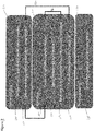
- Figure 1 shows a schematic view of an automotive testing system 1 according to the invention.
- the system comprises a data processing unit 2, a data acquisition unit 3 and a synthetic sensor data generator 4.
- the data processing unit 2 is provided with a data input port 11 for receiving sensor input data and a data output port 12 for transmitting processed data PD, e.g. for the purpose of feeding a control unit for generating control data based on the processed data transmitted by the processing unit 2.
- the processing unit 2 further comprises an additional data input port 13, e.g. for receiving further input data, e.g. radar data.
- the data acquisition unit 3 is arranged for forwarding sensor input data to said data processing unit 2, via the data input port 11 of the data processing unit 2.
- the data acquisition unit 3 includes a sensor unit 21 having a sensor system 22 and an electronic system 23 for capturing sensor data.
- the sensor unit 21 is implemented as a camera unit, wherein the sensor system 22 is an optic system and wherein the sensor data are image data.
- the synthetic sensor data generator 4 of the automotive testing system 1 is arranged for generating and transmitting synthetic sensor data also referred to as electronic image pixel signals IPS to the electronic system 23 of the camera unit 21.
- the image simulating generator 4 is connected to the electronic system 23 of the camera unit 21 via a wired transmission channel 24.
- the image pixel signals IPS can be transmitted in another way, e.g. via a wireless transmission channel.
- the electronic system 23 of the camera unit 21 includes two modules, e.g. a pre-processing module 25 and a digital signal processing unit DSP 26 arranged in series such that the pre-processing module 25 processes raw image data converting them into pre-processed image data PPI while the digital signal processing unit DSP 26 performs further processing on the pre-processed data PPI and then transmits the processed data as sensor input data SID to the data input port 11 of the data processing unit 2.
- the pre-processing module 25 might be arranged for removing noise from image data while the digital signal processing unit may be arranged for identifying object information from the image data.
- the pre-processing module 25 transmits status information 30 of the pre-processing module 25 and the optic system 22 towards the digital signal processing unit DSP 26, as metadata.
- the optic system 22 of the camera unit 21 typically includes a lens configuration 27 and an image optic sensor 28. Further, the optic system 22 may include other components as well such as a shutter.
- the image optic sensor 28 can be implemented as a CCD or CMOS sensor converting an optic signals OS received from an optic image OI into electronic pixel signals EPS representing the optic image OI as electronic signals.
- the image optic sensor 28 may at least partially be integrated with the pre-processing module 25.
- the image optic sensor 28 is connected to the electronic system 23 via a sensor data channel 29 to transmit the electronic pixel signals EPS converted from the optic signals OS towards the electronic system 23 for processing. Then, an optic image OI is captured by converting optic signals OS into electronic pixel signals EPS and processing said electronic pixel signals EPS by the electronic system 23.
- the pre-processing module 25 transmits pre-processed data PPI and status information 30 towards the digital signal processing unit DSP 26. Then, the digital signal processing unit DSP 26 forwards sensor input data SID to the data input port 11 data processing unit 2 and image enhancements requests and/or commands 31 back to the pre-processing module 25.
- an image generator generating an optic image OI on a display arranged before the camera unit 21.
- the image generator typically generates a sequence of images forming a video showing realistic traffic situations to simulate common real life traffic circumstances for testing the performance of the camera unit 21 and further systems such as the data processing unit 2 of the automotive testing system 1.
- the electronic system 23 of the camera unit 21 receives synthetic sensor data also referred to as electronic image pixel signals IPS generated by the synthetic sensor data generator 4 of the automotive testing system 1, thus simulating image data that usually is captured by the camera system using the optic system 22.
- the electronic pixel signals EPS provided by the image optic sensor 28 no longer forms a basis for the sensor input data SID that is transmitted from the digital signal processor DSP 26 to the data input port 11 of the data processing unit 2.
- the pre-processing module 25 transmits neither pre-processed data PPI nor status information 30 towards the digital signal processing unit DSP 26. Said transmission can be stopped e.g. by physically disconnecting respective transmission channels or by functionally terminating said transmission actions, using software.
- pre-processed data PPI and/or status information 30 towards the digital signal processing unit DSP 26 can also be disabled in another way e.g. by deactivating the image optic sensor 28 and/or by removing disabling the sensor data channel 29.
- an optic image is captured by generating synthetic image sensor data or electronic image pixel signals IPS simulating in the electronic domain the functionality of the optic system 22 of the camera unit 21 including propagation of the optic signal OS through the lens system 27 and conversion into electronic pixel signals EPS using the image optic sensor 28.
- image data captured by the camera unit 21 are based on the electronic image pixel or data signals transmitted to the electronic system 23 of the camera unit 21.
- the optic part of the testing environment is effectively simulated thus removing artefacts that might be introduced in said optic part during testing but are not present in real life circumstances.
- artefacts might be generated when generating the optic image OI using RGB light generating elements.
- real life optic phenomena that are not visible in the generated optic image OI, such as infrared interaction, might now be included in the image pixel signals IPS mimicking the optical steps performed in the camera unit 21.
- the image optic sensor 28 may even be removed from the camera unit 21.
- other functionality of the camera unit 21 remains in operation, e.g. including controlling operations of the lens system and/or shutter operation.
- status information of the pre-processing module 25 and/or optic system 22 e.g. regarding the lens system 27 and other optic components is forwarded to the synthetic sensor data generator 4, as status information 38, so that the image pixel signals IPS may take into account optic propagation behaviour of the simulated optic signal OS in the optic system 22 and other processing effects in the pre-processing module 25.
- the synthetic sensor data or electronic image pixel signals IPS might represent pixel data that has already been processed in a pre-processing module 25 of the electronic system 23. Then, the image pixel signals IPS is transmitted to the digital signal processing unit DSP 26 of the camera unit 21.
- the data transmission channel 24 interconnects the synthetic sensor data generator 4 and the digital signal processing unit DSP 26 so that the image pixel signals IPS is transmitted to said digital signal processing unit DSP 26. Then, the usual electronic interaction between the pre-processing module 25 and the digital signal processing unit DSP 26 is interrupted.
- the digital signal processing unit DSP 26 receives image pixel signals IPS and synthetic status information 30' of the pre-processing module 25, both from the synthetic sensor data generator 4. Both the image data and status data usually transmitted by the pre-processing module 25 is now simulated by the synthetic sensor data generator 4. Also, the digital signal processing unit DSP 26 now transmits the image enhancements requests and/or commands 31' to the synthetic sensor data generator 4, so that said generator 4 may include such information when generating the synthetic image and status data.
- the image pixel signals IPS might be transmitted to the electronic system 23 in another format, e.g. as raw pixel data that is usually generated by the image optic sensor 28. Then, the image pixel signals IPS may be transmitted to the pre-processing module 25 or to another module of the electronic system 23 of the camera unit 21.
- the sensor unit is implemented as a unit receiving other sensor signals such as laser signals, infrared signals, radar signals, acoustic signals, ultrasonic signals, pressure signals or electronic signals received in a wired or wireless way and representing any type of measured physical signals associated with automotive conditions or parameters.
- the signals may relate to automotive conditions or parameters of a vehicle in which the sensor unit is mounted or automotive conditions or parameters of other vehicles forwarding such signals to the sensor unit.
- the automotive testing system may include a multiple number of acquisition units wherein sensor data is simulated using synthetic sensor data.
- a process of generating sensor data in the sensor unit can be simulated in the electronic domain in a manner that is more realistic than simulating the parameter to be sensed in the parameter domain, i.e. in the visual, electromagnetic, acoustic, ultra-acoustic or other physical domain.
- Figure 2 shows a flow chart of an embodiment of a method according to the invention.
- the method is used for automotive testing, and comprises a step of acquiring 110 sensor input data, and a step of processing 120 said sensor input data, wherein the step of acquiring 110 sensor input data includes capturing sensor data using a sensor unit having a sensor system and an electronic system, and wherein the step of acquiring 110 sensor input data further includes transmitting synthetic sensor data from a synthetic sensor data generator to the electronic system of the sensor unit.
- the method of automotive testing can be facilitated using dedicated hardware structures, such as computer servers. Otherwise, the method can also at least partially be performed using a computer program product comprising instructions for causing a processor of a computer system to facilitate automotive testing. All (sub)steps can in principle be performed on a single processor. However, it is noted that at least one step can be performed on a separate processor.
- a processor can be loaded with a specific software module.
- Dedicated software modules can be provided, e.g. from the Internet.
- Fig. 3 shows a flow chart of a second embodiment of a method according to the invention.
- the method includes three modules, e.g. a pre-processing module 210, a run-time module 220 and a post-processing module 230.
- the pre-processing module 210 includes a step of configuring 240 optics and imager in a simulation model to create a simulation environment. Further, the pre-processing module 210 includes a step of defining 250 test automation parameters using scrips in order to define test cases for testing the data acquisition unit.
- the run-time module 220 includes four steps, viz. a step of generating 260 synthetic camera images using the synthetic sensor data generator, a step of injecting 270 images into an automotive ECU, e.g.
- the post-processing module 230 includes a step of generating 295 a report on performance scores obtained from the calculated performance scores.
- the run-time module 220 includes a first feedback loop FB1 so that a sequence of the generating step 260, the injecting step 270 and the retrieving step 280 is repeatedly performed simulating the test cases defined in the defining step 250 of the pre-processing module 210. Further, a second feedback loop FB2 is provided such the defining step 250 is repeated after calculating 290 the performance scores to facilitate additional testing experiments based on test results. It is noted that various alternative embodiments can be implemented, e.g. by including further feedback loops and/or by integrating test results of other test equipment.
- the electronic system 23 of the sensor unit 21 may include more or less units for processing sensor data.
- the sensor unit 21 may be implemented without a digital signal processing unit DSP 26 or with an additional processing unit for processing intermediate sensor data.
Description
- The invention relates to an automotive testing system, comprising a data processing unit provided with a data input port for receiving sensor input data and a data output port for transmitting processed data, further comprising a data acquisition unit forwarding sensor input data to said data processing unit, the data acquisition unit including a sensor unit having a sensor system and an electronic system for capturing sensor data.
- Automotive testing systems are known for the purpose of testing data acquisition units and data processing units processing sensor input data generated by said data acquisition units, thereby reducing expensive testing equipment and testing time in realistic traffic circumstances. Data acquisition units can be provided with a camera unit having an optic system and an electronic system for capturing image data.
- When testing camera units, e.g. used for dedicated automotive functionality such as variable cruise control, collision avoiding systems, pedestrian detection etc, an optic image is generated on a display to be captured by the camera unit. On the display, various traffic situations including road traffic and weather circumstances are shown to test the functionality of the camera unit and the data processing unit processing the image data captured by the camera unit.
- It is an object of the invention to provide an automotive testing system according to the preamble that enables testing even more realistic circumstances. Thereto, according to the invention, the automotive testing system further comprises a synthetic sensor data generator transmitting synthetic sensor data to the electronic system of the sensor unit.
- By using a synthetic sensor data generator instead of a display, the optic system of the camera unit is functionally simulated so that testing data can be represented more realistically to the electronic system of the camera unit. On the one hand, side effects introduced in the optical path of the testing system can be avoided, while, on the other hand, real life optic phenomena that are not visible on a display might now be included in the synthetic sensor data mimicking the optical steps performed in the camera unit.
- The document
US 5,986,545 - Sanada et al. "Vehicle driveability evaluation system" discloses a system for generating driveability signal for a setup in which a real car engine is embedded in a driving simulator. Sensor data of the engine is processed with simulation of external conditions and vehicle dynamics. The output is used to control an artificial load (dynamic dynamometer) for the engine and for synthesizing images and physical feedback such as acceleration for the driver. - The document
KR-100709401B - The invention is at least partly based on the insight that a display inherently is limited in representing realistic optic circumstances thereby also limiting the performance and/or reliability of the automotive testing system. Further, display features are subjected to bias so that test results of the system are vulnerable to reproducibility issues. According to an aspect of the invention, such disadvantageous effects are circumvented by generating synthetic sensor data replacing the real image data as well as by transmitting these synthetic sensor data to the electronic system of the sensor unit rather than projecting these to the sensor unit via a display.
- It is noted that, within the context of the application, the expression "synthetic sensor data" is to be understood as data that has been generated electronically by simulating data that is normally generated by the respective sensor system.
- The invention also relates to a method.
- Further, the invention relates to a computer program product. A computer program product may comprise a set of computer executable instructions stored on a data carrier, such as a flash memory, a CD or a DVD. The set of computer executable instructions, which allow a programmable computer to carry out the method as defined above, may also be available for downloading from a remote server, for example via the Internet, e.g. as an app.
- Other advantageous options and embodiments according to the invention are described in the following claims.
- By way of example only, embodiments of the present invention will now be described with reference to the accompanying figures in which
-
Fig. 1 shows a schematic view of an automotive testing system according to the invention; -
Fig. 2 shows a flow chart of a first embodiment of a method according to the invention, and -
Fig. 3 shows a flow chart of a second embodiment of a method according to the invention. - The figures merely illustrate preferred embodiments according to the invention. In the figures, the same reference numbers refer to equal or corresponding parts.
-
Figure 1 shows a schematic view of an automotive testing system 1 according to the invention. The system comprises adata processing unit 2, adata acquisition unit 3 and a syntheticsensor data generator 4. - The
data processing unit 2 is provided with a data input port 11 for receiving sensor input data and a data output port 12 for transmitting processed data PD, e.g. for the purpose of feeding a control unit for generating control data based on the processed data transmitted by theprocessing unit 2. In the shown embodiment, theprocessing unit 2 further comprises an additionaldata input port 13, e.g. for receiving further input data, e.g. radar data. - The
data acquisition unit 3 is arranged for forwarding sensor input data to saiddata processing unit 2, via the data input port 11 of thedata processing unit 2. Thedata acquisition unit 3 includes a sensor unit 21 having asensor system 22 and anelectronic system 23 for capturing sensor data. In the shown embodiment, the sensor unit 21 is implemented as a camera unit, wherein thesensor system 22 is an optic system and wherein the sensor data are image data. - Further, the synthetic
sensor data generator 4 of the automotive testing system 1 is arranged for generating and transmitting synthetic sensor data also referred to as electronic image pixel signals IPS to theelectronic system 23 of the camera unit 21. In the shown embodiment, the image simulatinggenerator 4 is connected to theelectronic system 23 of the camera unit 21 via awired transmission channel 24. In principle, the image pixel signals IPS can be transmitted in another way, e.g. via a wireless transmission channel. - In the shown embodiment, the
electronic system 23 of the camera unit 21 includes two modules, e.g. apre-processing module 25 and a digital signalprocessing unit DSP 26 arranged in series such that thepre-processing module 25 processes raw image data converting them into pre-processed image data PPI while the digital signalprocessing unit DSP 26 performs further processing on the pre-processed data PPI and then transmits the processed data as sensor input data SID to the data input port 11 of thedata processing unit 2. As an example, thepre-processing module 25 might be arranged for removing noise from image data while the digital signal processing unit may be arranged for identifying object information from the image data. Further, thepre-processing module 25 transmitsstatus information 30 of thepre-processing module 25 and theoptic system 22 towards the digital signalprocessing unit DSP 26, as metadata. - The
optic system 22 of the camera unit 21 typically includes alens configuration 27 and an image optic sensor 28. Further, theoptic system 22 may include other components as well such as a shutter. The image optic sensor 28 can be implemented as a CCD or CMOS sensor converting an optic signals OS received from an optic image OI into electronic pixel signals EPS representing the optic image OI as electronic signals. The image optic sensor 28 may at least partially be integrated with thepre-processing module 25. - In known camera units 21, the image optic sensor 28 is connected to the
electronic system 23 via a sensor data channel 29 to transmit the electronic pixel signals EPS converted from the optic signals OS towards theelectronic system 23 for processing. Then, an optic image OI is captured by converting optic signals OS into electronic pixel signals EPS and processing said electronic pixel signals EPS by theelectronic system 23. In known camera units 21, thepre-processing module 25 transmits pre-processed data PPI andstatus information 30 towards the digital signalprocessing unit DSP 26. Then, the digital signalprocessing unit DSP 26 forwards sensor input data SID to the data input port 11data processing unit 2 and image enhancements requests and/orcommands 31 back to thepre-processing module 25. - During operation of a known automotive testing system, an image generator is provided generating an optic image OI on a display arranged before the camera unit 21. The image generator typically generates a sequence of images forming a video showing realistic traffic situations to simulate common real life traffic circumstances for testing the performance of the camera unit 21 and further systems such as the
data processing unit 2 of the automotive testing system 1. - According to an aspect of the invention, the
electronic system 23 of the camera unit 21 receives synthetic sensor data also referred to as electronic image pixel signals IPS generated by the syntheticsensor data generator 4 of the automotive testing system 1, thus simulating image data that usually is captured by the camera system using theoptic system 22. The electronic pixel signals EPS provided by the image optic sensor 28 no longer forms a basis for the sensor input data SID that is transmitted from the digital signal processor DSP 26 to the data input port 11 of thedata processing unit 2. In the shown embodiment, thepre-processing module 25 transmits neither pre-processed data PPI norstatus information 30 towards the digital signalprocessing unit DSP 26. Said transmission can be stopped e.g. by physically disconnecting respective transmission channels or by functionally terminating said transmission actions, using software. Further, the transmission of pre-processed data PPI and/orstatus information 30 towards the digital signalprocessing unit DSP 26 can also be disabled in another way e.g. by deactivating the image optic sensor 28 and/or by removing disabling the sensor data channel 29. - Then, an optic image is captured by generating synthetic image sensor data or electronic image pixel signals IPS simulating in the electronic domain the functionality of the
optic system 22 of the camera unit 21 including propagation of the optic signal OS through thelens system 27 and conversion into electronic pixel signals EPS using the image optic sensor 28. Then, image data captured by the camera unit 21 are based on the electronic image pixel or data signals transmitted to theelectronic system 23 of the camera unit 21. - By bypassing the
optic system 22 of the camera unit 21 the optic part of the testing environment is effectively simulated thus removing artefacts that might be introduced in said optic part during testing but are not present in real life circumstances. As an example, artefacts might be generated when generating the optic image OI using RGB light generating elements. On the other hand, real life optic phenomena that are not visible in the generated optic image OI, such as infrared interaction, might now be included in the image pixel signals IPS mimicking the optical steps performed in the camera unit 21. - When applying an automotive testing system 1 according to the invention, a step of generating the optic image OI has become superfluous.
- In a particular embodiment, the image optic sensor 28 may even be removed from the camera unit 21. However, other functionality of the camera unit 21 remains in operation, e.g. including controlling operations of the lens system and/or shutter operation. In the shown embodiment, status information of the
pre-processing module 25 and/oroptic system 22 e.g. regarding thelens system 27 and other optic components is forwarded to the syntheticsensor data generator 4, asstatus information 38, so that the image pixel signals IPS may take into account optic propagation behaviour of the simulated optic signal OS in theoptic system 22 and other processing effects in thepre-processing module 25. - The synthetic sensor data or electronic image pixel signals IPS might represent pixel data that has already been processed in a
pre-processing module 25 of theelectronic system 23. Then, the image pixel signals IPS is transmitted to the digital signalprocessing unit DSP 26 of the camera unit 21. In the shown embodiment, thedata transmission channel 24 interconnects the syntheticsensor data generator 4 and the digital signalprocessing unit DSP 26 so that the image pixel signals IPS is transmitted to said digital signalprocessing unit DSP 26. Then, the usual electronic interaction between thepre-processing module 25 and the digital signalprocessing unit DSP 26 is interrupted. There is no transmission of pre-processed data PPI andstatus information 30 towards the digital signalprocessing unit DSP 26 anymore, and no transmission of image enhancements requests and/or commands 31 from the digital signalprocessing unit DSP 26 back to thepre-processing module 25. Then, the digital signalprocessing unit DSP 26 receives image pixel signals IPS and synthetic status information 30' of thepre-processing module 25, both from the syntheticsensor data generator 4. Both the image data and status data usually transmitted by thepre-processing module 25 is now simulated by the syntheticsensor data generator 4. Also, the digital signalprocessing unit DSP 26 now transmits the image enhancements requests and/or commands 31' to the syntheticsensor data generator 4, so that saidgenerator 4 may include such information when generating the synthetic image and status data. - It is noted that, alternatively, the image pixel signals IPS might be transmitted to the
electronic system 23 in another format, e.g. as raw pixel data that is usually generated by the image optic sensor 28. Then, the image pixel signals IPS may be transmitted to thepre-processing module 25 or to another module of theelectronic system 23 of the camera unit 21. - It is noted that not only image sensor data can be simulated using synthetic sensor data. In other embodiments according to the invention, the sensor unit is implemented as a unit receiving other sensor signals such as laser signals, infrared signals, radar signals, acoustic signals, ultrasonic signals, pressure signals or electronic signals received in a wired or wireless way and representing any type of measured physical signals associated with automotive conditions or parameters. The signals may relate to automotive conditions or parameters of a vehicle in which the sensor unit is mounted or automotive conditions or parameters of other vehicles forwarding such signals to the sensor unit. It is further noted that the automotive testing system may include a multiple number of acquisition units wherein sensor data is simulated using synthetic sensor data. By providing synthetic sensor data to the electronic system of the respective sensor unit, a process of generating sensor data in the sensor unit can be simulated in the electronic domain in a manner that is more realistic than simulating the parameter to be sensed in the parameter domain, i.e. in the visual, electromagnetic, acoustic, ultra-acoustic or other physical domain.
-
Figure 2 shows a flow chart of an embodiment of a method according to the invention. The method is used for automotive testing, and comprises a step of acquiring 110 sensor input data, and a step of processing 120 said sensor input data, wherein the step of acquiring 110 sensor input data includes capturing sensor data using a sensor unit having a sensor system and an electronic system, and wherein the step of acquiring 110 sensor input data further includes transmitting synthetic sensor data from a synthetic sensor data generator to the electronic system of the sensor unit. - The method of automotive testing can be facilitated using dedicated hardware structures, such as computer servers. Otherwise, the method can also at least partially be performed using a computer program product comprising instructions for causing a processor of a computer system to facilitate automotive testing. All (sub)steps can in principle be performed on a single processor. However, it is noted that at least one step can be performed on a separate processor. A processor can be loaded with a specific software module. Dedicated software modules can be provided, e.g. from the Internet.
-
Fig. 3 shows a flow chart of a second embodiment of a method according to the invention. Here, the method includes three modules, e.g. apre-processing module 210, a run-time module 220 and apost-processing module 230. Thepre-processing module 210 includes a step of configuring 240 optics and imager in a simulation model to create a simulation environment. Further, thepre-processing module 210 includes a step of defining 250 test automation parameters using scrips in order to define test cases for testing the data acquisition unit. The run-time module 220 includes four steps, viz. a step of generating 260 synthetic camera images using the synthetic sensor data generator, a step of injecting 270 images into an automotive ECU, e.g. by transmitting the synthetic sensor data to the digital signal processing unit DSP being a unit of the electronic system of the sensor unit, a step of retrieving 280 ECU response and image enhancement commands, e.g. by receiving image enhancements requests and/or commands transmitted from the digital signal processing unit DSP from the sensor unit to the synthetic sensor data generator, and a step of calculating 290 performance scores, e.g. by evaluating processed data PD that is output by thedata processing unit 2. Further, thepost-processing module 230 includes a step of generating 295 a report on performance scores obtained from the calculated performance scores. - The run-
time module 220 includes a first feedback loop FB1 so that a sequence of the generatingstep 260, the injectingstep 270 and the retrievingstep 280 is repeatedly performed simulating the test cases defined in the definingstep 250 of thepre-processing module 210. Further, a second feedback loop FB2 is provided such thedefining step 250 is repeated after calculating 290 the performance scores to facilitate additional testing experiments based on test results. It is noted that various alternative embodiments can be implemented, e.g. by including further feedback loops and/or by integrating test results of other test equipment. - The invention is not restricted to the embodiments described herein. It will be understood that many variants are possible.
- It is noted that the
electronic system 23 of the sensor unit 21 may include more or less units for processing sensor data. As an example, the sensor unit 21 may be implemented without a digital signalprocessing unit DSP 26 or with an additional processing unit for processing intermediate sensor data.
Claims (14)
- An automotive testing system (1) for testing camera-based functionalities, the camera-based functionalities being:- variable cruise control,- collision avoidance systems and- pedestrian detection,comprising a data processing unit (2) provided with a data input port (11) for receiving sensor input data and a data output port (12) for transmitting processed data, further comprising a data acquisition unit forwarding sensor input data to said data processing unit, the data acquisition unit (3) including a sensor unit (21) having a sensor system (22) and an electronic system for capturing sensor data,
characterised in that
the automotive testing system further comprises a synthetic sensor data generator (4) transmitting synthetic sensor data to the electronic system of the sensor unit, the sensor being a camera. - An automotive testing system according to claim 1, further comprising a data transmission channel (24) interconnecting the synthetic sensor data generator and the electronic system of the sensor unit.
- An automotive testing system according to claim 1 or 2, wherein the sensor input data forwarded by the sensor unit are based on the synthetic sensor data transmitted to the electronic system of the sensor unit.
- An automotive testing system according to any of the preceding claims 2 or 3, wherein the electronic system of the sensor unit comprises a digital signal processing unit (26) and wherein the data transmission channel is arranged for transmitting the synthetic sensor data to the digital signal processing unit.
- An automotive testing system according to any of the preceding claims, wherein the electronic system of the sensor unit comprises a pre-processing unit (25) for pre-processing raw sensor data generated by the sensor system.
- An automotive testing system according to any of the preceding claims, wherein the sensor unit is a camera unit (21), wherein the sensor system is an optic system, and wherein the sensor data are image data.
- An automotive testing system according to any of the preceding claims, further comprising a control unit for generating control data based on the processed data transmitted by the processing unit.
- An automotive testing method for testing camera-based functionalities, the camera-based functionalities being:- variable cruise control,- collision avoidance systems and- pedestrian detection,comprising the steps of:- acquiring sensor input data, and- processing said sensor input data,wherein the step of acquiring sensor input data includes capturing sensor data using a sensor unit having a sensor system and an electronic system, and wherein the step of acquiring sensor input data
is characterised by
transmitting synthetic sensor data from a synthetic sensor data generator to the electronic system of the sensor unit, the sensor being a camera. - An automotive testing method according to claim 8, comprising the step of generating the synthetic sensor data to be transmitted to the electronic system of the sensor unit.
- An automotive testing method according to claim 8 or 9, wherein the step of transmitting synthetic sensor data to the electronic system of the sensor unit includes bypassing the sensor system of the sensor unit.
- An automotive testing method according to claim 8, 9 or 10, further comprising a step of transmitting sensor enhancements requests and/or sensor enhancements commands to the synthetic sensor data generator.
- An automotive testing method according to claim 11, wherein sensor enhancements requests and/or sensor enhancements commands are included for generating synthetic sensor data.
- An automotive testing method according to any of the preceding claims 8-12, further comprising the step of deactivating a sensor system of the camera unit.
- A computer program product for automotive testing of camera-based functionalities, the camera-based functionalities being:- variable cruise control,- collision avoidance systems and- pedestrian detection,the computer program product comprising computer readable code for causing a processor to perform the steps of:- acquiring sensor input data, and- processing said sensor input data,wherein the step of acquiring sensor input data includes capturing sensor data using a sensor unit having a sensor system and an electronic system, and wherein the step of acquiring sensor input data
is characterised by
transmitting synthetic sensor data from a synthetic sensor data generator to the electronic system of the sensor unit, the sensor being a camera.
Priority Applications (8)
| Application Number | Priority Date | Filing Date | Title |
|---|---|---|---|
| EP16155078.5A EP3206008B2 (en) | 2016-02-10 | 2016-02-10 | An automotive testing system, method and computer program product |
| ES16155078T ES2838823T5 (en) | 2016-02-10 | 2016-02-10 | An automobile testing system, computer program method and product |
| DE202016107368.5U DE202016107368U1 (en) | 2016-02-10 | 2016-12-23 | Automotive testing system and computer program product |
| ES17709819T ES2886957T3 (en) | 2016-02-10 | 2017-02-10 | An automotive test system, method and software product |
| PCT/NL2017/050083 WO2017138815A1 (en) | 2016-02-10 | 2017-02-10 | An automotive testing system, method and computer program product |
| CN201780010681.1A CN108603809B (en) | 2016-02-10 | 2017-02-10 | Automobile test system, method and computer program product |
| US16/076,741 US20190041294A1 (en) | 2016-02-10 | 2017-02-10 | Automotive Testing System, Method and Computer Program Product |
| EP17709819.1A EP3384266B1 (en) | 2016-02-10 | 2017-02-10 | An automotive testing system, method and computer program product |
Applications Claiming Priority (1)
| Application Number | Priority Date | Filing Date | Title |
|---|---|---|---|
| EP16155078.5A EP3206008B2 (en) | 2016-02-10 | 2016-02-10 | An automotive testing system, method and computer program product |
Publications (3)
| Publication Number | Publication Date |
|---|---|
| EP3206008A1 EP3206008A1 (en) | 2017-08-16 |
| EP3206008B1 true EP3206008B1 (en) | 2020-09-23 |
| EP3206008B2 EP3206008B2 (en) | 2023-08-09 |
Family
ID=55405130
Family Applications (2)
| Application Number | Title | Priority Date | Filing Date |
|---|---|---|---|
| EP16155078.5A Active EP3206008B2 (en) | 2016-02-10 | 2016-02-10 | An automotive testing system, method and computer program product |
| EP17709819.1A Active EP3384266B1 (en) | 2016-02-10 | 2017-02-10 | An automotive testing system, method and computer program product |
Family Applications After (1)
| Application Number | Title | Priority Date | Filing Date |
|---|---|---|---|
| EP17709819.1A Active EP3384266B1 (en) | 2016-02-10 | 2017-02-10 | An automotive testing system, method and computer program product |
Country Status (6)
| Country | Link |
|---|---|
| US (1) | US20190041294A1 (en) |
| EP (2) | EP3206008B2 (en) |
| CN (1) | CN108603809B (en) |
| DE (1) | DE202016107368U1 (en) |
| ES (2) | ES2838823T5 (en) |
| WO (1) | WO2017138815A1 (en) |
Families Citing this family (2)
| Publication number | Priority date | Publication date | Assignee | Title |
|---|---|---|---|---|
| US10902165B2 (en) * | 2018-01-09 | 2021-01-26 | The Charles Stark Draper Laboratory, Inc. | Deployable development platform for autonomous vehicle (DDPAV) |
| EP3584725A1 (en) | 2018-06-18 | 2019-12-25 | Istanbul Okan Üniversitesi | Accelerated virtual autonomous vehicle testing system in real road conditions |
Citations (1)
| Publication number | Priority date | Publication date | Assignee | Title |
|---|---|---|---|---|
| KR100709401B1 (en) * | 2005-09-15 | 2007-04-18 | 현대모비스 주식회사 | A hadware in the loop simulation apparatus and a test method thereof for lane departure warning system |
Family Cites Families (8)
| Publication number | Priority date | Publication date | Assignee | Title |
|---|---|---|---|---|
| JP3424458B2 (en) * | 1996-09-27 | 2003-07-07 | トヨタ自動車株式会社 | Vehicle drivability evaluation device |
| JP3432739B2 (en) * | 1998-03-10 | 2003-08-04 | 株式会社東芝 | Pattern inspection device and inspection method |
| CN1220963C (en) * | 1999-06-15 | 2005-09-28 | 鸿友科技股份有限公司 | Image sensing element simulator |
| KR100668911B1 (en) * | 2005-11-16 | 2007-01-12 | 현대모비스 주식회사 | A hardware in the loop simulation system for electronic stability program |
| CN201075056Y (en) * | 2006-06-20 | 2008-06-18 | 刘仲国 | Sensor simulation signal generator |
| US8078354B2 (en) * | 2006-11-29 | 2011-12-13 | United Technologies Corporation | Global product management of a vehicle and a fleet of vehicles |
| US20140136178A1 (en) * | 2012-11-15 | 2014-05-15 | Power Analytics Corporation | Systems and methods for model-based solar power management |
| CN103076187B (en) * | 2013-02-06 | 2014-12-10 | 西安费斯达自动化工程有限公司 | Small vehicle-mounted vehicle safety comprehensive detection system |
-
2016
- 2016-02-10 ES ES16155078T patent/ES2838823T5/en active Active
- 2016-02-10 EP EP16155078.5A patent/EP3206008B2/en active Active
- 2016-12-23 DE DE202016107368.5U patent/DE202016107368U1/en active Active
-
2017
- 2017-02-10 US US16/076,741 patent/US20190041294A1/en active Pending
- 2017-02-10 EP EP17709819.1A patent/EP3384266B1/en active Active
- 2017-02-10 CN CN201780010681.1A patent/CN108603809B/en active Active
- 2017-02-10 WO PCT/NL2017/050083 patent/WO2017138815A1/en active Application Filing
- 2017-02-10 ES ES17709819T patent/ES2886957T3/en active Active
Patent Citations (1)
| Publication number | Priority date | Publication date | Assignee | Title |
|---|---|---|---|---|
| KR100709401B1 (en) * | 2005-09-15 | 2007-04-18 | 현대모비스 주식회사 | A hadware in the loop simulation apparatus and a test method thereof for lane departure warning system |
Also Published As
| Publication number | Publication date |
|---|---|
| WO2017138815A1 (en) | 2017-08-17 |
| EP3384266B1 (en) | 2021-06-16 |
| ES2838823T3 (en) | 2021-07-02 |
| DE202016107368U1 (en) | 2017-04-07 |
| EP3206008B2 (en) | 2023-08-09 |
| CN108603809A (en) | 2018-09-28 |
| US20190041294A1 (en) | 2019-02-07 |
| EP3206008A1 (en) | 2017-08-16 |
| EP3384266A1 (en) | 2018-10-10 |
| ES2838823T5 (en) | 2024-03-26 |
| ES2886957T3 (en) | 2021-12-21 |
| CN108603809B (en) | 2021-06-01 |
Similar Documents
| Publication | Publication Date | Title |
|---|---|---|
| CN109413415B (en) | Camera controller testing system and testing method | |
| Reway et al. | Test methodology for vision-based adas algorithms with an automotive camera-in-the-loop | |
| CN211236045U (en) | ADAS HIL test system based on multisensor | |
| CN110738751B (en) | Imaging system, event recording system, and event recording method | |
| US10017105B2 (en) | Vehicle control system and method | |
| EP3384266B1 (en) | An automotive testing system, method and computer program product | |
| US11636684B2 (en) | Behavior model of an environment sensor | |
| CN113009900A (en) | Hardware-in-loop simulation system of ADAS controller | |
| CN109683491B (en) | Vehicle-mounted camera simulation system | |
| Sievers et al. | Driving simulation technologies for sensor simulation in sil and hil environments | |
| Komorkiewicz et al. | FPGA-based hardware-in-the-loop environment using video injection concept for camera-based systems in automotive applications | |
| JP2006300890A (en) | Device and method for inspecting image processing | |
| Pfeffer et al. | Video injection methods in a real-world vehicle for increasing test efficiency | |
| CN206649533U (en) | Vehicle-mounted pattern recognition device and vehicle | |
| US11842466B2 (en) | Information processing device and information processing method | |
| US20220101500A1 (en) | Evaluation apparatus for camera system and evaluation method | |
| CN115469564A (en) | Automatic parking test system and method for vehicle, vehicle and storage medium | |
| CN109410582B (en) | Traffic condition analysis method and terminal equipment | |
| Pfeffer et al. | Seamless Tool Chain for Testing Camera-based Advanced Driver Assistance Systems | |
| JP7355717B2 (en) | Video conversion system, video conversion method, and video conversion program | |
| JP7231092B2 (en) | event recording system | |
| Krumm | Sensor Simulation in In-the-Loop Environments | |
| US20230274590A1 (en) | Scalable sensor analysis for vehicular driving assistance system | |
| Han et al. | A real-time virtual simulation environment for Advanced Driver Assistance System development | |
| CN117008563A (en) | Method and device for configuring a module for simulating at least one sensor |
Legal Events
| Date | Code | Title | Description |
|---|---|---|---|
| PUAI | Public reference made under article 153(3) epc to a published international application that has entered the european phase |
Free format text: ORIGINAL CODE: 0009012 |
|
| STAA | Information on the status of an ep patent application or granted ep patent |
Free format text: STATUS: THE APPLICATION HAS BEEN PUBLISHED |
|
| AK | Designated contracting states |
Kind code of ref document: A1 Designated state(s): AL AT BE BG CH CY CZ DE DK EE ES FI FR GB GR HR HU IE IS IT LI LT LU LV MC MK MT NL NO PL PT RO RS SE SI SK SM TR |
|
| AX | Request for extension of the european patent |
Extension state: BA ME |
|
| STAA | Information on the status of an ep patent application or granted ep patent |
Free format text: STATUS: REQUEST FOR EXAMINATION WAS MADE |
|
| 17P | Request for examination filed |
Effective date: 20180213 |
|
| RBV | Designated contracting states (corrected) |
Designated state(s): AL AT BE BG CH CY CZ DE DK EE ES FI FR GB GR HR HU IE IS IT LI LT LU LV MC MK MT NL NO PL PT RO RS SE SI SK SM TR |
|
| GRAP | Despatch of communication of intention to grant a patent |
Free format text: ORIGINAL CODE: EPIDOSNIGR1 |
|
| STAA | Information on the status of an ep patent application or granted ep patent |
Free format text: STATUS: GRANT OF PATENT IS INTENDED |
|
| INTG | Intention to grant announced |
Effective date: 20200428 |
|
| RIN1 | Information on inventor provided before grant (corrected) |
Inventor name: TIDEMAN, MARTIJN Inventor name: WANTENAAR MARTINUS FRANSISCUS HENDRICUS |
|
| GRAS | Grant fee paid |
Free format text: ORIGINAL CODE: EPIDOSNIGR3 |
|
| GRAA | (expected) grant |
Free format text: ORIGINAL CODE: 0009210 |
|
| STAA | Information on the status of an ep patent application or granted ep patent |
Free format text: STATUS: THE PATENT HAS BEEN GRANTED |
|
| AK | Designated contracting states |
Kind code of ref document: B1 Designated state(s): AL AT BE BG CH CY CZ DE DK EE ES FI FR GB GR HR HU IE IS IT LI LT LU LV MC MK MT NL NO PL PT RO RS SE SI SK SM TR |
|
| REG | Reference to a national code |
Ref country code: GB Ref legal event code: FG4D |
|
| REG | Reference to a national code |
Ref country code: CH Ref legal event code: EP |
|
| REG | Reference to a national code |
Ref country code: DE Ref legal event code: R096 Ref document number: 602016044387 Country of ref document: DE |
|
| REG | Reference to a national code |
Ref country code: IE Ref legal event code: FG4D |
|
| REG | Reference to a national code |
Ref country code: AT Ref legal event code: REF Ref document number: 1316882 Country of ref document: AT Kind code of ref document: T Effective date: 20201015 |
|
| PG25 | Lapsed in a contracting state [announced via postgrant information from national office to epo] |
Ref country code: HR Free format text: LAPSE BECAUSE OF FAILURE TO SUBMIT A TRANSLATION OF THE DESCRIPTION OR TO PAY THE FEE WITHIN THE PRESCRIBED TIME-LIMIT Effective date: 20200923 Ref country code: SE Free format text: LAPSE BECAUSE OF FAILURE TO SUBMIT A TRANSLATION OF THE DESCRIPTION OR TO PAY THE FEE WITHIN THE PRESCRIBED TIME-LIMIT Effective date: 20200923 Ref country code: BG Free format text: LAPSE BECAUSE OF FAILURE TO SUBMIT A TRANSLATION OF THE DESCRIPTION OR TO PAY THE FEE WITHIN THE PRESCRIBED TIME-LIMIT Effective date: 20201223 Ref country code: NO Free format text: LAPSE BECAUSE OF FAILURE TO SUBMIT A TRANSLATION OF THE DESCRIPTION OR TO PAY THE FEE WITHIN THE PRESCRIBED TIME-LIMIT Effective date: 20201223 Ref country code: GR Free format text: LAPSE BECAUSE OF FAILURE TO SUBMIT A TRANSLATION OF THE DESCRIPTION OR TO PAY THE FEE WITHIN THE PRESCRIBED TIME-LIMIT Effective date: 20201224 Ref country code: FI Free format text: LAPSE BECAUSE OF FAILURE TO SUBMIT A TRANSLATION OF THE DESCRIPTION OR TO PAY THE FEE WITHIN THE PRESCRIBED TIME-LIMIT Effective date: 20200923 |
|
| REG | Reference to a national code |
Ref country code: AT Ref legal event code: MK05 Ref document number: 1316882 Country of ref document: AT Kind code of ref document: T Effective date: 20200923 |
|
| PG25 | Lapsed in a contracting state [announced via postgrant information from national office to epo] |
Ref country code: LV Free format text: LAPSE BECAUSE OF FAILURE TO SUBMIT A TRANSLATION OF THE DESCRIPTION OR TO PAY THE FEE WITHIN THE PRESCRIBED TIME-LIMIT Effective date: 20200923 Ref country code: RS Free format text: LAPSE BECAUSE OF FAILURE TO SUBMIT A TRANSLATION OF THE DESCRIPTION OR TO PAY THE FEE WITHIN THE PRESCRIBED TIME-LIMIT Effective date: 20200923 |
|
| REG | Reference to a national code |
Ref country code: NL Ref legal event code: MP Effective date: 20200923 |
|
| REG | Reference to a national code |
Ref country code: LT Ref legal event code: MG4D |
|
| PG25 | Lapsed in a contracting state [announced via postgrant information from national office to epo] |
Ref country code: EE Free format text: LAPSE BECAUSE OF FAILURE TO SUBMIT A TRANSLATION OF THE DESCRIPTION OR TO PAY THE FEE WITHIN THE PRESCRIBED TIME-LIMIT Effective date: 20200923 Ref country code: PT Free format text: LAPSE BECAUSE OF FAILURE TO SUBMIT A TRANSLATION OF THE DESCRIPTION OR TO PAY THE FEE WITHIN THE PRESCRIBED TIME-LIMIT Effective date: 20210125 Ref country code: RO Free format text: LAPSE BECAUSE OF FAILURE TO SUBMIT A TRANSLATION OF THE DESCRIPTION OR TO PAY THE FEE WITHIN THE PRESCRIBED TIME-LIMIT Effective date: 20200923 Ref country code: SM Free format text: LAPSE BECAUSE OF FAILURE TO SUBMIT A TRANSLATION OF THE DESCRIPTION OR TO PAY THE FEE WITHIN THE PRESCRIBED TIME-LIMIT Effective date: 20200923 Ref country code: LT Free format text: LAPSE BECAUSE OF FAILURE TO SUBMIT A TRANSLATION OF THE DESCRIPTION OR TO PAY THE FEE WITHIN THE PRESCRIBED TIME-LIMIT Effective date: 20200923 Ref country code: CZ Free format text: LAPSE BECAUSE OF FAILURE TO SUBMIT A TRANSLATION OF THE DESCRIPTION OR TO PAY THE FEE WITHIN THE PRESCRIBED TIME-LIMIT Effective date: 20200923 |
|
| PG25 | Lapsed in a contracting state [announced via postgrant information from national office to epo] |
Ref country code: PL Free format text: LAPSE BECAUSE OF FAILURE TO SUBMIT A TRANSLATION OF THE DESCRIPTION OR TO PAY THE FEE WITHIN THE PRESCRIBED TIME-LIMIT Effective date: 20200923 Ref country code: IS Free format text: LAPSE BECAUSE OF FAILURE TO SUBMIT A TRANSLATION OF THE DESCRIPTION OR TO PAY THE FEE WITHIN THE PRESCRIBED TIME-LIMIT Effective date: 20210123 Ref country code: AL Free format text: LAPSE BECAUSE OF FAILURE TO SUBMIT A TRANSLATION OF THE DESCRIPTION OR TO PAY THE FEE WITHIN THE PRESCRIBED TIME-LIMIT Effective date: 20200923 Ref country code: AT Free format text: LAPSE BECAUSE OF FAILURE TO SUBMIT A TRANSLATION OF THE DESCRIPTION OR TO PAY THE FEE WITHIN THE PRESCRIBED TIME-LIMIT Effective date: 20200923 |
|
| REG | Reference to a national code |
Ref country code: DE Ref legal event code: R026 Ref document number: 602016044387 Country of ref document: DE |
|
| PLBI | Opposition filed |
Free format text: ORIGINAL CODE: 0009260 |
|
| PG25 | Lapsed in a contracting state [announced via postgrant information from national office to epo] |
Ref country code: SK Free format text: LAPSE BECAUSE OF FAILURE TO SUBMIT A TRANSLATION OF THE DESCRIPTION OR TO PAY THE FEE WITHIN THE PRESCRIBED TIME-LIMIT Effective date: 20200923 |
|
| REG | Reference to a national code |
Ref country code: ES Ref legal event code: FG2A Ref document number: 2838823 Country of ref document: ES Kind code of ref document: T3 Effective date: 20210702 |
|
| PLAX | Notice of opposition and request to file observation + time limit sent |
Free format text: ORIGINAL CODE: EPIDOSNOBS2 |
|
| PLAB | Opposition data, opponent's data or that of the opponent's representative modified |
Free format text: ORIGINAL CODE: 0009299OPPO |
|
| PLAB | Opposition data, opponent's data or that of the opponent's representative modified |
Free format text: ORIGINAL CODE: 0009299OPPO |
|
| 26 | Opposition filed |
Opponent name: DSPACE DIGITAL SIGNAL PROCESSING AND CONTROL ENGINEERING GMBH Effective date: 20210622 |
|
| R26 | Opposition filed (corrected) |
Opponent name: DSPACE GMBH Effective date: 20210622 |
|
| R26 | Opposition filed (corrected) |
Opponent name: DSPACE DIGITAL SIGNAL PROCESSING AND CONTROL ENGINEERING GMBH Effective date: 20210622 |
|
| PG25 | Lapsed in a contracting state [announced via postgrant information from national office to epo] |
Ref country code: DK Free format text: LAPSE BECAUSE OF FAILURE TO SUBMIT A TRANSLATION OF THE DESCRIPTION OR TO PAY THE FEE WITHIN THE PRESCRIBED TIME-LIMIT Effective date: 20200923 Ref country code: SI Free format text: LAPSE BECAUSE OF FAILURE TO SUBMIT A TRANSLATION OF THE DESCRIPTION OR TO PAY THE FEE WITHIN THE PRESCRIBED TIME-LIMIT Effective date: 20200923 |
|
| PG25 | Lapsed in a contracting state [announced via postgrant information from national office to epo] |
Ref country code: MC Free format text: LAPSE BECAUSE OF FAILURE TO SUBMIT A TRANSLATION OF THE DESCRIPTION OR TO PAY THE FEE WITHIN THE PRESCRIBED TIME-LIMIT Effective date: 20200923 |
|
| REG | Reference to a national code |
Ref country code: GB Ref legal event code: 732E Free format text: REGISTERED BETWEEN 20210909 AND 20210915 |
|
| REG | Reference to a national code |
Ref country code: DE Ref legal event code: R081 Ref document number: 602016044387 Country of ref document: DE Owner name: SIEMENS INDUSTRY SOFTWARE NV, BE Free format text: FORMER OWNER: TASS INTERNATIONAL SOFTWARE AND SERVICES B.V., RIJSWIJK, NL Ref country code: DE Ref legal event code: R081 Ref document number: 602016044387 Country of ref document: DE Owner name: SIEMENS INDUSTRY SOFTWARE NETHERLANDS B.V., NL Free format text: FORMER OWNER: TASS INTERNATIONAL SOFTWARE AND SERVICES B.V., RIJSWIJK, NL |
|
| RAP2 | Party data changed (patent owner data changed or rights of a patent transferred) |
Owner name: SIEMENS INDUSTRY SOFTWARE NETHERLANDS B.V. |
|
| REG | Reference to a national code |
Ref country code: BE Ref legal event code: MM Effective date: 20210228 |
|
| PG25 | Lapsed in a contracting state [announced via postgrant information from national office to epo] |
Ref country code: LU Free format text: LAPSE BECAUSE OF NON-PAYMENT OF DUE FEES Effective date: 20210210 Ref country code: LI Free format text: LAPSE BECAUSE OF NON-PAYMENT OF DUE FEES Effective date: 20210228 Ref country code: CH Free format text: LAPSE BECAUSE OF NON-PAYMENT OF DUE FEES Effective date: 20210228 |
|
| PLBB | Reply of patent proprietor to notice(s) of opposition received |
Free format text: ORIGINAL CODE: EPIDOSNOBS3 |
|
| PG25 | Lapsed in a contracting state [announced via postgrant information from national office to epo] |
Ref country code: IE Free format text: LAPSE BECAUSE OF NON-PAYMENT OF DUE FEES Effective date: 20210210 |
|
| PG25 | Lapsed in a contracting state [announced via postgrant information from national office to epo] |
Ref country code: BE Free format text: LAPSE BECAUSE OF NON-PAYMENT OF DUE FEES Effective date: 20210228 |
|
| REG | Reference to a national code |
Ref country code: DE Ref legal event code: R081 Ref document number: 602016044387 Country of ref document: DE Owner name: SIEMENS INDUSTRY SOFTWARE NV, BE Free format text: FORMER OWNER: SIEMENS INDUSTRY SOFTWARE NETHERLANDS B.V., EINDHOVEN, NL |
|
| REG | Reference to a national code |
Ref country code: GB Ref legal event code: 732E Free format text: REGISTERED BETWEEN 20221103 AND 20221109 |
|
| RAP2 | Party data changed (patent owner data changed or rights of a patent transferred) |
Owner name: SIEMENS INDUSTRY SOFTWARE NV |
|
| PGFP | Annual fee paid to national office [announced via postgrant information from national office to epo] |
Ref country code: FR Payment date: 20230221 Year of fee payment: 8 |
|
| PG25 | Lapsed in a contracting state [announced via postgrant information from national office to epo] |
Ref country code: HU Free format text: LAPSE BECAUSE OF FAILURE TO SUBMIT A TRANSLATION OF THE DESCRIPTION OR TO PAY THE FEE WITHIN THE PRESCRIBED TIME-LIMIT; INVALID AB INITIO Effective date: 20160210 |
|
| PGFP | Annual fee paid to national office [announced via postgrant information from national office to epo] |
Ref country code: IT Payment date: 20230221 Year of fee payment: 8 Ref country code: GB Payment date: 20230308 Year of fee payment: 8 Ref country code: DE Payment date: 20220620 Year of fee payment: 8 |
|
| P01 | Opt-out of the competence of the unified patent court (upc) registered |
Effective date: 20230512 |
|
| PG25 | Lapsed in a contracting state [announced via postgrant information from national office to epo] |
Ref country code: NL Free format text: LAPSE BECAUSE OF NON-PAYMENT OF DUE FEES Effective date: 20200923 Ref country code: CY Free format text: LAPSE BECAUSE OF FAILURE TO SUBMIT A TRANSLATION OF THE DESCRIPTION OR TO PAY THE FEE WITHIN THE PRESCRIBED TIME-LIMIT Effective date: 20200923 |
|
| PUAH | Patent maintained in amended form |
Free format text: ORIGINAL CODE: 0009272 |
|
| STAA | Information on the status of an ep patent application or granted ep patent |
Free format text: STATUS: PATENT MAINTAINED AS AMENDED |
|
| PGFP | Annual fee paid to national office [announced via postgrant information from national office to epo] |
Ref country code: ES Payment date: 20230522 Year of fee payment: 8 |
|
| 27A | Patent maintained in amended form |
Effective date: 20230809 |
|
| AK | Designated contracting states |
Kind code of ref document: B2 Designated state(s): AL AT BE BG CH CY CZ DE DK EE ES FI FR GB GR HR HU IE IS IT LI LT LU LV MC MK MT NL NO PL PT RO RS SE SI SK SM TR |
|
| REG | Reference to a national code |
Ref country code: DE Ref legal event code: R102 Ref document number: 602016044387 Country of ref document: DE |
|
| REG | Reference to a national code |
Ref country code: ES Ref legal event code: DC2A Ref document number: 2838823 Country of ref document: ES Kind code of ref document: T5 Effective date: 20240326 |