EP3205987B1 - Sensorsysteme und -verfahren - Google Patents
Sensorsysteme und -verfahren Download PDFInfo
- Publication number
- EP3205987B1 EP3205987B1 EP17155599.8A EP17155599A EP3205987B1 EP 3205987 B1 EP3205987 B1 EP 3205987B1 EP 17155599 A EP17155599 A EP 17155599A EP 3205987 B1 EP3205987 B1 EP 3205987B1
- Authority
- EP
- European Patent Office
- Prior art keywords
- sensor
- antenna
- liquid storage
- storage vessel
- electronics unit
- Prior art date
- Legal status (The legal status is an assumption and is not a legal conclusion. Google has not performed a legal analysis and makes no representation as to the accuracy of the status listed.)
- Active
Links
- 238000000034 method Methods 0.000 title claims description 28
- 239000007788 liquid Substances 0.000 claims description 55
- 238000012545 processing Methods 0.000 claims description 25
- 230000003287 optical effect Effects 0.000 claims description 16
- 230000005284 excitation Effects 0.000 claims description 15
- 239000000446 fuel Substances 0.000 description 13
- 239000012530 fluid Substances 0.000 description 5
- 230000005540 biological transmission Effects 0.000 description 1
- 238000004891 communication Methods 0.000 description 1
- 239000004020 conductor Substances 0.000 description 1
- 238000011109 contamination Methods 0.000 description 1
- 238000007796 conventional method Methods 0.000 description 1
- 230000001419 dependent effect Effects 0.000 description 1
- 238000001514 detection method Methods 0.000 description 1
- 238000009434 installation Methods 0.000 description 1
- 238000002955 isolation Methods 0.000 description 1
- 238000012423 maintenance Methods 0.000 description 1
- 238000005259 measurement Methods 0.000 description 1
- 238000012986 modification Methods 0.000 description 1
- 230000004048 modification Effects 0.000 description 1
- 239000000523 sample Substances 0.000 description 1
Images


Classifications
-
- G—PHYSICS
- G01—MEASURING; TESTING
- G01F—MEASURING VOLUME, VOLUME FLOW, MASS FLOW OR LIQUID LEVEL; METERING BY VOLUME
- G01F23/00—Indicating or measuring liquid level or level of fluent solid material, e.g. indicating in terms of volume or indicating by means of an alarm
- G01F23/80—Arrangements for signal processing
- G01F23/802—Particular electronic circuits for digital processing equipment
- G01F23/804—Particular electronic circuits for digital processing equipment containing circuits handling parameters other than liquid level
-
- G—PHYSICS
- G01—MEASURING; TESTING
- G01F—MEASURING VOLUME, VOLUME FLOW, MASS FLOW OR LIQUID LEVEL; METERING BY VOLUME
- G01F23/00—Indicating or measuring liquid level or level of fluent solid material, e.g. indicating in terms of volume or indicating by means of an alarm
- G01F23/22—Indicating or measuring liquid level or level of fluent solid material, e.g. indicating in terms of volume or indicating by means of an alarm by measuring physical variables, other than linear dimensions, pressure or weight, dependent on the level to be measured, e.g. by difference of heat transfer of steam or water
- G01F23/26—Indicating or measuring liquid level or level of fluent solid material, e.g. indicating in terms of volume or indicating by means of an alarm by measuring physical variables, other than linear dimensions, pressure or weight, dependent on the level to be measured, e.g. by difference of heat transfer of steam or water by measuring variations of capacity or inductance of capacitors or inductors arising from the presence of liquid or fluent solid material in the electric or electromagnetic fields
-
- G—PHYSICS
- G01—MEASURING; TESTING
- G01F—MEASURING VOLUME, VOLUME FLOW, MASS FLOW OR LIQUID LEVEL; METERING BY VOLUME
- G01F23/00—Indicating or measuring liquid level or level of fluent solid material, e.g. indicating in terms of volume or indicating by means of an alarm
- G01F23/22—Indicating or measuring liquid level or level of fluent solid material, e.g. indicating in terms of volume or indicating by means of an alarm by measuring physical variables, other than linear dimensions, pressure or weight, dependent on the level to be measured, e.g. by difference of heat transfer of steam or water
- G01F23/24—Indicating or measuring liquid level or level of fluent solid material, e.g. indicating in terms of volume or indicating by means of an alarm by measuring physical variables, other than linear dimensions, pressure or weight, dependent on the level to be measured, e.g. by difference of heat transfer of steam or water by measuring variations of resistance of resistors due to contact with conductor fluid
-
- G—PHYSICS
- G01—MEASURING; TESTING
- G01F—MEASURING VOLUME, VOLUME FLOW, MASS FLOW OR LIQUID LEVEL; METERING BY VOLUME
- G01F23/00—Indicating or measuring liquid level or level of fluent solid material, e.g. indicating in terms of volume or indicating by means of an alarm
- G01F23/22—Indicating or measuring liquid level or level of fluent solid material, e.g. indicating in terms of volume or indicating by means of an alarm by measuring physical variables, other than linear dimensions, pressure or weight, dependent on the level to be measured, e.g. by difference of heat transfer of steam or water
- G01F23/26—Indicating or measuring liquid level or level of fluent solid material, e.g. indicating in terms of volume or indicating by means of an alarm by measuring physical variables, other than linear dimensions, pressure or weight, dependent on the level to be measured, e.g. by difference of heat transfer of steam or water by measuring variations of capacity or inductance of capacitors or inductors arising from the presence of liquid or fluent solid material in the electric or electromagnetic fields
- G01F23/263—Indicating or measuring liquid level or level of fluent solid material, e.g. indicating in terms of volume or indicating by means of an alarm by measuring physical variables, other than linear dimensions, pressure or weight, dependent on the level to be measured, e.g. by difference of heat transfer of steam or water by measuring variations of capacity or inductance of capacitors or inductors arising from the presence of liquid or fluent solid material in the electric or electromagnetic fields by measuring variations in capacitance of capacitors
-
- H—ELECTRICITY
- H04—ELECTRIC COMMUNICATION TECHNIQUE
- H04Q—SELECTING
- H04Q9/00—Arrangements in telecontrol or telemetry systems for selectively calling a substation from a main station, in which substation desired apparatus is selected for applying a control signal thereto or for obtaining measured values therefrom
-
- G—PHYSICS
- G01—MEASURING; TESTING
- G01F—MEASURING VOLUME, VOLUME FLOW, MASS FLOW OR LIQUID LEVEL; METERING BY VOLUME
- G01F22/00—Methods or apparatus for measuring volume of fluids or fluent solid material, not otherwise provided for
-
- G—PHYSICS
- G01—MEASURING; TESTING
- G01F—MEASURING VOLUME, VOLUME FLOW, MASS FLOW OR LIQUID LEVEL; METERING BY VOLUME
- G01F23/00—Indicating or measuring liquid level or level of fluent solid material, e.g. indicating in terms of volume or indicating by means of an alarm
- G01F23/80—Arrangements for signal processing
-
- H—ELECTRICITY
- H04—ELECTRIC COMMUNICATION TECHNIQUE
- H04Q—SELECTING
- H04Q2209/00—Arrangements in telecontrol or telemetry systems
- H04Q2209/40—Arrangements in telecontrol or telemetry systems using a wireless architecture
-
- H—ELECTRICITY
- H04—ELECTRIC COMMUNICATION TECHNIQUE
- H04Q—SELECTING
- H04Q2209/00—Arrangements in telecontrol or telemetry systems
- H04Q2209/80—Arrangements in the sub-station, i.e. sensing device
- H04Q2209/88—Providing power supply at the sub-station
Definitions
- the present invention relates to sensor systems, in particular to fuel sensor systems.
- a sensor system is provided as claimed in claim 1 and includes a sensor operatively connected to a liquid storage vessel.
- An electronics unit is operatively connected to the sensor.
- the electronics unit includes a power source for providing electrical excitation to the sensor.
- An antenna is operatively connected to the electronics unit to receive data there from and to provide power to the power source.
- the antenna is wirelessly connected to a remote processing unit outside of the liquid storage vessel to transmit data thereto and to receive power there from via RF signals outside of the liquid storage vessel.
- the system includes an optical cable within the interior of the liquid storage vessel connecting the electronics unit to the sensor to transmit power to the sensor and data from the sensor to the electronics unit, an excitation module is operatively connected to the sensor between the sensor and the optical cable; and the antenna is configured to be at least partially outside of the liquid storage vessel.
- the senor is at least partially disposed in the liquid storage vessel and exposed to liquid.
- the sensor can be an inductance sensor, e.g. a densitometer, a resistance sensor, e.g. a temperature sensor, and/or a capacitance sensor, e.g. a fluid height sensor.
- the sensor can be one of a plurality of sensors, wherein the plurality of sensors can include at least one of an inductance sensor, a capacitance sensor, or a resistance sensor.
- the remote processing unit can be operatively connected to one or more additional antennas configured to transmit and receive wireless signals to and from the antenna.
- the power source can include a battery operatively connected to the antenna to store power received from the antenna.
- a method for sensing characteristics of a liquid in a liquid storage vessel includes providing electrical power to an electronics unit through an antenna.
- the electronics unit is operatively connected to a sensor.
- the method includes transmitting data from the sensor to the electronics unit.
- the method includes wirelessly transmitting the data from the electronics unit to a remote processing unit outside of the liquid storage vessel with the antenna.
- the antenna is at least partially disposed outside of a liquid storage vessel.
- the method further comprises the step of transmitting electrical excitation with an optical cable within the interior of the liquid storage vessel from the electronic unit to the sensor via an excitation module, the excitation module being operatively connected to the sensor between the sensor and the optical cable.
- the data can include at least one of a height, a density, or a temperature of the liquid.
- the sensor can be one of a plurality of sensors in a sensor network.
- the sensor network can include at least one of a height sensor, a densitometer or a temperature sensor.
- the method can include transmitting and receiving wireless signals to and from the antenna with at least one additional antenna operatively connected to the remote processing unit.
- the method includes the step of transmitting power with an optical cable from the electronics unit to the sensor, and can include storing power received from the antenna in a battery in the electronics unit.
- the method can include determining a liquid quantity in the liquid storage vessel based on the data transmitted to the remote processing unit.
- the data can include at least one of a height, a density, or a temperature of the liquid.
- FIG. 1 a schematic depiction of an exemplary embodiment of a sensor system in accordance with the disclosure is shown in Fig. 1 and is designated generally by reference character 102, 102a, 102b and 102c, whereas 102d is an example outside of the scope of the present invention.
- Embodiments of the present invention use wireless radio-frequency (RF) signals, instead of traditional wire harnesses, to remove means by which an electrical fault or external condition like lightning could couple onto electrical conductors, e.g. those found in traditional wire harness systems.
- RF radio-frequency
- a sensor system 100 is shown on a wing 20 of an aircraft 10.
- System 100 includes sensors 102 at least partially disposed in a liquid storage vessel 104 and exposed to a liquid.
- sensors may not need to be disposed within liquid storage vessel, e.g. they might only need to be operatively connected to the outside of liquid storage vessel.
- Liquid storage vessel 104 is within wing 20.
- sensors 102 can include an inductance sensor, e.g. a densitometer, a resistance sensor, e.g. a temperature sensor, or a capacitance sensor, e.g. a fluid height sensor, a dielectric properties sensor, or a conductivity sensor.
- sensors 102 are fluid height sensors, they can be capacitive based height sensors placed strategically throughout the vessel 104, dependent on vessel geometry. The fluid heights measured at each location, in conjunction with other fuel characteristics (such as density) can be used together to determine the overall quantity of fuel in vessel 104 by weight. It is also contemplated that the fuel dielectric can be used to adjust height, and fuel conductivity can be used to determine levels of fuel contamination.
- an electronics unit 106 is operatively connected to each sensor 102.
- electronics unit 106 is remote from and connected through an optical cable 114 to a plurality of sensors, e.g. as shown with sensors 102a and 102b.
- Optical cable 114 connects electronics unit 106 to sensors 102a and 102b to transmit electrical excitation to sensors 102a and 102b and data from sensors 102a and 102b to electronics unit 106.
- System 100 includes an excitation module 105 operatively connected to each of sensors 102a and 102b between sensors 102a and 102b and optical cable 114.
- Excitation module 105 is the primary source of RF energy and communication with associated system equipment, e.g. electronics unit 106.
- excitation module 105 can similarly be integrated with electronics unit 106, e.g. as shown in electronics units 106a and 106b.
- electronics unit 106 is directly connected to a respective one of sensors 102 as a module, for example, such as sensors 102 and 102d , the latter being an example outside of the scope of the present invention, and their respective electronics units 106a and 106b. It is contemplated that more than one of the sensor-electronics unit arrangements described above can be used in the same system 100. Electronics unit 106, and/or sensor 102 with electronics unit 106 can be directly attached as a module and located on the aircraft skin, for example, close to an access door 119, eliminating or reducing the need for entry into vessel 104 to facilitate maintenance. Yet if no optical cable within the interior of the liquid storage vessel connecting the electronics unit to the sensor is present on said module, this case would correspond to an example outside of the scope of the present invention.
- each electronics unit 106 includes a power source 108 for providing power to sensor 102.
- System 100 includes antennas 110 operatively connected to each electronics unit 106 to receive data there from and to provide power to each of power sources 108.
- Power source 108 includes a battery 112 operatively connected to antenna 110 to store power received from antenna 110.
- Antennas 110 are at least partially outside of liquid vessel 104 in order to effectively transmit and receive RF signals. While system 100 is shown with a plurality of antennas 110, it is contemplated that a single antenna 110 can be used for all sensors 102, e.g. similar to the arrangement between sensors 102a and 102b.
- Antennas 110 are wirelessly connected to a remote processing unit 116, e.g. a signal conditioner.
- Remote processing unit 116 is located in the fuselage of aircraft 10.
- Antennas 110 transmit data through RF signals to remote processing unit 116, shown schematically by the double headed arrow 117, and receive power, in the form of RF signals, shown schematically by the single headed arrow 119, from remote processing unit 116.
- Remote processing unit 116 is operatively connected to additional antennas 111 for transmitting and receiving wireless RF signals to and from antenna 110 of liquid storage vessel 104. It is contemplated that transmit/receive antennas 111 can be within unit 116, external to unit 116 and installed on the exterior skin of aircraft 10.
- a remote processing unit 116' is located in the fuselage of aircraft 10 such that additional antennas 111' directly penetrate liquid storage vessel 104.
- Antennas 111' and processing unit 116' are similar to antennas 111 and processing unit 116, described above and shown in Fig. 1 .
- antennas 110' can be used.
- Antennas 110' are similar to antennas 110, except that antennas 110' do not penetrate outside of liquid storage vessel 104. The method described below can be used with the embodiments shown in Figs. 1 or 3 .
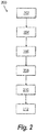
- a method 200 for sensing characteristics of a liquid in a liquid storage vessel includes providing electrical power to an electronics unit, e.g. at least one of electronics units 106, through an antenna, e.g. at least one of antennas 110 or 110', as shown by box 202.
- a remote processing unit e.g. a signal conditioner or remote processing unit 116 or 116', transmits RF energy to the antenna that is operatively connected to the electronics unit located on or within the vessel. It is contemplated that method 200 includes storing power received from the antenna in a battery, e.g. battery 112, in the electronics unit, as indicated by box 204.
- Method 200 includes transmitting power from the electronics unit to the sensor, as indicated schematically by box 206.
- Electronics unit and/or battery are configured to store sufficient RF energy to enable acquisition of the fluid characteristic with the sensor and RF transmission of the information back to the processing unit.
- transmitting power from the electronics unit to the sensor power includes transmitting the power with an optical cable, e.g. optical cable 114.
- Method 200 includes reading at least one of a height sensor, a temperature sensor or a density sensor, e.g. at least one of sensors 102, with the electronics unit, as indicated schematically by box 208.
- reading the sensors includes transmitting data through the optical cable to the electronics unit.
- method 200 includes wirelessly transmitting data from the electronics unit to a remote processing unit, e.g. remote processing unit 116, with the antenna, as indicated schematically by box 210.
- Transmitting and receiving wireless signals to and from the antenna includes transmitting and receiving wireless signals to and from an additional antenna, e.g. antenna 111 or 111', operatively connected to the remote processing unit.
- Method 200 includes sensing a characteristic of liquid in the liquid storage vessel based on the data transmitted to the remote processing unit, as indicated by box 212, for example, determining a liquid level in the liquid storage vessel.
Landscapes
- Physics & Mathematics (AREA)
- Engineering & Computer Science (AREA)
- Fluid Mechanics (AREA)
- General Physics & Mathematics (AREA)
- Power Engineering (AREA)
- Thermal Sciences (AREA)
- Electromagnetism (AREA)
- Signal Processing (AREA)
- Computer Networks & Wireless Communication (AREA)
- Arrangements For Transmission Of Measured Signals (AREA)
Claims (12)
- Sensorsystem (100), umfassend:einen Sensor (102), der wirksam mit einem Flüssigkeitsspeicherbehälter (104) verbunden ist;eine Elektronikeinheit (106), die wirksam mit dem Sensor verbunden ist, wobei die Elektronikeinheit eine Stromquelle beinhaltet, die so konfiguriert ist, dass sie dem Sensor eine elektrische Anregung bereitstellt;eine Antenne (110), die wirksam mit der Elektronikeinheit verbunden ist, um Daten davon zu empfangen und der Stromquelle Energie bereitzustellen, wobei die Antenne drahtlos mit einer Fernverarbeitungseinheit (116) verbunden ist, die sich außerhalb des Flüssigkeitsspeicherbehälters befindet, um Daten an diese zu übermitteln und Energie davon über HF-Signale außerhalb des Flüssigkeitsspeicherbehälters zu empfangen; ein Anregungsmodul (105), das wirksam mit dem Sensor (102) verbunden ist und zwischen dem Sensor (102) und einem optischen Kabel (114) liegt; dadurch gekennzeichnet, dass das optische Kabel (114) innerhalb des Inneren des Flüssigkeitsspeicherbehälters die Elektronikeinheit (106) mit dem Sensor (102) verbindet, um Energie an den Sensor und Daten von dem Sensor zur Elektronikeinheit über das Anregungsmodul (105) zu übertragen; undwobei die Antenne (110) so konfiguriert ist, dass sie mindestens teilweise außerhalb des Flüssigkeitsspeicherbehälters (104) liegt.
- Sensorsystem nach Anspruch 1, wobei der Sensor (102) mindestens teilweise in dem Flüssigkeitsspeicherbehälter angeordnet ist und der Flüssigkeit ausgesetzt ist.
- Sensorsystem nach Anspruch 1 oder 2, wobei der Sensor (102) mindestens eines aus einem induktiven Sensor, einem Widerstandssensor oder einem kapazitiven Sensor ist.
- Sensorsystem nach einem der vorstehenden Ansprüche, wobei der Sensor (102) einer aus einer Vielzahl von Sensoren ist, wobei die Vielzahl von Sensoren mindestens einen aus einem induktiven Sensor, einem Widerstandssensor oder einem kapazitiven Sensor beinhalten.
- Sensorsystem nach einem der vorstehenden Ansprüche, wobei die Fernverarbeitungseinheit (116) wirksam mit einer oder mehreren zusätzlichen Antennen verbunden ist, die so konfiguriert sind, dass sie drahtlose Signal an die Antenne (110) übertragen und von dieser empfangen, die mindestens teilweise außerhalb des Flüssigkeitsspeicherbehälters (104) angeordnet ist.
- Sensorsystem nach einem der vorstehenden Ansprüche, wobei die Stromquelle (108) eine Batterie (112) beinhaltet, die wirksam mit der Antenne (110) verbunden ist, um Energie zu speichern, die von der Antenne empfangen wird.
- Verfahren zum Erfassen von Eigenschaften einer Flüssigkeit, umfassend:Bereitstellen von elektrischer Energie für eine Elektronikeinheit (106) über HF-Signale außerhalb eines Flüssigkeitsspeicherbehälters durch eine Antenne (110), wobei die Elektronikeinheit (106) wirksam mit einem Sensor (102) verbunden ist; Übertragen von Daten von dem Sensor (102) zur Elektronikeinheit (106); unddrahtloses Übertragen der Daten von der Elektronikeinheit (106) an eine Fernverarbeitungseinheit (116) außerhalb des Flüssigkeitsspeicherbehälters mit der Antenne (110), und dadurch gekennzeichnet, dass sie ferner den Schritt des Übertragens elektrischer Anregung mit einem optischen Kabel (114) innerhalb des Inneren des Flüssigkeitsspeicherbehälters von der Elektronikeinheit (106) zum Sensor (102) über ein Anregungsmodul (105) umfasst, wobei das Anregungsmodul (105) wirksam mit dem Sensor (102) verbunden ist und zwischen dem Sensor (102) und dem optischen Kabel (114) liegt; undwobei die Antenne (110) so konfiguriert ist, dass sie mindestens teilweise außerhalb des Flüssigkeitsspeicherbehälters (104) liegt.
- Verfahren nach Anspruch 7, wobei die Daten mindestens eines aus einer Höhe, einer Dichte oder einer Temperatur der Flüssigkeit beinhalten.
- Verfahren nach Anspruch 7 oder 8, ferner umfassend das Ermitteln einer Menge an Flüssigkeit in dem Flüssigkeitsspeicherbehälter (104) basierend auf den Daten, die an die Fernverarbeitungseinheit (116) übermittelt werden.
- Verfahren nach Anspruch 7, 8 oder 9, wobei der Sensor (102) einer aus einer Vielzahl von Sensoren in einem Sensornetzwerk ist, wobei das Sensornetzwerk mindestens eines aus einem Höhensensor, einem Densitometer oder einem Temperatursensor beinhaltet.
- Verfahren nach einem der Ansprüche 7 bis 10, ferner umfassend das Übertragen und Empfangen von drahtlosen Signalen an und von der Antenne (110), wobei mindestens eine zusätzliche Antenne (110) wirksam mit der Fernverarbeitungseinheit (116) verbunden ist.
- Verfahren nach einem der Ansprüche 7 bis 11, ferner umfassend das Speichern von Energie, die von der Antenne empfangen wird, in einer Batterie in der Elektronikeinheit (106).
Applications Claiming Priority (1)
| Application Number | Priority Date | Filing Date | Title |
|---|---|---|---|
| US201662295289P | 2016-02-15 | 2016-02-15 |
Publications (2)
| Publication Number | Publication Date |
|---|---|
| EP3205987A1 EP3205987A1 (de) | 2017-08-16 |
| EP3205987B1 true EP3205987B1 (de) | 2020-12-23 |
Family
ID=58016618
Family Applications (1)
| Application Number | Title | Priority Date | Filing Date |
|---|---|---|---|
| EP17155599.8A Active EP3205987B1 (de) | 2016-02-15 | 2017-02-10 | Sensorsysteme und -verfahren |
Country Status (2)
| Country | Link |
|---|---|
| US (1) | US20170234715A1 (de) |
| EP (1) | EP3205987B1 (de) |
Families Citing this family (1)
| Publication number | Priority date | Publication date | Assignee | Title |
|---|---|---|---|---|
| US11378438B2 (en) | 2018-03-19 | 2022-07-05 | Simmonds Precision Products, Inc. | Fluid measurement interface systems and methods |
Citations (3)
| Publication number | Priority date | Publication date | Assignee | Title |
|---|---|---|---|---|
| US4677305A (en) * | 1985-06-28 | 1987-06-30 | Simmonds Precision Products, Inc. | Opto-acoustic fuel quantity gauging system |
| US20120158321A1 (en) * | 2010-12-16 | 2012-06-21 | Bommer Jason P | Wireless Liquid Quantity Measurement System |
| US20140373622A1 (en) * | 2013-06-21 | 2014-12-25 | Simmonds Precision Products, Inc. | Wireless fuel sensor |
Family Cites Families (7)
| Publication number | Priority date | Publication date | Assignee | Title |
|---|---|---|---|---|
| US4963729A (en) * | 1989-03-03 | 1990-10-16 | Simmonds Precision Products, Inc. | Optically powered sensor system with improved signal conditioning |
| US7263245B2 (en) * | 2005-03-14 | 2007-08-28 | The Boeing Company | Method and apparatus for optically powering and multiplexing distributed fiber optic sensors |
| GB201205074D0 (en) * | 2012-03-22 | 2012-05-09 | Airbus Operations Ltd | Sensor device and method for communicating with sensor devices |
| US9035800B2 (en) * | 2012-10-12 | 2015-05-19 | The Boeing Company | Fuel tank monitoring system |
| US9293033B2 (en) * | 2013-07-16 | 2016-03-22 | The Boeing Company | Wireless fuel sensor system |
| US20150352947A1 (en) * | 2014-06-04 | 2015-12-10 | Purple Services, Inc. | Device and system for automotive refueling |
| RU2678760C2 (ru) * | 2014-08-07 | 2019-01-31 | Зе Боинг Компани | Система беспроводных топливных датчиков |
-
2017
- 2017-02-03 US US15/423,963 patent/US20170234715A1/en not_active Abandoned
- 2017-02-10 EP EP17155599.8A patent/EP3205987B1/de active Active
Patent Citations (3)
| Publication number | Priority date | Publication date | Assignee | Title |
|---|---|---|---|---|
| US4677305A (en) * | 1985-06-28 | 1987-06-30 | Simmonds Precision Products, Inc. | Opto-acoustic fuel quantity gauging system |
| US20120158321A1 (en) * | 2010-12-16 | 2012-06-21 | Bommer Jason P | Wireless Liquid Quantity Measurement System |
| US20140373622A1 (en) * | 2013-06-21 | 2014-12-25 | Simmonds Precision Products, Inc. | Wireless fuel sensor |
Also Published As
| Publication number | Publication date |
|---|---|
| US20170234715A1 (en) | 2017-08-17 |
| EP3205987A1 (de) | 2017-08-16 |
Similar Documents
| Publication | Publication Date | Title |
|---|---|---|
| EP2720006B1 (de) | Kraftstofftanküberwachungssystem | |
| US10362115B2 (en) | Wireless fuel sensor system | |
| US9909916B2 (en) | Wireless fuel sensor system | |
| EP2982943B1 (de) | Wireless-kraftsoffpegelanzeige | |
| EP2816330B1 (de) | Drahtloses Kraftstoffsensorsystem | |
| US11493377B2 (en) | System for sensing flowable substrate levels in a storage unit | |
| EP3205987B1 (de) | Sensorsysteme und -verfahren | |
| EP3462141A1 (de) | Integrales fluidmesssystem | |
| EP3547548B1 (de) | Schnittstellensysteme und -verfahren zur fluidmessung | |
| EP3547547B1 (de) | Fluidcharakterisierungssystem mit integrierter dichtekompensation | |
| BR102017001062A2 (pt) | Sensor system, and, method for sensing characteristics of a liquid. | |
| HUE030705T2 (en) | Measuring instrument, control device and measuring device for charge level measurement |
Legal Events
| Date | Code | Title | Description |
|---|---|---|---|
| PUAI | Public reference made under article 153(3) epc to a published international application that has entered the european phase |
Free format text: ORIGINAL CODE: 0009012 |
|
| STAA | Information on the status of an ep patent application or granted ep patent |
Free format text: STATUS: THE APPLICATION HAS BEEN PUBLISHED |
|
| AK | Designated contracting states |
Kind code of ref document: A1 Designated state(s): AL AT BE BG CH CY CZ DE DK EE ES FI FR GB GR HR HU IE IS IT LI LT LU LV MC MK MT NL NO PL PT RO RS SE SI SK SM TR |
|
| AX | Request for extension of the european patent |
Extension state: BA ME |
|
| STAA | Information on the status of an ep patent application or granted ep patent |
Free format text: STATUS: REQUEST FOR EXAMINATION WAS MADE |
|
| 17P | Request for examination filed |
Effective date: 20180215 |
|
| RBV | Designated contracting states (corrected) |
Designated state(s): AL AT BE BG CH CY CZ DE DK EE ES FI FR GB GR HR HU IE IS IT LI LT LU LV MC MK MT NL NO PL PT RO RS SE SI SK SM TR |
|
| STAA | Information on the status of an ep patent application or granted ep patent |
Free format text: STATUS: EXAMINATION IS IN PROGRESS |
|
| 17Q | First examination report despatched |
Effective date: 20180918 |
|
| RIC1 | Information provided on ipc code assigned before grant |
Ipc: G01F 23/00 20060101ALN20200403BHEP Ipc: G01F 23/26 20060101AFI20200403BHEP Ipc: G01F 22/00 20060101ALN20200403BHEP |
|
| GRAP | Despatch of communication of intention to grant a patent |
Free format text: ORIGINAL CODE: EPIDOSNIGR1 |
|
| STAA | Information on the status of an ep patent application or granted ep patent |
Free format text: STATUS: GRANT OF PATENT IS INTENDED |
|
| RIC1 | Information provided on ipc code assigned before grant |
Ipc: G01F 22/00 20060101ALN20200616BHEP Ipc: G01F 23/26 20060101AFI20200616BHEP Ipc: G01F 23/00 20060101ALN20200616BHEP |
|
| INTG | Intention to grant announced |
Effective date: 20200703 |
|
| GRAS | Grant fee paid |
Free format text: ORIGINAL CODE: EPIDOSNIGR3 |
|
| GRAA | (expected) grant |
Free format text: ORIGINAL CODE: 0009210 |
|
| STAA | Information on the status of an ep patent application or granted ep patent |
Free format text: STATUS: THE PATENT HAS BEEN GRANTED |
|
| AK | Designated contracting states |
Kind code of ref document: B1 Designated state(s): AL AT BE BG CH CY CZ DE DK EE ES FI FR GB GR HR HU IE IS IT LI LT LU LV MC MK MT NL NO PL PT RO RS SE SI SK SM TR |
|
| REG | Reference to a national code |
Ref country code: GB Ref legal event code: FG4D |
|
| REG | Reference to a national code |
Ref country code: DE Ref legal event code: R096 Ref document number: 602017029852 Country of ref document: DE |
|
| REG | Reference to a national code |
Ref country code: AT Ref legal event code: REF Ref document number: 1348181 Country of ref document: AT Kind code of ref document: T Effective date: 20210115 |
|
| REG | Reference to a national code |
Ref country code: IE Ref legal event code: FG4D |
|
| PG25 | Lapsed in a contracting state [announced via postgrant information from national office to epo] |
Ref country code: NO Free format text: LAPSE BECAUSE OF FAILURE TO SUBMIT A TRANSLATION OF THE DESCRIPTION OR TO PAY THE FEE WITHIN THE PRESCRIBED TIME-LIMIT Effective date: 20210323 Ref country code: RS Free format text: LAPSE BECAUSE OF FAILURE TO SUBMIT A TRANSLATION OF THE DESCRIPTION OR TO PAY THE FEE WITHIN THE PRESCRIBED TIME-LIMIT Effective date: 20201223 Ref country code: GR Free format text: LAPSE BECAUSE OF FAILURE TO SUBMIT A TRANSLATION OF THE DESCRIPTION OR TO PAY THE FEE WITHIN THE PRESCRIBED TIME-LIMIT Effective date: 20210324 Ref country code: FI Free format text: LAPSE BECAUSE OF FAILURE TO SUBMIT A TRANSLATION OF THE DESCRIPTION OR TO PAY THE FEE WITHIN THE PRESCRIBED TIME-LIMIT Effective date: 20201223 |
|
| REG | Reference to a national code |
Ref country code: AT Ref legal event code: MK05 Ref document number: 1348181 Country of ref document: AT Kind code of ref document: T Effective date: 20201223 |
|
| REG | Reference to a national code |
Ref country code: NL Ref legal event code: MP Effective date: 20201223 |
|
| PG25 | Lapsed in a contracting state [announced via postgrant information from national office to epo] |
Ref country code: SE Free format text: LAPSE BECAUSE OF FAILURE TO SUBMIT A TRANSLATION OF THE DESCRIPTION OR TO PAY THE FEE WITHIN THE PRESCRIBED TIME-LIMIT Effective date: 20201223 Ref country code: BG Free format text: LAPSE BECAUSE OF FAILURE TO SUBMIT A TRANSLATION OF THE DESCRIPTION OR TO PAY THE FEE WITHIN THE PRESCRIBED TIME-LIMIT Effective date: 20210323 Ref country code: LV Free format text: LAPSE BECAUSE OF FAILURE TO SUBMIT A TRANSLATION OF THE DESCRIPTION OR TO PAY THE FEE WITHIN THE PRESCRIBED TIME-LIMIT Effective date: 20201223 |
|
| PG25 | Lapsed in a contracting state [announced via postgrant information from national office to epo] |
Ref country code: NL Free format text: LAPSE BECAUSE OF FAILURE TO SUBMIT A TRANSLATION OF THE DESCRIPTION OR TO PAY THE FEE WITHIN THE PRESCRIBED TIME-LIMIT Effective date: 20201223 Ref country code: HR Free format text: LAPSE BECAUSE OF FAILURE TO SUBMIT A TRANSLATION OF THE DESCRIPTION OR TO PAY THE FEE WITHIN THE PRESCRIBED TIME-LIMIT Effective date: 20201223 |
|
| REG | Reference to a national code |
Ref country code: LT Ref legal event code: MG9D |
|
| PG25 | Lapsed in a contracting state [announced via postgrant information from national office to epo] |
Ref country code: PT Free format text: LAPSE BECAUSE OF FAILURE TO SUBMIT A TRANSLATION OF THE DESCRIPTION OR TO PAY THE FEE WITHIN THE PRESCRIBED TIME-LIMIT Effective date: 20210423 Ref country code: RO Free format text: LAPSE BECAUSE OF FAILURE TO SUBMIT A TRANSLATION OF THE DESCRIPTION OR TO PAY THE FEE WITHIN THE PRESCRIBED TIME-LIMIT Effective date: 20201223 Ref country code: SK Free format text: LAPSE BECAUSE OF FAILURE TO SUBMIT A TRANSLATION OF THE DESCRIPTION OR TO PAY THE FEE WITHIN THE PRESCRIBED TIME-LIMIT Effective date: 20201223 Ref country code: EE Free format text: LAPSE BECAUSE OF FAILURE TO SUBMIT A TRANSLATION OF THE DESCRIPTION OR TO PAY THE FEE WITHIN THE PRESCRIBED TIME-LIMIT Effective date: 20201223 Ref country code: CZ Free format text: LAPSE BECAUSE OF FAILURE TO SUBMIT A TRANSLATION OF THE DESCRIPTION OR TO PAY THE FEE WITHIN THE PRESCRIBED TIME-LIMIT Effective date: 20201223 Ref country code: SM Free format text: LAPSE BECAUSE OF FAILURE TO SUBMIT A TRANSLATION OF THE DESCRIPTION OR TO PAY THE FEE WITHIN THE PRESCRIBED TIME-LIMIT Effective date: 20201223 Ref country code: LT Free format text: LAPSE BECAUSE OF FAILURE TO SUBMIT A TRANSLATION OF THE DESCRIPTION OR TO PAY THE FEE WITHIN THE PRESCRIBED TIME-LIMIT Effective date: 20201223 |
|
| PG25 | Lapsed in a contracting state [announced via postgrant information from national office to epo] |
Ref country code: AT Free format text: LAPSE BECAUSE OF FAILURE TO SUBMIT A TRANSLATION OF THE DESCRIPTION OR TO PAY THE FEE WITHIN THE PRESCRIBED TIME-LIMIT Effective date: 20201223 Ref country code: PL Free format text: LAPSE BECAUSE OF FAILURE TO SUBMIT A TRANSLATION OF THE DESCRIPTION OR TO PAY THE FEE WITHIN THE PRESCRIBED TIME-LIMIT Effective date: 20201223 |
|
| REG | Reference to a national code |
Ref country code: DE Ref legal event code: R119 Ref document number: 602017029852 Country of ref document: DE |
|
| PG25 | Lapsed in a contracting state [announced via postgrant information from national office to epo] |
Ref country code: MC Free format text: LAPSE BECAUSE OF FAILURE TO SUBMIT A TRANSLATION OF THE DESCRIPTION OR TO PAY THE FEE WITHIN THE PRESCRIBED TIME-LIMIT Effective date: 20201223 Ref country code: IS Free format text: LAPSE BECAUSE OF FAILURE TO SUBMIT A TRANSLATION OF THE DESCRIPTION OR TO PAY THE FEE WITHIN THE PRESCRIBED TIME-LIMIT Effective date: 20210423 |
|
| REG | Reference to a national code |
Ref country code: BE Ref legal event code: MM Effective date: 20210228 |
|
| PG25 | Lapsed in a contracting state [announced via postgrant information from national office to epo] |
Ref country code: LI Free format text: LAPSE BECAUSE OF NON-PAYMENT OF DUE FEES Effective date: 20210228 Ref country code: IT Free format text: LAPSE BECAUSE OF FAILURE TO SUBMIT A TRANSLATION OF THE DESCRIPTION OR TO PAY THE FEE WITHIN THE PRESCRIBED TIME-LIMIT Effective date: 20201223 Ref country code: LU Free format text: LAPSE BECAUSE OF NON-PAYMENT OF DUE FEES Effective date: 20210210 Ref country code: CH Free format text: LAPSE BECAUSE OF NON-PAYMENT OF DUE FEES Effective date: 20210228 Ref country code: AL Free format text: LAPSE BECAUSE OF FAILURE TO SUBMIT A TRANSLATION OF THE DESCRIPTION OR TO PAY THE FEE WITHIN THE PRESCRIBED TIME-LIMIT Effective date: 20201223 |
|
| PLBE | No opposition filed within time limit |
Free format text: ORIGINAL CODE: 0009261 |
|
| STAA | Information on the status of an ep patent application or granted ep patent |
Free format text: STATUS: NO OPPOSITION FILED WITHIN TIME LIMIT |
|
| GBPC | Gb: european patent ceased through non-payment of renewal fee |
Effective date: 20210323 |
|
| PG25 | Lapsed in a contracting state [announced via postgrant information from national office to epo] |
Ref country code: DK Free format text: LAPSE BECAUSE OF FAILURE TO SUBMIT A TRANSLATION OF THE DESCRIPTION OR TO PAY THE FEE WITHIN THE PRESCRIBED TIME-LIMIT Effective date: 20201223 |
|
| 26N | No opposition filed |
Effective date: 20210924 |
|
| PG25 | Lapsed in a contracting state [announced via postgrant information from national office to epo] |
Ref country code: DE Free format text: LAPSE BECAUSE OF NON-PAYMENT OF DUE FEES Effective date: 20210901 Ref country code: ES Free format text: LAPSE BECAUSE OF FAILURE TO SUBMIT A TRANSLATION OF THE DESCRIPTION OR TO PAY THE FEE WITHIN THE PRESCRIBED TIME-LIMIT Effective date: 20201223 Ref country code: GB Free format text: LAPSE BECAUSE OF NON-PAYMENT OF DUE FEES Effective date: 20210323 Ref country code: IE Free format text: LAPSE BECAUSE OF NON-PAYMENT OF DUE FEES Effective date: 20210210 |
|
| PG25 | Lapsed in a contracting state [announced via postgrant information from national office to epo] |
Ref country code: SI Free format text: LAPSE BECAUSE OF FAILURE TO SUBMIT A TRANSLATION OF THE DESCRIPTION OR TO PAY THE FEE WITHIN THE PRESCRIBED TIME-LIMIT Effective date: 20201223 |
|
| PG25 | Lapsed in a contracting state [announced via postgrant information from national office to epo] |
Ref country code: IS Free format text: LAPSE BECAUSE OF FAILURE TO SUBMIT A TRANSLATION OF THE DESCRIPTION OR TO PAY THE FEE WITHIN THE PRESCRIBED TIME-LIMIT Effective date: 20210423 |
|
| PG25 | Lapsed in a contracting state [announced via postgrant information from national office to epo] |
Ref country code: BE Free format text: LAPSE BECAUSE OF NON-PAYMENT OF DUE FEES Effective date: 20210228 |
|
| PGFP | Annual fee paid to national office [announced via postgrant information from national office to epo] |
Ref country code: FR Payment date: 20230119 Year of fee payment: 7 |
|
| PG25 | Lapsed in a contracting state [announced via postgrant information from national office to epo] |
Ref country code: HU Free format text: LAPSE BECAUSE OF FAILURE TO SUBMIT A TRANSLATION OF THE DESCRIPTION OR TO PAY THE FEE WITHIN THE PRESCRIBED TIME-LIMIT; INVALID AB INITIO Effective date: 20170210 |
|
| PG25 | Lapsed in a contracting state [announced via postgrant information from national office to epo] |
Ref country code: CY Free format text: LAPSE BECAUSE OF FAILURE TO SUBMIT A TRANSLATION OF THE DESCRIPTION OR TO PAY THE FEE WITHIN THE PRESCRIBED TIME-LIMIT Effective date: 20201223 |
|
| PG25 | Lapsed in a contracting state [announced via postgrant information from national office to epo] |
Ref country code: MK Free format text: LAPSE BECAUSE OF FAILURE TO SUBMIT A TRANSLATION OF THE DESCRIPTION OR TO PAY THE FEE WITHIN THE PRESCRIBED TIME-LIMIT Effective date: 20201223 |