EP3205928A1 - Kraftfahrzeugscheinwerfer mit einem flüssigkristallmatrixbauteil - Google Patents
Kraftfahrzeugscheinwerfer mit einem flüssigkristallmatrixbauteil Download PDFInfo
- Publication number
- EP3205928A1 EP3205928A1 EP17154621.1A EP17154621A EP3205928A1 EP 3205928 A1 EP3205928 A1 EP 3205928A1 EP 17154621 A EP17154621 A EP 17154621A EP 3205928 A1 EP3205928 A1 EP 3205928A1
- Authority
- EP
- European Patent Office
- Prior art keywords
- light
- optical element
- beam path
- projection lens
- liquid crystal
- Prior art date
- Legal status (The legal status is an assumption and is not a legal conclusion. Google has not performed a legal analysis and makes no representation as to the accuracy of the status listed.)
- Granted
Links
Images



Classifications
-
- F—MECHANICAL ENGINEERING; LIGHTING; HEATING; WEAPONS; BLASTING
- F21—LIGHTING
- F21S—NON-PORTABLE LIGHTING DEVICES; SYSTEMS THEREOF; VEHICLE LIGHTING DEVICES SPECIALLY ADAPTED FOR VEHICLE EXTERIORS
- F21S41/00—Illuminating devices specially adapted for vehicle exteriors, e.g. headlamps
- F21S41/60—Illuminating devices specially adapted for vehicle exteriors, e.g. headlamps characterised by a variable light distribution
- F21S41/68—Illuminating devices specially adapted for vehicle exteriors, e.g. headlamps characterised by a variable light distribution by acting on screens
- F21S41/683—Illuminating devices specially adapted for vehicle exteriors, e.g. headlamps characterised by a variable light distribution by acting on screens by moving screens
- F21S41/689—Flaps, i.e. screens pivoting around one of their edges
-
- F—MECHANICAL ENGINEERING; LIGHTING; HEATING; WEAPONS; BLASTING
- F21—LIGHTING
- F21S—NON-PORTABLE LIGHTING DEVICES; SYSTEMS THEREOF; VEHICLE LIGHTING DEVICES SPECIALLY ADAPTED FOR VEHICLE EXTERIORS
- F21S41/00—Illuminating devices specially adapted for vehicle exteriors, e.g. headlamps
- F21S41/10—Illuminating devices specially adapted for vehicle exteriors, e.g. headlamps characterised by the light source
- F21S41/12—Illuminating devices specially adapted for vehicle exteriors, e.g. headlamps characterised by the light source characterised by the type of emitted light
- F21S41/135—Polarised
-
- F—MECHANICAL ENGINEERING; LIGHTING; HEATING; WEAPONS; BLASTING
- F21—LIGHTING
- F21S—NON-PORTABLE LIGHTING DEVICES; SYSTEMS THEREOF; VEHICLE LIGHTING DEVICES SPECIALLY ADAPTED FOR VEHICLE EXTERIORS
- F21S41/00—Illuminating devices specially adapted for vehicle exteriors, e.g. headlamps
- F21S41/20—Illuminating devices specially adapted for vehicle exteriors, e.g. headlamps characterised by refractors, transparent cover plates, light guides or filters
- F21S41/25—Projection lenses
-
- F—MECHANICAL ENGINEERING; LIGHTING; HEATING; WEAPONS; BLASTING
- F21—LIGHTING
- F21S—NON-PORTABLE LIGHTING DEVICES; SYSTEMS THEREOF; VEHICLE LIGHTING DEVICES SPECIALLY ADAPTED FOR VEHICLE EXTERIORS
- F21S41/00—Illuminating devices specially adapted for vehicle exteriors, e.g. headlamps
- F21S41/30—Illuminating devices specially adapted for vehicle exteriors, e.g. headlamps characterised by reflectors
- F21S41/32—Optical layout thereof
-
- F—MECHANICAL ENGINEERING; LIGHTING; HEATING; WEAPONS; BLASTING
- F21—LIGHTING
- F21S—NON-PORTABLE LIGHTING DEVICES; SYSTEMS THEREOF; VEHICLE LIGHTING DEVICES SPECIALLY ADAPTED FOR VEHICLE EXTERIORS
- F21S41/00—Illuminating devices specially adapted for vehicle exteriors, e.g. headlamps
- F21S41/40—Illuminating devices specially adapted for vehicle exteriors, e.g. headlamps characterised by screens, non-reflecting members, light-shielding members or fixed shades
-
- F—MECHANICAL ENGINEERING; LIGHTING; HEATING; WEAPONS; BLASTING
- F21—LIGHTING
- F21S—NON-PORTABLE LIGHTING DEVICES; SYSTEMS THEREOF; VEHICLE LIGHTING DEVICES SPECIALLY ADAPTED FOR VEHICLE EXTERIORS
- F21S41/00—Illuminating devices specially adapted for vehicle exteriors, e.g. headlamps
- F21S41/60—Illuminating devices specially adapted for vehicle exteriors, e.g. headlamps characterised by a variable light distribution
- F21S41/63—Illuminating devices specially adapted for vehicle exteriors, e.g. headlamps characterised by a variable light distribution by acting on refractors, filters or transparent cover plates
- F21S41/64—Illuminating devices specially adapted for vehicle exteriors, e.g. headlamps characterised by a variable light distribution by acting on refractors, filters or transparent cover plates by changing their light transmissivity, e.g. by liquid crystal or electrochromic devices
- F21S41/645—Illuminating devices specially adapted for vehicle exteriors, e.g. headlamps characterised by a variable light distribution by acting on refractors, filters or transparent cover plates by changing their light transmissivity, e.g. by liquid crystal or electrochromic devices by electro-optic means, e.g. liquid crystal or electrochromic devices
-
- F—MECHANICAL ENGINEERING; LIGHTING; HEATING; WEAPONS; BLASTING
- F21—LIGHTING
- F21S—NON-PORTABLE LIGHTING DEVICES; SYSTEMS THEREOF; VEHICLE LIGHTING DEVICES SPECIALLY ADAPTED FOR VEHICLE EXTERIORS
- F21S41/00—Illuminating devices specially adapted for vehicle exteriors, e.g. headlamps
- F21S41/60—Illuminating devices specially adapted for vehicle exteriors, e.g. headlamps characterised by a variable light distribution
- F21S41/65—Illuminating devices specially adapted for vehicle exteriors, e.g. headlamps characterised by a variable light distribution by acting on light sources
- F21S41/663—Illuminating devices specially adapted for vehicle exteriors, e.g. headlamps characterised by a variable light distribution by acting on light sources by switching light sources
Definitions
- the present invention relates to a motor vehicle headlight according to the preamble of claim 1.
- Such a headlight is from the DE 10 2014 213 636 A1 known. It has a light source, a liquid crystal matrix component, which is arranged in the beam path of light emanating from the light source.
- liquid crystal matrix components are used as a display (LCD) but also in video projectors.
- LCD liquid crystal matrix components
- One Another disadvantage is a rather weak contrast ratio between luminous and non-luminous matrix elements.
- the function of the liquid-crystal matrix elements presupposes, as brightness-controllable segments of a light exit surface of the liquid-crystal matrix component, illumination with linearly polarized light.
- Light of conventional light sources is initially not polarized and has two portions of mutually orthogonal polarization directions.
- the light is polarized before it strikes the liquid crystal matrix device.
- the polarization is usually carried out by a polarizing filter, which passes only one of the two shares almost unchanged and absorbs or reflects the other part.
- This document shows a polarizing beam splitter which splits the unpolarized light of a light source into two parts of different polarization.
- the two components illuminate different regions (matrix elements) of a liquid-crystal matrix component whose transmission can be controlled separately.
- a polarizing beam splitter is arranged between the light source and the liquid crystal matrix component such that it directs the light incident from the light source into a matrix beam path and a light beam
- the base beam path consists of light components of a second polarization direction and without touching the liquid crystal matrix component leads to a first optical element, which bundles the incident light in the base beam path.
- both light components can contribute to the generation of a spotlight distribution.
- the invention allows in this way the efficient generation of a spotlight distribution.
- a rule-conforming basic light distribution or low-beam distribution is generated with the light propagating in the matrix beam path.
- Such a light distribution is characterized in particular by the fact that it does not generate unacceptable glare.
- the headlamp is used as intended during driving, this light is used in particular below the horizon Area of the apron of the motor vehicle illuminated efficiently.
- the second beam path could also be used to produce a low beam distribution or a high beam basic light distribution as shown in FIG DE 10 2008 036 193 occurs.
- a further light distribution supplementing this basic light distribution or low beam distribution to form an overall light distribution can be generated in advance of the vehicle.
- the brightness pattern of the further light distribution can be adjusted with a fineness determined by the number of matrix elements of the liquid crystal matrix.
- the further light distribution is also referred to below as the pixel light distribution. It lies in the apron of the vehicle predominantly above the horizon. A dazzling of other road users who are in the area illuminated by this further light distribution can be avoided or at least reduced by darkening the segment of the liquid matrix component illuminating this road user.
- the headlamp comprises a projection lens, which is arranged and arranged to collect light emanating from the liquid crystal matrix component light of the light source and to direct in the apron of the headlamp.
- a preferred embodiment is characterized in that the first optical element in the base beam path propagating light (low beam) focused in an intermediate image area, which lies in the base beam path between the first optical element and the projection lens, wherein a distance of the intermediate image area of the projection lens of inter-frame focal distance (distance of the focal point from the vertex of the lens surface, which faces the focal point) corresponds to the projection lens.
- the intermediate image area may be a flat or a curved surface.
- an inner light distribution is generated in the intermediate image area as the original image of the basic light distribution or the low-beam distribution, which is projected by the projection lens into the illumination zone in front of the vehicle.
- a further preferred embodiment is characterized by a mirror aperture which has a diaphragm edge and which is arranged in the base beam path (dipped beam) between the first optical element and the projection lens such that the diaphragm edge lies at a distance from the projection lens, which is the inter-frame focal distance of the projection lens corresponds, and which mirror aperture extending from the diaphragm edge in a direction facing from the projection lens to the diaphragm edge direction.
- the diaphragm edge is imaged as a sharp cut-off line.
- the aperture is realized as a mirror aperture with the said arrangement, a high efficiency is achieved, because not shaded for the generation of the dark area of the light distribution shading, but by the reflection contributes to the illumination of the bright area.
- the mirror aperture extends parallel to an optical axis of the projection lens.
- a further preferred embodiment is characterized by a focusing third optical element which is arranged in the matrix beam path (pixel light) between the beam splitter and the intermediate image surface in such a way that it focuses light propagating in the matrix beam path into the intermediate image surface.
- a third optical element is disposed between the light source and the beam splitter and parallelizes the light emanating from the light source before striking the beam splitter.
- a fourth optical element in the base beam path is arranged between the beam splitter and the first optical element such that it focuses light incident from the beam splitter into a focal region of the first optical element, and that light originating from the focal region Light source illuminated the first optical element.
- the light of the light source for illuminating the liquid crystal matrix component is first parallelized by the third optical element, it may be difficult to generate a low beam distribution through an image taken with the first optical element.
- the fourth optical element the light passed through the polarizing beam splitter can be refocused.
- the focal region facing the first optical element can then serve as the light source, from the light of which the first optical element generates a low-beam light distribution.
- a first diaphragm is located between the beam splitter and the first optical element and projects into the base beam path.
- the aperture edge of this aperture is displayed as a cut-off line in the apron.
- This panel can connect in one piece on the side facing away from the edge of the mirror panel. But it is preferably not reflective.
- the diaphragm is located between the fourth optical element and the first optical element and projects into the base beam path. If a projection lens is not present, the diaphragm edge of this diaphragm is imaged by the first optical element as a light-dark boundary in the apron.
- the first diaphragm is movable between a first position, in which it does not protrude into the base beam path, and a second position, in which it projects into the base beam path.
- the basic light or low-beam distribution can be generated both with and without imaging of the diaphragm edge as a sharp cut-off line.
- the polarizer is a thin-film polarizer.
- the polarizer has the basic shape of a beam splitter cube which has a light entry surface facing the light source, a first light exit surface facing the liquid crystal matrix component, a second light exit surface facing the first optical element, and one of the second light exit surfaces Projection lens facing the third light-emitting surface, wherein the light entry surface is curved so that it parallelizes the light incident from the light source, and wherein the second light exit surface is curved so that they are the exiting light in a lying between the second light exit surface and the first optical element Fokal Siemens focused and wherein the third light exit surface is curved so that it focuses light exiting in the intermediate image area.
- a first light exit surface faces the liquid crystal matrix component.
- a further preferred embodiment is characterized in that the cover has a first region which is arranged so that it is preferably illuminated by propagating in the matrix beam light and there has a shape and / or coating in which the reflectance for the first Polarization direction is minimal, and that the cover plate has a second region which is arranged so that it is preferably illuminated by light propagating in the base beam path and which has there a shape and / or coating in which the reflectance for the second polarization direction is minimal.
- the transmission is maximum, which is favorable for a desired high efficiency.
- a depolarizer is arranged, which converts the incident polarized light into unpolarized light, and that in the base beam path (low beam) in the light path after the beam splitter, a depolarizer is arranged, which polarized the incident Light converted to unpolarized light.
- FIG. 1 a first embodiment of a headlamp of a motor vehicle according to the invention.
- the headlight 10 has a housing 12, whose light exit opening is covered by a transparent cover 14.
- a light source 1 Inside the housing 12 there is a light source 1, a first optical element 5, a beam splitter 3, a liquid crystal matrix component 4, optionally a second optical element 6, a third optical element 2, a projection lens 7 and a control unit 8.
- the control unit 20 is adapted, in particular programmed, to control the light source 1 and the properties of the liquid crystal matrix component 4 as a function of signals from a desired driver 18 or a higher-level light control device of the motor vehicle.
- the light source 1 preferably has at least one, but preferably a plurality of light-emitting diodes or laser diodes.
- the third optical element 2 is located in the bundle of light emitted by the light source 1 and is preferably realized as a lens, microlens or catadioptric optical attachment.
- the beam splitter 3 is shown here schematically as a beam splitter cube, which consists of two prismatic halves, which in the plane of the drawing in each case the Have a shape of a right triangle and equilateral triangle and which are along their respective right angle opposite base surfaces are assembled into a cube. Deviating from this schematic representation, which allows a clear representation of the beam paths, the beam splitter is preferably a thin-film polarizer.
- the beam splitter 3 has a light entrance surface 3.1 facing the third optical element 2, a first light entrance and exit surface 3.2 facing the liquid crystal matrix component 4, a second light exit surface 3.3 facing the first optical element 5, and a third light exit surface 3.4 facing the projection lens 7.
- An intermediate image area 9 lies between the optional second optical element 6 and a light entry surface of the projection lens 7.
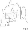
- the FIG. 2 shows different elements from the FIG. 1 together with a matrix beam path 22.
- the third optical element 2 parallelizes outgoing light from the light source 1. This light is not polarized. Via the light entry surface of the beam splitter 3 facing the light source, the parallelized light enters the beam splitter 3 and is split in the interior of the beam splitter 3 into a matrix beam path 22 and a base beam path 24.
- the second beam path 24 is in the FIG. 3 shown.
- the light component propagating in the matrix beam path 22 is linearly polarized in a first direction.
- the propagating in the base beam 24 light component is linearly polarized in a second direction.
- the splitting takes place in the illustrated example in that the first portion at the interface 3.0 of the beam splitter 3 between the two prisms is reflected to the side, while the second portion substantially without changing direction by the Interface 3.0 passes through.
- the light component propagating in the matrix beam path 22 exits the beam splitter 3 via the first light exit surface 3.2 which faces the liquid crystal matrix component 4 and illuminates the liquid crystal matrix component 4 divided into segments (matrix elements).
- the degree of reflection of each segment can be set by the control unit 20. This is possible, for example, with an LCoS component (Liquid Crystal on Silicon).
- a conventional LCoS device causes only the rotation of the polarization in a pixel. The light with the rotated polarization was then no longer reflected at the beam splitter surface 3.0. Unrotated portions are reflected back to the light source 1 at the beam splitter surface 3.0.
- Each individually controllable as a matrix element of the liquid crystal matrix in its optical properties segment thus represents a pixel on the light exit surface of the liquid crystal matrix component 4.
- the resulting in the sum of all pixels on the light exit surface of the liquid crystal matrix component first inner light distribution, if the optional second optical element 6 is present is shown as an intermediate image in the intermediate image area 9.
- the resulting intermediate image since it is still in the housing, also constitutes an internal light distribution.
- This second internal light distribution is projected by the projection lens 7 into a lighting zone in front of the headlight 10.
- a high beam component is generated on a total light distribution of the headlight 10.
- Individual segments of the high-beam component can be controlled in their brightness by controlling the brightness (or the polarization) of the associated matrix element of the liquid-crystal matrix component.
- This proportion of the total light distribution is therefore also referred to as pixel light distribution.
- All embodiments and embodiments may be combined with a depolarizer 13 disposed in one or both beam paths 22, 24 and converting the incident polarized light into unpolarized light.
- the depolarizer 13 may be, for example, a polarization mixer plate or a quarter-wave phase plate.
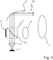
- the FIG. 3 shows elements of the subject FIGS. 1 and 2 with the base beam 24.
- the base beam 24 propagates the light component of the emanating from the light source 1 and entering the beam splitter 3 light, which has passed through the beam splitting interface 3.0 substantially without change of direction. This proportion is also linearly polarized. It has a polarization orthogonal to the polarization of the first component.
- the second component emerges from the beam splitter 3 via the second light exit surface 3.3 of the beam splitter 3, which faces the first optical element 5, and is deflected by the first optical element 5, which is a reflector in this case, so that it passes through the projection lens 7 passes and distributed in advance of the headlight in the form of a basic light distribution or low beam distribution.
- the second beam path 24 is characterized in that, without touching the liquid crystal matrix component 4, it leads to the first optical element 5, which directs the light incident in the base beam path 24 onto the projection lens 7.
- the FIG. 4 shows the base beam path 24 for a second embodiment.
- the second embodiment differs from the first embodiment by the optical properties of the first optical element 5 and in that this embodiment has a mirror aperture 8.
- the first optical element 5 is also a reflector here. Regardless of whether the first optical element 5 is realized as a reflector, lens or catadioptric optics, it is in particular by its shape and arrangement, optionally also by its refractive index, adapted to focus in the base beam 24 propagating light in the intermediate image area 9.
- the intermediate image area 9 lies in the base beam path 24 between the third optical element 5 and the projection lens 7, wherein a distance of the intermediate image area 9 from the projection lens 7 corresponds to the intermediate image-side focal length of the projection lens 7.
- the mirror aperture 8 has a diaphragm edge 8.1 and is arranged in the base beam path 24 between the first optical element 5 and the projection lens 7 such that the diaphragm edge 8.1 is at a distance from the projection lens 7, which corresponds to the inter-frame focal length of the projection lens 7.
- the diaphragm edge 8.1 thus lies in said focal region and is therefore projected as a sharp light-dark boundary in the illumination zone of the headlight 10.
- the mirror aperture 8 extends, starting from the diaphragm edge 8.1, in a direction opposite to the direction in which the projection lens 7 is located. These Direction is preferably parallel to an optical axis of the projection lens 7.
- the reflective effect is preferably achieved by a metallic coating that side 8.2 of the aperture 8, which faces the first optical element 5.
- the projection lens 7 images both the pixel light distribution generated by the matrix beam path 22 and the base light distribution or low beam distribution generated by the basic beam path 24 into the apron of the headlamp 10 so that a total light distribution composed of these two light distributions arises there.
- the FIG. 5 shows a third embodiment.
- the third embodiment differs from the first two embodiments in that a fourth optical element 28 is arranged in the basic beam path 24 (low beam) between the beam splitter 3 and the first optical element 5 so that it is incident from the beam splitter 3 forth light in a focal region of the focused first optical element 5, and that emanating from the focal region light of the light source, the first optical element 5 illuminated.
- the focal region thus represents a kind of light source for polarized light.
- FIG. 5 moreover shows a second diaphragm 30, which is located between the beam splitter 3 and the first optical element 5 and which projects into the basic beam path 24, more precisely into the focal region of the fourth optical element 28.
- a sharp cut-off line is generated in the focal area, which is separated from the first optical element 5 by direct imaging, that is, without being transmitted through the projection lens 7 (shown in FIG. 5 not shown is) to be deflected, is directed into the apron of the headlamp 10.
- the aperture can thus be united with the mirror aperture of the preceding embodiment.
- the second diaphragm 30 is located between the fourth optical element 28 and the first optical element 5 and protrudes into the base beam path 24, as in the FIG. 3 is shown.
- This second beam path consists of largely parallel light.
- the fourth optical element 28 is not present in such a beam path. It may therefore be sufficient to use the second diaphragm 30 without prior focusing by the fourth optical element 28.
- the second diaphragm 30 is movable between a first position, in which it does not project into the base beam path 24, and a second position, in which it projects into the base beam path 24.
- the sharp cut-off line can be replaced by a less sharp light-dark transition, in order to avoid disruptive effects in the overall light distribution, or to produce an alternative high beam distribution. This is the case when not projecting into the beam path aperture.
- the possibility of producing a sharply limited basic light distribution or low-beam distribution remains advantageously preserved.
- the sharp cut-off line is created with the aperture projecting into the beam path.
- the position of the second aperture 30 is also controlled by the controller 20.
- the second diaphragm 30 could also be used in a further embodiment to completely block the base beam path 24.
- FIG. 6 schematically shows a preferred embodiment of the beam splitter as a front optics.
- This beam splitter optical system differs from the beam splitter cube in that its first light entrance surface 3.1, the second light exit surface 3.3 and the third light exit surface 3.4 are convexly curved.
- the second beam path 24 can also be used to generate a different light distribution, for example a sectionfernlichtver gutter or serving for side illumination light distribution.
- the basic light or dipped beam is generated in this embodiment by a separate light module.
- FIG. 7 shows a light distribution 32, as produced by a further embodiment of a headlight according to the invention.
- This light distribution is generated by a designed for installation on the right side of the vehicle headlights.
- the shows FIG. 7 a composite of partial light distributions 34 and 36 total light distribution.
- Horizontal H indicates the position of the horizon when the headlamp is used as intended.
- the vertical V intersects the horizontal H at a point which is defined by the intersection of the main emission of the headlamp or the vehicle longitudinal axis with the horizontal.
- the more central partial light distribution 34 is generated by the first light component propagating in the matrix beam path 22, which can be influenced by the activation of the liquid crystal matrix component 4.
- This more central partial light distribution is supplemented by the laterally partial light distribution 36, which is generated by the second light component propagating in the base beam path 24 by means of a corresponding arrangement and configuration of the first optical element 5.
- a disadvantage of this configuration is that in the driving states in which the lateral light distribution 36 must be switched off, the light source 1 must be switched off, so that then the pixel light distribution 34 is not available in the central part.
- this can be partially compensated by the built-in on the other side of the vehicle headlights or by a switchable aperture 30.
- the turn-on frequency of the side areas 36 is significantly higher than the turn-on frequency of the central area 34, so that the cases where the central area 34 could still be turned on and the side area 36 must be turned off occur less frequently.
- the embodiments described so far use a liquid crystal matrix component adapted for reflection of the incident light.
- the invention can also be realized with liquid-crystal matrix components which are set up to transmit the incident light.
- a polarizing beam splitter 3 as shown in the figure, is to be arranged such that its light exit side 3.2 faces the optical element 6 or the projection lens 7.
- the interface 3.0 of the beam splitter 3 between its two prisms then runs, for example, in the subject of the figure, not as shown there from bottom right to top left, but from bottom left to top right.
Landscapes
- Engineering & Computer Science (AREA)
- General Engineering & Computer Science (AREA)
- Chemical & Material Sciences (AREA)
- Crystallography & Structural Chemistry (AREA)
- Non-Portable Lighting Devices Or Systems Thereof (AREA)
Abstract
Description
- Die vorliegende Erfindung betrifft einen Kraftfahrzeugscheinwerfer nach dem Oberbegriff des Anspruchs 1.
- Ein solcher Scheinwerfer ist aus der
DE 10 2014 213 636 A1 bekannt. Er weist eine Lichtquelle, ein Flüssigkristallmatrixbauteil, das im Strahlengang von Licht angeordnet ist, das von der Lichtquelle ausgeht. - Weitere Scheinwerfer, die Flüssigkristallmatrixbauteile zur Erzeugung von Lichtverteilungen benutzen, sind aus der
DE 10 2013 113 807 A1 oder auchDE 102 013 088 811 A1 bekannt. Flüssigkristallmatrixbauteile werden als Display (LCD), aber auch in Videoprojektoren verwendet. Bei Verwendung in Scheinwerfern bilden die dort herrschenden Umgebungsbedingungen, wie zum Beispiel stark wechselnde Temperaturen, zu überwindende Anwendungshindernisse. Ein weiterer Nachteil besteht in einem eher schwach ausgeprägten Kontrastverhältnis zwischen leuchtenden und nicht leuchtend eingestellten Matrixelementen. - Nachteilig ist auch, dass die Funktion der Flüssigkristallmatrixelemente als in ihrer Helligkeit steuerbare Segmente einer Lichtaustrittsfläche des Flüssigkristallmatrixbauteils eine Beleuchtung mit linear polarisiertem Licht voraussetzt. Licht üblicher Lichtquellen ist zunächst nicht polarisiert und weist zwei Anteile zueinander orthogonaler Polarisationsrichtungen auf. Bei der Verwendung von Flüssigkristallmatrixbauteilen wird das Licht, bevor es auf das Flüssigkristallmatrixbauteil auftrifft, polarisiert. Die Polarisation erfolgt dabei in der Regel durch einen Polarisationsfilter, der nur einen der beiden Anteile nahezu unverändert durchlässt und der den anderen Anteil absorbiert oder reflektiert.
- Aus der
DE 10 2013 113 807 A1 ist es bekannt, beide Anteile zur Erzeugung einer Lichtverteilung zu nutzen. Diese Schrift zeigt einen polarisierenden Strahlteiler, der das unpolarisierte Licht einer Lichtquelle in zwei Anteile unterschiedlicher Polarisation zerlegt. Die beiden Anteile beleuchten unterschiedliche Bereiche (Matrixelemente) eines Flüssigkristallmatrixbauteils, deren Transmission separat steuerbar ist. - Von dem Stand der Technik nach der eingangs genannten
DE 10 2014 213 636 A1 unterscheidet sich die Erfindung durch die kennzeichnenden Merkmale des Anspruchs 1. Demnach ist zwischen der Lichtquelle und dem Flüssigkristallmatrixbauteil ein polarisierender Strahlteiler so angeordnet, dass er das von der Lichtquelle her einfallende Licht in einen Matrixstrahlengang und einen Basisstrahlengang aufteilt, wobei der Matrixstrahlengang aus Lichtanteilen einer ersten Polarisationsrichtung besteht und vom Strahlteiler aus zum Flüssigkristallmatrixbauteil führt und wobei der Basisstrahlengang aus Lichtanteilen einer zweiten Polarisationsrichtung besteht und ohne Berührung des Flüssigkristallmatrixbauteils zu einem ersten optischen Element führt, welches das im Basisstrahlengang einfallende Licht bündelt. - Durch die Aufteilung in zwei Strahlengänge und dadurch, dass Licht beider Polarisationsrichtungen auf die Projektionslinse gerichtet wird, können beide Lichtanteile zur Erzeugung einer Scheinwerferlichtverteilung beitragen.
- Dies verbessert die Effizienz gegenüber der
DE 10 2014 213 636 A1 ganz erheblich. Dadurch, dass der zweite Strahlengang ohne Berührung des Flüssigkristallmatrixbauteils zu einem ersten optischen Element führt, welches das im Basisstrahlengang einfallende Licht bündelt, werden im Basisstrahlengang alle die Lichtverluste vermieden, die auftreten würden, wenn dieser Anteil auch durch das Flüssigkristallmatrixbauteil hindurchtreten müsste oder am Flüssigkristallmatrixbauteil reflektiert werden müsste. - Die Erfindung erlaubt auf diese Weise die effiziente Erzeugung einer Scheinwerferlichtverteilung. Dabei wird mit dem im Matrixstrahlengang propagierenden Licht eine regelkonforme Grundlichtverteilung oder Abblendlichtverteilung erzeugt. Eine solche Lichtverteilung zeichnet sich insbesondere dadurch aus, dass sie keine unzulässige Blendung erzeugt. Bei einer bestimmungsgemäßen Verwendung des Scheinwerfers im Fahrbetrieb wird mit diesem Licht insbesondere ein unterhalb des Horizonts liegender Bereich des Vorfelds des Kraftfahrzeugs effizient ausgeleuchtet. Der zweite Strahlengang könnte auch dazu verwendet werden, eine Abblendlichtverteilung oder eine Fernlichtgrundlichtverteilung zu erzeugen, wie sie in der
DE 10 2008 036 193 vorkommt. - Mit dem im Matrixstrahlengang propagierenden Licht kann eine diese Grundlichtverteilung oder Abblendlichtverteilung zu einer Gesamtlichtverteilung ergänzende weitere Lichtverteilung im Vorfeld des Fahrzeugs erzeugt werden. Dabei ist das Helligkeitsmuster der weiteren Lichtverteilung mit einer durch die Zahl der Matrixelemente der Flüssigkristallmatrix bestimmten Feinheit einstellbar. Die weitere Lichtverteilung wird im Folgenden auch als Pixellichtverteilung bezeichnet. Sie liegt im Vorfeld des Fahrzeugs überwiegend oberhalb des Horizonts. Eine Blendung anderer Verkehrsteilnehmer, die sich im mit dieser weiteren Lichtverteilung ausgeleuchteten Bereich befinden, kann durch Abdunkeln des diesen Verkehrsteilnehmer beleuchtenden Segments des Flüssigkeitsmatrixbauteils vermieden oder zumindest verringert werden.
- Dabei ist bevorzugt, dass der Scheinwerfer eine Projektionslinse aufweist, die dazu eingerichtet und angeordnet ist, von dem Flüssigkristallmatrixbauteil ausgehendes Licht der Lichtquelle zu sammeln und in das Vorfeld des Scheinwerfers zu richten.
- Eine bevorzugte Ausgestaltung zeichnet sich dadurch aus, dass das erste optische Element im Basisstrahlengang propagierendes Licht (Abblendlicht) in eine Zwischenbildfläche fokussiert, die im Basisstrahlengang zwischen dem ersten optischen Element und der Projektionslinse liegt, wobei ein Abstand der Zwischenbildfläche von der Projektionslinse der zwischenbildseitigen Schnittweite (Abstand des Brennpunktes von dem Scheitelpunkt der Linsenfläche, die dem Brennpunkt zugewandt ist) der Projektionslinse entspricht. Die Zwischenbildfläche kann eine ebene oder auch eine gewölbte Fläche sein.
- Durch diese Merkmale wird in der Zwischenbildfläche eine innere Lichtverteilung als Urbild der Grundlichtverteilung oder der Abblendlichtverteilung erzeugt, die durch die Projektionslinse scharf in die vor dem Fahrzeug liegende Beleuchtungszone projiziert wird.
- Eine weitere bevorzugte Ausgestaltung zeichnet sich durch eine Spiegelblende aus, die eine Blendenkante besitzt und die im Basisstrahlengang (Abblendlicht) zwischen dem ersten optischen Element und der Projektionslinse so angeordnet ist, dass die Blendenkante in einem Abstand zur Projektionslinse liegt, welcher der zwischenbildseitigen Schnittweite der Projektionslinse entspricht, und welche Spiegelblende sich von der Blendenkante ausgehend in eine von der Projektionslinse zur Blendenkante weisende Richtung erstreckt.
- Durch diese Merkmale wird die Blendenkante, solange die Lichtaustrittsfläche des Flüssigkristallmatrixbauteils dunkel ist, als scharfe Hell-Dunkel-Grenze abgebildet. Dadurch, dass die Blende als Spiegelblende mit der genannten Anordnung verwirklicht ist, wird eine hohe Effizienz erzielt, weil für die Erzeugung des dunklen Bereichs der Lichtverteilung abzuschattendes Licht nicht verlorengeht, sondern durch die Spiegelung zur Ausleuchtung des hellen Bereichs beiträgt.
- Bevorzugt ist auch, dass sich die Spiegelblende parallel zu einer optischen Achse der Projektionslinse erstreckt.
- Eine weitere bevorzugte Ausgestaltung zeichnet sich durch ein fokussierendes drittes optisches Element aus, das im Matrixstrahlengang (Pixellicht) zwischen dem Strahlteiler und der Zwischenbildfläche so angeordnet ist, dass es im Matrixstrahlengang propagierendes Licht in die Zwischenbildfläche fokussiert.
- Dadurch trägt auch dieses Licht zur Bildung der inneren Lichtverteilung bei, die durch die Projektionslinse in das Vorfeld des Fahrzeugs abgebildet wird. Ein drittes optisches Element ist zwischen der Lichtquelle und dem Strahlteiler angeordnet und parallelisiert das von der Lichtquelle ausgehende Licht, bevor es auf den Strahlteiler trifft.
- Bevorzugt ist auch, dass ein viertes optisches Element im Basisstrahlengang (Abblendlicht) zwischen dem Strahlteiler und dem ersten optischen Element so angeordnet ist, dass es vom Strahlteiler her einfallendes Licht in einen Fokalbereich des ersten optischen Elements fokussiert, und dass von dem Fokalbereich ausgehendes Licht der Lichtquelle das erste optische Element beleuchtet.
- Da das Licht der Lichtquelle zur Beleuchtung des Flüssigkristallmatrixbauteils von dem dritten optischen Element zunächst parallelisiert wird, kann es schwierig sein, eine Abblendlichtverteilung durch eine mit dem ersten optischen Element erfolgende Abbildung zu erzeugen. Mit dem vierten optischen Element kann das durch den polarisierenden Strahlteiler hindurch getretene Licht wieder fokussiert werden. Der dem ersten optischen Element zugewandte Fokalbereich kann dann als Lichtquelle dienen, aus deren Licht das erste optische Element eine Abblendlichtverteilung erzeugt.
- In diesem Zusammenhang ist es vorteilhaft, wenn sich eine erste Blende zwischen dem Strahlteiler und dem ersten optischen Element befindet und in den Basisstrahlengang hineinragt. Die Blendenkante dieser Blende wird als Hell-Dunkel-Grenze in das Vorfeld abgebildet. Diese Blende kann sich einstückig auf der der Kante abgewandten Seite an die Spiegelblende anschließen. Sie ist aber vorzugsweise nicht spiegelnd.
- Bevorzugt ist auch, dass sich die Blende zwischen dem vierten optischen Element und dem ersten optischen Element befindet und in den Basisstrahlengang hineinragt. Die Blendenkante dieser Blende wird dann, wenn eine Projektionslinse nicht vorhanden ist, durch das erste optische Element als Hell-Dunkel-Grenze in das Vorfeld abgebildet.
- Bevorzugt ist auch, dass die erste Blende zwischen einer ersten Stellung, in der sie nicht in den Basisstrahlengang hineinragt, und einer zweiten Stellung, in der sie in den Basisstrahlengang hineinragt, bewegbar ist.
- Dadurch kann die Grundlicht- oder Abblendlichtverteilung sowohl mit als auch ohne Abbildung der Blendenkante als scharfe Hell-Dunkel-Grenze erzeugt werden.
- Bevorzugt ist auch, dass der Polarisator ein Dünnschicht-Polarisator ist.
- Ferner ist bevorzugt, dass der Polarisator die Grundform eines Strahlteilerwürfels besitzt, der eine der Lichtquelle zugewandte Lichteintrittsfläche, eine dem Flüssigkristallmatrixbauteil zugewandte erste Lichtaustrittsfläche, eine dem ersten optischen Element zugewandte zweite Lichtaustrittsfläche und eine der Projektionslinse zugewandte dritte Lichtaustrittsfläche aufweist, wobei die Lichteintrittsfläche so gekrümmt ist, dass sie das von der Lichtquelle her einfallende Licht parallelisiert, und wobei die zweite Lichtaustrittsfläche so gekrümmt ist, das sie das austretende Licht in einen zwischen der zweiten Lichtaustrittsfläche und dem ersten optischen Element liegenden Fokalbereich fokussiert und wobei die dritte Lichtaustrittsfläche so gekrümmt ist, dass sie austretendes Licht in die Zwischenbildfläche fokussiert. Eine erste Lichtaustrittsfläche ist dem Flüssigkristallmatrixbauteil zugewandt.
- Eine weitere bevorzugte Ausgestaltung zeichnet sich dadurch aus, dass die Abdeckscheibe einen ersten Bereich aufweist, der so angeordnet ist, dass er bevorzugt von im Matrixstrahlengang propagierendem Licht beleuchtet wird und der dort eine Form und/oder Beschichtung besitzt, bei welcher der Reflexionsgrad für die erste Polarisationsrichtung minimal wird, und dass die Abdeckscheibe einen zweiten Bereich aufweist, der so angeordnet ist, dass er bevorzugt von im Basisstrahlengang propagierenden Licht beleuchtet wird und der dort eine Form und/oder Beschichtung besitzt, bei welcher der Reflexionsgrad für die zweite Polarisationsrichtung minimal wird. Bei minimaler Reflexion ist die Transmission maximal, was für eine angestrebte hohe Effizienz günstig ist.
- Bevorzugt ist auch, dass in dem Matrixstrahlengang im Lichtweg nach dem Flüssigkristallmatrixbauteil ein Depolarisator angeordnet ist, der das einfallende polarisierte Licht in unpolarisiertes Licht konvertiert, und dass in dem Basisstrahlengang (Abblendlicht) im Lichtweg nach dem Strahlteiler ein Depolarisator angeordnet ist, der das einfallende polarisierte Licht in unpolarisiertes Licht konvertiert. Dadurch können unerwünschte Reflexionseffekte auf spiegelnder Fahrbahn und eine schlechte Sichtbarkeit für Träger von Brillen mit Polarisationsfiltern vermieden werden.
- Weitere Vorteile ergeben sich aus den abhängigen Ansprüchen, der Beschreibung und den beigefügten Figuren.
- Es versteht sich, dass die vorstehend genannten und die nachstehend noch zu erläuternden Merkmale nicht nur in der jeweils angegebenen Kombination, sondern auch in anderen Kombinationen oder in Alleinstellung verwendbar sind, ohne den Rahmen der vorliegenden Erfindung zu verlassen.
- Ausführungsbeispiele der Erfindung sind in den Zeichnungen dargestellt und werden in der nachfolgenden Beschreibung näher erläutert. Dabei bezeichnen gleiche Bezugszeichen in verschiedenen Figuren jeweils gleiche oder zumindest ihrer Funktion nach vergleichbare Elemente. Es zeigen, jeweils in schematischer Form:
- Figur 1
- ein erstes Ausführungsbeispiel eines erfindungsgemäßen Scheinwerfers eines Kraftfahrzeugs;
- Figur 2
- verschiedene Elemente aus der
Figur 1 zusammen mit einem Matrixstrahlengang; - Figur 3
- den Gegenstand der
Figuren 1 und2 mit einem Basisstrahlengang; - Figur 4
- den Basisstrahlengang für ein zweites Ausführungsbeispiel;
- Figur 5
- ein drittes Ausführungsbeispiel;
- Figur 6
- eine bevorzugte Ausgestaltung des Strahlteilers als Vorsatzoptik; und
- Figur 7
- eine Lichtverteilung, wie sie von einem weiteren Ausführungsbeispiel eines erfindungsgemäßen Scheinwerfers erzeugt wird.
- Im Einzelnen zeigt die
Figur 1 ein erstes Ausführungsbeispiel eines erfindungsgemäßen Scheinwerfers eines Kraftfahrzeugs. Der Scheinwerfer 10 weist ein Gehäuse 12 auf, dessen Lichtaustrittsöffnung von einer transparenten Abdeckscheibe 14 abgedeckt wird. - Im Inneren des Gehäuses 12 befindet sich eine Lichtquelle 1, ein erstes optisches Element 5, ein Strahlteiler 3, ein Flüssigkristallmatrixbauteil 4, optional ein zweites optisches Element 6, ein drittes optisches Element 2, eine Projektionslinse 7 und ein Steuergerät 8.
- Das Steuergerät 20 ist dazu eingerichtet, insbesondere dazu programmiert, die Lichtquelle 1 und die Eigenschaften des Flüssigkristallmatrixbauteils 4 in Abhängigkeit von Signalen eines Fahrerwunschgebers 18 oder eines übergeordneten Lichtsteuergeräts des Kraftfahrzeugs zu steuern. Die Lichtquelle 1 weist bevorzugt wenigstens eine, bevorzugt jedoch mehrere Leuchtdioden oder Laserdioden auf.
- Das dritte optische Element 2 befindet sich in dem Bündel des von der Lichtquelle 1 ausgehenden Lichtes und ist bevorzugt als Linse, Mikrolinse oder als katadioptrische Vorsatzoptik verwirklicht.
- Der Strahlteiler 3 ist hier schematisch als Strahlteilerwürfel dargestellt, der aus zwei prismatischen Hälften besteht, die in der Zeichnungsebene jeweils die Form eines rechtwinkligen und gleichseitigen Dreiecks besitzen und die längs ihrer dem jeweiligen rechten Winkel gegenüberliegenden Basisflächen zu einem Würfel zusammengesetzt sind. Abweichend von dieser schematischen Darstellung, die eine übersichtliche Darstellung der Strahlengänge erlaubt, ist der Strahlteiler bevorzugt ein Dünnschichtpolarisator. Der Strahlteiler 3 weist eine dem dritten optischen Element 2 zugewandte Lichteintrittsfläche 3.1, eine dem Flüssigkristallmatrixbauteil 4 zugewandte erste Lichteintritts- und austrittsfläche 3.2, eine dem ersten optischen Element 5 zugewandte zweite Lichtaustrittsfläche 3.3 und eine der Projektionslinse 7 zugewandte dritte Lichtaustrittsfläche 3.4 auf. Eine Zwischenbildfläche 9 liegt zwischen dem optionalen zweiten optischen Element 6 und einer Lichteintrittsfläche der Projektionslinse 7.
- Die
Figur 2 zeigt verschiedene Elemente aus derFigur 1 zusammen mit einem Matrixstrahlengang 22. Das dritte optische Element 2 parallelisiert von der Lichtquelle 1 ausgehendes Licht. Dieses Licht ist nicht polarisiert. Über die der Lichtquelle zugewandte Lichteintrittsfläche des Strahlteilers 3 tritt das parallelisierte Licht in den Strahlteiler 3 ein und wird im Inneren des Strahlteilers 3 in einen Matrixstrahlengang 22 und einen Basisstrahlengang 24 aufgespalten. Der zweite Strahlengang 24 ist in derFigur 3 dargestellt. Der im Matrixstrahlengang 22 propagierende Lichtanteil ist in einer ersten Richtung linear polarisiert. Der im Basisstrahlengang 24 propagierende Lichtanteil ist in einer zweiten Richtung linear polarisiert. Die Aufspaltung geschieht in dem dargestellten Beispiel dadurch, dass der erste Anteil an der Grenzfläche 3.0 des Strahlteilers 3 zwischen den beiden Prismen zur Seite reflektiert wird, während der zweite Anteil im Wesentlichen ohne Richtungsänderung durch die Grenzfläche 3.0 hindurch tritt. Der im Matrixstrahlengang 22 propagierende Lichtanteil tritt über die erste Lichtaustrittsfläche 3.2, die dem Flüssigkristallmatrixbauteil 4 zugewandt ist, aus dem Strahlteiler 3 aus und beleuchtet das in Segmente (Matrixelemente) unterteilte Flüssigkristallmatrixbauteil 4. Der Grad der Reflexion jedes Segmentes ist durch das Steuergerät 20 einstellbar. Dies ist zum Beispiel mit einem LCoS-Bauelement (Liquid Crystal on Silicon) möglich. Ein konventionelles LCoS-Bauteil bewirkt in einem Pixel nur die Drehung der Polarisation. Das Licht mit der gedrehten Polarisation ward dann nicht mehr an der Strahlteilerfläche 3.0 reflektiert. Nicht gedrehte Anteil werden an der Strahlteilerfläche 3.0 wieder zurück in Richtung zur Lichtquelle 1 reflektiert. - Jedes als Matrixelement der Flüssigkristallmatrix in seinen optischen Eigenschaften individuell steuerbare Segment stellt somit einen Pixel auf der Lichtaustrittsfläche des Flüssigkristallmatrixbauteils 4 dar. Die sich in der Summe aller Pixel auf der Lichtaustrittsfläche des Flüssigkristallmatrixbauteils einstellende erste innere Lichtverteilung wird, wenn das optionale zweite optische Element 6 vorhanden ist, als Zwischenbild in die Zwischenbildfläche 9 abgebildet. Das resultierende Zwischenbild stellt, da es sich noch im Gehäuse befindet, ebenfalls noch eine innere Lichtverteilung dar. Diese zweite innere Lichtverteilung wird von der Projektionslinse 7 in eine vor dem Scheinwerfer 10 liegende Beleuchtungszone projiziert. Damit wird in einer bevorzugten Ausgestaltung ein Fernlichtanteil an einer Gesamtlichtverteilung des Scheinwerfers 10 erzeugt. Einzelne Segmente des Fernlichtanteils sind in ihrer Helligkeit durch Steuerung der Helligkeit (bzw. der Polarisation) des zugeordneten Matrixelements des Flüssigkristallmatrixbauteils steuerbar.
- Dieser Anteil an der Gesamtlichtverteilung wird daher auch als Pixellichtverteilung bezeichnet.
- Alle Ausführungsbeispiele und Ausgestaltungen können mit einem Depolarisator 13 kombiniert werden, der in einem oder beiden Strahlengängen 22, 24 angeordnet ist und der das einfallende polarisierte Licht in unpolarisiertes Licht konvertiert. Der Depolarisator 13 kann zum Beispiel eine Polarisationsmischerplatte oder eine Lambda-Viertel-Phasenplatte sein.
- Die
Figur 3 zeigt Elemente des Gegenstands derFiguren 1 und2 mit dem Basisstrahlengang 24. In dem Basisstrahlengang 24 propagiert der Lichtanteil des von der Lichtquelle 1 ausgehenden und in den Strahlteiler 3 eintretenden Lichtes, der im Wesentlichen ohne Richtungsänderung durch die strahlteilende Grenzfläche 3.0 hindurchgetreten ist. Dieser Anteil ist ebenfalls linear polarisiert. Er weist eine zur Polarisation des ersten Anteils orthogonale Polarisation auf. - Der zweite Anteil tritt über die zweite Lichtaustrittsfläche 3.3 des Strahlteilers 3, die dem ersten optischen Element 5 zugewandt ist, aus dem Strahlteiler 3 aus und wird von dem ersten optischen Element 5, das hier ein Reflektor ist, so umgelenkt, dass es durch die Projektionslinse 7 hindurchtritt und sich im Vorfeld des Scheinwerfers in Form einer Grundlichtverteilung oder Abblendlichtverteilung verteilt. Der zweite Strahlengang 24 zeichnet sich dadurch aus, dass er ohne Berührung des Flüssigkristallmatrixbauteils 4 zu dem ersten optischen Element 5 führt, welches das im Basisstrahlengang 24 einfallende Licht auf die Projektionslinse 7 richtet.
- Die
Figur 4 zeigt den Basisstrahlengang 24 für ein zweites Ausführungsbeispiel. Das zweite Ausführungsbeispiel unterscheidet sich von dem ersten Ausführungsbeispiel durch die optischen Eigenschaften des ersten optischen Elements 5 und dadurch, dass dieses Ausführungsbeispiel eine Spiegelblende 8 aufweist. Das erste optische Element 5 ist auch hier ein Reflektor. Unabhängig davon, ob das erste optische Element 5 als Reflektor, Linse oder katadioptrische Optik verwirklicht ist, ist es insbesondere durch seine Form und Anordnung, gegebenenfalls auch noch durch seine Brechzahl, dazu eingerichtet, im Basisstrahlengang 24 propagierendes Licht in die Zwischenbildfläche 9 zu fokussieren. Die Zwischenbildfläche 9 liegt im Basisstrahlengang 24 zwischen dem dritten optischen Element 5 und der Projektionslinse 7, wobei ein Abstand der Zwischenbildfläche 9 von der Projektionslinse 7 der zwischenbildseitigen Schnittweite der Projektionslinse 7 entspricht. Dadurch wird die sich als Folge der Fokussierung in einem Fokalbereich der Projektionslinse 7 einstellende innere Lichtverteilung scharf in die Beleuchtungszone des Scheinwerfers 10 projiziert. - Die Spiegelblende 8 besitzt eine Blendenkante 8.1 und ist im Basisstrahlengang 24 zwischen dem ersten optischen Element 5 und der Projektionslinse 7 so angeordnet, dass die Blendenkante 8.1 in einem Abstand zur Projektionslinse 7 liegt, welcher der zwischenbildseitigen Schnittweite der Projektionslinse 7 entspricht. Die Blendenkante 8.1 liegt damit in dem genannten Fokalbereich und wird daher als scharfe Hell-Dunkel-Grenze in die Beleuchtungszone des Scheinwerfers 10 projiziert.
- Die Spiegelblende 8 erstreckt sich, von der Blendenkante 8.1 ausgehend, in eine Richtung, die zur Richtung, in der die Projektionslinse 7 liegt, entgegengesetzt ist. Diese Richtung ist bevorzugt parallel zu einer optischen Achse der Projektionslinse 7. Die spiegelnde Wirkung wird bevorzugt durch eine metallische Beschichtung derjenigen Seite 8.2 der Blende 8 erzielt, welche dem ersten optischen Element 5 zugewandt ist.
- Die Projektionslinse 7 bildet sowohl die mit dem Matrixstrahlengang 22 erzeugte Pixellichtverteilung als auch die mit dem Basisstrahlengang 24 erzeugte Grundlichtverteilung oder Abblendlichtverteilung in das Vorfeld des Scheinwerfers 10 ab, so dass sich dort insgesamt eine aus diesen beiden Lichtverteilungen zusammengesetzte Gesamtlichtverteilung entsteht.
- Die
Figur 5 zeigt ein drittes Ausführungsbeispiel. Das dritte Ausführungsbeispiel unterscheidet sich von den beiden ersten Ausführungsbeispielen dadurch, dass ein viertes optisches Element 28 im Basisstrahlengang 24 (Abblendlicht) zwischen dem Strahlteiler 3 und dem ersten optischen Element 5 so angeordnet ist, dass es vom Strahlteiler 3 her einfallendes Licht in einen Fokalbereich des ersten optischen Elements 5 fokussiert, und dass von dem Fokalbereich ausgehendes Licht der Lichtquelle das erste optische Element 5 beleuchtet. Der Fokalbereich stellt damit gewissermaßen eine Lichtquelle für polarisiertes Licht dar. -
Figur 5 zeigt darüber hinaus eine zweite Blende 30, die sich zwischen dem Strahlteiler 3 und dem ersten optischen Element 5 befindet und die in den Basisstrahlengang 24, genauer, in den Fokalbereich des vierten optischen Elements 28 hineinragt. Dadurch wird im Fokalbereich eine scharfe Hell-Dunkel-Grenze erzeugt, die von dem ersten optischen Element 5 durch Direktabbildung, also ohne durch die Projektionslinse 7 (die in derFigur 5 nicht dargestellt ist) umgelenkt zu werden, in das Vorfeld des Scheinwerfers 10 gerichtet wird. Die Blende kann so mit der Spiegelblende des vorhergehenden Ausführungsbeispiels vereint sein. - In einer Ausgestaltung befindet sich die zweite Blende 30 zwischen dem vierten optischen Element 28 und dem ersten optischen Element 5 und ragt in den Basisstrahlengang 24 hinein, wie er in der
Figur 3 dargestellt ist. Dieser zweite Strahlengang besteht aus weitgehend parallelem Licht. Im Unterschied zum Gegenstand derFigur 5 ist bei einem solchen Strahlengang das vierte optische Element 28 nicht vorhanden. Es kann also ausreichend sein, die zweite Blende 30 ohne vorherige Fokussierung durch das vierte optische Element 28 zu verwenden. - In einer bevorzugten Ausgestaltung ist die zweite Blende 30 zwischen einer ersten Stellung, in der sie nicht in den Basisstrahlengang 24 hineinragt, und einer zweiten Stellung, in der sie in den Basisstrahlengang 24 hineinragt, bewegbar. Damit kann die scharfe Hell-Dunkel-Grenze beim Bilden einer Gesamtlichtverteilung aus beiden Strahlengängen 22, 24 durch einen weniger scharfen Hell-Dunkel-Übergang ersetzt werden, um störende Effekt in der Gesamtlichtverteilung zu vermeiden, bzw. um eine alternative Fernlichtverteilung zu erzeugen. Dies ist bei nicht in den Strahlengang hineinragender Blende der Fall. Die Möglichkeit, eine scharf begrenzte Grundlichtverteilung oder Abblendlichtverteilung zu erzeugen bleibt dabei vorteilhafterweise erhalten. Die scharfe Hell-Dunkel-Grenze wird bei in den Strahlengang hineinragender Blende erzeugt. Die Stellung der zweiten Blende 30 wird ebenfalls vom Steuergerät 20 gesteuert. Darüber hinaus könnte die zweite Blende 30 in einer weiteren Ausgestaltung auch verwendet werden, um den Basisstrahlengang 24 komplett zu blockieren.
-
Figur 6 zeigt schematisch eine bevorzugte Ausgestaltung des Strahlteilers als Vorsatzoptik. Diese Strahlteilervorsatzoptik unterscheidet sich von dem Strahlteilerwürfel dadurch, dass ihre erste Lichteintrittsfläche 3.1, die zweite Lichtaustrittsfläche 3.3 und die dritte Lichtaustrittsfläche 3.4 konvex gewölbt geformt sind. Dies hat den Vorteil dass das die optischen Elemente 2, 28 und 6 entfallen können. Dadurch wird die gesamte Anordnung kompakter und aufgrund der geringeren Zahl an Teilen kostengünstiger und weniger empfindlich in Bezug auf herstellungsbedingte Toleranzen. - Anstatt der Erzeugung einer Abblendlichtverteilung zu dienen, kann der zweite Strahlengang 24 auch zur Erzeugung einer anderen Lichtverteilung dienen, beispielsweise einer Teilfernlichtverteilung oder einer zur Seitenausleuchtung dienenden Lichtverteilung. Das Grundlicht oder Abblendlicht wird bei dieser Ausgestaltung durch ein separates Lichtmodul erzeugt.
- Das hat den Vorteil, dass die thermische Belastung des Flüssigkristallmatrixbauteils 4, die insbesondere mit der Absorption von Licht verbunden ist, verringert ist, da die Lichtquelle 1 dann, wenn gerade nur Abblendlicht erzeugt werden soll, komplett abgeschaltet werden kann.
-
Figur 7 zeigt eine Lichtverteilung 32, wie sie von einem weiteren Ausführungsbeispiel eines erfindungsgemäßen Scheinwerfers erzeugt wird. Diese Lichtverteilung wird von einem für den Einbau auf der rechten Fahrzeugseite entworfenen Scheinwerfer erzeugt. Im Einzelnen zeigt dieFigur 7 eine aus Teillichtverteilungen 34 und 36 zusammengesetzte Gesamtlichtverteilung. Die Horizontale H gibt die Lage des Horizonts bei einer bestimmungsgemäßen Verwendung des Scheinwerfers an. Die Vertikale V schneidet die Horizontale H in einem Punkt, der durch den Schnittpunkt der Hauptabstrahlrichtung des Scheinwerfers oder der Fahrzeuglängsachse mit der Horizontalen definiert wird. Die zentralere Teillichtverteilung 34 wird von dem im Matrixstrahlengang 22 propagierenden ersten Lichtanteil erzeugt, der durch die Ansteuerung des Flüssigkristallmatrixbauteils 4 beeinflussbar ist. Diese zentralere Teillichtverteilung wird von der seitlicheren Teillichtverteilung 36 ergänzt, die von dem im Basisstrahlengang 24 propagierenden zweiten Lichtanteil durch entsprechende Anordnung und Ausgestaltung des ersten optischen Elements 5 erzeugt wird. - So erhält man im zentraleren Bereich die hoch aufgelöste Pixellichtverteilung 34 und im Seitenbereich eine Lichtverteilung in Form eines Blocksegments 36. Nachteilig an dieser Ausgestaltung ist, dass in den Fahrzuständen, in denen die seitliche Lichtverteilung 36 ausgeschaltet werden muss, die Lichtquelle 1 abgeschaltet werden muss, so dass dann auch die Pixellichtverteilung 34 im zentraleren Teil nicht zur Verfügung steht. Dies kann jedoch teilweise durch den auf der anderen Fahrzeugseite eingebauten Scheinwerfer oder durch eine schaltbare Blende 30 ausgeglichen werden. Außerdem ist die Einschalthäufigkeit der Seitenbereiche 36 signifikant höher als die Einschalthäufigkeit des zentraleren Bereichs 34, so dass die Fälle, in denen der Zentralbereich 34 noch angeschaltet sein könnte und der Seitenbereich 36 ausgeschaltet werden muss, seltener auftreten.
- Die bis hier beschriebenen Ausgestaltungen verwenden ein zur Reflexion des einfallenden Lichtes eingerichtetes Flüssigkristallmatrixbauteil. Die Erfindung ist auch mit Flüssigkristallmatrixbauteilen realisierbar, die zur Transmission des einfallenden Lichtes eingerichtet sind.
- In diesem Fall ist ein polarisierender Strahlteiler 3, wie er in den Figur dargestellt ist, so anzuordnen, dass seine Lichtaustrittsseite 3.2 dem optischen Element 6, beziehungsweise der Projektionslinse 7 zugewandt ist. Die Grenzfläche 3.0 des Strahlteilers 3 zwischen seinen beiden Prismen verläuft dann zum Beispiel beim Gegenstand der Figur nicht wie dort dargestellt von rechts unten nach links oben, sondern von links unten nach rechts oben.
Claims (14)
- Kraftfahrzeugscheinwerfer (10) mit einer Lichtquelle (1) und einem Flüssigkristallmatrixbauteil (4), das im Strahlengang von Licht angeordnet ist, das von der Lichtquelle (1) ausgeht, dadurch gekennzeichnet, dass zwischen der Lichtquelle (1) und dem Flüssigkristallmatrixbauteil (4) ein polarisierender Strahlteiler (3) so angeordnet ist, der das von der Lichtquelle (1) her einfallende Licht in einen Matrixstrahlengang (22) und einen Basisstrahlengang (24) aufteilt, wobei der Matrixstrahlengang vom Strahlteiler (3) aus zum Flüssigkristallmatrixbauteil (4) führt und aus Lichtanteilen besteht, die eine erste Polarisationsrichtung besitzen, und wobei der Basisstrahlengang (24) aus Lichtanteilen besteht, die eine zweite Polarisationsrichtung besitzen, und der ohne Berührung des Flüssigkristallmatrixbauteils (4) zu einem ersten optischen Element (5) führt, welches das im Basisstrahlengang (24) einfallende Licht bündelt.
- Scheinwerfer nach Anspruch 1, gekennzeichnet durch eine Projektionslinse (7), die dazu angeordnet und eingerichtet ist, von dem Flüssigkristallmatrixbauteil (4) ausgehendes Licht der Lichtquelle (1) zu sammeln und in das Vorfeld des Scheinwerfers (10) zu richten.
- Scheinwerfer (10) nach Anspruch 2, dadurch gekennzeichnet, dass das erste optische Element (5) im Basisstrahlengang (24) propagierendes Licht in eine Zwischenbildfläche (9) fokussiert, die im Basisstrahlengang (24) zwischen dem ersten optischen Element (5) und der Projektionslinse (7) liegt, wobei ein Abstand der Zwischenbildfläche (9) von der Projektionslinse (7) der zwischenbildseitigen Schnittweite der Projektionslinse (7) entspricht.
- Scheinwerfer (10) nach einem der Ansprüche 2 oder 3, gekennzeichnet, durch eine Spiegelblende (8), die eine Blendenkante (8.1) besitzt und im Basisstrahlengang (24) zwischen dem ersten optischen Element (5) und der Projektionslinse (7) so angeordnet ist, dass die Blendenkante (8.1) in einem Abstand zur Projektionslinse (7) liegt, welcher der zwischenbildseitigen Schnittweite der Projektionslinse (7) entspricht, und welche Spiegelblende (8) sich von der Blendenkante (8.1) ausgehend in eine von der Projektionslinse (7) zur Blendenkante (8.1) weisende Richtung erstreckt.
- Scheinwerfer (10) nach Anspruch 4, dadurch gekennzeichnet dass sich die Spiegelblende (8) parallel zu einer optischen Achse der Projektionslinse (7) erstreckt.
- Scheinwerfer (10) nach einem der vorhergehenden Ansprüche, gekennzeichnet durch ein zweites optisches Element (6), das im Matrixstrahlengang (22) zwischen dem Strahlteiler (3) und der Zwischenbildfläche (9) so angeordnet ist, dass es im Matrixstrahlengang (22) propagierendes Licht in die Zwischenbildfläche (9) fokussiert.
- Scheinwerfer(10) nach einem der vorhergehenden Ansprüche, dadurch gekennzeichnet, dass ein viertes optisches Element (28) im Basisstrahlengang (24) zwischen dem Strahlteiler (3) und dem ersten optischen Element (5) so angeordnet ist, dass es vom Strahlteiler (3) her einfallendes Licht in einen Fokalbereich des ersten optischen Elements (5) fokussiert, und dass von dem Fokalbereich ausgehendes Licht der Lichtquelle (1) das erste optische Element (5) beleuchtet.
- Scheinwerfer (10) nach einem der vorhergehenden Ansprüche, gekennzeichnet durch eine erste Blende (30), die sich zwischen dem Strahlteiler (3) und dem ersten optischen Element (5) befindet und die in den Basisstrahlengang (24) hineinragt.
- Scheinwerfer (10) nach Anspruch 7, gekennzeichnet durch eine erste Blende (30), die sich zwischen dem vierten optischen Element (28) und dem ersten optischen Element (5) befindet und die in den Basisstrahlengang (24) hineinragt.
- Scheinwerfer (10) nach Anspruch 8 oder 9, dadurch gekennzeichnet, dass die erste Blende (30) zwischen einer ersten Stellung, in der sie nicht in den Basisstrahlengang (24) hineinragt, und einer zweiten Stellung, in der sie in den Basisstrahlengang (24) hineinragt, bewegbar ist.
- Scheinwerfer (10) nach einem der vorhergehenden Ansprüche, dadurch gekennzeichnet, dass der Polarisator (3) ein Dünnschicht-Polarisator ist.
- Scheinwerfer (10) nach Anspruch 12, dadurch gekennzeichnet, dass der Polarisator (3) die Grundform eines Strahlteilerwürfels besitzt, der eine der Lichtquelle (1) zugewandte erste Lichteintrittsfläche (3.1), eine dem ersten optischen Element (5) zugewandte zweite Lichtaustrittsfläche (3.3) und eine der Projektionslinse (7) zugewandte dritte Lichtaustrittsfläche (3.4) aufweist, dadurch gekennzeichnet, dass die Lichteintrittsfläche (3.1) so gekrümmt ist, dass sie das von der Lichtquelle (1) her einfallende Licht parallelisiert, dass die zweite Lichtaustrittsfläche (3.3) so gekrümmt ist, dass sie das austretende Licht in einen zwischen der zweiten Lichtaustrittsfläche (3.3) und dem ersten optischen Element (5) liegenden Fokalbereich des ersten optischen Elements (5) fokussiert und dass die dritte Lichtaustrittsfläche (3.4) so gekrümmt ist, dass sie austretendes Licht in die Zwischenbildfläche (9) fokussiert.
- Scheinwerfer (10) nach einem der vorhergehenden Ansprüche, dadurch gekennzeichnet, dass die Abdeckscheibe (14) einen ersten Bereich aufweist, der so angeordnet ist, dass er bevorzugt von im Matrixstrahlengang (22) propagierenden Licht beleuchtet wird und der dort eine Form besitzt, bei welcher der Reflexionsgrad für die erste Polarisationsrichtung minimal wird, und dass die Abdeckscheibe (14) einen zweiten Bereich (14.2) aufweist, der so angeordnet ist, dass er bevorzugt von im Basisstrahlengang (24) propagierenden Licht beleuchtet wird und der dort eine Form besitzt, bei welcher der Reflexionsgrad für die zweite Polarisationsrichtung minimal wird.
- Scheinwerfer (10) nach einem der vorhergehenden Ansprüche, dadurch gekennzeichnet, dass in dem Matrixstrahlengang (22) im Lichtweg nach dem Flüssigkristallmatrixbauteil (4) ein Depolarisator (13) angeordnet ist, der das einfallende polarisierte Licht in unpolarisiertes Licht konvertiert, und dass in dem Basisstrahlengang (24) im Lichtweg nach dem Strahlteiler (3) ein Depolarisator (13) angeordnet ist, der das einfallende polarisierte Licht in unpolarisiertes Licht konvertiert.
Applications Claiming Priority (1)
| Application Number | Priority Date | Filing Date | Title |
|---|---|---|---|
| DE102016102033.8A DE102016102033A1 (de) | 2016-02-05 | 2016-02-05 | Kraftfahrzeugscheinwerfer mit einem Flüssigkristallmatrixbauteil |
Publications (2)
| Publication Number | Publication Date |
|---|---|
| EP3205928A1 true EP3205928A1 (de) | 2017-08-16 |
| EP3205928B1 EP3205928B1 (de) | 2021-12-29 |
Family
ID=57965785
Family Applications (1)
| Application Number | Title | Priority Date | Filing Date |
|---|---|---|---|
| EP17154621.1A Active EP3205928B1 (de) | 2016-02-05 | 2017-02-03 | Kraftfahrzeugscheinwerfer mit einem flüssigkristallmatrixbauteil |
Country Status (2)
| Country | Link |
|---|---|
| EP (1) | EP3205928B1 (de) |
| DE (1) | DE102016102033A1 (de) |
Cited By (6)
| Publication number | Priority date | Publication date | Assignee | Title |
|---|---|---|---|---|
| CN109827137A (zh) * | 2018-08-16 | 2019-05-31 | 华域视觉科技(上海)有限公司 | 一种激光大灯及其照明系统、激光安全防护方法 |
| EP3547009A1 (de) * | 2018-03-29 | 2019-10-02 | Valeo Vision | Lichtsignalvorrichtung mit lcd-bildschirm |
| EP3572722A1 (de) * | 2018-05-24 | 2019-11-27 | Stanley Electric Co., Ltd. | Fahrzeuglampe, fahrzeuglampensystem |
| WO2020010936A1 (zh) * | 2018-07-13 | 2020-01-16 | 华域视觉科技(上海)有限公司 | 一种基于pbs分光器的自适应远光功能调节方法及其智能车灯模组 |
| WO2021003769A1 (zh) * | 2019-07-11 | 2021-01-14 | 华域视觉科技(上海)有限公司 | 一种基于pbs分光器的前照灯单元 |
| WO2024044424A1 (en) * | 2022-08-25 | 2024-02-29 | Apple Inc. | Vehicle lights with multiple functions |
Families Citing this family (1)
| Publication number | Priority date | Publication date | Assignee | Title |
|---|---|---|---|---|
| JP7044588B2 (ja) * | 2018-03-05 | 2022-03-30 | スタンレー電気株式会社 | 車両用灯具 |
Citations (10)
| Publication number | Priority date | Publication date | Assignee | Title |
|---|---|---|---|---|
| EP0407830A2 (de) * | 1989-07-10 | 1991-01-16 | F. Hoffmann-La Roche Ag | Polarisator |
| DE102008036193A1 (de) | 2008-08-02 | 2010-02-04 | Automotive Lighting Reutlingen Gmbh | Beleuchtungseinrichtung für ein Kraftfahrzeug |
| JP2010176981A (ja) * | 2009-01-28 | 2010-08-12 | Stanley Electric Co Ltd | 車両用灯具 |
| US20120008098A1 (en) * | 2010-07-06 | 2012-01-12 | Seiko Epson Corporation | Light source device and projector |
| JP2012069295A (ja) * | 2010-09-21 | 2012-04-05 | Stanley Electric Co Ltd | 車両用灯具 |
| DE102014213636A1 (de) | 2013-07-16 | 2015-01-22 | Koito Manufacturing Co., Ltd. | Fahrzeugleuchte |
| DE102013108811A1 (de) | 2013-08-14 | 2015-02-19 | Cobra Electronic Gmbh & Co. Kg | Leuchte, insbesondere Scheinwerfer |
| DE102013113807A1 (de) | 2013-12-11 | 2015-06-11 | Hella Kgaa Hueck & Co. | Beleuchtungseinrichtung für ein Kraftfahrzeug |
| DE102015201737A1 (de) * | 2014-02-03 | 2015-08-06 | Koito Manufacturing Co., Ltd. | Fahrzeugleuchte |
| WO2016045879A1 (de) * | 2014-09-23 | 2016-03-31 | Hella Kgaa Hueck & Co. | Scheinwerfer für fahrzeuge |
Family Cites Families (4)
| Publication number | Priority date | Publication date | Assignee | Title |
|---|---|---|---|---|
| DE102008022795B4 (de) * | 2008-05-08 | 2020-01-09 | Osram Opto Semiconductors Gmbh | Kfz-Scheinwerfer |
| JP5287121B2 (ja) * | 2008-10-14 | 2013-09-11 | 株式会社豊田中央研究所 | 車両用照明装置 |
| US8033697B2 (en) * | 2009-02-18 | 2011-10-11 | National Kaohsiung First University Of Science And Technology | Automotive headlight system and adaptive automotive headlight system with instant control and compensation |
| CN105202444A (zh) * | 2014-06-26 | 2015-12-30 | 中强光电股份有限公司 | 车用照明装置 |
-
2016
- 2016-02-05 DE DE102016102033.8A patent/DE102016102033A1/de not_active Withdrawn
-
2017
- 2017-02-03 EP EP17154621.1A patent/EP3205928B1/de active Active
Patent Citations (10)
| Publication number | Priority date | Publication date | Assignee | Title |
|---|---|---|---|---|
| EP0407830A2 (de) * | 1989-07-10 | 1991-01-16 | F. Hoffmann-La Roche Ag | Polarisator |
| DE102008036193A1 (de) | 2008-08-02 | 2010-02-04 | Automotive Lighting Reutlingen Gmbh | Beleuchtungseinrichtung für ein Kraftfahrzeug |
| JP2010176981A (ja) * | 2009-01-28 | 2010-08-12 | Stanley Electric Co Ltd | 車両用灯具 |
| US20120008098A1 (en) * | 2010-07-06 | 2012-01-12 | Seiko Epson Corporation | Light source device and projector |
| JP2012069295A (ja) * | 2010-09-21 | 2012-04-05 | Stanley Electric Co Ltd | 車両用灯具 |
| DE102014213636A1 (de) | 2013-07-16 | 2015-01-22 | Koito Manufacturing Co., Ltd. | Fahrzeugleuchte |
| DE102013108811A1 (de) | 2013-08-14 | 2015-02-19 | Cobra Electronic Gmbh & Co. Kg | Leuchte, insbesondere Scheinwerfer |
| DE102013113807A1 (de) | 2013-12-11 | 2015-06-11 | Hella Kgaa Hueck & Co. | Beleuchtungseinrichtung für ein Kraftfahrzeug |
| DE102015201737A1 (de) * | 2014-02-03 | 2015-08-06 | Koito Manufacturing Co., Ltd. | Fahrzeugleuchte |
| WO2016045879A1 (de) * | 2014-09-23 | 2016-03-31 | Hella Kgaa Hueck & Co. | Scheinwerfer für fahrzeuge |
Cited By (12)
| Publication number | Priority date | Publication date | Assignee | Title |
|---|---|---|---|---|
| EP3547009A1 (de) * | 2018-03-29 | 2019-10-02 | Valeo Vision | Lichtsignalvorrichtung mit lcd-bildschirm |
| FR3079599A1 (fr) * | 2018-03-29 | 2019-10-04 | Valeo Vision | Dispositif de signalisation lumineuse avec ecran lcd |
| CN110332499A (zh) * | 2018-03-29 | 2019-10-15 | 法雷奥照明公司 | 具有液晶显示器的发光信号装置 |
| US10677411B2 (en) | 2018-03-29 | 2020-06-09 | Valeo Vision | Luminous signalling device with LCD |
| EP3572722A1 (de) * | 2018-05-24 | 2019-11-27 | Stanley Electric Co., Ltd. | Fahrzeuglampe, fahrzeuglampensystem |
| CN110529814A (zh) * | 2018-05-24 | 2019-12-03 | 斯坦雷电气株式会社 | 车辆用灯具和车辆用灯具系统 |
| US10551018B2 (en) | 2018-05-24 | 2020-02-04 | Stanley Electric Co., Ltd. | Vehicular lamp, vehicular lamp system |
| WO2020010936A1 (zh) * | 2018-07-13 | 2020-01-16 | 华域视觉科技(上海)有限公司 | 一种基于pbs分光器的自适应远光功能调节方法及其智能车灯模组 |
| CN109827137A (zh) * | 2018-08-16 | 2019-05-31 | 华域视觉科技(上海)有限公司 | 一种激光大灯及其照明系统、激光安全防护方法 |
| WO2021003769A1 (zh) * | 2019-07-11 | 2021-01-14 | 华域视觉科技(上海)有限公司 | 一种基于pbs分光器的前照灯单元 |
| US11746979B2 (en) | 2019-07-11 | 2023-09-05 | HASCO Vision Technology Co., LTD | Headlamp unit based on a polarized beam splitter and at least two light path systems |
| WO2024044424A1 (en) * | 2022-08-25 | 2024-02-29 | Apple Inc. | Vehicle lights with multiple functions |
Also Published As
| Publication number | Publication date |
|---|---|
| EP3205928B1 (de) | 2021-12-29 |
| DE102016102033A1 (de) | 2017-08-10 |
Similar Documents
| Publication | Publication Date | Title |
|---|---|---|
| EP3205928B1 (de) | Kraftfahrzeugscheinwerfer mit einem flüssigkristallmatrixbauteil | |
| EP2799761B1 (de) | Lichtmodul für einen kraftfahrzeugscheinwerfer | |
| DE102009008631B4 (de) | Projektionsmodul für einen Kraftfahrzeugscheinwerfer | |
| EP2934945B1 (de) | Beleuchtungsvorrichtung für ein kraftfahrzeug | |
| DE19930710C2 (de) | Bilddarstellungssystem und -verfahren für Fahrzeuge | |
| DE102014200368B4 (de) | Teilfernlicht-Projektionslichtmodul für einen Kraftfahrzeugscheinwerfer | |
| DE102014215785B4 (de) | Projektionslichtmodul für einen Kraftfahrzeugscheinwerfer | |
| WO2018023141A1 (de) | Kfz scheinwerfer | |
| DE10027018A1 (de) | Scheinwerfer für Fahrzeuge nach dem Projektionsprinzip und Beleuchtungseinrichtung mit wenigstens einem solchen Scheinwerfer | |
| DE202016102988U1 (de) | Scheinwerfer für Kraftfahrzeuge | |
| EP3803197B1 (de) | Kraftfahrzeugscheinwerfer mit mindestens zwei lichtmodulen | |
| EP1792118A1 (de) | Optisches system für einen kraftfahrzeugscheinwerfer, beleuchtungseinheit für einen kraftfahrzeugscheinwerfer und kraftfahrzeugscheinwerfer | |
| WO2016041862A1 (de) | Zur periodischen umlenkung eines laserstrahls eingerichtetes lichtumlenkelement | |
| WO2016045879A1 (de) | Scheinwerfer für fahrzeuge | |
| DE102013205487A1 (de) | Kraftfahrzeugleuchte für dynamische Leuchtenfunktionen | |
| DE102010035767A1 (de) | Projektionsscheinwerfer mit gezielt abgeschwächtem Lichtintensitätsgradienten an der Hell-Dunkel-Grenze | |
| DE102017107781A1 (de) | Primäroptikeinheit für ein Lichtmodul | |
| DE102014115068A1 (de) | Beleuchtungsanordnung | |
| EP3208531B1 (de) | Kraftfahrzeug-scheinwerfer mit einem flüssigkristalldisplay | |
| EP1544660A1 (de) | Anordnung zur Visualisierung von Informationen in einem Kraftfahrzeug | |
| DE102018105720B4 (de) | Lichtmodul für Kraftfahrzeugscheinwerfer | |
| DE102023121275A1 (de) | Leuchtvorrichtung und kraftfahrzeugleuchte | |
| DE102022107687A1 (de) | Lichtmodul eines Kraftfahrzeugscheinwerfers und Verfahren zur Steuerung eines Blendenelements eines solchen Lichtmoduls | |
| AT518713B1 (de) | Vorrichtung und Verfahren zum Projizieren eines Lichtmusters | |
| EP1162401A2 (de) | Scheinwerfer für Fahrzeuge und Beleuchtungseinrichtung mit wenigstens einem solchen Scheinwerfer |
Legal Events
| Date | Code | Title | Description |
|---|---|---|---|
| PUAI | Public reference made under article 153(3) epc to a published international application that has entered the european phase |
Free format text: ORIGINAL CODE: 0009012 |
|
| STAA | Information on the status of an ep patent application or granted ep patent |
Free format text: STATUS: THE APPLICATION HAS BEEN PUBLISHED |
|
| AK | Designated contracting states |
Kind code of ref document: A1 Designated state(s): AL AT BE BG CH CY CZ DE DK EE ES FI FR GB GR HR HU IE IS IT LI LT LU LV MC MK MT NL NO PL PT RO RS SE SI SK SM TR |
|
| AX | Request for extension of the european patent |
Extension state: BA ME |
|
| STAA | Information on the status of an ep patent application or granted ep patent |
Free format text: STATUS: REQUEST FOR EXAMINATION WAS MADE |
|
| 17P | Request for examination filed |
Effective date: 20180215 |
|
| RBV | Designated contracting states (corrected) |
Designated state(s): AL AT BE BG CH CY CZ DE DK EE ES FI FR GB GR HR HU IE IS IT LI LT LU LV MC MK MT NL NO PL PT RO RS SE SI SK SM TR |
|
| STAA | Information on the status of an ep patent application or granted ep patent |
Free format text: STATUS: EXAMINATION IS IN PROGRESS |
|
| 17Q | First examination report despatched |
Effective date: 20180530 |
|
| 17Q | First examination report despatched |
Effective date: 20180612 |
|
| REG | Reference to a national code |
Ref country code: DE Ref legal event code: R079 Ref document number: 502017012322 Country of ref document: DE Free format text: PREVIOUS MAIN CLASS: F21S0008100000 Ipc: F21S0041135000 |
|
| GRAP | Despatch of communication of intention to grant a patent |
Free format text: ORIGINAL CODE: EPIDOSNIGR1 |
|
| STAA | Information on the status of an ep patent application or granted ep patent |
Free format text: STATUS: GRANT OF PATENT IS INTENDED |
|
| RIC1 | Information provided on ipc code assigned before grant |
Ipc: F21S 41/135 20180101AFI20210628BHEP Ipc: F21S 41/25 20180101ALI20210628BHEP Ipc: F21S 41/32 20180101ALI20210628BHEP Ipc: F21S 41/40 20180101ALI20210628BHEP Ipc: F21S 41/64 20180101ALI20210628BHEP Ipc: F21S 41/689 20180101ALI20210628BHEP |
|
| INTG | Intention to grant announced |
Effective date: 20210716 |
|
| GRAS | Grant fee paid |
Free format text: ORIGINAL CODE: EPIDOSNIGR3 |
|
| GRAA | (expected) grant |
Free format text: ORIGINAL CODE: 0009210 |
|
| STAA | Information on the status of an ep patent application or granted ep patent |
Free format text: STATUS: THE PATENT HAS BEEN GRANTED |
|
| AK | Designated contracting states |
Kind code of ref document: B1 Designated state(s): AL AT BE BG CH CY CZ DE DK EE ES FI FR GB GR HR HU IE IS IT LI LT LU LV MC MK MT NL NO PL PT RO RS SE SI SK SM TR |
|
| REG | Reference to a national code |
Ref country code: GB Ref legal event code: FG4D Free format text: NOT ENGLISH |
|
| REG | Reference to a national code |
Ref country code: CH Ref legal event code: EP |
|
| REG | Reference to a national code |
Ref country code: AT Ref legal event code: REF Ref document number: 1458939 Country of ref document: AT Kind code of ref document: T Effective date: 20220115 |
|
| REG | Reference to a national code |
Ref country code: IE Ref legal event code: FG4D Free format text: LANGUAGE OF EP DOCUMENT: GERMAN |
|
| REG | Reference to a national code |
Ref country code: DE Ref legal event code: R096 Ref document number: 502017012322 Country of ref document: DE |
|
| REG | Reference to a national code |
Ref country code: LT Ref legal event code: MG9D |
|
| PG25 | Lapsed in a contracting state [announced via postgrant information from national office to epo] |
Ref country code: RS Free format text: LAPSE BECAUSE OF FAILURE TO SUBMIT A TRANSLATION OF THE DESCRIPTION OR TO PAY THE FEE WITHIN THE PRESCRIBED TIME-LIMIT Effective date: 20211229 Ref country code: LT Free format text: LAPSE BECAUSE OF FAILURE TO SUBMIT A TRANSLATION OF THE DESCRIPTION OR TO PAY THE FEE WITHIN THE PRESCRIBED TIME-LIMIT Effective date: 20211229 Ref country code: FI Free format text: LAPSE BECAUSE OF FAILURE TO SUBMIT A TRANSLATION OF THE DESCRIPTION OR TO PAY THE FEE WITHIN THE PRESCRIBED TIME-LIMIT Effective date: 20211229 Ref country code: BG Free format text: LAPSE BECAUSE OF FAILURE TO SUBMIT A TRANSLATION OF THE DESCRIPTION OR TO PAY THE FEE WITHIN THE PRESCRIBED TIME-LIMIT Effective date: 20220329 |
|
| REG | Reference to a national code |
Ref country code: NL Ref legal event code: MP Effective date: 20211229 |
|
| PG25 | Lapsed in a contracting state [announced via postgrant information from national office to epo] |
Ref country code: SE Free format text: LAPSE BECAUSE OF FAILURE TO SUBMIT A TRANSLATION OF THE DESCRIPTION OR TO PAY THE FEE WITHIN THE PRESCRIBED TIME-LIMIT Effective date: 20211229 Ref country code: NO Free format text: LAPSE BECAUSE OF FAILURE TO SUBMIT A TRANSLATION OF THE DESCRIPTION OR TO PAY THE FEE WITHIN THE PRESCRIBED TIME-LIMIT Effective date: 20220329 Ref country code: LV Free format text: LAPSE BECAUSE OF FAILURE TO SUBMIT A TRANSLATION OF THE DESCRIPTION OR TO PAY THE FEE WITHIN THE PRESCRIBED TIME-LIMIT Effective date: 20211229 Ref country code: HR Free format text: LAPSE BECAUSE OF FAILURE TO SUBMIT A TRANSLATION OF THE DESCRIPTION OR TO PAY THE FEE WITHIN THE PRESCRIBED TIME-LIMIT Effective date: 20211229 Ref country code: GR Free format text: LAPSE BECAUSE OF FAILURE TO SUBMIT A TRANSLATION OF THE DESCRIPTION OR TO PAY THE FEE WITHIN THE PRESCRIBED TIME-LIMIT Effective date: 20220330 |
|
| PG25 | Lapsed in a contracting state [announced via postgrant information from national office to epo] |
Ref country code: NL Free format text: LAPSE BECAUSE OF FAILURE TO SUBMIT A TRANSLATION OF THE DESCRIPTION OR TO PAY THE FEE WITHIN THE PRESCRIBED TIME-LIMIT Effective date: 20211229 |
|
| PG25 | Lapsed in a contracting state [announced via postgrant information from national office to epo] |
Ref country code: SM Free format text: LAPSE BECAUSE OF FAILURE TO SUBMIT A TRANSLATION OF THE DESCRIPTION OR TO PAY THE FEE WITHIN THE PRESCRIBED TIME-LIMIT Effective date: 20211229 Ref country code: SK Free format text: LAPSE BECAUSE OF FAILURE TO SUBMIT A TRANSLATION OF THE DESCRIPTION OR TO PAY THE FEE WITHIN THE PRESCRIBED TIME-LIMIT Effective date: 20211229 Ref country code: RO Free format text: LAPSE BECAUSE OF FAILURE TO SUBMIT A TRANSLATION OF THE DESCRIPTION OR TO PAY THE FEE WITHIN THE PRESCRIBED TIME-LIMIT Effective date: 20211229 Ref country code: PT Free format text: LAPSE BECAUSE OF FAILURE TO SUBMIT A TRANSLATION OF THE DESCRIPTION OR TO PAY THE FEE WITHIN THE PRESCRIBED TIME-LIMIT Effective date: 20220429 Ref country code: ES Free format text: LAPSE BECAUSE OF FAILURE TO SUBMIT A TRANSLATION OF THE DESCRIPTION OR TO PAY THE FEE WITHIN THE PRESCRIBED TIME-LIMIT Effective date: 20211229 Ref country code: EE Free format text: LAPSE BECAUSE OF FAILURE TO SUBMIT A TRANSLATION OF THE DESCRIPTION OR TO PAY THE FEE WITHIN THE PRESCRIBED TIME-LIMIT Effective date: 20211229 Ref country code: CZ Free format text: LAPSE BECAUSE OF FAILURE TO SUBMIT A TRANSLATION OF THE DESCRIPTION OR TO PAY THE FEE WITHIN THE PRESCRIBED TIME-LIMIT Effective date: 20211229 |
|
| PG25 | Lapsed in a contracting state [announced via postgrant information from national office to epo] |
Ref country code: PL Free format text: LAPSE BECAUSE OF FAILURE TO SUBMIT A TRANSLATION OF THE DESCRIPTION OR TO PAY THE FEE WITHIN THE PRESCRIBED TIME-LIMIT Effective date: 20211229 |
|
| PG25 | Lapsed in a contracting state [announced via postgrant information from national office to epo] |
Ref country code: MC Free format text: LAPSE BECAUSE OF FAILURE TO SUBMIT A TRANSLATION OF THE DESCRIPTION OR TO PAY THE FEE WITHIN THE PRESCRIBED TIME-LIMIT Effective date: 20211229 Ref country code: IS Free format text: LAPSE BECAUSE OF FAILURE TO SUBMIT A TRANSLATION OF THE DESCRIPTION OR TO PAY THE FEE WITHIN THE PRESCRIBED TIME-LIMIT Effective date: 20220429 |
|
| REG | Reference to a national code |
Ref country code: DE Ref legal event code: R097 Ref document number: 502017012322 Country of ref document: DE |
|
| REG | Reference to a national code |
Ref country code: CH Ref legal event code: PL |
|
| REG | Reference to a national code |
Ref country code: BE Ref legal event code: MM Effective date: 20220228 |
|
| PG25 | Lapsed in a contracting state [announced via postgrant information from national office to epo] |
Ref country code: LU Free format text: LAPSE BECAUSE OF NON-PAYMENT OF DUE FEES Effective date: 20220203 Ref country code: DK Free format text: LAPSE BECAUSE OF FAILURE TO SUBMIT A TRANSLATION OF THE DESCRIPTION OR TO PAY THE FEE WITHIN THE PRESCRIBED TIME-LIMIT Effective date: 20211229 Ref country code: AL Free format text: LAPSE BECAUSE OF FAILURE TO SUBMIT A TRANSLATION OF THE DESCRIPTION OR TO PAY THE FEE WITHIN THE PRESCRIBED TIME-LIMIT Effective date: 20211229 |
|
| PLBE | No opposition filed within time limit |
Free format text: ORIGINAL CODE: 0009261 |
|
| STAA | Information on the status of an ep patent application or granted ep patent |
Free format text: STATUS: NO OPPOSITION FILED WITHIN TIME LIMIT |
|
| GBPC | Gb: european patent ceased through non-payment of renewal fee |
Effective date: 20220329 |
|
| 26N | No opposition filed |
Effective date: 20220930 |
|
| PG25 | Lapsed in a contracting state [announced via postgrant information from national office to epo] |
Ref country code: FR Free format text: LAPSE BECAUSE OF NON-PAYMENT OF DUE FEES Effective date: 20220228 |
|
| PG25 | Lapsed in a contracting state [announced via postgrant information from national office to epo] |
Ref country code: LI Free format text: LAPSE BECAUSE OF NON-PAYMENT OF DUE FEES Effective date: 20220228 Ref country code: IE Free format text: LAPSE BECAUSE OF NON-PAYMENT OF DUE FEES Effective date: 20220203 Ref country code: GB Free format text: LAPSE BECAUSE OF NON-PAYMENT OF DUE FEES Effective date: 20220329 Ref country code: CH Free format text: LAPSE BECAUSE OF NON-PAYMENT OF DUE FEES Effective date: 20220228 |
|
| PG25 | Lapsed in a contracting state [announced via postgrant information from national office to epo] |
Ref country code: SI Free format text: LAPSE BECAUSE OF FAILURE TO SUBMIT A TRANSLATION OF THE DESCRIPTION OR TO PAY THE FEE WITHIN THE PRESCRIBED TIME-LIMIT Effective date: 20211229 Ref country code: BE Free format text: LAPSE BECAUSE OF NON-PAYMENT OF DUE FEES Effective date: 20220228 |
|
| REG | Reference to a national code |
Ref country code: AT Ref legal event code: MM01 Ref document number: 1458939 Country of ref document: AT Kind code of ref document: T Effective date: 20220203 |
|
| PG25 | Lapsed in a contracting state [announced via postgrant information from national office to epo] |
Ref country code: AT Free format text: LAPSE BECAUSE OF NON-PAYMENT OF DUE FEES Effective date: 20220203 |
|
| PG25 | Lapsed in a contracting state [announced via postgrant information from national office to epo] |
Ref country code: IT Free format text: LAPSE BECAUSE OF FAILURE TO SUBMIT A TRANSLATION OF THE DESCRIPTION OR TO PAY THE FEE WITHIN THE PRESCRIBED TIME-LIMIT Effective date: 20211229 |
|
| PG25 | Lapsed in a contracting state [announced via postgrant information from national office to epo] |
Ref country code: HU Free format text: LAPSE BECAUSE OF FAILURE TO SUBMIT A TRANSLATION OF THE DESCRIPTION OR TO PAY THE FEE WITHIN THE PRESCRIBED TIME-LIMIT; INVALID AB INITIO Effective date: 20170203 |
|
| PG25 | Lapsed in a contracting state [announced via postgrant information from national office to epo] |
Ref country code: MK Free format text: LAPSE BECAUSE OF FAILURE TO SUBMIT A TRANSLATION OF THE DESCRIPTION OR TO PAY THE FEE WITHIN THE PRESCRIBED TIME-LIMIT Effective date: 20211229 Ref country code: CY Free format text: LAPSE BECAUSE OF FAILURE TO SUBMIT A TRANSLATION OF THE DESCRIPTION OR TO PAY THE FEE WITHIN THE PRESCRIBED TIME-LIMIT Effective date: 20211229 |
|
| PG25 | Lapsed in a contracting state [announced via postgrant information from national office to epo] |
Ref country code: MT Free format text: LAPSE BECAUSE OF FAILURE TO SUBMIT A TRANSLATION OF THE DESCRIPTION OR TO PAY THE FEE WITHIN THE PRESCRIBED TIME-LIMIT Effective date: 20211229 |
|
| PG25 | Lapsed in a contracting state [announced via postgrant information from national office to epo] |
Ref country code: TR Free format text: LAPSE BECAUSE OF FAILURE TO SUBMIT A TRANSLATION OF THE DESCRIPTION OR TO PAY THE FEE WITHIN THE PRESCRIBED TIME-LIMIT Effective date: 20211229 |
|
| REG | Reference to a national code |
Ref country code: DE Ref legal event code: R081 Ref document number: 502017012322 Country of ref document: DE Owner name: MARELLI GERMANY GMBH, DE Free format text: FORMER OWNER: AUTOMOTIVE LIGHTING REUTLINGEN GMBH, 72762 REUTLINGEN, DE |
|
| PGFP | Annual fee paid to national office [announced via postgrant information from national office to epo] |
Ref country code: DE Payment date: 20260121 Year of fee payment: 10 |