EP3205863A1 - System and method for estimating turbo speed of an engine - Google Patents
System and method for estimating turbo speed of an engine Download PDFInfo
- Publication number
- EP3205863A1 EP3205863A1 EP17152074.5A EP17152074A EP3205863A1 EP 3205863 A1 EP3205863 A1 EP 3205863A1 EP 17152074 A EP17152074 A EP 17152074A EP 3205863 A1 EP3205863 A1 EP 3205863A1
- Authority
- EP
- European Patent Office
- Prior art keywords
- air
- compressor
- measure
- throttle
- pressure
- Prior art date
- Legal status (The legal status is an assumption and is not a legal conclusion. Google has not performed a legal analysis and makes no representation as to the accuracy of the status listed.)
- Granted
Links
Images



Classifications
-
- F—MECHANICAL ENGINEERING; LIGHTING; HEATING; WEAPONS; BLASTING
- F02—COMBUSTION ENGINES; HOT-GAS OR COMBUSTION-PRODUCT ENGINE PLANTS
- F02D—CONTROLLING COMBUSTION ENGINES
- F02D41/00—Electrical control of supply of combustible mixture or its constituents
- F02D41/02—Circuit arrangements for generating control signals
- F02D41/14—Introducing closed-loop corrections
- F02D41/1401—Introducing closed-loop corrections characterised by the control or regulation method
-
- F—MECHANICAL ENGINEERING; LIGHTING; HEATING; WEAPONS; BLASTING
- F02—COMBUSTION ENGINES; HOT-GAS OR COMBUSTION-PRODUCT ENGINE PLANTS
- F02D—CONTROLLING COMBUSTION ENGINES
- F02D41/00—Electrical control of supply of combustible mixture or its constituents
- F02D41/02—Circuit arrangements for generating control signals
- F02D41/14—Introducing closed-loop corrections
-
- F—MECHANICAL ENGINEERING; LIGHTING; HEATING; WEAPONS; BLASTING
- F02—COMBUSTION ENGINES; HOT-GAS OR COMBUSTION-PRODUCT ENGINE PLANTS
- F02B—INTERNAL-COMBUSTION PISTON ENGINES; COMBUSTION ENGINES IN GENERAL
- F02B37/00—Engines characterised by provision of pumps driven at least for part of the time by exhaust
- F02B37/12—Control of the pumps
-
- F—MECHANICAL ENGINEERING; LIGHTING; HEATING; WEAPONS; BLASTING
- F02—COMBUSTION ENGINES; HOT-GAS OR COMBUSTION-PRODUCT ENGINE PLANTS
- F02D—CONTROLLING COMBUSTION ENGINES
- F02D41/00—Electrical control of supply of combustible mixture or its constituents
-
- F—MECHANICAL ENGINEERING; LIGHTING; HEATING; WEAPONS; BLASTING
- F02—COMBUSTION ENGINES; HOT-GAS OR COMBUSTION-PRODUCT ENGINE PLANTS
- F02D—CONTROLLING COMBUSTION ENGINES
- F02D41/00—Electrical control of supply of combustible mixture or its constituents
- F02D41/0002—Controlling intake air
- F02D41/0007—Controlling intake air for control of turbo-charged or super-charged engines
-
- F—MECHANICAL ENGINEERING; LIGHTING; HEATING; WEAPONS; BLASTING
- F02—COMBUSTION ENGINES; HOT-GAS OR COMBUSTION-PRODUCT ENGINE PLANTS
- F02D—CONTROLLING COMBUSTION ENGINES
- F02D41/00—Electrical control of supply of combustible mixture or its constituents
- F02D41/24—Electrical control of supply of combustible mixture or its constituents characterised by the use of digital means
- F02D41/26—Electrical control of supply of combustible mixture or its constituents characterised by the use of digital means using computer, e.g. microprocessor
- F02D41/263—Electrical control of supply of combustible mixture or its constituents characterised by the use of digital means using computer, e.g. microprocessor the program execution being modifiable by physical parameters
-
- F—MECHANICAL ENGINEERING; LIGHTING; HEATING; WEAPONS; BLASTING
- F02—COMBUSTION ENGINES; HOT-GAS OR COMBUSTION-PRODUCT ENGINE PLANTS
- F02D—CONTROLLING COMBUSTION ENGINES
- F02D9/00—Controlling engines by throttling air or fuel-and-air induction conduits or exhaust conduits
- F02D9/02—Controlling engines by throttling air or fuel-and-air induction conduits or exhaust conduits concerning induction conduits
-
- F—MECHANICAL ENGINEERING; LIGHTING; HEATING; WEAPONS; BLASTING
- F02—COMBUSTION ENGINES; HOT-GAS OR COMBUSTION-PRODUCT ENGINE PLANTS
- F02D—CONTROLLING COMBUSTION ENGINES
- F02D9/00—Controlling engines by throttling air or fuel-and-air induction conduits or exhaust conduits
- F02D9/08—Throttle valves specially adapted therefor; Arrangements of such valves in conduits
- F02D9/10—Throttle valves specially adapted therefor; Arrangements of such valves in conduits having pivotally-mounted flaps
- F02D9/1035—Details of the valve housing
- F02D9/105—Details of the valve housing having a throttle position sensor
-
- F—MECHANICAL ENGINEERING; LIGHTING; HEATING; WEAPONS; BLASTING
- F02—COMBUSTION ENGINES; HOT-GAS OR COMBUSTION-PRODUCT ENGINE PLANTS
- F02M—SUPPLYING COMBUSTION ENGINES IN GENERAL WITH COMBUSTIBLE MIXTURES OR CONSTITUENTS THEREOF
- F02M35/00—Combustion-air cleaners, air intakes, intake silencers, or induction systems specially adapted for, or arranged on, internal-combustion engines
- F02M35/10—Air intakes; Induction systems
- F02M35/10373—Sensors for intake systems
- F02M35/1038—Sensors for intake systems for temperature or pressure
-
- F—MECHANICAL ENGINEERING; LIGHTING; HEATING; WEAPONS; BLASTING
- F02—COMBUSTION ENGINES; HOT-GAS OR COMBUSTION-PRODUCT ENGINE PLANTS
- F02M—SUPPLYING COMBUSTION ENGINES IN GENERAL WITH COMBUSTIBLE MIXTURES OR CONSTITUENTS THEREOF
- F02M35/00—Combustion-air cleaners, air intakes, intake silencers, or induction systems specially adapted for, or arranged on, internal-combustion engines
- F02M35/10—Air intakes; Induction systems
- F02M35/10373—Sensors for intake systems
- F02M35/10386—Sensors for intake systems for flow rate
-
- F—MECHANICAL ENGINEERING; LIGHTING; HEATING; WEAPONS; BLASTING
- F02—COMBUSTION ENGINES; HOT-GAS OR COMBUSTION-PRODUCT ENGINE PLANTS
- F02M—SUPPLYING COMBUSTION ENGINES IN GENERAL WITH COMBUSTIBLE MIXTURES OR CONSTITUENTS THEREOF
- F02M35/00—Combustion-air cleaners, air intakes, intake silencers, or induction systems specially adapted for, or arranged on, internal-combustion engines
- F02M35/10—Air intakes; Induction systems
- F02M35/104—Intake manifolds
-
- G—PHYSICS
- G01—MEASURING; TESTING
- G01M—TESTING STATIC OR DYNAMIC BALANCE OF MACHINES OR STRUCTURES; TESTING OF STRUCTURES OR APPARATUS, NOT OTHERWISE PROVIDED FOR
- G01M15/00—Testing of engines
- G01M15/14—Testing gas-turbine engines or jet-propulsion engines
-
- F—MECHANICAL ENGINEERING; LIGHTING; HEATING; WEAPONS; BLASTING
- F02—COMBUSTION ENGINES; HOT-GAS OR COMBUSTION-PRODUCT ENGINE PLANTS
- F02B—INTERNAL-COMBUSTION PISTON ENGINES; COMBUSTION ENGINES IN GENERAL
- F02B37/00—Engines characterised by provision of pumps driven at least for part of the time by exhaust
- F02B37/12—Control of the pumps
- F02B2037/122—Control of rotational speed of the pump
-
- F—MECHANICAL ENGINEERING; LIGHTING; HEATING; WEAPONS; BLASTING
- F02—COMBUSTION ENGINES; HOT-GAS OR COMBUSTION-PRODUCT ENGINE PLANTS
- F02D—CONTROLLING COMBUSTION ENGINES
- F02D41/00—Electrical control of supply of combustible mixture or its constituents
- F02D41/02—Circuit arrangements for generating control signals
- F02D41/14—Introducing closed-loop corrections
- F02D41/1401—Introducing closed-loop corrections characterised by the control or regulation method
- F02D2041/1413—Controller structures or design
- F02D2041/1415—Controller structures or design using a state feedback or a state space representation
- F02D2041/1416—Observer
-
- F—MECHANICAL ENGINEERING; LIGHTING; HEATING; WEAPONS; BLASTING
- F02—COMBUSTION ENGINES; HOT-GAS OR COMBUSTION-PRODUCT ENGINE PLANTS
- F02D—CONTROLLING COMBUSTION ENGINES
- F02D41/00—Electrical control of supply of combustible mixture or its constituents
- F02D41/02—Circuit arrangements for generating control signals
- F02D41/14—Introducing closed-loop corrections
- F02D41/1401—Introducing closed-loop corrections characterised by the control or regulation method
- F02D2041/1433—Introducing closed-loop corrections characterised by the control or regulation method using a model or simulation of the system
-
- F—MECHANICAL ENGINEERING; LIGHTING; HEATING; WEAPONS; BLASTING
- F02—COMBUSTION ENGINES; HOT-GAS OR COMBUSTION-PRODUCT ENGINE PLANTS
- F02D—CONTROLLING COMBUSTION ENGINES
- F02D2200/00—Input parameters for engine control
- F02D2200/02—Input parameters for engine control the parameters being related to the engine
- F02D2200/04—Engine intake system parameters
- F02D2200/0402—Engine intake system parameters the parameter being determined by using a model of the engine intake or its components
-
- F—MECHANICAL ENGINEERING; LIGHTING; HEATING; WEAPONS; BLASTING
- F02—COMBUSTION ENGINES; HOT-GAS OR COMBUSTION-PRODUCT ENGINE PLANTS
- F02D—CONTROLLING COMBUSTION ENGINES
- F02D2200/00—Input parameters for engine control
- F02D2200/02—Input parameters for engine control the parameters being related to the engine
- F02D2200/04—Engine intake system parameters
- F02D2200/0404—Throttle position
-
- F—MECHANICAL ENGINEERING; LIGHTING; HEATING; WEAPONS; BLASTING
- F02—COMBUSTION ENGINES; HOT-GAS OR COMBUSTION-PRODUCT ENGINE PLANTS
- F02D—CONTROLLING COMBUSTION ENGINES
- F02D2200/00—Input parameters for engine control
- F02D2200/02—Input parameters for engine control the parameters being related to the engine
- F02D2200/04—Engine intake system parameters
- F02D2200/0406—Intake manifold pressure
-
- F—MECHANICAL ENGINEERING; LIGHTING; HEATING; WEAPONS; BLASTING
- F02—COMBUSTION ENGINES; HOT-GAS OR COMBUSTION-PRODUCT ENGINE PLANTS
- F02D—CONTROLLING COMBUSTION ENGINES
- F02D2200/00—Input parameters for engine control
- F02D2200/02—Input parameters for engine control the parameters being related to the engine
- F02D2200/04—Engine intake system parameters
- F02D2200/0414—Air temperature
-
- Y—GENERAL TAGGING OF NEW TECHNOLOGICAL DEVELOPMENTS; GENERAL TAGGING OF CROSS-SECTIONAL TECHNOLOGIES SPANNING OVER SEVERAL SECTIONS OF THE IPC; TECHNICAL SUBJECTS COVERED BY FORMER USPC CROSS-REFERENCE ART COLLECTIONS [XRACs] AND DIGESTS
- Y02—TECHNOLOGIES OR APPLICATIONS FOR MITIGATION OR ADAPTATION AGAINST CLIMATE CHANGE
- Y02T—CLIMATE CHANGE MITIGATION TECHNOLOGIES RELATED TO TRANSPORTATION
- Y02T10/00—Road transport of goods or passengers
- Y02T10/10—Internal combustion engine [ICE] based vehicles
- Y02T10/12—Improving ICE efficiencies
Definitions
- the present disclosure pertains generally to automotive engine controls, and more particularly pertains to estimating the rotation speed of a turbocharger of the engine.
- the speed at which a turbocharger rotates is an important parameter in controlling operation of turbocharged engines.
- the maximum turbo speed may define a maximum achievable air flow, which in turn defines a maximum achievable torque of the engine. Exceeding the maximum turbo speed can lead to mechanical damage to the turbocharger and can ultimately lead to engine failure.
- a goal in controlling operation of some turbocharged engines, therefore, is the ability to achieve a high turbo speed without exceeding the maximum allowed speed.
- the turbo speed may be directly measured by a dedicated speed sensor that may, for example, utilize blade counting or the like. This tends to be an expensive solution.
- a less expensive alternative is to estimate the turbo speed using inputs from other sensors utilized in engine management.
- the turbo speed may be estimated using mass air flow, compressor inlet pressure, compressor outlet pressure and compressor inlet temperature. In some cases, these values may be related via a compressor map in which the turbo speed may simply be looked up once the other values are measured and known.
- a shortcoming of this estimation method is that a compressor outlet pressure sensor must be placed at the output of the turbo's compressor. Most contemporary engine designs do not include a compressor outlet pressure sensor. Thus, the addition of the compressor outlet pressure sensor may increase the cost of the engine management system, and may even reduce the reliability of the system since there is an additional failure mechanism.
- Modern vehicles often include a Manifold Absolute Pressure (MAP) sensor for sensing the pressure at the intake manifold of the engine.
- the MAP sensor is often used to control the operation of the engine.
- the MAP sensor is typically located at the intake manifold of the engine, and for engines with a turbocharger, the MAP sensor is typically located downstream of the turbocharger's compressor outlet, and in most cases downstream of the engine's throttle valve.
- a charge air cooler is disposed between the compressor outlet and the throttle valve. The charge air cooler, when provided, may cool the compressed air provided by the compressor in order to provide a more dense intake charge into the engine, which can increase the power output of the engine.
- the present disclosure relates to techniques for estimating the turbo speed of a turbocharger using data from a pressure sensor that is located downstream of the throttle valve, such as the MAP sensor, instead of a compressor outlet pressure sensor that is located at the output of the compressor. This approach may reduce the cost and increase the reliability of the engine management system.
- a controller may be used to estimate an operating speed of a turbocharger that has a compressor with an air inlet and an air outlet.
- the compressor feeds compressed air to a downstream throttle that provides a throttled air flow to an air intake manifold of an engine.
- the controller may include an inlet port, an outlet port and a processor that is operatively coupled to the inlet port and the outlet port.
- the inlet port may receive one or more of a compressor air flow signal that represents a measure of air flow through the compressor, a compressor air inlet pressure signal that represents a measure of pressure at the air inlet of the compressor, an intake manifold pressure signal that represents a measure of pressure at the air intake manifold of the engine, a temperature signal that represents the temperature of the air at the throttle, and a throttle signal that represents the throttle position of the throttle.
- the controller may include a memory that stores instructions that are executable by the processor to estimate the operating speed of the turbocharger based at least in part on the values received by the inlet port.
- the processor may provide one or more control signals via the output port to control an operation of the turbocharger and/or the engine in response to the estimated operating speed of the turbocharger.
- a controller may be used to estimate an operating speed of a turbocharger that has a compressor with an air inlet and an air outlet.
- the compressor feeds compressed air to a downstream throttle that provides a throttled air flow to an air intake manifold of an engine.
- the controller may include an inlet port, an outlet port and a processor that is operatively coupled to the inlet port and the outlet port.
- the inlet port may receive one or more of a compressor air flow signal that represents a measure of air flow through the compressor, a compressor air inlet pressure signal that represents a measure of pressure at the air inlet of the compressor, an intake manifold pressure signal that represents a measure of pressure at the air intake manifold of the engine and a throttle signal that represents the throttle position of the throttle.
- the controller may include a memory that stores instructions that are executable by the processor to estimate an air pressure at the air outlet of the compressor using a throttle model that references at least the throttle signal and the measure of pressure at the air intake manifold of the engine.
- the controller may further estimate the operating speed of the turbocharger using a turbocharger model that references at least the measure of air flow through the compressor, the measure of pressure at the air inlet of the compressor and the estimated air pressure at the air outlet of the compressor.
- the processor may provide one or more control signals via the output port to control an operation of the turbocharger and/or the engine in response to the estimated operating speed of the turbocharger.
- references in the specification to "an embodiment”, “some embodiments”, “other embodiments”, etc. indicate that the embodiment described may include one or more particular features, structures, and/or characteristics. However, such recitations do not necessarily mean that all embodiments include the particular features, structures, and/or characteristics. Additionally, when particular features, structures, and/or characteristics are described in connection with one embodiment, it should be understood that such features, structures, and/or characteristics may also be used connection with other embodiments whether or not explicitly described unless clearly stated to the contrary.
- Figure 1 is a schematic illustration of an air inlet system 10 that may, for example, be used in combination with any suitable gasoline and/or diesel-powered engine. It will be appreciated that in some cases the air inlet system 10 may include additional components not shown in Figure 1 . As illustrated, the air inlet system 10 may include a throttle valve 12 that is positioned upstream of an air intake manifold 14. The throttle valve has an air inlet 11 and an air outlet 13.
- Air entering the air intake manifold 14 can be mixed with fuel and fed into the combustion chambers via one or more intake valves disposed atop each engine cylinder.
- fuel may be directly injected into each engine cylinder. In these engines, fuel is not mixed with air within the air intake manifold 14 itself.
- the throttle valve 12 may be opened further, to provide additional air, or at least partially closed, to provide less air, in response to a throttle command signal emanating from an engine management system (not shown).
- the engine management system may provide a command signal to change the position of the throttle valve 12 in response to the driver pushing harder on the accelerator pedal, or perhaps taking their foot off the accelerator pedal.
- the engine management system may provide a throttle command signal to change the position of the throttle valve 12 in order to maintain a desired speed in response to a cruise control system (not shown). While the engine management system is generally referenced herein as a unitary control structure, it will be appreciated that in actuality, the engine management system may include a number of distinct computers, controllers, processors, sensors and the like.
- air entering the air inlet system 10 is provided to a compressor 16 of a turbocharger.
- the compressor 16 includes an air inlet 15 and an air outlet 17. It will be appreciated that compressor 16 is disposed within the air intake flow.
- the turbocharger will typically also include a drive turbine (not shown) that is disposed within an exhaust gas flow of the engine. Gases within the exhaust flow cause the drive turbine to rotate.
- the drive turbine typically drives the compressor 16 via a compressor drive shaft.
- the compressor 16, which is disposed within the air intake flow rotates via the aforementioned shaft. As the compressor 16 rotates, it draws air through the air inlet 15, compresses the air, and provides the compressed air to the air outlet 17.
- Air entering the compressor 16 at the air inlet 15 is generally at or close to ambient pressure, while air exiting the compressor 16 at the air outlet 17 is at an increased pressure relative to ambient pressure.
- the air passing through the compressor 16 may be heated as a result of being compressed, as well through some engine heating.
- a charge air cooler 18 may be disposed downstream of the compressor 16 in order to cool the air before it reaches the throttle valve 12 and the air intake manifold 14 of the engine.
- the charge air cooler 18, when provided, may cool the compressed air provided by the compressor 16 in order to provide a more dense intake charge into the engine, which can increase the power output of the engine.
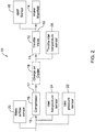
- Figure 2 provides another view of the illustrative air inlet system 10 of Figure 1 , with several sensors added as part of the engine management system.
- Many engines include a mass airflow sensor 20 that provides a mass flow rate for air entering the air inlet system 10, which may be used by an engine management system to determine a proper amount of fuel to add for proper combustion.
- An inlet pressure sensor 22 provides an indication of the air pressure upstream of the compressor 16. In some cases, this may provide an indication of ambient air pressure, but it will be recognized that ambient air pressure can vary with weather systems, altitude, temperature and other factors.
- An inlet temperature sensor 24 provides an indication of the air temperature of the air entering the compressor 16.
- a throttle inlet temperature sensor 26 provides an indication of the temperature of the air within the air inlet system 10 downstream of the compressor 16, near the air inlet 11 of the throttle valve 12.
- a Manifold Absolute Pressure (MAP) sensor 28 provides an indication of air pressure downstream of the throttle valve 12, such as at or in the intake manifold 14 of the engine.
- the MAP sensor 28 is commonly used on many modern engines for controlling the operation of the engine, such as controlling the operation of the fuel injectors (if present), engine timing, turbo speed, and/or other engine parameters.
- Figure 3 provides a view of the air inlet system 10, identifying some of the parameters useful in estimating turbocharger speed.
- the parameters shown in Figure 3 may be measured using the sensors identified in Figure 2 .
- Figure 3 also identifies parameters useful in estimating turbocharger speed that are not directly measured, but rather are calculated using the measured parameters.
- the parameter ⁇ C represents an uncorrected mass flow rate, and may be measured via, for example, the mass airflow sensor 20 (see Figure 2 ).
- the parameter T C,in represents a temperature of the air entering the air inlet 15 of the compressor 16, and may be measured using, for example, the inlet temperature sensor 24 (see Figure 2 ).
- the parameter p C,in represents a pressure of the air entering the air inlet 15 of the compressor 16, and may be measured using, for example, the inlet pressure sensor 22 (see, Figure 2 ).
- a corrected mass flow rate ⁇ C,Cor may be calculated using the uncorrected mass flow rate ⁇ C , p C,in , and T C,in .
- the parameter ⁇ T Downstream of the charge air cooler 18 (if present), the parameter ⁇ T is the mass flow rate through the throttle valve 12. In some cases, the parameter ⁇ T is not measured, but rather is set equal to the mass flow rate ⁇ C discussed above.
- the parameter p T,out represents the pressure at the outlet of the throttle valve 12 and may be measured by the MAP sensor 28.
- the parameter u T represents a throttle command signal, which may provide an indication of a commanded throttle position, or perhaps an actual throttle position if different from the commanded throttle position.
- the throttle command signal u T may be provided by an engine management system.
- the parameter p T,in which represents the pressure at the inlet of the throttle valve 12
- the parameter p C,out which represents the pressure at the air outlet 17 of the compressor 16, may in some cases be set equal to the parameter p T,in .
- these calculated parameters, and ultimately the turbocharger speed may be determined by simultaneously or sequentially solving several equations.
- the parameter p C,out may be calculated using a throttle model, which solves for the parameter p C,out .
- the throttle model solves for the compressor outlet pressure p C,out , which is then used to determine the compressor speed as discussed above using the turbocharger model expressed in Equation 1.
- ⁇ T p T , in p T , out ⁇ 1 ⁇ 2 ⁇ ⁇ ⁇ 1 1 ⁇ p T , in p T . out 1 ⁇ ⁇ ⁇ ⁇ In these equations, the following variables are utilized:
- the throttle input pressure p T.in is calculated using the throttle model (e.g. via Equation 2)
- the throttle input pressure p T.in is used as the compressor outlet pressure p C,out when determining the compressor speed using the illustrative turbocharger model expressed in Equation 1.
- FIG 4 is a schematic diagram of a controller 30 that may be used in combination with the air inlet system of Figure 1 to process the above-referenced parameters to calculate the turbocharger speed.
- the controller 30 may be a standalone controller or computer.
- the controller 30 may be manifested as a component of the aforementioned engine management system.
- the controller 30 may include an input port 32 and an output port 34.
- a processor 36 may be operatively coupled to the input port 32 and to the output port 34.
- a memory 38 may be coupled to the processor 36 and may, for example, store instructions that are executable by the processor 36 to estimate the speed of the compressor 16.
- the processor 36 may estimate the turbocharger speed within the confines of a unitary model.
- the processor 36 may estimate an air pressure at an outlet of the compressor 16 using a throttle model, and estimate the turbocharger speed using the air pressure provided by the throttle model in combination with a turbocharger model.
- the inputs to the input port 32 may include a compressor air flow signal 40 representing a measure of air flow through the compressor 16, a compressor air inlet pressure signal 42 representing a measure of pressure at the air inlet 15 of the compressor 16, an intake manifold pressure signal 44 representing a measure of pressure at the air intake manifold 14, and a throttle position signal 46 that represents the throttle position of the throttle valve 12.
- processor 36 utilizing the throttle model (e.g. Equation 2), estimates an air pressure at the air outlet 17 of the compressor 16 referencing at least the throttle signal and the measure of pressure at the air intake manifold 14 of the engine.
- the throttle model also references a measure of temperature of the air at the throttle valve 12. In some cases, the throttle model also references a measure of air flow through the compressor 16. In some instances, the throttle model models the effects of the charge air cooler 18, when present. In some cases, the throttle model further references a measure of a temperature of the air in the throttle valve 12, where the measure is taken downstream of the charge air cooler 18 and upstream of the throttle valve 12.
- the processor 36 of the controller 30, utilizing the turbocharger model estimates the operating speed of the turbocharger referencing at least the measure of air flow through the compressor 16, the measure of pressure at the air inlet 15 of the compressor 16 and the estimated air pressure at the air outlet 17 of the compressor 16 (e.g. as estimated by the throttle model).
- the turbocharger model also references a measure of temperature of the air at the air inlet 15 of the compressor 16.
- the turbocharger model further references one or more of the specific heat of air, the heat capacity of air and/or the specific gas constant of air.
- the processor 36 provides, via the output port 34, one or more control signals 48 that may be used to control an operation of the turbocharger and/or the engine in response to the estimated operating speed of the turbocharger.
- FIG. 6 is a flow diagram of an illustrative method for estimating an operating speed of a turbocharger that has a compressor 16 with an air inlet 15 and an air outlet 17.
- the compressor 16 feeds compressed air to a downstream throttle, such as the throttle valve 12, which provides a throttled air flow to an air intake manifold of an engine, such as the air intake manifold 14.
- the operating speed of the turbocharger may be estimated.
- the estimated operating speed of the turbocharger may be based, at least in part, upon one or more of a measure of air flow through the compressor 16, a measure of pressure at the air inlet 15 of the compressor 16, a measure of pressure at the air intake manifold 14 of the engine, and/or a throttle signal that represents the throttle position of the throttle.
- operation of the turbocharger and/or the engine may be controlled in response to the estimated operating speed of the turbocharger.
- estimating the operating speed of the turbocharger as referenced at block 50 may also be based on a measure of temperature of the air at the air inlet 15 of the compressor 16. In some cases, estimating the operating speed of the turbocharger as referenced at block 50 may also be based on a measure of temperature of the air at the throttle. In some cases, estimating the operating speed of the turbocharger as referenced at block 50 may also be based on a measure of temperature of the air at the air inlet of the compressor and a measure of temperature of the air at the throttle.
Landscapes
- Engineering & Computer Science (AREA)
- Chemical & Material Sciences (AREA)
- Combustion & Propulsion (AREA)
- Mechanical Engineering (AREA)
- General Engineering & Computer Science (AREA)
- Analytical Chemistry (AREA)
- Physics & Mathematics (AREA)
- Fluid Mechanics (AREA)
- Computer Hardware Design (AREA)
- Microelectronics & Electronic Packaging (AREA)
- General Physics & Mathematics (AREA)
- Supercharger (AREA)
- Combined Controls Of Internal Combustion Engines (AREA)
Abstract
Description
- The present disclosure pertains generally to automotive engine controls, and more particularly pertains to estimating the rotation speed of a turbocharger of the engine.
- The speed at which a turbocharger rotates is an important parameter in controlling operation of turbocharged engines. The maximum turbo speed may define a maximum achievable air flow, which in turn defines a maximum achievable torque of the engine. Exceeding the maximum turbo speed can lead to mechanical damage to the turbocharger and can ultimately lead to engine failure. A goal in controlling operation of some turbocharged engines, therefore, is the ability to achieve a high turbo speed without exceeding the maximum allowed speed.
- In some cases, the turbo speed may be directly measured by a dedicated speed sensor that may, for example, utilize blade counting or the like. This tends to be an expensive solution. In some cases, a less expensive alternative is to estimate the turbo speed using inputs from other sensors utilized in engine management. For example, the turbo speed may be estimated using mass air flow, compressor inlet pressure, compressor outlet pressure and compressor inlet temperature. In some cases, these values may be related via a compressor map in which the turbo speed may simply be looked up once the other values are measured and known.
- A shortcoming of this estimation method is that a compressor outlet pressure sensor must be placed at the output of the turbo's compressor. Most contemporary engine designs do not include a compressor outlet pressure sensor. Thus, the addition of the compressor outlet pressure sensor may increase the cost of the engine management system, and may even reduce the reliability of the system since there is an additional failure mechanism.
- Modern vehicles often include a Manifold Absolute Pressure (MAP) sensor for sensing the pressure at the intake manifold of the engine. The MAP sensor is often used to control the operation of the engine. The MAP sensor is typically located at the intake manifold of the engine, and for engines with a turbocharger, the MAP sensor is typically located downstream of the turbocharger's compressor outlet, and in most cases downstream of the engine's throttle valve. In some cases, a charge air cooler is disposed between the compressor outlet and the throttle valve. The charge air cooler, when provided, may cool the compressed air provided by the compressor in order to provide a more dense intake charge into the engine, which can increase the power output of the engine. The present disclosure relates to techniques for estimating the turbo speed of a turbocharger using data from a pressure sensor that is located downstream of the throttle valve, such as the MAP sensor, instead of a compressor outlet pressure sensor that is located at the output of the compressor. This approach may reduce the cost and increase the reliability of the engine management system.
- In a particular example of the present disclosure, a controller may be used to estimate an operating speed of a turbocharger that has a compressor with an air inlet and an air outlet. The compressor feeds compressed air to a downstream throttle that provides a throttled air flow to an air intake manifold of an engine. The controller may include an inlet port, an outlet port and a processor that is operatively coupled to the inlet port and the outlet port. In some cases, the inlet port may receive one or more of a compressor air flow signal that represents a measure of air flow through the compressor, a compressor air inlet pressure signal that represents a measure of pressure at the air inlet of the compressor, an intake manifold pressure signal that represents a measure of pressure at the air intake manifold of the engine, a temperature signal that represents the temperature of the air at the throttle, and a throttle signal that represents the throttle position of the throttle. In some cases, the controller may include a memory that stores instructions that are executable by the processor to estimate the operating speed of the turbocharger based at least in part on the values received by the inlet port. In some cases, the processor may provide one or more control signals via the output port to control an operation of the turbocharger and/or the engine in response to the estimated operating speed of the turbocharger.
- In another example of the present disclosure, a controller may be used to estimate an operating speed of a turbocharger that has a compressor with an air inlet and an air outlet. The compressor feeds compressed air to a downstream throttle that provides a throttled air flow to an air intake manifold of an engine. The controller may include an inlet port, an outlet port and a processor that is operatively coupled to the inlet port and the outlet port. In some cases, the inlet port may receive one or more of a compressor air flow signal that represents a measure of air flow through the compressor, a compressor air inlet pressure signal that represents a measure of pressure at the air inlet of the compressor, an intake manifold pressure signal that represents a measure of pressure at the air intake manifold of the engine and a throttle signal that represents the throttle position of the throttle. In some cases, the controller may include a memory that stores instructions that are executable by the processor to estimate an air pressure at the air outlet of the compressor using a throttle model that references at least the throttle signal and the measure of pressure at the air intake manifold of the engine. The controller may further estimate the operating speed of the turbocharger using a turbocharger model that references at least the measure of air flow through the compressor, the measure of pressure at the air inlet of the compressor and the estimated air pressure at the air outlet of the compressor. In some cases, the processor may provide one or more control signals via the output port to control an operation of the turbocharger and/or the engine in response to the estimated operating speed of the turbocharger.
- The above summary is not intended to describe each disclosed embodiment or every implementation of the present disclosure. The Figures, and Detailed Description, which follow, more particularly exemplify some of these embodiments.
- The disclosure may be more completely understood in consideration of the following detailed description in connection with the accompanying drawings, in which:
-
Figure 1 is a schematic diagram of an air inlet system of an engine encompassing a turbocharger in accordance with an illustrative embodiment of the present disclosure; -
Figure 2 is a schematic diagram of the air inlet system ofFigure 1 , with the addition of particular sensors; -
Figure 3 is a schematic diagram of the air inlet system ofFigure 1 , showing particular measured and estimated parameters; -
Figure 4 is a schematic diagram of a controller that may be used in combination with the air inlet system ofFigure 1 to estimate the turbocharger speed of the turbocharger; -
Figure 5 is a schematic diagram of the controller ofFigure 4 , showing illustrative inputs and outputs of the controller; and -
Figure 6 is a flow diagram showing an illustrative method of operating an engine and/or turbocharger. - While the disclosure is amenable to various modifications and alternative forms, specifics thereof have been shown by way of example in the drawings and will be described in detail. It should be understood, however, that the intention is not to limit the disclosure to the particular embodiments described. On the contrary, the intention is to cover all modifications, equivalents, and alternatives falling within the spirit and scope of the disclosure.
- For the following defined terms, these definitions shall be applied, unless a different definition is given in the claims or elsewhere in this specification.
- All numeric values are herein assumed to be modified by the term "about," whether or not explicitly indicated. The term "about" generally refers to a range of numbers that one of skill in the art would consider equivalent to the recited value (i.e., having the same function or result). In many instances, the terms "about" may include numbers that are rounded to the nearest significant figure.
- The recitation of numerical ranges by endpoints includes all numbers within that range (e.g. 1 to 5 includes 1, 1.5, 2, 2.75, 3, 3.80, 4, and 5).
- As used in this specification and the appended claims, the singular forms "a", "an", and "the" include plural referents unless the content clearly dictates otherwise. As used in this specification and the appended claims, the term "or" is generally employed in its sense including "and/or" unless the content clearly dictates otherwise.
- It is noted that references in the specification to "an embodiment", "some embodiments", "other embodiments", etc., indicate that the embodiment described may include one or more particular features, structures, and/or characteristics. However, such recitations do not necessarily mean that all embodiments include the particular features, structures, and/or characteristics. Additionally, when particular features, structures, and/or characteristics are described in connection with one embodiment, it should be understood that such features, structures, and/or characteristics may also be used connection with other embodiments whether or not explicitly described unless clearly stated to the contrary.
- The following description should be read with reference to the drawings in which similar structures in different drawings are numbered the same. The drawings, which are not necessarily to scale, depict illustrative embodiments and are not intended to limit the scope of the disclosure.
Figure 1 is a schematic illustration of anair inlet system 10 that may, for example, be used in combination with any suitable gasoline and/or diesel-powered engine. It will be appreciated that in some cases theair inlet system 10 may include additional components not shown inFigure 1 . As illustrated, theair inlet system 10 may include athrottle valve 12 that is positioned upstream of anair intake manifold 14. The throttle valve has anair inlet 11 and anair outlet 13. Air entering theair intake manifold 14 can be mixed with fuel and fed into the combustion chambers via one or more intake valves disposed atop each engine cylinder. In some engines, known as direct injection engines, fuel may be directly injected into each engine cylinder. In these engines, fuel is not mixed with air within theair intake manifold 14 itself. - In some cases, the
throttle valve 12 may be opened further, to provide additional air, or at least partially closed, to provide less air, in response to a throttle command signal emanating from an engine management system (not shown). The engine management system may provide a command signal to change the position of thethrottle valve 12 in response to the driver pushing harder on the accelerator pedal, or perhaps taking their foot off the accelerator pedal. In some cases, the engine management system may provide a throttle command signal to change the position of thethrottle valve 12 in order to maintain a desired speed in response to a cruise control system (not shown). While the engine management system is generally referenced herein as a unitary control structure, it will be appreciated that in actuality, the engine management system may include a number of distinct computers, controllers, processors, sensors and the like. - Moving upstream in the illustrative
air inlet system 10, air entering theair inlet system 10 is provided to acompressor 16 of a turbocharger. Thecompressor 16 includes anair inlet 15 and anair outlet 17. It will be appreciated thatcompressor 16 is disposed within the air intake flow. The turbocharger will typically also include a drive turbine (not shown) that is disposed within an exhaust gas flow of the engine. Gases within the exhaust flow cause the drive turbine to rotate. The drive turbine typically drives thecompressor 16 via a compressor drive shaft. Thecompressor 16, which is disposed within the air intake flow, rotates via the aforementioned shaft. As thecompressor 16 rotates, it draws air through theair inlet 15, compresses the air, and provides the compressed air to theair outlet 17. Air entering thecompressor 16 at theair inlet 15 is generally at or close to ambient pressure, while air exiting thecompressor 16 at theair outlet 17 is at an increased pressure relative to ambient pressure. The air passing through thecompressor 16 may be heated as a result of being compressed, as well through some engine heating. Accordingly, in some cases, while not required, acharge air cooler 18 may be disposed downstream of thecompressor 16 in order to cool the air before it reaches thethrottle valve 12 and theair intake manifold 14 of the engine. Thecharge air cooler 18, when provided, may cool the compressed air provided by thecompressor 16 in order to provide a more dense intake charge into the engine, which can increase the power output of the engine. -
Figure 2 provides another view of the illustrativeair inlet system 10 ofFigure 1 , with several sensors added as part of the engine management system. Many engines include amass airflow sensor 20 that provides a mass flow rate for air entering theair inlet system 10, which may be used by an engine management system to determine a proper amount of fuel to add for proper combustion. Aninlet pressure sensor 22 provides an indication of the air pressure upstream of thecompressor 16. In some cases, this may provide an indication of ambient air pressure, but it will be recognized that ambient air pressure can vary with weather systems, altitude, temperature and other factors. Aninlet temperature sensor 24 provides an indication of the air temperature of the air entering thecompressor 16. In the example shown, a throttleinlet temperature sensor 26 provides an indication of the temperature of the air within theair inlet system 10 downstream of thecompressor 16, near theair inlet 11 of thethrottle valve 12. A Manifold Absolute Pressure (MAP)sensor 28 provides an indication of air pressure downstream of thethrottle valve 12, such as at or in theintake manifold 14 of the engine. TheMAP sensor 28 is commonly used on many modern engines for controlling the operation of the engine, such as controlling the operation of the fuel injectors (if present), engine timing, turbo speed, and/or other engine parameters. -
Figure 3 provides a view of theair inlet system 10, identifying some of the parameters useful in estimating turbocharger speed. The parameters shown inFigure 3 may be measured using the sensors identified inFigure 2 .Figure 3 also identifies parameters useful in estimating turbocharger speed that are not directly measured, but rather are calculated using the measured parameters. Moving left to right inFigure 3 , the parameter ṁC represents an uncorrected mass flow rate, and may be measured via, for example, the mass airflow sensor 20 (seeFigure 2 ). The parameter TC,in represents a temperature of the air entering theair inlet 15 of thecompressor 16, and may be measured using, for example, the inlet temperature sensor 24 (seeFigure 2 ). The parameter pC,in represents a pressure of the air entering theair inlet 15 of thecompressor 16, and may be measured using, for example, the inlet pressure sensor 22 (see,Figure 2 ). A corrected mass flow rate ṁC,Cor may be calculated using the uncorrected mass flow rate ṁC , pC,in , and TC,in. Downstream of the charge air cooler 18 (if present), the parameter ṁT is the mass flow rate through thethrottle valve 12. In some cases, the parameter ṁT is not measured, but rather is set equal to the mass flow rate ṁC discussed above. - The parameter pT,out represents the pressure at the outlet of the
throttle valve 12 and may be measured by theMAP sensor 28. The parameter uT represents a throttle command signal, which may provide an indication of a commanded throttle position, or perhaps an actual throttle position if different from the commanded throttle position. The throttle command signal uT may be provided by an engine management system. - These measured parameters, along with several reference values as will be further detailed below, may be used to calculate additional parameters. For example, the parameter pT,in , which represents the pressure at the inlet of the
throttle valve 12, may be calculated. The parameter pC,out , which represents the pressure at theair outlet 17 of thecompressor 16, may in some cases be set equal to the parameter pT,in . In some cases, these calculated parameters, and ultimately the turbocharger speed, may be determined by simultaneously or sequentially solving several equations. - For example, in some cases the following turbocharger model expressed as a continuous function may be solved to calculate the turbocharger operating speed:


- In these equations, the following variables are defined, in addition to those discussed above:
- ṁC,Cor is the corrected compressor mass flow rate, which is based on an uncorrected mass flow rate ṁC that can be provided by a mass flow sensor positioned at the inlet of the compressor:

-

-

- UC is (corrected) blade tip speed πdC ṄT,Cor/60, where dC is the rotor wheel diameter.
- cp is the specific heat of dry throttle command air, which is approximately 1006 J / (kg K).
- γ is the heat capacity ratio of the air, which is approximately 1.4.
- R is the specific gas constant, which is approximately 287.058 J /(kg K) for the dry air.
- In some cases, there may not be a pressure sensor that is positioned at the
air outlet 17 of thecompressor 16 to provide a value for pC,out . Rather, in some cases, the parameter pC,out may be calculated using a throttle model, which solves for the parameter pC,out . The throttle model solves for the compressor outlet pressure pC,out , which is then used to determine the compressor speed as discussed above using the turbocharger model expressed in Equation 1. The following throttle model, expressed as a continuous function, may be solved to calculate the throttle input pressure pT.in :

- ṁT is the mass flow rate through the throttle valve, which is set equal to the mass flow rate through the compressor ṁC. As detailed above, ṁC is based on the output of a
mass airflow sensor 20 positioned at the inlet of thecompressor 16. - pT,in is the pressure at the
air inlet 11 of thethrottle valve 12, which is calculated by the throttle model (e.g. Equation 2). - In some cases, once the throttle input pressure pT.in is calculated using the throttle model (e.g. via Equation 2), the throttle input pressure pT.in is used as the compressor outlet pressure pC,out when determining the compressor speed using the illustrative turbocharger model expressed in Equation 1.
-
Figure 4 is a schematic diagram of acontroller 30 that may be used in combination with the air inlet system ofFigure 1 to process the above-referenced parameters to calculate the turbocharger speed. In some cases, thecontroller 30 may be a standalone controller or computer. In some cases, thecontroller 30 may be manifested as a component of the aforementioned engine management system. Thecontroller 30 may include aninput port 32 and anoutput port 34. Aprocessor 36 may be operatively coupled to theinput port 32 and to theoutput port 34. Amemory 38 may be coupled to theprocessor 36 and may, for example, store instructions that are executable by theprocessor 36 to estimate the speed of thecompressor 16. In some cases, theprocessor 36 may estimate the turbocharger speed within the confines of a unitary model. In some cases, theprocessor 36 may estimate an air pressure at an outlet of thecompressor 16 using a throttle model, and estimate the turbocharger speed using the air pressure provided by the throttle model in combination with a turbocharger model. - In
Figure 5 , it can be seen that there are several inputs to theinput port 32. For example, the inputs to theinput port 32 may include a compressorair flow signal 40 representing a measure of air flow through thecompressor 16, a compressor airinlet pressure signal 42 representing a measure of pressure at theair inlet 15 of thecompressor 16, an intakemanifold pressure signal 44 representing a measure of pressure at theair intake manifold 14, and athrottle position signal 46 that represents the throttle position of thethrottle valve 12. In some cases,processor 36, utilizing the throttle model (e.g. Equation 2), estimates an air pressure at theair outlet 17 of thecompressor 16 referencing at least the throttle signal and the measure of pressure at theair intake manifold 14 of the engine. In some cases, the throttle model also references a measure of temperature of the air at thethrottle valve 12. In some cases, the throttle model also references a measure of air flow through thecompressor 16. In some instances, the throttle model models the effects of thecharge air cooler 18, when present. In some cases, the throttle model further references a measure of a temperature of the air in thethrottle valve 12, where the measure is taken downstream of thecharge air cooler 18 and upstream of thethrottle valve 12. - In some cases, the
processor 36 of thecontroller 30, utilizing the turbocharger model (e.g. Equation 1), estimates the operating speed of the turbocharger referencing at least the measure of air flow through thecompressor 16, the measure of pressure at theair inlet 15 of thecompressor 16 and the estimated air pressure at theair outlet 17 of the compressor 16 (e.g. as estimated by the throttle model). In some cases, the turbocharger model also references a measure of temperature of the air at theair inlet 15 of thecompressor 16. In some instances, the turbocharger model further references one or more of the specific heat of air, the heat capacity of air and/or the specific gas constant of air. In some cases, theprocessor 36 provides, via theoutput port 34, one or more control signals 48 that may be used to control an operation of the turbocharger and/or the engine in response to the estimated operating speed of the turbocharger. -
Figure 6 is a flow diagram of an illustrative method for estimating an operating speed of a turbocharger that has acompressor 16 with anair inlet 15 and anair outlet 17. Thecompressor 16 feeds compressed air to a downstream throttle, such as thethrottle valve 12, which provides a throttled air flow to an air intake manifold of an engine, such as theair intake manifold 14. As generally referenced atblock 50, the operating speed of the turbocharger may be estimated. In some cases, the estimated operating speed of the turbocharger may be based, at least in part, upon one or more of a measure of air flow through thecompressor 16, a measure of pressure at theair inlet 15 of thecompressor 16, a measure of pressure at theair intake manifold 14 of the engine, and/or a throttle signal that represents the throttle position of the throttle. As generally referenced atblock 52, operation of the turbocharger and/or the engine may be controlled in response to the estimated operating speed of the turbocharger. - In some cases, estimating the operating speed of the turbocharger as referenced at
block 50 may also be based on a measure of temperature of the air at theair inlet 15 of thecompressor 16. In some cases, estimating the operating speed of the turbocharger as referenced atblock 50 may also be based on a measure of temperature of the air at the throttle. In some cases, estimating the operating speed of the turbocharger as referenced atblock 50 may also be based on a measure of temperature of the air at the air inlet of the compressor and a measure of temperature of the air at the throttle. - It should be understood that this disclosure is, in many respects, only illustrative. Changes may be made in details, particularly in matters of shape, size, and arrangement of steps without exceeding the scope of the disclosure. This may include, to the extent that it is appropriate, the use of any of the features of one example embodiment being used in other embodiments.

Claims (20)
- A controller for estimating an operating speed of a turbocharger that has a compressor with an air inlet and an air outlet, the compressor feeding compressed air to a downstream throttle that provides a throttled air flow to an air intake manifold of an engine, the controller comprising:an input port for receiving:a compressor air flow signal that represents a measure of air flow through the compressor;a compressor air inlet pressure signal that represents a measure of pressure at the air inlet of the compressor;an intake manifold pressure signal that represents a measure of pressure at the air intake manifold of the engine;a throttle signal that represents the throttle position of the throttle;an output port;a processor operatively coupled to the input port and the output port;memory having instructions stored therein that are executable by the processor to:estimate an air pressure at the air outlet of the compressor using a throttle model that references at least:the throttle signal; andthe measure of pressure at the air intake manifold of the engine;estimate the operating speed of the turbocharger using a turbocharger model that references at least:the measure of air flow through the compressor;the measure of pressure at the air inlet of the compressor; andthe estimated air pressure at the air outlet of the compressor; andprovide one or more control signals via the output port to control an operation of the turbocharger and/or the engine in response to the estimated operating speed of the turbocharger.
- The controller of claim 1, wherein the turbocharger model further references a measure of temperature of the air at the air inlet of the compressor.
- The controller of claim 1, wherein the turbocharger model further references the specific heat of air, the heat capacity ratio of air, and the specific gas constant of air.
- The controller of claim 1, wherein the throttle model further references a measure of temperature of the air at the throttle.
- The controller of claim 1, wherein the throttle model further references the measure of air flow through the compressor.
- The controller of claim 1, wherein a charge air cooler is interposed between the air outlet of the compressor and the downstream throttle, wherein the throttle model also models the effects of the charge air cooler.
- The controller of claim 6, wherein the throttle model further references a measure of temperature of the air in the throttle, wherein the measure of temperature is taken downstream of the charge air cooler and upstream of the throttle.
- The controller of claim 1, wherein the measure of pressure at the air intake manifold of the engine is provided by a Manifold Air Pressure (MAP) sensor.
- The controller of claim 1, wherein the measure of air flow through the compressor is provided by a flow sensor at the air inlet of the compressor.
- The controller of claim 1, wherein the measure of pressure at the air inlet of the compressor is provided by a pressure sensor at the air inlet of the compressor.
- A controller for estimating an operating speed of a turbocharger that has a compressor with an air inlet and an air outlet, the compressor feeding compressed air to a downstream throttle that provides a throttled air flow to an air intake manifold of an engine, the controller comprising:an input port for receiving:a compressor air flow signal that represents a measure of air flow through the compressor;a compressor air inlet pressure signal that represents a measure of pressure at the air inlet of the compressor;an intake manifold pressure signal that represents a measure of pressure at the air intake manifold of the engine;a throttle signal that represents the throttle position of the throttle;an output port;a processor operatively coupled to the input port and the output port;memory having instructions stored therein that are executable by the processor to:estimate the operating speed of the turbocharger based at least in part on:the measure of air flow through the compressor;the measure of pressure at the air inlet of the compressor;the measure of pressure at the air intake manifold of the engine;the throttle signal; andprovide one or more control signals via the output port to control an operation of the turbocharger and/or the engine in response to the estimated operating speed of the turbocharger.
- The controller of claim 11, wherein estimating the operating speed of the turbocharger is also based on a measure of temperature of the air at the air inlet of the compressor.
- The controller of claim 11, wherein estimating the operating speed of the turbocharger is also based on a measure of temperature of the air at the throttle.
- The controller of claim 11, wherein the measure of pressure at the air intake manifold of the engine is provided by a Manifold Air Pressure (MAP) sensor.
- The controller of claim 11, wherein the measure of air flow through the compressor is provided by a flow sensor at the air inlet of the compressor.
- The controller of claim 11, wherein the measure of pressure at the air inlet of the compressor is provided by a pressure sensor at the air inlet of the compressor.
- A method for estimating an operating speed of a turbocharger that has a compressor with an air inlet and an air outlet, the compressor feeding compressed air to a downstream throttle that provides a throttled air flow to an air intake manifold of an engine, the method comprising:estimating the operating speed of the turbocharger based at least in part on:a measure of air flow through the compressor;a measure of pressure at the air inlet of the compressor;a measure of pressure at the air intake manifold of the engine;a throttle signal that represents the throttle position of the throttle; and controlling an operation of the turbocharger and/or the engine in response to theestimated operating speed of the turbocharger.
- The method of claim 17, wherein the estimating the operating speed of the turbocharger is also based on a measure of temperature of the air at the air inlet of the compressor.
- The method of claim 17, wherein the estimated operating speed of the turbocharger is also based on a measure of temperature of the air at the throttle.
- The method of claim 17, wherein the estimated operating speed of the turbocharger is also based on a measure of temperature of the air at the air inlet of the compressor and a measure of temperature of the air at the throttle.
Applications Claiming Priority (1)
| Application Number | Priority Date | Filing Date | Title |
|---|---|---|---|
| US15/040,960 US11053875B2 (en) | 2016-02-10 | 2016-02-10 | System and method for estimating turbo speed of an engine |
Publications (2)
| Publication Number | Publication Date |
|---|---|
| EP3205863A1 true EP3205863A1 (en) | 2017-08-16 |
| EP3205863B1 EP3205863B1 (en) | 2026-03-04 |
Family
ID=57850955
Family Applications (1)
| Application Number | Title | Priority Date | Filing Date |
|---|---|---|---|
| EP17152074.5A Active EP3205863B1 (en) | 2016-02-10 | 2017-01-18 | System and method for estimating turbo speed of an engine |
Country Status (3)
| Country | Link |
|---|---|
| US (2) | US11053875B2 (en) |
| EP (1) | EP3205863B1 (en) |
| CN (2) | CN107061031B (en) |
Families Citing this family (5)
| Publication number | Priority date | Publication date | Assignee | Title |
|---|---|---|---|---|
| WO2019217625A1 (en) * | 2018-05-09 | 2019-11-14 | Abb Schweiz Ag | Breaker auto-synchronizer |
| CN110513720B (en) * | 2019-08-30 | 2020-12-08 | 中国航发动力股份有限公司 | a dual fuel system |
| CN111075579B (en) * | 2019-12-31 | 2022-08-05 | 一汽解放汽车有限公司 | Method and device for determining rotating speed of supercharger, vehicle and storage medium |
| US12060844B1 (en) | 2023-08-03 | 2024-08-13 | Garrett Transportation Inc. | Air-path coordination in an engine |
| CN117927395A (en) * | 2024-01-08 | 2024-04-26 | 山东大学 | Engine control method and system considering different working conditions |
Citations (4)
| Publication number | Priority date | Publication date | Assignee | Title |
|---|---|---|---|---|
| EP1837512A1 (en) * | 2005-01-11 | 2007-09-26 | Toyota Jidosha Kabushiki Kaisha | Internal combustion engine air volume estimation device |
| DE102008022083A1 (en) * | 2007-05-10 | 2008-11-13 | Ford Global Technologies, LLC, Dearborn | Compensation of overspeed of a turbocharger shaft |
| US20140034026A1 (en) * | 2011-04-18 | 2014-02-06 | Toyota Jidosha Kabushiki Kaisha | Control device for supercharged engine |
| US9010180B2 (en) * | 2012-01-10 | 2015-04-21 | Ford Global Technologies, Llc | Method and observer for determining the exhaust manifold temperature in a turbocharged engine |
Family Cites Families (65)
| Publication number | Priority date | Publication date | Assignee | Title |
|---|---|---|---|---|
| US6155050A (en) | 1999-06-01 | 2000-12-05 | Cummins Engine Co Inc | System and method for protecting a turbocharger in the event of a wastegate failure |
| DE10047405A1 (en) | 2000-09-26 | 2002-04-11 | Daimler Chrysler Ag | Turbocharger, in particular exhaust gas turbocharger for an internal combustion engine |
| US6401457B1 (en) | 2001-01-31 | 2002-06-11 | Cummins, Inc. | System for estimating turbocharger compressor outlet temperature |
| US6539714B1 (en) | 2002-03-19 | 2003-04-01 | Cummins, Inc. | System for estimating turbocharger rotational speed |
| US6804601B2 (en) | 2002-03-19 | 2004-10-12 | Cummins, Inc. | Sensor failure accommodation system |
| US6557347B1 (en) | 2002-10-31 | 2003-05-06 | General Electric Co. | Methods and apparatus for controlling peak firing pressure for turbo-charged diesel engines |
| DE10320977A1 (en) | 2003-05-09 | 2004-12-09 | Siemens Ag | Procedure for monitoring the speed of a bi-turbocharger |
| US7007472B2 (en) | 2004-02-10 | 2006-03-07 | Cummins, Inc. | System for limiting turbocharger rotational speed |
| SE0400466L (en) | 2004-02-26 | 2005-06-28 | Scania Cv Abp | Procedure and apparatus for speeding protection of a turbocharger in a vehicle |
| DE102004010263A1 (en) | 2004-03-03 | 2005-09-22 | Daimlerchrysler Ag | Method and device for speed detection of turbochargers |
| DE102004047116A1 (en) | 2004-03-08 | 2005-10-06 | Micro-Epsilon Messtechnik Gmbh & Co Kg | Method and device for non-contact speed measurement |
| JP4018071B2 (en) | 2004-03-30 | 2007-12-05 | 富士フイルム株式会社 | Optical fiber defect detection apparatus and method |
| US7127892B2 (en) | 2004-08-13 | 2006-10-31 | Cummins, Inc. | Techniques for determining turbocharger speed |
| DE102005008030A1 (en) | 2005-02-22 | 2006-03-09 | Daimlerchrysler Ag | Shaft rotation speed measuring mechanism for e.g. turbocharger, has detection unit detecting magnetic signal of magnets, where magnets magnetized in radial direction are arranged on both sides of shaft axis |
| AR052402A1 (en) | 2005-07-18 | 2007-03-21 | Vignolo Gustavo Gabriel | METHOD OF SPEED MEASUREMENT IN TURBO-INTERNAL COMBUSTION MOTOR FEEDERS BY VIBRATION ANALYSIS, SOFWARE AND EQUIPMENT TO PERFORM IT |
| JP2007113563A (en) * | 2005-09-26 | 2007-05-10 | Honda Motor Co Ltd | Control device for internal combustion engine |
| DE102005056517A1 (en) | 2005-11-28 | 2007-05-31 | Robert Bosch Gmbh | Compressor e.g. exhaust gas turbocharger, rotation speed determining method for use in e.g. diesel internal combustion engine, involves obtaining rotation speed of compressor from periodic fluctuation of portion of pressure signal |
| DE102006003599A1 (en) | 2006-01-25 | 2007-08-16 | Siemens Ag | Compressor housing for an exhaust gas turbocharger |
| US7296562B2 (en) | 2006-03-30 | 2007-11-20 | Caterpiller Inc. | Control system and method for estimating turbocharger performance |
| JP4502277B2 (en) | 2006-06-12 | 2010-07-14 | ヤンマー株式会社 | Engine with turbocharger |
| DE102006027422B4 (en) | 2006-06-13 | 2014-02-06 | Continental Automotive Gmbh | Method and device for monitoring an exhaust gas turbocharger |
| US20080053087A1 (en) | 2006-08-30 | 2008-03-06 | General Electric Company | System and Method for Detecting Impaired Operation of an Internal Combustion Engine Turbocharger |
| DE102006057318A1 (en) | 2006-12-05 | 2008-06-12 | Siemens Ag | Method and device for signal conditioning of sensor signals for inductive measurement of a turbocharger speed |
| GB0700148D0 (en) | 2007-01-05 | 2007-02-14 | Cummins Turbo Tech Ltd | A method and apparatus for detecting the rotational speed of a rotary member |
| WO2009028003A1 (en) | 2007-08-30 | 2009-03-05 | Honeywell International, Inc. | Use of post compressor bleed to control turbocharger overspeeding |
| US7748217B2 (en) | 2007-10-04 | 2010-07-06 | Delphi Technologies, Inc. | System and method for modeling of turbo-charged engines and indirect measurement of turbine and waste-gate flow and turbine efficiency |
| FR2922596B1 (en) | 2007-10-23 | 2010-02-26 | Renault Sas | METHOD AND SYSTEM FOR DYNAMICALLY ESTIMATING THE ROTATIONAL SPEED OF A TURBOCHARGER OF A COMBUSTION ENGINE. |
| US20090133399A1 (en) | 2007-11-27 | 2009-05-28 | Caterpillar Inc. | Turbocharger system implementing real time speed limiting |
| US7769522B2 (en) | 2008-02-29 | 2010-08-03 | Cummins Ip, Inc | Apparatus and method for preventing an underspeed event of a turbocharger |
| US8061137B2 (en) | 2008-05-30 | 2011-11-22 | Caterpillar Inc. | Fuel control system for limiting turbocharger speed |
| US7861580B2 (en) | 2008-06-23 | 2011-01-04 | Cummins Ip, Inc. | Virtual turbine speed sensor |
| FR2941267B1 (en) | 2009-01-22 | 2011-01-21 | Renault Sas | METHOD AND APPARATUS FOR DETERMINING THE PRESSURE BEFORE A TURBINE OF A TURBOCHARGER OF A THERMAL MOTOR. |
| DE102010003347B4 (en) | 2009-05-20 | 2021-08-05 | Robert Bosch Gmbh | Method and device for determining one or more speeds of a charging device, in particular for an internal combustion engine |
| US8397499B2 (en) * | 2009-08-24 | 2013-03-19 | Ford Global Technologies, Llc | Methods and systems for turbocharger control |
| US8387384B2 (en) * | 2009-09-22 | 2013-03-05 | GM Global Technology Operations LLC | Pressure estimation systems and methods |
| US8640459B2 (en) | 2009-10-23 | 2014-02-04 | GM Global Technology Operations LLC | Turbocharger control systems and methods for improved transient performance |
| US20120179356A1 (en) | 2010-02-09 | 2012-07-12 | Kazunari Ide | Control device for turbocharged engine |
| IT1400363B1 (en) | 2010-06-03 | 2013-05-31 | Magneti Marelli Spa | METHOD OF DETERMINING THE ROTATION SPEED OF A COMPRESSOR IN AN INTERNAL COMBUSTION ENGINE |
| IT1400362B1 (en) | 2010-06-03 | 2013-05-31 | Magneti Marelli Spa | METHOD OF DETERMINING THE ROTATION SPEED OF A COMPRESSOR IN AN INTERNAL COMBUSTION ENGINE |
| DE102010039532A1 (en) | 2010-08-19 | 2012-02-23 | Continental Automotive Gmbh | Rotation speed sensor arrangement for turbo supercharger in motor car, has coil element for detecting modulated magnetic field produced by rotation of magnetic encoder, to produce electrical energy for supply to circuits |
| DE102010060330A1 (en) | 2010-11-03 | 2012-05-03 | Ford Global Technologies, Llc. | Method for monitoring a pollutant concentration in the exhaust gas of an internal combustion engine |
| DE102011016489A1 (en) | 2011-04-08 | 2012-10-11 | Continental Automotive Gmbh | Method and device for measuring the rotational speed of a turbocompressor and motor vehicle |
| GB2493748A (en) | 2011-08-17 | 2013-02-20 | Gm Global Tech Operations Inc | Unit for estimating the rotational speed of a turbocharger |
| JP5719257B2 (en) | 2011-09-02 | 2015-05-13 | ダイムラー・アクチェンゲゼルシャフトDaimler AG | Supercharger control device |
| US8567192B2 (en) | 2011-09-25 | 2013-10-29 | Cummins, Inc. | System for controlling an air handling system including a dual-stage variable geometry turbocharger |
| US8892332B2 (en) | 2011-09-25 | 2014-11-18 | Cummins, Inc. | System and method for estimating turbocharger operating speed |
| DE102012200261A1 (en) | 2012-01-10 | 2013-07-11 | Robert Bosch Gmbh | Arrangement and method for detecting a rotational speed of a turbocharger |
| JP5645207B2 (en) | 2012-01-31 | 2014-12-24 | 株式会社電子応用 | Eddy current sensor and turbocharger rotation detection device using the same |
| JP5770657B2 (en) | 2012-03-01 | 2015-08-26 | ヤンマー株式会社 | engine |
| GB2499852B (en) | 2012-03-02 | 2018-09-26 | Cummins Ltd | Voltage converter |
| KR20150013598A (en) | 2012-05-11 | 2015-02-05 | 보르그워너 인코퍼레이티드 | Exhaust-gas turbocharger |
| JP6032966B2 (en) | 2012-06-27 | 2016-11-30 | 日野自動車株式会社 | Turbo speed detector |
| DE102012211425A1 (en) | 2012-07-02 | 2014-01-23 | Robert Bosch Gmbh | Method for determining a speed of a compressor |
| DE102012213961A1 (en) | 2012-08-07 | 2014-03-06 | Robert Bosch Gmbh | Device for determining rotation speed of e.g. turbo supercharger of gasoline engine of motor car, has adapter including resilient clutch and fastened to compressor by resilient clutch that is partly made of acoustic absorbing material |
| US9353760B2 (en) | 2012-08-17 | 2016-05-31 | Borg Warner Inc. | Speed sensor insert with bearing spacer indexing for a turbocharger |
| US9341150B2 (en) | 2012-11-06 | 2016-05-17 | GM Global Technology Operations LLC | Throttle control systems and methods for reducing induction noise |
| DE102012222202A1 (en) | 2012-12-04 | 2014-06-05 | Robert Bosch Gmbh | Method for monitoring a rotation of a compressor wheel |
| CN105518467B (en) | 2013-08-29 | 2020-10-30 | 杰凯特技术集团股份公司 | Sensor device and turbocharger having the same |
| GB2519515A (en) | 2013-10-14 | 2015-04-29 | Gm Global Tech Operations Inc | Method of estimating the boost capability of a turbocharged internal combustion engine |
| US9303553B2 (en) | 2013-12-05 | 2016-04-05 | GM Global Technology Operations LLC | Turbo speed control for mode transitions in a dual turbo system |
| JP6036677B2 (en) | 2013-12-26 | 2016-11-30 | トヨタ自動車株式会社 | Electric wastegate valve system |
| JP5734478B1 (en) * | 2014-02-25 | 2015-06-17 | 三菱電機株式会社 | Control device for an internal combustion engine with a supercharger |
| US9617931B2 (en) | 2014-04-07 | 2017-04-11 | MAGNETI MARELLI S.p.A. | Method to control a supercharged internal combustion engine provided with a turbocharger by means of an estimation of the average power delivered by the turbine of the turbocharger |
| DE102014019470A1 (en) | 2014-12-23 | 2016-06-23 | Doc Ag | Slatted base with a variety of mounting bodies for mounting spring connectors |
| GB2541201A (en) * | 2015-08-11 | 2017-02-15 | Gm Global Tech Operations Llc | Method of operating a turbocharged automotive system |
-
2016
- 2016-02-10 US US15/040,960 patent/US11053875B2/en active Active
-
2017
- 2017-01-18 EP EP17152074.5A patent/EP3205863B1/en active Active
- 2017-02-10 CN CN201710073671.4A patent/CN107061031B/en active Active
- 2017-02-10 CN CN202210177699.3A patent/CN114517745A/en not_active Withdrawn
-
2021
- 2021-06-08 US US17/342,222 patent/US20210293193A1/en not_active Abandoned
Patent Citations (4)
| Publication number | Priority date | Publication date | Assignee | Title |
|---|---|---|---|---|
| EP1837512A1 (en) * | 2005-01-11 | 2007-09-26 | Toyota Jidosha Kabushiki Kaisha | Internal combustion engine air volume estimation device |
| DE102008022083A1 (en) * | 2007-05-10 | 2008-11-13 | Ford Global Technologies, LLC, Dearborn | Compensation of overspeed of a turbocharger shaft |
| US20140034026A1 (en) * | 2011-04-18 | 2014-02-06 | Toyota Jidosha Kabushiki Kaisha | Control device for supercharged engine |
| US9010180B2 (en) * | 2012-01-10 | 2015-04-21 | Ford Global Technologies, Llc | Method and observer for determining the exhaust manifold temperature in a turbocharged engine |
Also Published As
| Publication number | Publication date |
|---|---|
| US20170226948A1 (en) | 2017-08-10 |
| US11053875B2 (en) | 2021-07-06 |
| CN107061031A (en) | 2017-08-18 |
| EP3205863B1 (en) | 2026-03-04 |
| CN107061031B (en) | 2022-02-15 |
| US20210293193A1 (en) | 2021-09-23 |
| CN114517745A (en) | 2022-05-20 |
Similar Documents
| Publication | Publication Date | Title |
|---|---|---|
| US20210293193A1 (en) | System and method for estimating turbo speed of an engine | |
| US8417484B2 (en) | Method and device for monitoring an intercooler bypass valve | |
| US9309826B2 (en) | Method and device for ascertaining a modeling value for a physical variable in an engine system having an internal combustion engine | |
| US11098662B2 (en) | Compressor override control | |
| US10041427B2 (en) | Sensor output value estimation device | |
| US20150377156A1 (en) | Control apparatus for an internal combustion engine | |
| CN104863699B (en) | The control device of the internal combustion engine with booster | |
| US10480432B2 (en) | Exhaust gas recirculation valves for a forced-induction internal combustion engine with exhaust gas recirculation | |
| US9482169B2 (en) | Optimization-based controls for diesel engine air-handling systems | |
| US8677748B2 (en) | Fresh air flow estimation | |
| JP5865942B2 (en) | Cylinder intake air amount estimation apparatus and method for internal combustion engine | |
| CN113530666B (en) | Method for regulating and controlling rotating speed of turbocharger | |
| CN107269407B (en) | Method and apparatus for determining fresh air mass flow in a combustion motor | |
| US8285496B2 (en) | Method and device for providing air mass flow information in a supercharged internal combustion engine | |
| CN100532810C (en) | Method and device for operating an internal combustion engine | |
| JP2007205339A (en) | Turbocharger state quantity estimation device | |
| CN102192813A (en) | Method and apparatus for determining analogue value of pressure in engine system with internal combustion engine | |
| CA2408780C (en) | Air flow target determination | |
| JP2013155613A (en) | Control device of turbocharged engine | |
| JP4665843B2 (en) | Abnormality determination device for internal combustion engine | |
| MXPA06002538A (en) | Method for determining a temperature downstream the entry of a catalytic converter for a turbocharged engine. | |
| JP7430114B2 (en) | Internal combustion engine control device | |
| JP2013155614A (en) | Control device of turbocharged engine |
Legal Events
| Date | Code | Title | Description |
|---|---|---|---|
| PUAI | Public reference made under article 153(3) epc to a published international application that has entered the european phase |
Free format text: ORIGINAL CODE: 0009012 |
|
| STAA | Information on the status of an ep patent application or granted ep patent |
Free format text: STATUS: REQUEST FOR EXAMINATION WAS MADE |
|
| 17P | Request for examination filed |
Effective date: 20170118 |
|
| AK | Designated contracting states |
Kind code of ref document: A1 Designated state(s): AL AT BE BG CH CY CZ DE DK EE ES FI FR GB GR HR HU IE IS IT LI LT LU LV MC MK MT NL NO PL PT RO RS SE SI SK SM TR |
|
| AX | Request for extension of the european patent |
Extension state: BA ME |
|
| STAA | Information on the status of an ep patent application or granted ep patent |
Free format text: STATUS: EXAMINATION IS IN PROGRESS |
|
| 17Q | First examination report despatched |
Effective date: 20180508 |
|
| RAP1 | Party data changed (applicant data changed or rights of an application transferred) |
Owner name: GARRETT TRANSPORTATION I INC. |
|
| P01 | Opt-out of the competence of the unified patent court (upc) registered |
Effective date: 20230424 |
|
| GRAP | Despatch of communication of intention to grant a patent |
Free format text: ORIGINAL CODE: EPIDOSNIGR1 |
|
| STAA | Information on the status of an ep patent application or granted ep patent |
Free format text: STATUS: GRANT OF PATENT IS INTENDED |
|
| INTG | Intention to grant announced |
Effective date: 20251219 |
|
| GRAS | Grant fee paid |
Free format text: ORIGINAL CODE: EPIDOSNIGR3 |
|
| GRAA | (expected) grant |
Free format text: ORIGINAL CODE: 0009210 |
|
| STAA | Information on the status of an ep patent application or granted ep patent |
Free format text: STATUS: THE PATENT HAS BEEN GRANTED |
|
| AK | Designated contracting states |
Kind code of ref document: B1 Designated state(s): AL AT BE BG CH CY CZ DE DK EE ES FI FR GB GR HR HU IE IS IT LI LT LU LV MC MK MT NL NO PL PT RO RS SE SI SK SM TR |
|
| REG | Reference to a national code |
Ref country code: CH Ref legal event code: F10 Free format text: ST27 STATUS EVENT CODE: U-0-0-F10-F00 (AS PROVIDED BY THE NATIONAL OFFICE) Effective date: 20260304 Ref country code: GB Ref legal event code: FG4D |
|
| REG | Reference to a national code |
Ref country code: IE Ref legal event code: FG4D |
|
| REG | Reference to a national code |
Ref country code: DE Ref legal event code: R096 Ref document number: 602017094122 Country of ref document: DE |
|
| PG25 | Lapsed in a contracting state [announced via postgrant information from national office to epo] |
Ref country code: RS Free format text: LAPSE BECAUSE OF FAILURE TO SUBMIT A TRANSLATION OF THE DESCRIPTION OR TO PAY THE FEE WITHIN THE PRESCRIBED TIME-LIMIT Effective date: 20260604 |
|
| PG25 | Lapsed in a contracting state [announced via postgrant information from national office to epo] |
Ref country code: ES Free format text: LAPSE BECAUSE OF FAILURE TO SUBMIT A TRANSLATION OF THE DESCRIPTION OR TO PAY THE FEE WITHIN THE PRESCRIBED TIME-LIMIT Effective date: 20260304 |
|
| REG | Reference to a national code |
Ref country code: NL Ref legal event code: MP Effective date: 20260304 |
|
| PG25 | Lapsed in a contracting state [announced via postgrant information from national office to epo] |
Ref country code: PL Free format text: LAPSE BECAUSE OF FAILURE TO SUBMIT A TRANSLATION OF THE DESCRIPTION OR TO PAY THE FEE WITHIN THE PRESCRIBED TIME-LIMIT Effective date: 20260304 |
|
| PG25 | Lapsed in a contracting state [announced via postgrant information from national office to epo] |
Ref country code: GR Free format text: LAPSE BECAUSE OF FAILURE TO SUBMIT A TRANSLATION OF THE DESCRIPTION OR TO PAY THE FEE WITHIN THE PRESCRIBED TIME-LIMIT Effective date: 20260605 |
|
| REG | Reference to a national code |
Ref country code: LT Ref legal event code: MG9D |
|
| PG25 | Lapsed in a contracting state [announced via postgrant information from national office to epo] |
Ref country code: LT Free format text: LAPSE BECAUSE OF FAILURE TO SUBMIT A TRANSLATION OF THE DESCRIPTION OR TO PAY THE FEE WITHIN THE PRESCRIBED TIME-LIMIT Effective date: 20260304 |
|
| PG25 | Lapsed in a contracting state [announced via postgrant information from national office to epo] |
Ref country code: NO Free format text: LAPSE BECAUSE OF FAILURE TO SUBMIT A TRANSLATION OF THE DESCRIPTION OR TO PAY THE FEE WITHIN THE PRESCRIBED TIME-LIMIT Effective date: 20260604 |
|
| PG25 | Lapsed in a contracting state [announced via postgrant information from national office to epo] |
Ref country code: FI Free format text: LAPSE BECAUSE OF FAILURE TO SUBMIT A TRANSLATION OF THE DESCRIPTION OR TO PAY THE FEE WITHIN THE PRESCRIBED TIME-LIMIT Effective date: 20260304 Ref country code: SE Free format text: LAPSE BECAUSE OF FAILURE TO SUBMIT A TRANSLATION OF THE DESCRIPTION OR TO PAY THE FEE WITHIN THE PRESCRIBED TIME-LIMIT Effective date: 20260304 |
|
| PG25 | Lapsed in a contracting state [announced via postgrant information from national office to epo] |
Ref country code: HR Free format text: LAPSE BECAUSE OF FAILURE TO SUBMIT A TRANSLATION OF THE DESCRIPTION OR TO PAY THE FEE WITHIN THE PRESCRIBED TIME-LIMIT Effective date: 20260304 |
|
| PG25 | Lapsed in a contracting state [announced via postgrant information from national office to epo] |
Ref country code: LV Free format text: LAPSE BECAUSE OF FAILURE TO SUBMIT A TRANSLATION OF THE DESCRIPTION OR TO PAY THE FEE WITHIN THE PRESCRIBED TIME-LIMIT Effective date: 20260304 |
|
| PG25 | Lapsed in a contracting state [announced via postgrant information from national office to epo] |
Ref country code: BG Free format text: LAPSE BECAUSE OF FAILURE TO SUBMIT A TRANSLATION OF THE DESCRIPTION OR TO PAY THE FEE WITHIN THE PRESCRIBED TIME-LIMIT Effective date: 20260304 |