EP3205835B1 - Bowed rotor start using direct temperature measurement - Google Patents
Bowed rotor start using direct temperature measurement Download PDFInfo
- Publication number
- EP3205835B1 EP3205835B1 EP17155683.0A EP17155683A EP3205835B1 EP 3205835 B1 EP3205835 B1 EP 3205835B1 EP 17155683 A EP17155683 A EP 17155683A EP 3205835 B1 EP3205835 B1 EP 3205835B1
- Authority
- EP
- European Patent Office
- Prior art keywords
- gas turbine
- turbine engine
- motoring
- rotor
- speed
- Prior art date
- Legal status (The legal status is an assumption and is not a legal conclusion. Google has not performed a legal analysis and makes no representation as to the accuracy of the status listed.)
- Active
Links
Images


Classifications
-
- F—MECHANICAL ENGINEERING; LIGHTING; HEATING; WEAPONS; BLASTING
- F02—COMBUSTION ENGINES; HOT-GAS OR COMBUSTION-PRODUCT ENGINE PLANTS
- F02C—GAS-TURBINE PLANTS; AIR INTAKES FOR JET-PROPULSION PLANTS; CONTROLLING FUEL SUPPLY IN AIR-BREATHING JET-PROPULSION PLANTS
- F02C7/00—Features, components parts, details or accessories, not provided for in, or of interest apart form groups F02C1/00 - F02C6/00; Air intakes for jet-propulsion plants
- F02C7/26—Starting; Ignition
-
- F—MECHANICAL ENGINEERING; LIGHTING; HEATING; WEAPONS; BLASTING
- F01—MACHINES OR ENGINES IN GENERAL; ENGINE PLANTS IN GENERAL; STEAM ENGINES
- F01D—NON-POSITIVE DISPLACEMENT MACHINES OR ENGINES, e.g. STEAM TURBINES
- F01D19/00—Starting of machines or engines; Regulating, controlling, or safety means in connection therewith
- F01D19/02—Starting of machines or engines; Regulating, controlling, or safety means in connection therewith dependent on temperature of component parts, e.g. of turbine-casing
-
- F—MECHANICAL ENGINEERING; LIGHTING; HEATING; WEAPONS; BLASTING
- F01—MACHINES OR ENGINES IN GENERAL; ENGINE PLANTS IN GENERAL; STEAM ENGINES
- F01D—NON-POSITIVE DISPLACEMENT MACHINES OR ENGINES, e.g. STEAM TURBINES
- F01D25/00—Component parts, details, or accessories, not provided for in, or of interest apart from, other groups
- F01D25/34—Turning or inching gear
- F01D25/36—Turning or inching gear using electric motors
-
- F—MECHANICAL ENGINEERING; LIGHTING; HEATING; WEAPONS; BLASTING
- F02—COMBUSTION ENGINES; HOT-GAS OR COMBUSTION-PRODUCT ENGINE PLANTS
- F02C—GAS-TURBINE PLANTS; AIR INTAKES FOR JET-PROPULSION PLANTS; CONTROLLING FUEL SUPPLY IN AIR-BREATHING JET-PROPULSION PLANTS
- F02C3/00—Gas-turbine plants characterised by the use of combustion products as the working fluid
- F02C3/04—Gas-turbine plants characterised by the use of combustion products as the working fluid having a turbine driving a compressor
-
- F—MECHANICAL ENGINEERING; LIGHTING; HEATING; WEAPONS; BLASTING
- F02—COMBUSTION ENGINES; HOT-GAS OR COMBUSTION-PRODUCT ENGINE PLANTS
- F02C—GAS-TURBINE PLANTS; AIR INTAKES FOR JET-PROPULSION PLANTS; CONTROLLING FUEL SUPPLY IN AIR-BREATHING JET-PROPULSION PLANTS
- F02C7/00—Features, components parts, details or accessories, not provided for in, or of interest apart form groups F02C1/00 - F02C6/00; Air intakes for jet-propulsion plants
- F02C7/26—Starting; Ignition
- F02C7/268—Starting drives for the rotor, acting directly on the rotor of the gas turbine to be started
-
- F—MECHANICAL ENGINEERING; LIGHTING; HEATING; WEAPONS; BLASTING
- F02—COMBUSTION ENGINES; HOT-GAS OR COMBUSTION-PRODUCT ENGINE PLANTS
- F02C—GAS-TURBINE PLANTS; AIR INTAKES FOR JET-PROPULSION PLANTS; CONTROLLING FUEL SUPPLY IN AIR-BREATHING JET-PROPULSION PLANTS
- F02C9/00—Controlling gas-turbine plants; Controlling fuel supply in air- breathing jet-propulsion plants
-
- G—PHYSICS
- G01—MEASURING; TESTING
- G01H—MEASUREMENT OF MECHANICAL VIBRATIONS OR ULTRASONIC, SONIC OR INFRASONIC WAVES
- G01H1/00—Measuring characteristics of vibrations in solids by using direct conduction to the detector
- G01H1/003—Measuring characteristics of vibrations in solids by using direct conduction to the detector of rotating machines
-
- F—MECHANICAL ENGINEERING; LIGHTING; HEATING; WEAPONS; BLASTING
- F05—INDEXING SCHEMES RELATING TO ENGINES OR PUMPS IN VARIOUS SUBCLASSES OF CLASSES F01-F04
- F05D—INDEXING SCHEME FOR ASPECTS RELATING TO NON-POSITIVE-DISPLACEMENT MACHINES OR ENGINES, GAS-TURBINES OR JET-PROPULSION PLANTS
- F05D2220/00—Application
- F05D2220/30—Application in turbines
- F05D2220/32—Application in turbines in gas turbines
- F05D2220/323—Application in turbines in gas turbines for aircraft propulsion, e.g. jet engines
-
- F—MECHANICAL ENGINEERING; LIGHTING; HEATING; WEAPONS; BLASTING
- F05—INDEXING SCHEMES RELATING TO ENGINES OR PUMPS IN VARIOUS SUBCLASSES OF CLASSES F01-F04
- F05D—INDEXING SCHEME FOR ASPECTS RELATING TO NON-POSITIVE-DISPLACEMENT MACHINES OR ENGINES, GAS-TURBINES OR JET-PROPULSION PLANTS
- F05D2260/00—Function
- F05D2260/85—Starting
-
- F—MECHANICAL ENGINEERING; LIGHTING; HEATING; WEAPONS; BLASTING
- F05—INDEXING SCHEMES RELATING TO ENGINES OR PUMPS IN VARIOUS SUBCLASSES OF CLASSES F01-F04
- F05D—INDEXING SCHEME FOR ASPECTS RELATING TO NON-POSITIVE-DISPLACEMENT MACHINES OR ENGINES, GAS-TURBINES OR JET-PROPULSION PLANTS
- F05D2260/00—Function
- F05D2260/94—Functionality given by mechanical stress related aspects such as low cycle fatigue [LCF] of high cycle fatigue [HCF]
- F05D2260/941—Functionality given by mechanical stress related aspects such as low cycle fatigue [LCF] of high cycle fatigue [HCF] particularly aimed at mechanical or thermal stress reduction
-
- F—MECHANICAL ENGINEERING; LIGHTING; HEATING; WEAPONS; BLASTING
- F05—INDEXING SCHEMES RELATING TO ENGINES OR PUMPS IN VARIOUS SUBCLASSES OF CLASSES F01-F04
- F05D—INDEXING SCHEME FOR ASPECTS RELATING TO NON-POSITIVE-DISPLACEMENT MACHINES OR ENGINES, GAS-TURBINES OR JET-PROPULSION PLANTS
- F05D2270/00—Control
- F05D2270/50—Control logic embodiments
- F05D2270/54—Control logic embodiments by electronic means, e.g. electronic tubes, transistors or IC's within an electronic circuit
Definitions
- This disclosure relates to gas turbine engines, and more particularly to an apparatus, system and method for mitigating a bowed rotor start condition using direct temperature measurement in a gas turbine engine.
- Gas turbine engines are used in numerous applications, one of which is for providing thrust to an airplane.
- the gas turbine engine of an airplane has been shut off for example, after an airplane has landed at an airport, the engine is hot and due to heat rise, the upper portions of the engine will be hotter than lower portions of the engine. When this occurs thermal expansion may cause deflection of components of the engine which may result in a "bowed rotor" condition. If a gas turbine engine is in such a "bowed rotor" condition it is undesirable to restart or start the engine.
- EP 2305986 discloses a method for mitigating distortion of a gas turbine shaft.
- US 2012/0316748 and US 4453407 disclose methods of monitoring a gas turbine.
- a bowed rotor start mitigation system for a gas turbine engine, the bowed rotor start mitigation system comprising: a controller configured to receive a speed input indicative of a rotor speed from a speed pickup (122) of the gas turbine engine and a measured temperature of the gas turbine engine from a temperature sensor (134), the controller further configured to drive motoring of the gas turbine engine by oscillating the rotor speed to continuously rotate within a motoring band for a motoring time based on the measured temperature when a start sequence of the gas turbine engine is initiated and prior to determining that bowed rotor mitigation is complete.
- the motoring band includes a range of speeds below a resonance speed of the gas turbine engine.
- the measured temperature is adjusted with respect to a measured ambient temperature of the gas turbine engine.
- the motoring time is associated with a bowed rotor risk parameter that is determined based on the measured temperature.
- the measured temperature is determined based on reading one or more temperature sensors of the gas turbine engine for a predetermined period of time when the start sequence of the gas turbine engine is initiated.
- the controller is operable to monitor the vibration level while sweeping through a range of rotor speeds including a critical rotor speed and determine whether bowed rotor mitigation was successful prior to starting the gas turbine engine.
- the measured temperature is determined based on reading data from one or more temperature sensors at station 3 of the gas turbine engine.
- the measured temperature is determined based on reading data from one or more temperature sensors at station 4 of the gas turbine engine.
- the measured temperature is determined based on reading data from one or more temperature sensors at station 4.5 of the gas turbine engine.
- a gas turbine engine system includes a motoring system operable to drive rotation of the gas turbine engine, and the bowed rotor start mitigation system as discussed above, wherein the controller is an electronic engine control configured to drive motoring of the gas turbine engine by controlling the motoring system; wherein the motoring band preferably comprises a range of speeds above zero revolutions per minute and below a resonance speed of the gas turbine engine and the measured temperature is preferably adjusted with respect to a measured ambient temperature of the gas turbine engine.
- a method of bowed rotor start mitigation for a gas turbine engine comprising: receiving, by a controller, a speed input indicative of a rotor speed of the gas turbine engine; receiving, by the controller, a measured temperature of the gas turbine engine; and driving, by the controller, motoring of the gas turbine engine by oscillating the rotor speed to continuously rotate within a motoring band for a motoring time based on the measured temperature when a start sequence of the gas turbine engine is initiated and prior to determining that bowed rotor mitigation is complete.
- the motoring band comprises a range of speeds below a resonance speed of the gas turbine engine.
- the measured temperature is adjusted with respect to a measured ambient temperature of the gas turbine engine.
- the motoring time is associated with a bowed rotor risk parameter that is determined based on the measured temperature.
- the measured temperature is determined based on reading one or more temperature sensors of the gas turbine engine for a predetermined period of time when the start sequence of the gas turbine engine is initiated.
- the controller is operable to monitor the vibration level while sweeping through a range of rotor speeds including a critical rotor speed and determine whether bowed rotor mitigation was successful prior to starting the gas turbine engine.
- the measured temperature is determined based on reading data from one or more temperature sensors at station 3 of the gas turbine engine.
- the measured temperature is determined based on reading data from one or more temperature sensors at station 4 of the gas turbine engine.
- the measured temperature is determined based on reading data from one or more temperature sensors at station 4.5 of the gas turbine engine.
- a technical effect of the apparatus, systems and methods is achieved by using a start sequence for a gas turbine engine as described herein.
- Embodiments are related to a bowed rotor start mitigation system in a gas turbine engine.
- Embodiments can include using a measured temperature value of the gas turbine engine to estimate heat stored in the engine core when a start sequence is initiated and identify a risk of a bowed rotor.
- the measured temperature value alone or in combination with other values can be used to calculate a bowed rotor risk parameter.
- the measured temperature can be adjusted relative to an ambient temperature when calculating the bowed rotor risk parameter.
- the bowed rotor risk parameter may be used to take a control action to mitigate the risk of starting the gas turbine engine with a bowed rotor.
- the control action can include dry motoring, which may be performed by running an engine starting system at a lower speed with a longer duration than typically used for engine starting.
- dry motoring speed referred to herein is a speed below a major resonance speed where, if the temperatures are unhomogenized, the combination of the bowed rotor and similarly bowed casing and the resonance speed would lead to high amplitude oscillation in the rotor and high rubbing of blade tips on one side of the rotor, especially in the high pressure compressor if the rotor is straddle-mounted.
- the engine speed during dry motoring may oscillate within a motoring band of speed by modulating a starter valve, for example.
- Some embodiments increase the rotor speed of the starting spool to approach a critical rotor speed gradually according to a dry motoring profile and as thermal distortion is decreased they then accelerate beyond the critical rotor speed to complete the engine starting process.
- a full authority digital engine control (FADEC) system or other system may send a message to the cockpit to inform the crew of an extended time start time due to bowed rotor mitigation actions prior to completing an engine start sequence. If the engine is in a ground test or in a test stand, a message can be sent to the test stand or cockpit based on the control-calculated risk of a bowed rotor.
- a test stand crew can be alerted regarding a requirement to keep the starting spool of the engine to a speed below the known resonance speed of the rotor in order to homogenize the temperature of the rotor and the casings about the rotor which also are distorted by temperature non-uniformity.
- Monitoring of vibration signatures during the engine starting sequence can also or separately be used to assess the risk that a bowed rotor start has occurred due to some system malfunction and then direct maintenance, for instance, in the case of suspected outer air seal rub especially in the high compressor.
- Vibration data for the engine can also be monitored after bowed rotor mitigation is performed during an engine start sequence to confirm success of bowed rotor mitigation. If bowed rotor mitigation is unsuccessful or determined to be incomplete by the FADEC, resulting metrics (e.g., time, date, global positioning satellite (GPS) coordinates, vibration level vs. time, etc.) of the attempted bowed rotor mitigation can be recorded and/or transmitted to direct maintenance.
- GPS global positioning satellite
- a starter air pressure valve can be modulated or otherwise dynamically adjusted to limit high rotor speed below high spool resonance speed and prevent rub during dry motoring operation.
- the bowed rotor risk parameter can also be used to limit dry motoring duration to reduce the impact on air starter turbine life.
- the monitoring of vibration signatures during the entire engine starting sequence can also or separately be used to assess the risk of a bowed rotor start and direct maintenance, for instance, in the case of suspected outer air seal rub especially in the high compressor.
- the gas turbine engine 10 has among other components a fan through which ambient air is propelled into the engine housing, a compressor for pressurizing the air received from the fan and a combustor wherein the compressed air is mixed with fuel and ignited for generating combustion gases.
- the gas turbine engine 10 further comprises a turbine section for extracting energy from the combustion gases. Fuel is injected into the combustor of the gas turbine engine 10 for mixing with the compressed air from the compressor and ignition of the resultant mixture.
- the fan, compressor, combustor, and turbine are typically all concentric about a central longitudinal axis of the gas turbine engine 10.
- thermal deflection of the components of the gas turbine engine 10 may create the aforementioned bowing or "bowed rotor" condition along the common central longitudinal axis of the gas turbine engine 10 and thus it is desirable to clear or remove the bowed condition prior to the starting or restarting of the gas turbine engine 10.
- FIG. 1 schematically illustrates a gas turbine engine 10 that can be used to power an aircraft, for example.
- the gas turbine engine 10 is disclosed herein as a multi-spool turbofan that generally incorporates a fan section 22, a compressor section 24, a combustor section 26 and a turbine section 28.
- the fan section 22 drives air along a bypass flowpath while the compressor section 24 drives air along a core flowpath for compression and communication into the combustor section 26 then expansion through the turbine section 28.
- turbofan gas turbine engine in the disclosed non-limiting embodiment with two turbines and is sometimes referred to as a two spool engine
- the concepts described herein are not limited to use with turbofans as the teachings may be applied to other types of turbine engines including three-spool architectures.
- the starting spool is that spool that is located around the combustor, meaning the compressor part of the starting spool is flowing directly into the combustor and the combustor flows directly into the turbine section.
- the engine 10 generally includes a low speed spool 30 and a high speed spool 32 mounted for rotation about an engine central longitudinal axis A relative to an engine static structure 36 via several bearing systems 38. It should be understood that various bearing systems 38 at various locations may alternatively or additionally be provided.
- the low speed spool 30 generally includes an inner shaft 40 that interconnects a fan 42, a low pressure compressor 44 and a low pressure turbine 46.
- the inner shaft 40 is connected to the fan 42 through a geared architecture 48 to drive the fan 42 at a lower speed than the low speed spool 30 in the example of FIG. 1 .
- the high speed spool 32 includes an outer shaft 50 that interconnects a high pressure compressor 52 and high pressure turbine 54.
- a combustor 56 is arranged between the high pressure compressor 52 and the high pressure turbine 54.
- a mid-turbine frame 57 of the engine static structure 36 is arranged generally between the high pressure turbine 54 and the low pressure turbine 46.
- the mid-turbine frame 57 further supports bearing systems 38 in the turbine section 28.
- the inner shaft 40 and the outer shaft 50 are concentric and rotate via bearing systems 38 about the engine central longitudinal axis A which is collinear with their longitudinal axes.
- the core airflow is compressed by the low pressure compressor 44 then the high pressure compressor 52, mixed and burned with fuel in the combustor 56, then expanded over the high pressure turbine 54 and low pressure turbine 46.
- the mid-turbine frame 57 includes airfoils 59 which are in the core airflow path.
- the turbines 46, 54 rotationally drive the respective low speed spool 30 and high speed spool 32 in response to the expansion.
- Station 2 is at an inlet of low pressure compressor 44 having a temperature T2 and a pressure P2.
- Station 2.5 is at an exit of the low pressure compressor 44 having a temperature T2.5 and a pressure P2.5.
- Station 3 is at an inlet of the combustor 56 having a temperature T3 and a pressure P3.
- Station 4 is at an exit of the combustor 56 having a temperature T4 and a pressure P4.
- Station 4.5 is at an exit of the high pressure turbine 54 having a temperature T4.5 and a pressure P4.5.
- Station 5 is at an exit of the low pressure turbine 46 having a temperature T5 and a pressure P5.
- Measured temperatures in embodiments may be acquired at one or more stations 2-5.
- temperature T3 at station 3 can be used to as an engine rotor temperature measurement when there is no engine rotation.
- temperature values at stations 4 (T4), 4.5 (T4.5), and/or 5 (T5) can be used as an engine rotor temperature.
- Temperature measurements can be normalized to account for hot day/cold day differences.
- temperature T2 can be used as an ambient temperature and a measured temperature (e.g., T3) can be normalized by subtracting temperature T2.
- FIG. 1 depicts one example configuration
- embodiments as described herein can cover a wide range of configurations.
- embodiments may be implemented in a configuration that is described as a "straddle-mounted" spool 32A of FIG. 9 .
- This configuration places two bearing compartments 37A and 39A (which may include a ball bearing and a roller bearing respectively), outside of the plane of most of the compressor disks of high pressure compressor 52A and at outside at least one of the turbine disks of high pressure turbine 54A.
- other embodiments may be implemented using an over-hung mounted spool 32B as depicted in FIG. 10 .
- a bearing compartment 37B is located forward of the first turbine disk of high pressure turbine 54B such that the high pressure turbine 54B is overhung, and it is physically located aft of its main supporting structure.
- the use of straddle-mounted spools has advantages and disadvantages in the design of a gas turbine, but one characteristic of the straddle-mounted design is that the span between the bearing compartments 37A and 39A is long, making the amplitude of the high spot of a bowed rotor greater and the resonance speed that cannot be transited prior to temperature homogenization is lower.
- the straddle mounted arrangement such as straddle-mounted spool 32A
- the overhung mounted arrangement such as overhung spool 32B
- Lsupport is the distance between bearings (e.g., between bearing compartments 37A and 39A or between bearing compartments 37B and 39B)
- Dhpt is the diameter of the last blade of the high pressure turbine (e.g., high pressure turbine 54A or high pressure turbine 54B).
- FIGS. 9 and 10 also illustrate a starter 120 interfacing via a tower shaft 55 with the straddle-mounted spool 32A proximate high compressor 52A and interfacing via tower shaft 55 with the overhung mounted spool 32B proximate high compressor 52B as part of a starting system.
- the starting system 100 is also referred to generally as a gas turbine engine system.
- the starting system 100 includes a controller 102 which may be an electronic engine control, such as a dual-channel FADEC, and/or engine health monitoring unit.
- the controller 102 may include memory to store instructions that are executed by one or more processors.
- the executable instructions may be stored or organized in any manner and at any level of abstraction, such as in connection with a controlling and/or monitoring operation of the engine 10 of FIG. 1 .
- the one or more processors can be any type of central processing unit (CPU), including a general purpose processor, a digital signal processor (DSP), a microcontroller, an application specific integrated circuit (ASIC), a field programmable gate array (FPGA), or the like.
- the memory may include random access memory (RAM), read only memory (ROM), or other electronic, optical, magnetic, or any other computer readable medium onto which is stored data and control algorithms in a non-transitory form.
- the starting system 100 can also include a data storage unit (DSU) 104 that retains data between shutdowns of the gas turbine engine 10 of FIG. 1 .
- the DSU 104 includes non-volatile memory and retains data between cycling of power to the controller 102 and DSU 104.
- a communication link 106 can include an aircraft and/or test stand communication bus to interface with aircraft controls, e.g., a cockpit, various onboard computer systems, and/or a test stand.
- a motoring system 108 is operable to drive rotation of a starting spool (e.g., high speed spool 32) of the gas turbine engine 10 of FIG. 1 .
- Either or both channels of controller 102 can alternate on and off commands to an electromechanical device 110 coupled to a discrete starter valve 116A to achieve a partially open position of the discrete starter valve 116A to control a flow from a starter air supply 114 (also referred to as air supply 114) through a transfer duct 118 to an air turbine starter 120 (also referred to as starter 120 or pneumatic starter motor 120) to drive rotation of a starting spool of the gas turbine engine 10 below an engine idle speed.
- the air supply 114 (also referred to as starter air supply 114) can be provided by any known source of compressed air, such as an auxiliary power unit or ground cart.
- the controller 102 can monitor a speed sensor, such as speed pickup 122 that may sense the speed of the engine rotor through its connection to a gearbox 124 which is in turn connected to the high speed spool 32 via tower shaft 55 (e.g., rotational speed of high speed spool 32) or any other such sensor for detecting or determining the speed of the gas turbine engine 10 of FIG. 1 .
- the starter 120 may be coupled to the gearbox 124 of the gas turbine engine 10 of FIG. 1 directly or through a transmission such as a clutch system (not depicted).
- the controller 102 can establish a control loop with respect to rotor speed to adjust positioning of the discrete starter valve 116A.
- the discrete starter valve 116A is an embodiment of a starter valve that is designed as an on/off valve which is typically commanded to either fully opened or fully closed. However, there is a time lag to achieve the fully open position and the fully closed position.
- intermediate positioning states i.e., partially opened/closed
- the controller 102 can modulate the on and off commands (e.g., as a duty cycle using pulse width modulation) to the electromechanical device 110 to further open the discrete starter valve 116A and increase a rotational speed of the starting spool of the gas turbine engine 10 of FIG. 1 .
- the electromechanical device 110 has a cycle time defined between an off-command to an on-command to the off-command that is at most half of a movement time for the discrete starter valve 116A to transition from fully closed to fully open.
- Pneumatic lines 112A and 112B or a mechanical linkage can be used to drive the discrete starter valve 116A between the open position and the closed position.
- the electromechanical device 110 can be a solenoid that positions the discrete starter valve 116A based on intermittently supplied electric power as commanded by the controller 102.
- the electromechanical device 110 is an electric valve controlling muscle air to adjust the position of the discrete starter valve 116A as commanded by the controller 102.
- the starting system 100 also includes a vibration monitoring system 126.
- the vibration monitoring system 126 includes at least one vibration pickup 128, e.g., an accelerometer, operable to monitor vibration of the gas turbine engine 10 of FIG. 1 .
- Vibration signal processing 130 can be performed locally with respect to the vibration pickup 128, within the controller 102, or through a separate vibration processing system, which may be part of an engine health monitoring system to acquire vibration data 132.
- the vibration monitoring system 126 can be omitted in some embodiments.
- One or more temperature sensors 134 can provide measured temperatures at associated locations of the gas turbine engine 10 to the controller 102.
- the temperature sensors 134 can be located at station 2 (T2), station 2.5 (T2.5), station 3 (T3), station 4 (T4), station 4.5 (T4.5), and/or station 5 (T5) as previously described with respect to FIG. 1 .
- FIG. 3 is a schematic illustration of a starting system 100A for the gas turbine engine 10 of FIG. 1 in accordance with another embodiment.
- the starting system 100A includes controller 102 that controls motoring system 108A, as an alternate embodiment of the motoring system 108 of FIG. 2 .
- the motoring system 108A of FIG. 3 uses a variable position starter valve 116B.
- FIG. 1 In FIG. 1
- either or both channels of controller 102 can output a valve control signal 150 operable to dynamically adjust a valve angle of the variable position starter valve 116A that selectively allows a portion of the air supply 114 to pass through the variable position starter valve 116B and transfer duct 118 to air turbine starter 120.
- the variable position starter valve 116B is a continuous/infinitely adjustable valve that can hold a commanded valve angle, which may be expressed in terms of a percentage open/closed and/or an angular value (e.g., degrees or radians). Performance parameters of the variable position starter valve 116B can be selected to meet dynamic response requirements of the starting system 100A.
- variable position starter valve 116B has a response rate of 0% to 100% open in less than 40 seconds. In other embodiments, the variable position starter valve 116B has a response rate of 0% to 100% open in less than 30 seconds. In further embodiments, the variable position starter valve 116B has a response rate of 0% to 100% open in less than 20 seconds.
- the controller 102 can monitor a valve angle of the variable position starter valve 116B using valve angle feedback signals 152 provided to both channels of controller 102.
- both channels of the controller 102 can use the valve angle feedback signals 152 to track a current valve angle, while only one channel designated as an active channel outputs valve control signal 150.
- the standby channel of controller 102 can take over as the active channel to output valve control signal 150.
- both channels of controller 102 output all or a portion of a valve angle command simultaneously on the valve control signals 150.
- the controller 102 can establish an outer control loop with respect to rotor speed and an inner control loop with respect to the valve angle of the variable position starter valve 116B.
- One or more temperature sensors 134 such as thermocouples, can provide measured temperatures at associated locations of the gas turbine engine 10 to the controller 102.
- the starting system 100A of FIG. 3 also includes vibration monitoring system 126.
- the vibration monitoring system 126 includes at least one vibration pickup 128, e.g., an accelerometer, operable to monitor vibration of the gas turbine engine 10 of FIG. 1 .
- Vibration signal processing 130 can be performed locally with respect to the vibration pickup 128, within the controller 102, or through a separate vibration processing system, which may be part of an engine health monitoring system to acquire vibration data 132.
- the vibration monitoring system 126 can be omitted in some embodiments.
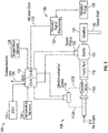
- FIG. 4 is a block diagram of a system 200 for bowed rotor start mitigation using direct temperature measurement that may control the discrete starter valve 116A of FIG. 2 or the variable position starter valve 116B of FIG. 3 via control signals 210 in accordance with an embodiment.
- the system 200 may also be referred to as a bowed rotor start mitigation system.
- the system 200 includes sensor processing 202 operable to acquire and condition data from a variety of sensors such as the speed pickup 122, vibration pickup 128, and temperature sensors 134 of FIG. 2 .
- the sensor processing 202 may also provide valve angle 207 to motoring controller 208 based on the valve angle feedback 152 of FIG. 3 .
- sensor processing 202 provides compressor exit temperature T3 and ambient temperature T2 to core temperature processing 204.
- one or more temperature values from stations 4 (T4), 4.5 (T4.5), and/or 5 (T5) can be provided to core temperature processing 204.
- Sensor processing 202 can provide rotor speed N2 (i.e., speed of high speed spool 32) to a motoring controller 208 and a mitigation monitor 214.
- Sensor processing 202 may also provide vibration data 132 to mitigation monitor 214.
- the sensor processing 202, core temperature processing 204, motoring controller 208, and/or mitigation monitor 214 may be part of controller 102.
- the heat state of the engine 10 or T core is determined by the core temperature processing 204.
- the compressor exit temperature T3 may be substantially equal to T core .
- T core is set equal to T3 - T2 to adjust the temperature with respect to the measured ambient temperature of the gas turbine engine 10. Further, temperature readings from other stations of the gas turbine engine 10 can be used to determine T core .
- Communication link 106 can provide the core temperature processing 204 with an indication 205 that a start sequence of the gas turbine engine 10 has been initiated. Once rotation of the gas turbine engine 10 begins, temperature readings can be collected for a predetermined period of time, such as ten seconds.
- the temperature readings can be averaged as core temperature T core before the temperature starts to change due to air flow from engine rotation.
- the core temperature processing 204 can determine a bowed rotor risk parameter that is based on the measured temperature using a mapping function or lookup table.
- the bowed rotor risk parameter can have an associated motoring time defining an anticipated amount of time for the motoring controller 208 to send control signals 210 to electromechanical device 110 for controlling discrete starter valve 116A of FIG. 2 or a dry motoring profile to control valve control signals 150 for controlling variable position starter valve 116B of FIG. 3 .
- a higher risk of a bowed rotor may result in a longer duration of dry motoring or an extended dry motoring profile to reduce a temperature gradient prior to starting the gas turbine engine 10 of FIG. 1 .
- the bowed rotor risk parameter may be quantified according to a profile curve 402 selected from a family of curves 404 that align with observed aircraft/engine conditions that impact turbine bore temperature (e.g., starting spool temperature) and the resulting bowed rotor risk as depicted in the example graph 400 of FIG. 6 .
- motoring of the engine 10 in a modified start sequence refers to the turning of a starting spool by the starter 120 at a reduced speed without introduction of fuel and an ignition source in order to cool the engine 10 to a point wherein a normal start sequence can be implemented without starting the engine 10 in a bowed rotor state.
- cool or ambient air is drawn into the engine 10 while motoring the engine 10 at a reduced speed in order to clear the "bowed rotor" condition, which is referred to as a dry motoring mode.
- the motoring controller 208 uses a dynamic control calculation in order to determine a required valve position of the starter valve 116A, 116B used to supply an air supply or starter air supply 114 to the engine 10 in order to limit the motoring speed of the engine 10 to a target speed N target within a motoring band or following a dry motoring profile due to the position of the starter valve 116A, 116B.
- the required valve position of the starter valve 116A, 116B can be determined based upon an air supply pressure as well as other factors including but not limited to ambient air temperature, parasitic drag on the engine 10 from a variety of engine driven components such as electric generators and hydraulic pumps, and other variables such that the motoring controller 208 closes the loop for an engine motoring speed target N target for the required amount of time based on the output of the bowed rotor start risk model 206.
- the dynamic control of the valve position (e.g., open state of the valve (e.g., fully open, 1 ⁇ 2 open, 1 ⁇ 4 open, etc.) in order to limit the motoring speed of the engine 10) is controlled via duty cycle control (on/off timing using pulse width modulation) of electromechanical device 110 for discrete starter valve 116A.
- a graph 450 illustrating starting profiles of a normal start 452 and a bowed rotor mitigation sequence start 454 is depicted according to an embodiment.
- the controller 102 of FIG. 2 opens discrete starter valve 116A of FIG. 2 (or variable position starter valve 116B of FIG. 3 ) to enable the air supply 114 to drive rotation of starter 120 to get rotor speed N2 of the gas turbine engine 10 up to idle speed 456.
- the controller 102 of FIG. 2 opens discrete starter valve 116A of FIG. 2 (or variable position starter valve 116B of FIG. 3 ) to enable the air supply 114 to drive rotation of starter 120 to get rotor speed N2 of the gas turbine engine 10 up to idle speed 456.
- controller 102 monitors one or more temperature sensors 134 for a predetermined period of time 458 while rotor speed N2 is at or about zero RPM. If core temperature processing 204 of FIG. 4 determines that bowed rotor mitigation is needed based on measured temperature, then bowed rotor mitigation sequence start 454 is performed instead of normal start 452.
- bowed rotor mitigation sequence start 454 oscillates the rotor speed N2 within a motoring band 460 for a motoring time.
- the motoring band 460 can be defined between a starter valve close limit 462 (i.e., an upper N2 speed limit) and a starter valve re-open limit 464 (i.e., a lower N2 limit).
- the starter valve close limit 462 is about 3000 RPM and the starter valve re-open limit 464 is about 2000 RPM.
- the actual values used for the starter valve close limit 462 and the starter valve re-open limit 464 can be tuned to the specific performance characteristics of the gas turbine engine 10 as further described with respect to FIG. 8 .
- an anticipated amount of dry motoring time can be used to determine a target rotor speed profile in a dry motoring profile for the currently observed conditions.
- one or more baseline characteristic curves for the target rotor speed profile can be defined in tables or according to functions that may be rescaled to align with the observed conditions.
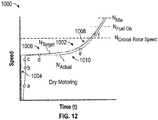
- An example of a target rotor speed profile 1002 is depicted in graph 1000 of FIG. 12 that includes a steep initial transition portion 1004, followed by a gradually increasing portion 1006, and a late acceleration portion 1008 that increases rotor speed above a critical rotor speed, through a fuel-on speed and an engine idle speed.
- the target rotor speed profile 1002 can be rescaled with respect to time and/or select portions (e.g., portions 1004, 1006, 1008) of the target rotor speed profile 1002 can be individually or collectively rescaled (e.g., slope changes) with respect to time to extend or reduce the total motoring time.
- the target rotor speed profile 1002 may include all positive slope values such that the actual rotor speed 1010 is driven to essentially increase continuously while bowed rotor start mitigation is active. While the example of FIG. 12 depicts one example of the target rotor speed profile 1002 that can be defined in a dry motoring profile, it will be understood that many variations are possible in embodiments.
- FIG. 11 illustrates how a valve angle command 902 can be adjusted between 0 to 100% of a commanded starter valve opening to generate the actual rotor speed 1010 of FIG. 12 .
- the valve angle command 902 transitions through points "a" and "b” to fully open the variable position starter valve 116B.
- the valve angle command 902 is reduced between points "b" and "c” to prevent the actual rotor speed 1010 from overshooting the target rotor speed profile 1002.
- decisions to increase or decrease the commanded starter valve opening is based on monitoring a rate of change of the actual rotor speed 1010 and projecting whether the actual rotor speed 1010 will align with the target rotor speed profile 1002 at a future time. If it is determined that the actual rotor speed 1010 will not align with the target rotor speed profile 1002 at a future time, then the valve angle of the variable position starter valve 116B is adjusted (e.g., increase or decrease the valve angle command 902) at a corresponding time. In the example of FIGS.
- the valve angle command 902 oscillates with a gradually reduced amplitude between points "c", “d”, and “e” as the actual rotor speed 1010 tracks to the target rotor speed profile 1002 through the gradually increasing portion 1006.
- the valve angle command transitions from point “e” to point "f' and beyond to further increase the actual rotor speed 1010 in the late acceleration portion 1008 above the critical rotor speed, through a fuel-on speed and an engine idle speed.
- the mitigation monitor 214 of FIG. 4 can operate in response to receiving a complete indicator 212 to run a verification of the bowed rotor mitigation.
- the mitigation monitor 214 can provide mitigation results 216 to the motoring controller 208 and may provide result metrics 218 to other systems, such a maintenance request or indicator. Peak vibrations can be checked by the mitigation monitor 214 during the start processes to confirm that bowed rotor mitigation successfully removed the bowed rotor condition.
- the mitigation monitor 214 may also run while dry motoring is active to determine whether adjustments to the dry motoring profile are needed.
- the mitigation monitor 214 can request that the motoring controller 208 reduce a slope of the target rotor speed profile 1002 of FIG. 12 to extend the dry motoring time before driving the actual rotor speed 1010 of FIG. 12 up to the critical rotor speed.
- the mitigation monitor 214 can request that the motoring controller 208 increase a slope of the target rotor speed profile 1002 of FIG. 12 to reduce the dry motoring time before driving the actual rotor speed 1010 of FIG. 12 up to the critical rotor speed.
- FIG. 5 is a flow chart illustrating a method 300 of bowed rotor start mitigation using direct temperature measurement of a gas turbine engine in accordance with an embodiment.
- the method 300 of FIG. 5 is described in reference to FIGS. 1-12 and may be performed with an alternate order and include additional steps.
- the controller 102 receives receive a speed input indicative of a rotor speed (e.g., N2) of the gas turbine engine 10.
- the speed input may be directly or indirectly indicative of the rotational speed of high speed spool 32, for instance, derived from a rotational speed of gearbox 124, from speed pickup 122, or another source (not depicted).
- the controller 102 receives a measured temperature from a temperature sensor 134.
- the measured temperature can be determined based on reading one or more temperature sensors 134 of the gas turbine engine 10 for a predetermined period of time when a start sequence of the gas turbine engine is initiated (e.g., based on indication 205).
- the measured temperature may be adjusted with respect to a measured ambient temperature of the gas turbine engine 10 (e.g., T3 - T2, T4 - T2, etc.).
- bowed rotor start mitigation can be performed using motoring system 108, 108A to rotate a starting spool of the gas turbine engine 10.
- the controller 102 can drive motoring of the gas turbine engine 10 by controlling the motoring system 108, 108A to oscillate the rotor speed (e.g., N2) within a motoring band for a motoring time based on the measured temperature when a start sequence of the gas turbine engine 10 is initiated.
- the motoring band can include a range of speeds below a resonance speed of the gas turbine engine 10.
- the motoring time can be associated with a bowed rotor risk parameter that is determined based on the measured temperature.
- other motoring profiles can be used, such as the target rotor speed profile 1002 for controlling starting spool speed during dry motoring.
- the controller 102 can monitor the vibration level of the gas turbine engine 10 while sweeping through a range of rotor speeds including a critical rotor speed and determine whether bowed rotor mitigation was successful prior to starting the gas turbine engine 10.
- the mitigation monitor 214 may receive a complete indicator 212 from the motoring controller 208 when the motoring controller 208 has completed dry motoring, for instance, if the motoring time has elapsed. If the mitigation monitor 214 determines that the bowed rotor condition still exists based on vibration data 132 collected, the motoring controller 208 may restart dry motoring, or a maintenance request or indicator can be triggered along with providing result metrics 218 for further analysis. Metrics of attempted bowed rotor mitigation can be recorded in the DSU 104 based on determining that the attempted bowed rotor mitigation was unsuccessful or incomplete.
- FIG. 8 is a graph illustrating examples of various vibration level profiles 502 of an engine, such as gas turbine engine 10 of FIG. 1 .
- the vibration level profiles 502 represent a variety of possible vibration levels observed before and/or after performing bowed rotor mitigation.
- a critical speed 510 is the speed at which a vibration peak is expected due to amplification effects of a bowed rotor condition along with other contributions to vibration level generally.
- a peak vibration 504 at critical rotor speed 510 may be used to trigger different events. For example, if the peak vibration 504 at critical rotor speed 510 is below a maintenance action threshold 506, then no further actions may be needed.
- a maintenance request is triggered based on the actual vibration level exceeding maintenance action threshold 506 after completing an attempt of bowed rotor mitigation.
- the lowest rotor vibration vs. speed in FIG. 8 is for a fully homogenized rotor, where mitigation is not necessary (engine parked all night long, for example).
- the next higher curve shows a mildly bowed rotor and so on.
- the maintenance action threshold 506 is a threshold for setting a maintenance flag such as requiring a troubleshooting routine of one or more system elements.
- the damage risk threshold 508 may be a threshold to trigger a more urgent maintenance requirement up to and including an engine check.
- the motoring band 460 is defined for a range of N2 rotor speeds below the critical speed 510 and such that the worst case expected vibration 512 is below the maintenance action threshold 506 within the motoring band 460.
- Performing motoring at a higher speed (e.g., 2000 to 3000 RPM) but less than the critical speed 510 can reduce the time needed for the temperature homogenization process while also avoiding vibrations reaching potentially harmful levels.
- the controller 102 may be programmed to automatically take the necessary measures in order to provide for a modified start sequence without pilot intervention other than the initial start request.
- the controller 102 and/or DSU 104 comprises a microprocessor, microcontroller or other equivalent processing device capable of executing commands of computer readable data or program for executing a control algorithm and/or algorithms that control the start sequence of the gas turbine engine.
- the controller 102 and/or DSU 104 may include, but not be limited to, a processor(s), computer(s), memory, storage, register(s), timing, interrupt(s), communication interfaces, and input/output signal interfaces, as well as combinations comprising at least one of the foregoing.
- the controller 102 and/or DSU 104 may include input signal filtering to enable accurate sampling and conversion or acquisitions of such signals from communications interfaces.
- exemplary embodiments of the disclosure can be implemented through computer-implemented processes and apparatuses for practicing those processes.
Description
- This disclosure relates to gas turbine engines, and more particularly to an apparatus, system and method for mitigating a bowed rotor start condition using direct temperature measurement in a gas turbine engine.
- Gas turbine engines are used in numerous applications, one of which is for providing thrust to an airplane. When the gas turbine engine of an airplane has been shut off for example, after an airplane has landed at an airport, the engine is hot and due to heat rise, the upper portions of the engine will be hotter than lower portions of the engine. When this occurs thermal expansion may cause deflection of components of the engine which may result in a "bowed rotor" condition. If a gas turbine engine is in such a "bowed rotor" condition it is undesirable to restart or start the engine.
- Accordingly, it is desirable to provide a method and/or apparatus for detecting and preventing a "bowed rotor" condition.
EP 2305986 discloses a method for mitigating distortion of a gas turbine shaft.US 2012/0316748 andUS 4453407 disclose methods of monitoring a gas turbine. - According to a first aspect of the invention, there is provided a bowed rotor start mitigation system for a gas turbine engine, the bowed rotor start mitigation system comprising: a controller configured to receive a speed input indicative of a rotor speed from a speed pickup (122) of the gas turbine engine and a measured temperature of the gas turbine engine from a temperature sensor (134), the controller further configured to drive motoring of the gas turbine engine by oscillating the rotor speed to continuously rotate within a motoring band for a motoring time based on the measured temperature when a start sequence of the gas turbine engine is initiated and prior to determining that bowed rotor mitigation is complete.
- In addition to one or more of the features described above, or as an alternative to any of the foregoing embodiments, in further embodiments the motoring band includes a range of speeds below a resonance speed of the gas turbine engine.
- In addition to one or more of the features described above, or as an alternative to any of the foregoing embodiments, in further embodiments the measured temperature is adjusted with respect to a measured ambient temperature of the gas turbine engine.
- In addition to one or more of the features described above, or as an alternative to any of the foregoing embodiments, in further embodiments the motoring time is associated with a bowed rotor risk parameter that is determined based on the measured temperature.
- In addition to one or more of the features described above, or as an alternative to any of the foregoing embodiments, in further embodiments the measured temperature is determined based on reading one or more temperature sensors of the gas turbine engine for a predetermined period of time when the start sequence of the gas turbine engine is initiated.
- In addition to one or more of the features described above, or as an alternative to any of the foregoing embodiments, in further embodiments, based on determining that bowed rotor mitigation is complete, the controller is operable to monitor the vibration level while sweeping through a range of rotor speeds including a critical rotor speed and determine whether bowed rotor mitigation was successful prior to starting the gas turbine engine.
- In addition to one or more of the features described above, or as an alternative to any of the foregoing embodiments, in further embodiments the measured temperature is determined based on reading data from one or more temperature sensors at station 3 of the gas turbine engine.
- In addition to one or more of the features described above, or as an alternative to any of the foregoing embodiments, in further embodiments the measured temperature is determined based on reading data from one or more temperature sensors at station 4 of the gas turbine engine.
- In addition to one or more of the features described above, or as an alternative to any of the foregoing embodiments, in further embodiments the measured temperature is determined based on reading data from one or more temperature sensors at station 4.5 of the gas turbine engine.
- According to an embodiment, a gas turbine engine system includes a motoring system operable to drive rotation of the gas turbine engine, and the bowed rotor start mitigation system as discussed above, wherein the controller is an electronic engine control configured to drive motoring of the gas turbine engine by controlling the motoring system; wherein the motoring band preferably comprises a range of speeds above zero revolutions per minute and below a resonance speed of the gas turbine engine and the measured temperature is preferably adjusted with respect to a measured ambient temperature of the gas turbine engine.
- According to a further aspect of the invention, there is provided a method of bowed rotor start mitigation for a gas turbine engine, the method comprising: receiving, by a controller, a speed input indicative of a rotor speed of the gas turbine engine; receiving, by the controller, a measured temperature of the gas turbine engine; and driving, by the controller, motoring of the gas turbine engine by oscillating the rotor speed to continuously rotate within a motoring band for a motoring time based on the measured temperature when a start sequence of the gas turbine engine is initiated and prior to determining that bowed rotor mitigation is complete.
- In addition to one or more of the features described above, or as an alternative to any of the foregoing embodiments, in further embodiments the motoring band comprises a range of speeds below a resonance speed of the gas turbine engine.
- In addition to one or more of the features described above, or as an alternative to any of the foregoing embodiments, in further embodiments the measured temperature is adjusted with respect to a measured ambient temperature of the gas turbine engine.
- In addition to one or more of the features described above, or as an alternative to any of the foregoing embodiments, in further embodiments the motoring time is associated with a bowed rotor risk parameter that is determined based on the measured temperature.
- In addition to one or more of the features described above, or as an alternative to any of the foregoing embodiments, in further embodiments the measured temperature is determined based on reading one or more temperature sensors of the gas turbine engine for a predetermined period of time when the start sequence of the gas turbine engine is initiated.
- In addition to one or more of the features described above, or as an alternative to any of the foregoing embodiments, in further embodiments, based on determining that bowed rotor mitigation is complete, the controller is operable to monitor the vibration level while sweeping through a range of rotor speeds including a critical rotor speed and determine whether bowed rotor mitigation was successful prior to starting the gas turbine engine.
- In addition to one or more of the features described above, or as an alternative to any of the foregoing embodiments, in further embodiments the measured temperature is determined based on reading data from one or more temperature sensors at station 3 of the gas turbine engine.
- In addition to one or more of the features described above, or as an alternative to any of the foregoing embodiments, in further embodiments the measured temperature is determined based on reading data from one or more temperature sensors at station 4 of the gas turbine engine.
- In addition to one or more of the features described above, or as an alternative to any of the foregoing embodiments, in further embodiments the measured temperature is determined based on reading data from one or more temperature sensors at station 4.5 of the gas turbine engine.
- A technical effect of the apparatus, systems and methods is achieved by using a start sequence for a gas turbine engine as described herein.
- The subject matter which is regarded as the present disclosure is particularly pointed out and distinctly claimed in the claims at the conclusion of the specification. The foregoing and other features, and advantages of the present disclosure are apparent from the following detailed description taken in conjunction with the accompanying drawings in which:
-
FIG. 1 is a cross-sectional view of a gas turbine engine; -
FIG. 2 is a schematic illustration of a starting system for a gas turbine engine in accordance with an embodiment of the disclosure; -
FIG. 3 is a schematic illustration of a starting system for a gas turbine engine in accordance with another embodiment of the disclosure; -
FIG. 4 is a block diagram of a system for bowed rotor start mitigation in accordance with an embodiment of the disclosure; -
FIG. 5 is a flow chart illustrating a method of bowed rotor start mitigation using direct temperature measurement of a gas turbine engine in accordance with an embodiment of the disclosure; -
FIG. 6 is a graph illustrating a bowed rotor risk score with respect to time in accordance with an embodiment of the disclosure; -
FIG. 7 is a graph illustrating starting profiles of a normal start and a bowed rotor mitigation sequence start in accordance with an embodiment of the disclosure; -
FIG. 8 is a graph illustrating examples of various vibration level profiles of an engine in accordance with an embodiment of the disclosure; -
FIG. 9 is a schematic illustration of a high spool gas path with a straddle-mounted spool in accordance with an embodiment of the disclosure; -
FIG. 10 is a schematic illustration of a high spool gas path with an overhung spool in accordance with an embodiment of the disclosure; -
FIG. 11 is a graph illustrating commanded starter valve opening with respect to time in accordance with an embodiment of the disclosure; and -
FIG. 12 is a graph illustrating a target rotor speed profile of a dry motoring profile and an actual rotor speed versus time in accordance with an embodiment of the disclosure. - Various embodiments of the present disclosure are related to a bowed rotor start mitigation system in a gas turbine engine. Embodiments can include using a measured temperature value of the gas turbine engine to estimate heat stored in the engine core when a start sequence is initiated and identify a risk of a bowed rotor. The measured temperature value alone or in combination with other values can be used to calculate a bowed rotor risk parameter. For example, the measured temperature can be adjusted relative to an ambient temperature when calculating the bowed rotor risk parameter. The bowed rotor risk parameter may be used to take a control action to mitigate the risk of starting the gas turbine engine with a bowed rotor. The control action can include dry motoring, which may be performed by running an engine starting system at a lower speed with a longer duration than typically used for engine starting. Specifically, the dry motoring speed referred to herein is a speed below a major resonance speed where, if the temperatures are unhomogenized, the combination of the bowed rotor and similarly bowed casing and the resonance speed would lead to high amplitude oscillation in the rotor and high rubbing of blade tips on one side of the rotor, especially in the high pressure compressor if the rotor is straddle-mounted. The engine speed during dry motoring may oscillate within a motoring band of speed by modulating a starter valve, for example. Some embodiments increase the rotor speed of the starting spool to approach a critical rotor speed gradually according to a dry motoring profile and as thermal distortion is decreased they then accelerate beyond the critical rotor speed to complete the engine starting process.
- A full authority digital engine control (FADEC) system or other system may send a message to the cockpit to inform the crew of an extended time start time due to bowed rotor mitigation actions prior to completing an engine start sequence. If the engine is in a ground test or in a test stand, a message can be sent to the test stand or cockpit based on the control-calculated risk of a bowed rotor. A test stand crew can be alerted regarding a requirement to keep the starting spool of the engine to a speed below the known resonance speed of the rotor in order to homogenize the temperature of the rotor and the casings about the rotor which also are distorted by temperature non-uniformity.
- Monitoring of vibration signatures during the engine starting sequence can also or separately be used to assess the risk that a bowed rotor start has occurred due to some system malfunction and then direct maintenance, for instance, in the case of suspected outer air seal rub especially in the high compressor. Vibration data for the engine can also be monitored after bowed rotor mitigation is performed during an engine start sequence to confirm success of bowed rotor mitigation. If bowed rotor mitigation is unsuccessful or determined to be incomplete by the FADEC, resulting metrics (e.g., time, date, global positioning satellite (GPS) coordinates, vibration level vs. time, etc.) of the attempted bowed rotor mitigation can be recorded and/or transmitted to direct maintenance.
- During a dry motoring sequence, a starter air pressure valve can be modulated or otherwise dynamically adjusted to limit high rotor speed below high spool resonance speed and prevent rub during dry motoring operation. The bowed rotor risk parameter can also be used to limit dry motoring duration to reduce the impact on air starter turbine life. The monitoring of vibration signatures during the entire engine starting sequence can also or separately be used to assess the risk of a bowed rotor start and direct maintenance, for instance, in the case of suspected outer air seal rub especially in the high compressor.
- Referring now to
FIG. 1 , a schematic illustration of agas turbine engine 10 is provided. Thegas turbine engine 10 has among other components a fan through which ambient air is propelled into the engine housing, a compressor for pressurizing the air received from the fan and a combustor wherein the compressed air is mixed with fuel and ignited for generating combustion gases. Thegas turbine engine 10 further comprises a turbine section for extracting energy from the combustion gases. Fuel is injected into the combustor of thegas turbine engine 10 for mixing with the compressed air from the compressor and ignition of the resultant mixture. The fan, compressor, combustor, and turbine are typically all concentric about a central longitudinal axis of thegas turbine engine 10. Thus, thermal deflection of the components of thegas turbine engine 10 may create the aforementioned bowing or "bowed rotor" condition along the common central longitudinal axis of thegas turbine engine 10 and thus it is desirable to clear or remove the bowed condition prior to the starting or restarting of thegas turbine engine 10. -
FIG. 1 schematically illustrates agas turbine engine 10 that can be used to power an aircraft, for example. Thegas turbine engine 10 is disclosed herein as a multi-spool turbofan that generally incorporates afan section 22, acompressor section 24, acombustor section 26 and aturbine section 28. Thefan section 22 drives air along a bypass flowpath while thecompressor section 24 drives air along a core flowpath for compression and communication into thecombustor section 26 then expansion through theturbine section 28. Although depicted as a turbofan gas turbine engine in the disclosed non-limiting embodiment with two turbines and is sometimes referred to as a two spool engine, it should be understood that the concepts described herein are not limited to use with turbofans as the teachings may be applied to other types of turbine engines including three-spool architectures. In both of these architectures the starting spool is that spool that is located around the combustor, meaning the compressor part of the starting spool is flowing directly into the combustor and the combustor flows directly into the turbine section. - The
engine 10 generally includes alow speed spool 30 and ahigh speed spool 32 mounted for rotation about an engine central longitudinal axis A relative to an enginestatic structure 36 viaseveral bearing systems 38. It should be understood that various bearingsystems 38 at various locations may alternatively or additionally be provided. - The
low speed spool 30 generally includes aninner shaft 40 that interconnects afan 42, a low pressure compressor 44 and alow pressure turbine 46. Theinner shaft 40 is connected to thefan 42 through a gearedarchitecture 48 to drive thefan 42 at a lower speed than thelow speed spool 30 in the example ofFIG. 1 . Thehigh speed spool 32 includes anouter shaft 50 that interconnects ahigh pressure compressor 52 and high pressure turbine 54. Acombustor 56 is arranged between thehigh pressure compressor 52 and the high pressure turbine 54. Amid-turbine frame 57 of the enginestatic structure 36 is arranged generally between the high pressure turbine 54 and thelow pressure turbine 46. Themid-turbine frame 57 furthersupports bearing systems 38 in theturbine section 28. Theinner shaft 40 and theouter shaft 50 are concentric and rotate via bearingsystems 38 about the engine central longitudinal axis A which is collinear with their longitudinal axes. - The core airflow is compressed by the low pressure compressor 44 then the
high pressure compressor 52, mixed and burned with fuel in thecombustor 56, then expanded over the high pressure turbine 54 andlow pressure turbine 46. Themid-turbine frame 57 includesairfoils 59 which are in the core airflow path. Theturbines 46, 54 rotationally drive the respectivelow speed spool 30 andhigh speed spool 32 in response to the expansion. - A number of stations for temperature and pressure measurement/ computation are defined with respect to the
gas turbine engine 10 according to conventional nomenclature. Station 2 is at an inlet of low pressure compressor 44 having a temperature T2 and a pressure P2. Station 2.5 is at an exit of the low pressure compressor 44 having a temperature T2.5 and a pressure P2.5. Station 3 is at an inlet of thecombustor 56 having a temperature T3 and a pressure P3. Station 4 is at an exit of thecombustor 56 having a temperature T4 and a pressure P4. Station 4.5 is at an exit of the high pressure turbine 54 having a temperature T4.5 and a pressure P4.5. Station 5 is at an exit of thelow pressure turbine 46 having a temperature T5 and a pressure P5. Measured temperatures in embodiments may be acquired at one or more stations 2-5. For example, temperature T3 at station 3 can be used to as an engine rotor temperature measurement when there is no engine rotation. Alternatively, if available, temperature values at stations 4 (T4), 4.5 (T4.5), and/or 5 (T5) can be used as an engine rotor temperature. Temperature measurements can be normalized to account for hot day/cold day differences. For instance, temperature T2 can be used as an ambient temperature and a measured temperature (e.g., T3) can be normalized by subtracting temperature T2. - Although
FIG. 1 depicts one example configuration, it will be understood that embodiments as described herein can cover a wide range of configurations. For example, embodiments may be implemented in a configuration that is described as a "straddle-mounted"spool 32A ofFIG. 9 . This configuration places two bearingcompartments high pressure compressor 52A and at outside at least one of the turbine disks ofhigh pressure turbine 54A. In contrast with a straddle-mounted spool arrangement, other embodiments may be implemented using an over-hungmounted spool 32B as depicted inFIG. 10 . In over-hungmounted spool 32B, abearing compartment 37B is located forward of the first turbine disk ofhigh pressure turbine 54B such that thehigh pressure turbine 54B is overhung, and it is physically located aft of its main supporting structure. The use of straddle-mounted spools has advantages and disadvantages in the design of a gas turbine, but one characteristic of the straddle-mounted design is that the span between the bearingcompartments spool 32A, gives Lsupport/Dhpt values that are higher, and the overhung mounted arrangement, such asoverhung spool 32B, can be as much as 60% of the straddle-mounted Lsupport/Dhpt. Lsupport is the distance between bearings (e.g., between bearingcompartments compartments high pressure turbine 54A orhigh pressure turbine 54B). As one example, a straddle-mounted engine starting spool, such as straddle-mountedspool 32A, with a roller bearing at bearingcompartment 39A located aft of thehigh pressure turbine 54A may be more vulnerable to bowed rotor problems since the Lsupport/Dhpt ranges from 1.9 to 5.6.FIGS. 9 and10 also illustrate astarter 120 interfacing via atower shaft 55 with the straddle-mountedspool 32A proximatehigh compressor 52A and interfacing viatower shaft 55 with the overhung mountedspool 32B proximatehigh compressor 52B as part of a starting system. - Turning now to
FIG. 2 , a schematic of a startingsystem 100 for thegas turbine engine 10 ofFIG. 1 is depicted according to an embodiment. The startingsystem 100 is also referred to generally as a gas turbine engine system. In the example ofFIG. 2 , the startingsystem 100 includes acontroller 102 which may be an electronic engine control, such as a dual-channel FADEC, and/or engine health monitoring unit. In an embodiment, thecontroller 102 may include memory to store instructions that are executed by one or more processors. The executable instructions may be stored or organized in any manner and at any level of abstraction, such as in connection with a controlling and/or monitoring operation of theengine 10 ofFIG. 1 . The one or more processors can be any type of central processing unit (CPU), including a general purpose processor, a digital signal processor (DSP), a microcontroller, an application specific integrated circuit (ASIC), a field programmable gate array (FPGA), or the like. Also, in embodiments, the memory may include random access memory (RAM), read only memory (ROM), or other electronic, optical, magnetic, or any other computer readable medium onto which is stored data and control algorithms in a non-transitory form. - The starting
system 100 can also include a data storage unit (DSU) 104 that retains data between shutdowns of thegas turbine engine 10 ofFIG. 1 . TheDSU 104 includes non-volatile memory and retains data between cycling of power to thecontroller 102 andDSU 104. Acommunication link 106 can include an aircraft and/or test stand communication bus to interface with aircraft controls, e.g., a cockpit, various onboard computer systems, and/or a test stand. - A
motoring system 108 is operable to drive rotation of a starting spool (e.g., high speed spool 32) of thegas turbine engine 10 ofFIG. 1 . Either or both channels ofcontroller 102 can alternate on and off commands to anelectromechanical device 110 coupled to adiscrete starter valve 116A to achieve a partially open position of thediscrete starter valve 116A to control a flow from a starter air supply 114 (also referred to as air supply 114) through atransfer duct 118 to an air turbine starter 120 (also referred to asstarter 120 or pneumatic starter motor 120) to drive rotation of a starting spool of thegas turbine engine 10 below an engine idle speed. The air supply 114 (also referred to as starter air supply 114) can be provided by any known source of compressed air, such as an auxiliary power unit or ground cart. - The
controller 102 can monitor a speed sensor, such asspeed pickup 122 that may sense the speed of the engine rotor through its connection to agearbox 124 which is in turn connected to thehigh speed spool 32 via tower shaft 55 (e.g., rotational speed of high speed spool 32) or any other such sensor for detecting or determining the speed of thegas turbine engine 10 ofFIG. 1 . Thestarter 120 may be coupled to thegearbox 124 of thegas turbine engine 10 ofFIG. 1 directly or through a transmission such as a clutch system (not depicted). Thecontroller 102 can establish a control loop with respect to rotor speed to adjust positioning of thediscrete starter valve 116A. - The
discrete starter valve 116A is an embodiment of a starter valve that is designed as an on/off valve which is typically commanded to either fully opened or fully closed. However, there is a time lag to achieve the fully open position and the fully closed position. By selectively alternating an on-command time with an off-command time through theelectromechanical device 110, intermediate positioning states (i.e., partially opened/closed) can be achieved. Thecontroller 102 can modulate the on and off commands (e.g., as a duty cycle using pulse width modulation) to theelectromechanical device 110 to further open thediscrete starter valve 116A and increase a rotational speed of the starting spool of thegas turbine engine 10 ofFIG. 1 . In an embodiment, theelectromechanical device 110 has a cycle time defined between an off-command to an on-command to the off-command that is at most half of a movement time for thediscrete starter valve 116A to transition from fully closed to fully open.Pneumatic lines discrete starter valve 116A between the open position and the closed position. Theelectromechanical device 110 can be a solenoid that positions thediscrete starter valve 116A based on intermittently supplied electric power as commanded by thecontroller 102. In an alternate embodiment, theelectromechanical device 110 is an electric valve controlling muscle air to adjust the position of thediscrete starter valve 116A as commanded by thecontroller 102. - In the example of
FIG. 2 , the startingsystem 100 also includes avibration monitoring system 126. Thevibration monitoring system 126 includes at least onevibration pickup 128, e.g., an accelerometer, operable to monitor vibration of thegas turbine engine 10 ofFIG. 1 .Vibration signal processing 130 can be performed locally with respect to thevibration pickup 128, within thecontroller 102, or through a separate vibration processing system, which may be part of an engine health monitoring system to acquirevibration data 132. Alternatively, thevibration monitoring system 126 can be omitted in some embodiments. - One or
more temperature sensors 134, such as thermocouples, can provide measured temperatures at associated locations of thegas turbine engine 10 to thecontroller 102. For example, thetemperature sensors 134 can be located at station 2 (T2), station 2.5 (T2.5), station 3 (T3), station 4 (T4), station 4.5 (T4.5), and/or station 5 (T5) as previously described with respect toFIG. 1 . - Similar to
FIG. 2 ,FIG. 3 is a schematic illustration of a startingsystem 100A for thegas turbine engine 10 ofFIG. 1 in accordance with another embodiment. The startingsystem 100A includescontroller 102 that controlsmotoring system 108A, as an alternate embodiment of themotoring system 108 ofFIG. 2 . Rather than using anelectromechanical device 110 coupled to adiscrete starter valve 116A to achieve a partially open position of thediscrete starter valve 116A ofFIG. 2 , themotoring system 108A ofFIG. 3 uses a variableposition starter valve 116B. InFIG. 3 , either or both channels ofcontroller 102 can output avalve control signal 150 operable to dynamically adjust a valve angle of the variableposition starter valve 116A that selectively allows a portion of theair supply 114 to pass through the variableposition starter valve 116B and transferduct 118 toair turbine starter 120. The variableposition starter valve 116B is a continuous/infinitely adjustable valve that can hold a commanded valve angle, which may be expressed in terms of a percentage open/closed and/or an angular value (e.g., degrees or radians). Performance parameters of the variableposition starter valve 116B can be selected to meet dynamic response requirements of the startingsystem 100A. For example, in some embodiments, the variableposition starter valve 116B has a response rate of 0% to 100% open in less than 40 seconds. In other embodiments, the variableposition starter valve 116B has a response rate of 0% to 100% open in less than 30 seconds. In further embodiments, the variableposition starter valve 116B has a response rate of 0% to 100% open in less than 20 seconds. - The
controller 102 can monitor a valve angle of the variableposition starter valve 116B using valve angle feedback signals 152 provided to both channels ofcontroller 102. As one example, in an active/standby configuration, both channels of thecontroller 102 can use the valve angle feedback signals 152 to track a current valve angle, while only one channel designated as an active channel outputsvalve control signal 150. Upon a failure of the active channel, the standby channel ofcontroller 102 can take over as the active channel to outputvalve control signal 150. In an alternate embodiment, both channels ofcontroller 102 output all or a portion of a valve angle command simultaneously on the valve control signals 150. Thecontroller 102 can establish an outer control loop with respect to rotor speed and an inner control loop with respect to the valve angle of the variableposition starter valve 116B. One ormore temperature sensors 134, such as thermocouples, can provide measured temperatures at associated locations of thegas turbine engine 10 to thecontroller 102. - As in the example of
FIG. 2 , the startingsystem 100A ofFIG. 3 also includesvibration monitoring system 126. Thevibration monitoring system 126 includes at least onevibration pickup 128, e.g., an accelerometer, operable to monitor vibration of thegas turbine engine 10 ofFIG. 1 .Vibration signal processing 130 can be performed locally with respect to thevibration pickup 128, within thecontroller 102, or through a separate vibration processing system, which may be part of an engine health monitoring system to acquirevibration data 132. Alternatively, thevibration monitoring system 126 can be omitted in some embodiments. -
FIG. 4 is a block diagram of asystem 200 for bowed rotor start mitigation using direct temperature measurement that may control thediscrete starter valve 116A ofFIG. 2 or the variableposition starter valve 116B ofFIG. 3 via control signals 210 in accordance with an embodiment. Thesystem 200 may also be referred to as a bowed rotor start mitigation system. In the example ofFIG. 4 , thesystem 200 includessensor processing 202 operable to acquire and condition data from a variety of sensors such as thespeed pickup 122,vibration pickup 128, andtemperature sensors 134 ofFIG. 2 . Where the variableposition starter valve 116B ofFIG. 3 is used, thesensor processing 202 may also providevalve angle 207 to motoringcontroller 208 based on thevalve angle feedback 152 ofFIG. 3 . In the example ofFIG. 4 ,sensor processing 202 provides compressor exit temperature T3 and ambient temperature T2 tocore temperature processing 204. Alternatively or additionally, one or more temperature values from stations 4 (T4), 4.5 (T4.5), and/or 5 (T5) can be provided tocore temperature processing 204.Sensor processing 202 can provide rotor speed N2 (i.e., speed of high speed spool 32) to amotoring controller 208 and amitigation monitor 214.Sensor processing 202 may also providevibration data 132 to mitigation monitor 214. Thesensor processing 202,core temperature processing 204,motoring controller 208, and/or mitigation monitor 214 may be part ofcontroller 102. - The heat state of the
engine 10 or Tcore is determined by thecore temperature processing 204. When thegas turbine engine 10 has stopped rotating (e.g., rotor speed N2 is zero), the compressor exit temperature T3 may be substantially equal to Tcore. In some embodiments, Tcore is set equal to T3 - T2 to adjust the temperature with respect to the measured ambient temperature of thegas turbine engine 10. Further, temperature readings from other stations of thegas turbine engine 10 can be used to determine Tcore. Communication link 106 can provide thecore temperature processing 204 with anindication 205 that a start sequence of thegas turbine engine 10 has been initiated. Once rotation of thegas turbine engine 10 begins, temperature readings can be collected for a predetermined period of time, such as ten seconds. The temperature readings, e.g., T3 or T3 - T2, can be averaged as core temperature Tcore before the temperature starts to change due to air flow from engine rotation. Thecore temperature processing 204 can determine a bowed rotor risk parameter that is based on the measured temperature using a mapping function or lookup table. The bowed rotor risk parameter can have an associated motoring time defining an anticipated amount of time for themotoring controller 208 to sendcontrol signals 210 toelectromechanical device 110 for controllingdiscrete starter valve 116A ofFIG. 2 or a dry motoring profile to control valve control signals 150 for controlling variableposition starter valve 116B ofFIG. 3 . For example, a higher risk of a bowed rotor may result in a longer duration of dry motoring or an extended dry motoring profile to reduce a temperature gradient prior to starting thegas turbine engine 10 ofFIG. 1 . - The bowed rotor risk parameter may be quantified according to a
profile curve 402 selected from a family ofcurves 404 that align with observed aircraft/engine conditions that impact turbine bore temperature (e.g., starting spool temperature) and the resulting bowed rotor risk as depicted in theexample graph 400 ofFIG. 6 . - As used herein, motoring of the
engine 10 in a modified start sequence refers to the turning of a starting spool by thestarter 120 at a reduced speed without introduction of fuel and an ignition source in order to cool theengine 10 to a point wherein a normal start sequence can be implemented without starting theengine 10 in a bowed rotor state. In other words, cool or ambient air is drawn into theengine 10 while motoring theengine 10 at a reduced speed in order to clear the "bowed rotor" condition, which is referred to as a dry motoring mode. - The
motoring controller 208 uses a dynamic control calculation in order to determine a required valve position of thestarter valve starter air supply 114 to theengine 10 in order to limit the motoring speed of theengine 10 to a target speed Ntarget within a motoring band or following a dry motoring profile due to the position of thestarter valve starter valve engine 10 from a variety of engine driven components such as electric generators and hydraulic pumps, and other variables such that themotoring controller 208 closes the loop for an engine motoring speed target Ntarget for the required amount of time based on the output of the bowed rotor start risk model 206. In one embodiment, the dynamic control of the valve position (e.g., open state of the valve (e.g., fully open, ½ open, ¼ open, etc.) in order to limit the motoring speed of the engine 10) is controlled via duty cycle control (on/off timing using pulse width modulation) ofelectromechanical device 110 fordiscrete starter valve 116A. - Referring now to
FIG. 7 , agraph 450 illustrating starting profiles of anormal start 452 and a bowed rotor mitigation sequence start 454 is depicted according to an embodiment. During thenormal start 452, upon receiving theindication 205 ofFIG. 4 that a start sequence of thegas turbine engine 10 has been initiated, thecontroller 102 ofFIG. 2 opensdiscrete starter valve 116A ofFIG. 2 (or variableposition starter valve 116B ofFIG. 3 ) to enable theair supply 114 to drive rotation ofstarter 120 to get rotor speed N2 of thegas turbine engine 10 up toidle speed 456. In an embodiment, upon receiving theindication 205 ofFIG. 4 ,controller 102 monitors one ormore temperature sensors 134 for a predetermined period oftime 458 while rotor speed N2 is at or about zero RPM. Ifcore temperature processing 204 ofFIG. 4 determines that bowed rotor mitigation is needed based on measured temperature, then bowed rotor mitigation sequence start 454 is performed instead ofnormal start 452. - In the example of
FIG. 7 , bowed rotor mitigation sequence start 454 oscillates the rotor speed N2 within amotoring band 460 for a motoring time. Themotoring band 460 can be defined between a starter valve close limit 462 (i.e., an upper N2 speed limit) and a starter valve re-open limit 464 (i.e., a lower N2 limit). In the example ofFIG. 7 , the starter valveclose limit 462 is about 3000 RPM and the starter valve re-openlimit 464 is about 2000 RPM. The actual values used for the starter valveclose limit 462 and the starter valve re-openlimit 464 can be tuned to the specific performance characteristics of thegas turbine engine 10 as further described with respect toFIG. 8 . - In some embodiments, an anticipated amount of dry motoring time can be used to determine a target rotor speed profile in a dry motoring profile for the currently observed conditions. As one example, one or more baseline characteristic curves for the target rotor speed profile can be defined in tables or according to functions that may be rescaled to align with the observed conditions. An example of a target
rotor speed profile 1002 is depicted ingraph 1000 ofFIG. 12 that includes a steepinitial transition portion 1004, followed by a gradually increasingportion 1006, and alate acceleration portion 1008 that increases rotor speed above a critical rotor speed, through a fuel-on speed and an engine idle speed. The targetrotor speed profile 1002 can be rescaled with respect to time and/or select portions (e.g.,portions rotor speed profile 1002 can be individually or collectively rescaled (e.g., slope changes) with respect to time to extend or reduce the total motoring time. The targetrotor speed profile 1002 may include all positive slope values such that theactual rotor speed 1010 is driven to essentially increase continuously while bowed rotor start mitigation is active. While the example ofFIG. 12 depicts one example of the targetrotor speed profile 1002 that can be defined in a dry motoring profile, it will be understood that many variations are possible in embodiments. - The example of
FIG. 11 illustrates how avalve angle command 902 can be adjusted between 0 to 100% of a commanded starter valve opening to generate theactual rotor speed 1010 ofFIG. 12 . As theactual rotor speed 1010 tracks to the steepinitial transition portion 1004 of the targetrotor speed profile 1002, thevalve angle command 902 transitions through points "a" and "b" to fully open the variableposition starter valve 116B. As the slope of the targetrotor speed profile 1002 is reduced in the gradually increasingportion 1006, thevalve angle command 902 is reduced between points "b" and "c" to prevent theactual rotor speed 1010 from overshooting the targetrotor speed profile 1002. In some embodiments, decisions to increase or decrease the commanded starter valve opening is based on monitoring a rate of change of theactual rotor speed 1010 and projecting whether theactual rotor speed 1010 will align with the targetrotor speed profile 1002 at a future time. If it is determined that theactual rotor speed 1010 will not align with the targetrotor speed profile 1002 at a future time, then the valve angle of the variableposition starter valve 116B is adjusted (e.g., increase or decrease the valve angle command 902) at a corresponding time. In the example ofFIGS. 11 and12 , thevalve angle command 902 oscillates with a gradually reduced amplitude between points "c", "d", and "e" as theactual rotor speed 1010 tracks to the targetrotor speed profile 1002 through the gradually increasingportion 1006. As dry motoring continues, the overall homogenization of theengine 10 increases, which allows theactual rotor speed 1010 to safely approach the critical rotor speed without risking damage. The valve angle command transitions from point "e" to point "f' and beyond to further increase theactual rotor speed 1010 in thelate acceleration portion 1008 above the critical rotor speed, through a fuel-on speed and an engine idle speed. By continuously increasing theactual rotor speed 1010 during dry motoring, the bowed rotor condition can be reduced faster than holding a constant slower speed. - In reference to
FIGS. 4 and12 , the mitigation monitor 214 ofFIG. 4 can operate in response to receiving acomplete indicator 212 to run a verification of the bowed rotor mitigation. The mitigation monitor 214 can providemitigation results 216 to themotoring controller 208 and may provideresult metrics 218 to other systems, such a maintenance request or indicator. Peak vibrations can be checked by themitigation monitor 214 during the start processes to confirm that bowed rotor mitigation successfully removed the bowed rotor condition. The mitigation monitor 214 may also run while dry motoring is active to determine whether adjustments to the dry motoring profile are needed. For example, if a greater amount of vibration is detected than was expected, themitigation monitor 214 can request that themotoring controller 208 reduce a slope of the targetrotor speed profile 1002 ofFIG. 12 to extend the dry motoring time before driving theactual rotor speed 1010 ofFIG. 12 up to the critical rotor speed. Similarly, if the magnitude of vibration observed by themitigation monitor 214 is less than expected, themitigation monitor 214 can request that themotoring controller 208 increase a slope of the targetrotor speed profile 1002 ofFIG. 12 to reduce the dry motoring time before driving theactual rotor speed 1010 ofFIG. 12 up to the critical rotor speed. -
FIG. 5 is a flow chart illustrating amethod 300 of bowed rotor start mitigation using direct temperature measurement of a gas turbine engine in accordance with an embodiment. Themethod 300 ofFIG. 5 is described in reference toFIGS. 1-12 and may be performed with an alternate order and include additional steps. Atblock 302, thecontroller 102 receives receive a speed input indicative of a rotor speed (e.g., N2) of thegas turbine engine 10. The speed input may be directly or indirectly indicative of the rotational speed ofhigh speed spool 32, for instance, derived from a rotational speed ofgearbox 124, fromspeed pickup 122, or another source (not depicted). - At
block 304, thecontroller 102 receives a measured temperature from atemperature sensor 134. The measured temperature can be determined based on reading one ormore temperature sensors 134 of thegas turbine engine 10 for a predetermined period of time when a start sequence of the gas turbine engine is initiated (e.g., based on indication 205). The measured temperature may be adjusted with respect to a measured ambient temperature of the gas turbine engine 10 (e.g., T3 - T2, T4 - T2, etc.). - At
block 306, bowed rotor start mitigation can be performed usingmotoring system gas turbine engine 10. Thecontroller 102 can drive motoring of thegas turbine engine 10 by controlling themotoring system gas turbine engine 10 is initiated. The motoring band can include a range of speeds below a resonance speed of thegas turbine engine 10. The motoring time can be associated with a bowed rotor risk parameter that is determined based on the measured temperature. Alternatively, other motoring profiles can be used, such as the targetrotor speed profile 1002 for controlling starting spool speed during dry motoring. - At
block 308, based on determining that bowed rotor mitigation is complete, thecontroller 102 can monitor the vibration level of thegas turbine engine 10 while sweeping through a range of rotor speeds including a critical rotor speed and determine whether bowed rotor mitigation was successful prior to starting thegas turbine engine 10. The mitigation monitor 214 may receive acomplete indicator 212 from themotoring controller 208 when themotoring controller 208 has completed dry motoring, for instance, if the motoring time has elapsed. If themitigation monitor 214 determines that the bowed rotor condition still exists based onvibration data 132 collected, themotoring controller 208 may restart dry motoring, or a maintenance request or indicator can be triggered along with providingresult metrics 218 for further analysis. Metrics of attempted bowed rotor mitigation can be recorded in theDSU 104 based on determining that the attempted bowed rotor mitigation was unsuccessful or incomplete. -
FIG. 8 is a graph illustrating examples of various vibration level profiles 502 of an engine, such asgas turbine engine 10 ofFIG. 1 . The vibration level profiles 502 represent a variety of possible vibration levels observed before and/or after performing bowed rotor mitigation. Acritical speed 510 is the speed at which a vibration peak is expected due to amplification effects of a bowed rotor condition along with other contributions to vibration level generally. Apeak vibration 504 atcritical rotor speed 510 may be used to trigger different events. For example, if thepeak vibration 504 atcritical rotor speed 510 is below amaintenance action threshold 506, then no further actions may be needed. If thepeak vibration 504 atcritical rotor speed 510 is above adamage risk threshold 508, then an urgent maintenance action may be requested such as an engine check. If thepeak vibration 504 atcritical rotor speed 510 is between themaintenance action threshold 506 and thedamage risk threshold 508, then further bowed rotor mitigation actions may be requested, such as extending/restarting dry motoring. In one embodiment, a maintenance request is triggered based on the actual vibration level exceedingmaintenance action threshold 506 after completing an attempt of bowed rotor mitigation. - The lowest rotor vibration vs. speed in
FIG. 8 is for a fully homogenized rotor, where mitigation is not necessary (engine parked all night long, for example). The next higher curve shows a mildly bowed rotor and so on. Themaintenance action threshold 506 is a threshold for setting a maintenance flag such as requiring a troubleshooting routine of one or more system elements. Thedamage risk threshold 508 may be a threshold to trigger a more urgent maintenance requirement up to and including an engine check. - Further, as can be seen in the example of
FIG. 8 , themotoring band 460 is defined for a range of N2 rotor speeds below thecritical speed 510 and such that the worst case expectedvibration 512 is below themaintenance action threshold 506 within themotoring band 460. Performing motoring at a higher speed (e.g., 2000 to 3000 RPM) but less than thecritical speed 510 can reduce the time needed for the temperature homogenization process while also avoiding vibrations reaching potentially harmful levels. - Accordingly and as mentioned above, it is desirable to detect, prevent and/or clear a "bowed rotor" condition in a gas turbine engine that may occur after the engine has been shut down. As described herein and in one non-limiting embodiment, the
controller 102 may be programmed to automatically take the necessary measures in order to provide for a modified start sequence without pilot intervention other than the initial start request. In an exemplary embodiment, thecontroller 102 and/orDSU 104 comprises a microprocessor, microcontroller or other equivalent processing device capable of executing commands of computer readable data or program for executing a control algorithm and/or algorithms that control the start sequence of the gas turbine engine. In order to perform the prescribed functions and desired processing, as well as the computations therefore (e.g., the execution of Fourier analysis algorithm(s), the control processes prescribed herein, and the like), thecontroller 102 and/orDSU 104 may include, but not be limited to, a processor(s), computer(s), memory, storage, register(s), timing, interrupt(s), communication interfaces, and input/output signal interfaces, as well as combinations comprising at least one of the foregoing. For example, thecontroller 102 and/orDSU 104 may include input signal filtering to enable accurate sampling and conversion or acquisitions of such signals from communications interfaces. As described above, exemplary embodiments of the disclosure can be implemented through computer-implemented processes and apparatuses for practicing those processes. - While various embodiments of the present disclosure have been described, it is to be understood that aspects of the present disclosure may include only some of the described embodiments. Accordingly, the present disclosure is not to be seen as limited by the foregoing description, but is only limited by the scope of the appended claims.
Claims (15)
- A bowed rotor start mitigation system (200) for a gas turbine engine (10), the bowed rotor start mitigation system (200) comprising:
a controller (102) configured to receive a speed input indicative of a rotor speed from a speed pickup (122) of the gas turbine engine (10) and a measured temperature of the gas turbine engine from a temperature sensor (134), the controller (102) further configured to drive motoring of the gas turbine engine by oscillating the rotor speed to continuously rotate within a motoring band for a motoring time based on the measured temperature when a start sequence of the gas turbine engine (10) is initiated and prior to determining that bowed rotor mitigation is complete. - The bowed rotor start mitigation system as in claim 1, wherein the motoring band comprises a range of speeds below a resonance speed of the gas turbine engine.
- The bowed rotor start mitigation system as in claim 1 or claim 2, wherein the measured temperature is adjusted with respect to a measured ambient temperature of the gas turbine engine.
- The bowed rotor start mitigation system as in any preceding claim, wherein the motoring time is associated with a bowed rotor risk parameter that is determined based on the measured temperature.
- The bowed rotor start mitigation system as in any preceding claim, wherein the measured temperature is determined based on reading one or more temperature sensors (134) of the gas turbine engine (10) for a predetermined period of time when the start sequence of the gas turbine engine (10) is initiated.
- The bowed rotor start mitigation system as in any preceding claim, wherein based on determining that bowed rotor mitigation is complete, the controller (102) is operable to monitor the vibration level while sweeping through a range of rotor speeds including a critical rotor speed and determine whether bowed rotor mitigation was successful prior to starting the gas turbine engine (10).
- The bowed rotor start mitigation system as in any preceding claim, wherein the measured temperature is determined based on reading data from one or more temperature sensors (134) at station 3 of the gas turbine engine, or from one or more temperature sensors (134) at station 4 of the gas turbine engine, or from one or more temperature sensors (134) at station 4.5 of the gas turbine engine.
- A gas turbine engine system comprising:a motoring system (108) operable to drive rotation of the gas turbine engine (10); andthe bowed rotor start mitigation system (100) as in claim 1, wherein the controller (102) is an electronic engine control configured to drive motoring of the gas turbine engine by controlling the motoring system;wherein the motoring band preferably comprises a range of speeds above zero revolutions per minute and below a resonance speed of the gas turbine engine (10) and the measured temperature is preferably adjusted with respect to a measured ambient temperature of the gas turbine engine (10).
- A method (300) of bowed rotor start mitigation for a gas turbine engine (10), the method comprising:receiving (302), by a controller (102), a speed input indicative of a rotor speed of the gas turbine engine (10);receiving (304), by the controller (102), a measured temperature of the gas turbine engine (10); anddriving (306), by the controller (102), motoring of the gas turbine engine by oscillating the rotor speed to continuously rotate within a motoring band for a motoring time based on the measured temperature when a start sequence of the gas turbine engine (10) is initiated and prior to determining that bowed rotor mitigation is complete.
- The method as in claim 9, wherein the motoring band comprises a range of speeds below a resonance speed of the gas turbine engine (10).
- The method as in claim 9 or claim 10, wherein the measured temperature is adjusted with respect to a measured ambient temperature of the gas turbine engine.
- The method as in any of claims 9 to 11, wherein the motoring time is associated with a bowed rotor risk parameter that is determined based on the measured temperature.
- The method as in any of claims 9 to 12, wherein the measured temperature is determined based on reading one or more temperature sensors (134) of the gas turbine engine (10) for a predetermined period of time when the start sequence of the gas turbine engine (10) is initiated.
- The method as in any of claims 9 to 13, wherein based (308) on determining that bowed rotor mitigation is complete, the controller is operable to monitor the vibration level while sweeping through a range of rotor speeds including a critical rotor speed and determine whether bowed rotor mitigation was successful prior to starting the gas turbine engine (10).
- The method as in any of claims 9 to 14, wherein the measured temperature is determined based on reading data from one or more temperature sensors (134) at station 3 of the gas turbine engine (10), or from one or more temperature sensors (134) at station 4 of the gas turbine engine (10), or from one or more temperature sensors (134) at station 4.5 of the gas turbine engine (10).
Applications Claiming Priority (1)
| Application Number | Priority Date | Filing Date | Title |
|---|---|---|---|
| US15/042,377 US10174678B2 (en) | 2016-02-12 | 2016-02-12 | Bowed rotor start using direct temperature measurement |
Publications (2)
| Publication Number | Publication Date |
|---|---|
| EP3205835A1 EP3205835A1 (en) | 2017-08-16 |
| EP3205835B1 true EP3205835B1 (en) | 2020-09-02 |
Family
ID=58578802
Family Applications (1)
| Application Number | Title | Priority Date | Filing Date |
|---|---|---|---|
| EP17155683.0A Active EP3205835B1 (en) | 2016-02-12 | 2017-02-10 | Bowed rotor start using direct temperature measurement |
Country Status (2)
| Country | Link |
|---|---|
| US (1) | US10174678B2 (en) |
| EP (1) | EP3205835B1 (en) |
Families Citing this family (28)
| Publication number | Priority date | Publication date | Assignee | Title |
|---|---|---|---|---|
| US10539079B2 (en) | 2016-02-12 | 2020-01-21 | United Technologies Corporation | Bowed rotor start mitigation in a gas turbine engine using aircraft-derived parameters |
| US20170234234A1 (en) * | 2016-02-12 | 2017-08-17 | Hamilton Sundstrand Corporation | Gas turbine engine motoring system for bowed rotor engine starts |
| US10508601B2 (en) | 2016-02-12 | 2019-12-17 | United Technologies Corporation | Auxiliary drive bowed rotor prevention system for a gas turbine engine |
| US10436064B2 (en) | 2016-02-12 | 2019-10-08 | United Technologies Corporation | Bowed rotor start response damping system |
| US10125691B2 (en) | 2016-02-12 | 2018-11-13 | United Technologies Corporation | Bowed rotor start using a variable position starter valve |
| US10125636B2 (en) | 2016-02-12 | 2018-11-13 | United Technologies Corporation | Bowed rotor prevention system using waste heat |
| US10443505B2 (en) | 2016-02-12 | 2019-10-15 | United Technologies Corporation | Bowed rotor start mitigation in a gas turbine engine |
| US10443507B2 (en) | 2016-02-12 | 2019-10-15 | United Technologies Corporation | Gas turbine engine bowed rotor avoidance system |
| US9664070B1 (en) | 2016-02-12 | 2017-05-30 | United Technologies Corporation | Bowed rotor prevention system |
| US10508567B2 (en) | 2016-02-12 | 2019-12-17 | United Technologies Corporation | Auxiliary drive bowed rotor prevention system for a gas turbine engine through an engine accessory |
| US10040577B2 (en) | 2016-02-12 | 2018-08-07 | United Technologies Corporation | Modified start sequence of a gas turbine engine |
| FR3047771A1 (en) * | 2016-02-16 | 2017-08-18 | Airbus Operations Sas | SYSTEM AND METHOD FOR STARTING THE ENGINES OF A BIMOTING AIRCRAFT |
| US10787933B2 (en) * | 2016-06-20 | 2020-09-29 | Raytheon Technologies Corporation | Low-power bowed rotor prevention and monitoring system |
| US10358936B2 (en) | 2016-07-05 | 2019-07-23 | United Technologies Corporation | Bowed rotor sensor system |
| US10781754B2 (en) | 2017-12-08 | 2020-09-22 | Pratt & Whitney Canada Corp. | System and method for rotor bow mitigation |
| GB201720944D0 (en) * | 2017-12-15 | 2018-01-31 | Rolls Royce Plc | Rotor bow management |
| US10718231B2 (en) | 2017-12-15 | 2020-07-21 | General Electric Company | Method and system for mitigating bowed rotor operation of gas turbine engine |
| US11162428B2 (en) * | 2017-12-18 | 2021-11-02 | General Electric Company | Method of starting a gas turbine engine |
| US11162419B2 (en) * | 2018-02-12 | 2021-11-02 | General Electric Company | Method and structure for operating engine with bowed rotor condition |
| US11155338B2 (en) * | 2018-10-19 | 2021-10-26 | Rolls-Royce North American Technologies Inc. | Encryption and security in a distributed control network |
| US11073086B2 (en) | 2018-11-27 | 2021-07-27 | The Boeing Company | Apparatus, assemblies, and methods for mitigating thermal bow in the rotor of an engine at start-up |
| US11199139B2 (en) * | 2018-12-19 | 2021-12-14 | Raytheon Technologies Corporation | Gas turbine engine system bowed rotor start mitigation and wear reduction |
| US11306654B2 (en) | 2018-12-19 | 2022-04-19 | Raytheon Technologies Corporation | Gas turbine engine system wear reduction |
| US11668248B2 (en) | 2020-03-27 | 2023-06-06 | Pratt & Whitney Canada Corp. | Start-up system and method for rotor bow mitigation |
| US11486310B2 (en) | 2020-03-27 | 2022-11-01 | Pratt & Whitney Canada Corp. | System and method for dynamic engine motoring |
| US11359546B2 (en) | 2020-04-20 | 2022-06-14 | Honeywell International Inc. | System and method for controlling engine speed with bowed rotor mitigation |
| US20230129383A1 (en) * | 2021-10-21 | 2023-04-27 | Raytheon Technologies Corporation | System and method for gas turbine engine rotor bow mitigation |
| US11702952B2 (en) | 2021-11-11 | 2023-07-18 | General Electric Company | Thermal bias control in turbomachines |
Family Cites Families (147)
| Publication number | Priority date | Publication date | Assignee | Title |
|---|---|---|---|---|
| US1951875A (en) | 1932-08-06 | 1934-03-20 | Cutler Hammer Inc | Power transmission mechanism |
| US2617253A (en) | 1950-09-23 | 1952-11-11 | Gen Electric | Safety control system for cooling a gas turbine power plant on shutdown |
| NL113963C (en) | 1959-05-15 | |||
| US2962597A (en) | 1959-06-09 | 1960-11-29 | Westinghouse Electric Corp | Power plant apparatus |
| US3151452A (en) | 1962-10-22 | 1964-10-06 | Bendix Corp | Electro-mechanical control for air breathing starter |
| US3290709A (en) | 1964-11-17 | 1966-12-13 | Symington Wayne Corp | Automatic lip for power operated loading platform |
| US3360844A (en) | 1965-09-20 | 1968-01-02 | Theodore S Miller | Applicator closure inserting machine |
| US3898439A (en) | 1970-10-20 | 1975-08-05 | Westinghouse Electric Corp | System for operating industrial gas turbine apparatus and gas turbine electric power plants preferably with a digital computer control system |
| CA932397A (en) | 1970-10-20 | 1973-08-21 | Westinghouse Electric Corporation | System and method for accelerating and sequencing industrial gas turbine apparatus and gas turbine electric power plants preferably with a digital computer control system |
| DE2110747B2 (en) | 1971-03-06 | 1975-06-26 | Siemens Ag, 1000 Berlin Und 8000 Muenchen | Starting device for a generator coupled to a turbine |
| US3793905A (en) | 1972-08-14 | 1974-02-26 | Twin Disc Inc | Gas turbine starting and auxiliary turning mechanism |
| US3951008A (en) | 1975-01-08 | 1976-04-20 | Twin Disc, Incorporated | Power transmitting mechanism for starting a high inertia load and having retarder means for auxiliary starting motor |
| US4044550A (en) | 1975-09-10 | 1977-08-30 | The Boeing Company | Turbine wheel containment shroud for a pneumatically powered turbine engine starter motor |
| US4120159A (en) | 1975-10-22 | 1978-10-17 | Hitachi, Ltd. | Steam turbine control system and method of controlling the ratio of steam flow between under full-arc admission mode and under partial-arc admission mode |
| JPS5274737A (en) | 1975-12-19 | 1977-06-23 | Hitachi Ltd | Operation stopper of hydraulical machinery |
| US4069424A (en) | 1976-05-10 | 1978-01-17 | Turbodyne Corporation (Gas Turbine Div.) | Shaft turning parking bus for multiple unit installations utilizing a single motorized generator control system |
| US4380146A (en) | 1977-01-12 | 1983-04-19 | Westinghouse Electric Corp. | System and method for accelerating and sequencing industrial gas turbine apparatus and gas turbine electric power plants preferably with a digital computer control system |
| JPS54111871A (en) | 1978-02-22 | 1979-09-01 | Hitachi Ltd | Frequency detecting method |
| JPS56130634A (en) | 1980-03-19 | 1981-10-13 | Hitachi Ltd | Method and device for monitoring oscillation of rotary machine |
| DE3112188A1 (en) | 1980-03-31 | 1982-01-14 | Hitachi, Ltd., Tokyo | METHOD AND DEVICE FOR MONITORING THE VIBRATION OF A ROTATING SHAFT |
| JPS56137222A (en) | 1980-03-31 | 1981-10-27 | Hitachi Ltd | Axial vibration monitoring method for rotating machine |
| US4453407A (en) | 1980-04-17 | 1984-06-12 | Hitachi, Ltd. | Vibration diagnosis method and apparatus for rotary machines |
| US4353604A (en) | 1980-12-11 | 1982-10-12 | United Technologies Corporation | Viscous/friction damper |
| US4488240A (en) | 1982-02-01 | 1984-12-11 | Becton, Dickinson And Company | Vibration monitoring system for aircraft engines |
| GB2117842A (en) | 1982-03-25 | 1983-10-19 | Rolls Royce | Means for equalising the temperatures within a gas turbine engine |
| DE3367658D1 (en) | 1982-05-26 | 1987-01-02 | Bbc Brown Boveri & Cie | Resilient bearing support for high-speed rotors, particularly for turbo machines |
| US4485678A (en) | 1982-09-27 | 1984-12-04 | Mechanical Technology Incorporated | Rotor diagnostic and balancing system |
| US4627234A (en) | 1983-06-15 | 1986-12-09 | Sundstrand Corporation | Gas turbine engine/load compressor power plants |
| JPS60256643A (en) | 1984-05-31 | 1985-12-18 | Moritomo Ando | Speed reducer |
| US4642782A (en) | 1984-07-31 | 1987-02-10 | Westinghouse Electric Corp. | Rule based diagnostic system with dynamic alteration capability |
| US4598551A (en) | 1985-10-25 | 1986-07-08 | General Electric Company | Apparatus and method for controlling steam turbine operating conditions during starting and loading |
| DE3604284A1 (en) | 1986-02-12 | 1987-08-13 | Duesterloh Gmbh | COMPRESSED AIR STARTING SYSTEM |
| US4669893A (en) | 1986-02-18 | 1987-06-02 | United Technologies Corporation | Annular oil damper arrangement |
| US4733529A (en) | 1986-09-26 | 1988-03-29 | Cef Industries, Inc. | Performance envelope extension device for a gas turbine engine |
| US4854120A (en) | 1986-09-26 | 1989-08-08 | Cef Industries, Inc. | Performance envelope extension method for a gas turbine engine |
| US4947639A (en) | 1988-05-12 | 1990-08-14 | United Technologies Corporation | Apparatus and method for supporting a rotating shaft in a rotary machine |
| US4979362A (en) | 1989-05-17 | 1990-12-25 | Sundstrand Corporation | Aircraft engine starting and emergency power generating system |
| US5103629A (en) | 1989-11-20 | 1992-04-14 | Westinghouse Electric Corp. | Gas turbine control system having optimized ignition air flow control |
| US5184458A (en) | 1989-11-21 | 1993-02-09 | Lampe Steven W | Power unit fuel pressurization system |
| US5201798A (en) | 1990-09-24 | 1993-04-13 | Allied-Signal Inc. | Multifunction integrated power unit and power transfer apparatus therefor |
| US5174109A (en) | 1990-10-25 | 1992-12-29 | Sundstrand Corporation | Clutch to disconnect loads during turbine start-up |
| US5123239A (en) | 1991-02-14 | 1992-06-23 | Sundstrand Corporation | Method of starting a gas turbine engine |
| US5127220A (en) | 1991-02-28 | 1992-07-07 | Allied-Signal Inc. | Method for accelerating a gas turbine engine |
| US5349814A (en) | 1993-02-03 | 1994-09-27 | General Electric Company | Air-start assembly and method |
| DE19727296A1 (en) | 1997-06-27 | 1999-01-07 | Mtu Muenchen Gmbh | Device for the emergency shutdown of a gas turbine |
| CN1119511C (en) | 1998-08-18 | 2003-08-27 | 西门子公司 | Turbine housing |
| US6318958B1 (en) | 1998-08-21 | 2001-11-20 | Alliedsignal, Inc. | Air turbine starter with seal assembly |
| US6190127B1 (en) | 1998-12-22 | 2001-02-20 | General Electric Co. | Tuning thermal mismatch between turbine rotor parts with a thermal medium |
| US6146090A (en) | 1998-12-22 | 2000-11-14 | General Electric Co. | Cooling/heating augmentation during turbine startup/shutdown using a seal positioned by thermal response of turbine parts and consequent relative movement thereof |
| US6168377B1 (en) | 1999-01-27 | 2001-01-02 | General Electric Co. | Method and apparatus for eliminating thermal bowing of steam turbine rotors |
| GB2348466B (en) | 1999-03-27 | 2003-07-09 | Rolls Royce Plc | A gas turbine engine and a rotor for a gas turbine engine |
| US6498978B2 (en) | 2001-05-18 | 2002-12-24 | General Electric Company | System and method for monitoring thermal state to normalize engine trending data |
| CA2440701A1 (en) | 2001-05-25 | 2002-11-28 | Pebble Bed Modular Reactor (Proprietary) Limited | A brayton cycle nuclear power plant and a method of starting the brayton cycle |
| JP2002371806A (en) | 2001-06-18 | 2002-12-26 | Mitsubishi Heavy Ind Ltd | Turbine device |
| US6558118B1 (en) | 2001-11-01 | 2003-05-06 | General Electric Company | Bucket dovetail bridge member and method for eliminating thermal bowing of steam turbine rotors |
| US6517314B1 (en) | 2001-11-05 | 2003-02-11 | General Electric Company | Method and apparatus for eliminating thermal bowing and axial thrust loads of steam turbine rotors |
| US6732529B2 (en) | 2001-11-16 | 2004-05-11 | Pratt & Whitney Canada Corp. | Off loading clutch for gas turbine engine starting |
| US6694746B2 (en) | 2002-02-06 | 2004-02-24 | Honeywell International, Inc. | Micro volume actuator for an air turbine starter |
| US6681579B2 (en) | 2002-02-07 | 2004-01-27 | Honeywell International, Inc. | Air turbine starter with fluid flow control |
| US6762512B2 (en) | 2002-05-10 | 2004-07-13 | Siemens Westinghourse Power Corporation | Methods for starting a combustion turbine and combustion turbine generator configured to implement same methods |
| US7133801B2 (en) | 2002-06-07 | 2006-11-07 | Exxon Mobil Research And Engineering Company | System and methodology for vibration analysis and condition monitoring |
| JP3949014B2 (en) | 2002-06-28 | 2007-07-25 | 株式会社荏原製作所 | Gas turbine equipment |
| US6846158B2 (en) | 2002-09-06 | 2005-01-25 | General Electric Company | Method and apparatus for varying the critical speed of a shaft |
| EP1512907A1 (en) | 2003-09-03 | 2005-03-09 | Siemens Aktiengesellschaft | Method for starting a once-through steam generator and the once-through steam generator for carrying out said method |
| US7409319B2 (en) | 2003-11-24 | 2008-08-05 | General Electric Company | Method and apparatus for detecting rub in a turbomachine |
| US20100132365A1 (en) | 2004-04-20 | 2010-06-03 | Gustavo Francisco Labala | Start-Up Control For a Compact Lightweight Turbine |
| CH697258B1 (en) | 2004-06-22 | 2008-07-31 | Alstom Technology Ltd | A method of operating a gas turbine. |
| GB0416344D0 (en) | 2004-07-22 | 2004-08-25 | Rolls Royce Plc | Generator assembly |
| US7104072B2 (en) | 2004-08-16 | 2006-09-12 | Hamilton Sundstrand Corporation | Combined power main engine start system |
| US7805947B2 (en) | 2005-05-19 | 2010-10-05 | Djamal Moulebhar | Aircraft with disengageable engine and auxiliary power unit components |
| US7909566B1 (en) | 2006-04-20 | 2011-03-22 | Florida Turbine Technologies, Inc. | Rotor thrust balance activated tip clearance control system |
| US8005575B2 (en) | 2006-06-01 | 2011-08-23 | General Electric Company | Methods and apparatus for model predictive control in a real time controller |
| WO2007140730A1 (en) | 2006-06-10 | 2007-12-13 | Mtu Aero Engines Gmbh | Gas turbine and method of operating a gas turbine |
| JP4928857B2 (en) | 2006-07-12 | 2012-05-09 | 三菱重工業株式会社 | Bearing support structure and gas turbine |
| US7997085B2 (en) | 2006-09-27 | 2011-08-16 | General Electric Company | Gas turbine engine assembly and method of assembling same |
| US7798720B1 (en) | 2006-11-16 | 2010-09-21 | Florida Turbine Technologies, Inc. | Squeeze film damper with highly variable support stiffness |
| US7972105B2 (en) | 2007-05-10 | 2011-07-05 | General Electric Company | Turbine anti-rotating stall schedule |
| EP2006496A1 (en) | 2007-06-22 | 2008-12-24 | Siemens Aktiengesellschaft | Gas turbine engine start up method |
| US7742881B2 (en) | 2007-08-02 | 2010-06-22 | General Electric Company | System and method for detection of rotor eccentricity baseline shift |
| US20120240591A1 (en) | 2007-12-10 | 2012-09-27 | General Electric Company | Method for shutting down a generator to prepare the generator for restart |
| US8291715B2 (en) | 2008-06-11 | 2012-10-23 | Honeywell International Inc. | Bi-modal turbine assembly and starter / drive turbine system employing the same |
| FR2933131B1 (en) | 2008-06-25 | 2015-06-26 | Snecma | SUPPORT FOR FASTENING A RING SURROUNDING THE MOBILE BLADES OF A TURBINE |
| WO2010001457A1 (en) | 2008-06-30 | 2010-01-07 | 三菱重工業株式会社 | Method and system for calculating core shift of rotating body |
| EP2177431B1 (en) | 2008-10-20 | 2012-02-22 | MacTaggart Scott (Holdings) Ltd. | Apparatus and method for rotating a shaft |
| US8090456B2 (en) | 2008-11-03 | 2012-01-03 | United Technologies Corporation | System and method for design and control of engineering systems utilizing component-level dynamic mathematical model |
| US8245517B2 (en) | 2009-05-19 | 2012-08-21 | Hamilton Sundstrand Corporation | Gas turbine starting with stepping speed control |
| US20100326085A1 (en) | 2009-06-25 | 2010-12-30 | Veilleux Leo J | Lightweight start system for a gas turbine engine |
| US8820046B2 (en) | 2009-10-05 | 2014-09-02 | General Electric Company | Methods and systems for mitigating distortion of gas turbine shaft |
| US8306791B2 (en) | 2009-12-21 | 2012-11-06 | United Technologies Corporation | Method and system for modeling the performance of a gas turbine engine |
| US20110146276A1 (en) | 2009-12-23 | 2011-06-23 | General Electric Company | Method of starting a steam turbine |
| US8602722B2 (en) | 2010-02-26 | 2013-12-10 | General Electric Company | System and method for inspection of stator vanes |
| JP4841690B2 (en) | 2010-03-17 | 2011-12-21 | 川崎重工業株式会社 | Engine power generator |
| US9086018B2 (en) | 2010-04-23 | 2015-07-21 | Hamilton Sundstrand Corporation | Starting a gas turbine engine to maintain a dwelling speed after light-off |
| US20110296843A1 (en) | 2010-06-04 | 2011-12-08 | Lawson Jr T Towles | Positive displacement power extraction compensation device |
| US8770913B1 (en) | 2010-06-17 | 2014-07-08 | Florida Turbine Technologies, Inc. | Apparatus and process for rotor creep monitoring |
| US8578696B2 (en) | 2010-08-03 | 2013-11-12 | General Electric Company | Turbulated arrangement of thermoelectric elements for utilizing waste heat generated from turbine engine |
| US9151182B2 (en) | 2011-04-22 | 2015-10-06 | General Electric Company | System and method for removing heat from a turbomachine |
| FR2976315B1 (en) | 2011-06-09 | 2015-01-23 | Airbus Operations Sas | METHOD AND DEVICE FOR AIDING THE MONITORING OF AN AIRCRAFT TURBOMACHINE |
| FR2977915B1 (en) | 2011-07-12 | 2018-11-16 | Safran Helicopter Engines | METHOD FOR STARTING A TURBOMACHINE REDUCING THERMAL BALANCE |
| US20130031912A1 (en) | 2011-08-01 | 2013-02-07 | Hamilton Sundstrand Corporation | Gas turbine start architecture |
| CH705551A1 (en) | 2011-09-19 | 2013-03-28 | Alstom Technology Ltd | The self-adjusting device for controlling the clearance, especially in the radial direction between rotating and stationary components of a thermally loaded turbomachinery. |
| US20130091850A1 (en) | 2011-10-13 | 2013-04-18 | Hamilton Sundstrand Corporation | Method and system for reducing hot soakback |
| ITFI20110247A1 (en) | 2011-11-14 | 2013-05-15 | Nuovo Pignone Spa | "DEVICE AND METHOD FOR SLOW TURNING OF AN AERODERIVATIVE GAS TURBINE" |
| US9810199B2 (en) | 2011-11-21 | 2017-11-07 | Vestas Wind Systems A/S | Shutdown controller for a wind turbine and a method of shutting down a wind turbine |
| US8776530B2 (en) | 2011-11-23 | 2014-07-15 | General Electric Company | Gas turbine engine lockout reduction |
| GB2498006B (en) | 2011-12-22 | 2014-07-09 | Rolls Royce Plc | Gas turbine engine systems |
| JP5984447B2 (en) | 2012-03-26 | 2016-09-06 | 三菱重工業株式会社 | Method for preventing deformation of casing of gas turbine, purge device for executing the method, and gas turbine equipped with the device |
| FR2990004B1 (en) | 2012-04-27 | 2014-04-18 | Turbomeca | METHOD AND SYSTEM FOR EMERGENCY STARTING ENERGY GENERATING ARCHITECTURE |
| US9157374B2 (en) | 2012-08-31 | 2015-10-13 | Hamilton Sundstrand Corporation | Antirotated piston rack |
| WO2014062208A1 (en) | 2012-10-02 | 2014-04-24 | Borgwarner Inc. | Reduction of turbocharger core unbalance with balance washer |
| EP2757230A1 (en) | 2013-01-16 | 2014-07-23 | Alstom Technology Ltd | Method for barring a rotor of a turbomachine and barring apparatus for conducting such method |
| FR3002273B1 (en) | 2013-02-20 | 2017-06-23 | Snecma | AVIONIC DEVICE FOR MONITORING A TURBOMACHINE |
| US9759068B2 (en) | 2013-02-28 | 2017-09-12 | General Electric Company | System and method for controlling a wind turbine based on identified surface conditions of the rotor blades |
| US9279339B2 (en) | 2013-03-13 | 2016-03-08 | Siemens Aktiengesellschaft | Turbine engine temperature control system with heating element for a gas turbine engine |
| US10190503B2 (en) | 2013-03-15 | 2019-01-29 | United Technologies Corporation | Compact aero-thermo model based tip clearance management |
| US20140301820A1 (en) | 2013-04-03 | 2014-10-09 | Uwe Lohse | Turbine engine shutdown temperature control system with nozzle injection for a gas turbine engine |
| WO2014183091A1 (en) | 2013-05-09 | 2014-11-13 | Lawrence Baker | Blade sharpening system for a log saw machine |
| US9605597B2 (en) | 2013-06-13 | 2017-03-28 | Solar Turbines Incorporated | Variable frequency drive power ride thru |
| FR3007459B1 (en) | 2013-06-19 | 2016-10-14 | Airbus Operations Sas | SYSTEM AND METHOD FOR ROTATING A ROTARY MEMBER OF A MECHANICAL DEVICE, IN PARTICULAR A TURBOMACHINE. |
| US10309317B2 (en) | 2013-06-21 | 2019-06-04 | Hamilton Sundstrand Corporation | Air turbine starter pressure monitor system |
| FR3007461B1 (en) | 2013-06-25 | 2015-07-17 | Airbus Operations Sas | METHOD AND SYSTEM FOR STARTING AN AIRCRAFT TURBOMACHINE |
| FR3007460B1 (en) | 2013-06-25 | 2015-07-17 | Airbus Operations Sas | METHOD AND SYSTEM FOR STARTING AN AIRCRAFT TURBOMACHINE BY REAL TIME REGULATION OF AIR FLOW. |
| GB2516048A (en) | 2013-07-09 | 2015-01-14 | Rolls Royce Plc | Tip clearance control method |
| US20160160875A1 (en) | 2013-08-26 | 2016-06-09 | United Technologies Corporation | Gas turbine engine with fan clearance control |
| US10309256B2 (en) | 2013-10-15 | 2019-06-04 | United Technologies Corpoation | Non-linear bumper bearings |
| US9835135B2 (en) | 2013-10-31 | 2017-12-05 | General Electric Company | System and method for controlling a wind turbine |
| JP6295062B2 (en) | 2013-11-07 | 2018-03-14 | 三菱日立パワーシステムズ株式会社 | Steam turbine plant start-up control device |
| DE102013223603A1 (en) | 2013-11-19 | 2015-05-21 | Ferrobotics Compliant Robot Technology Gmbh | robot arm |
| US9863400B2 (en) | 2013-12-11 | 2018-01-09 | General Electric Company | System and method for controlling a wind turbine system |
| FR3022949B1 (en) | 2014-06-26 | 2016-07-15 | Snecma | METHODS FOR DETERMINING CHARACTERISTICS OF OPENINGS OR CLOSURES OF A TURBOMOTEUR STARTING VALVE |
| WO2016069303A1 (en) | 2014-10-29 | 2016-05-06 | Unison Industries, Llc | Method and system for operating a rotatable machine |
| US10502139B2 (en) | 2015-01-28 | 2019-12-10 | General Electric Company | Method of starting a gas turbine engine including a cooling phase |
| MX2017010606A (en) | 2015-02-20 | 2018-03-02 | G Morice Peter | Pneumatic actuation system and method. |
| US10100733B2 (en) | 2015-07-31 | 2018-10-16 | Ge Aviation Systems Llc | Turbine engine with anti-ice valve assembly, bleed air valve, and method of operating |
| US10662878B2 (en) | 2016-02-03 | 2020-05-26 | Honeywell Internatioanl Inc. | Compact accessory systems for a gas turbine engine |
| US10443505B2 (en) | 2016-02-12 | 2019-10-15 | United Technologies Corporation | Bowed rotor start mitigation in a gas turbine engine |
| US10040577B2 (en) | 2016-02-12 | 2018-08-07 | United Technologies Corporation | Modified start sequence of a gas turbine engine |
| US10508567B2 (en) | 2016-02-12 | 2019-12-17 | United Technologies Corporation | Auxiliary drive bowed rotor prevention system for a gas turbine engine through an engine accessory |
| US10508601B2 (en) | 2016-02-12 | 2019-12-17 | United Technologies Corporation | Auxiliary drive bowed rotor prevention system for a gas turbine engine |
| US10436064B2 (en) | 2016-02-12 | 2019-10-08 | United Technologies Corporation | Bowed rotor start response damping system |
| US10125636B2 (en) | 2016-02-12 | 2018-11-13 | United Technologies Corporation | Bowed rotor prevention system using waste heat |
| US10539079B2 (en) | 2016-02-12 | 2020-01-21 | United Technologies Corporation | Bowed rotor start mitigation in a gas turbine engine using aircraft-derived parameters |
| US10125691B2 (en) | 2016-02-12 | 2018-11-13 | United Technologies Corporation | Bowed rotor start using a variable position starter valve |
| US9664070B1 (en) | 2016-02-12 | 2017-05-30 | United Technologies Corporation | Bowed rotor prevention system |
| US10443507B2 (en) | 2016-02-12 | 2019-10-15 | United Technologies Corporation | Gas turbine engine bowed rotor avoidance system |
| US20170234235A1 (en) | 2016-02-12 | 2017-08-17 | Hamilton Sundstrand Corporation | Electro-pneumatic gas turbine engine motoring system for bowed rotor engine starts |
| US10358936B2 (en) | 2016-07-05 | 2019-07-23 | United Technologies Corporation | Bowed rotor sensor system |
-
2016
- 2016-02-12 US US15/042,377 patent/US10174678B2/en active Active
-
2017
- 2017-02-10 EP EP17155683.0A patent/EP3205835B1/en active Active
Non-Patent Citations (1)
| Title |
|---|
| None * |
Also Published As
| Publication number | Publication date |
|---|---|
| US20170234230A1 (en) | 2017-08-17 |
| US10174678B2 (en) | 2019-01-08 |
| EP3205835A1 (en) | 2017-08-16 |
Similar Documents
| Publication | Publication Date | Title |
|---|---|---|
| EP3205835B1 (en) | Bowed rotor start using direct temperature measurement | |
| US10787277B2 (en) | Modified start sequence of a gas turbine engine | |
| US11274604B2 (en) | Bowed rotor start mitigation in a gas turbine engine using aircraft-derived parameters | |
| EP3205859B1 (en) | Gas turbine engine bowed rotor avoidance system | |
| EP3205834B1 (en) | Bowed rotor start mitigation in a gas turbine engine | |
| US10125691B2 (en) | Bowed rotor start using a variable position starter valve | |
| EP3205849B1 (en) | Auxiliary drive bowed rotor prevention system for a gas turbine engine through an engine accessory | |
| EP3205848B1 (en) | Auxiliary drive bowed rotor prevention system for a gas turbine engine | |
| US11674411B2 (en) | Multi-engine coordination during gas turbine engine motoring | |
| US10443543B2 (en) | High compressor build clearance reduction | |
| US20180023479A1 (en) | Air supply control during motoring of a gas turbine engine | |
| US10823079B2 (en) | Metered orifice for motoring of a gas turbine engine | |
| US10669945B2 (en) | Starter air valve system with dual electromechanical controls | |
| US20180112600A1 (en) | Starter air valve system with regulating bleed |
Legal Events
| Date | Code | Title | Description |
|---|---|---|---|
| PUAI | Public reference made under article 153(3) epc to a published international application that has entered the european phase |
Free format text: ORIGINAL CODE: 0009012 |
|
| STAA | Information on the status of an ep patent application or granted ep patent |
Free format text: STATUS: THE APPLICATION HAS BEEN PUBLISHED |
|
| AK | Designated contracting states |
Kind code of ref document: A1 Designated state(s): AL AT BE BG CH CY CZ DE DK EE ES FI FR GB GR HR HU IE IS IT LI LT LU LV MC MK MT NL NO PL PT RO RS SE SI SK SM TR |
|
| AX | Request for extension of the european patent |
Extension state: BA ME |
|
| STAA | Information on the status of an ep patent application or granted ep patent |
Free format text: STATUS: REQUEST FOR EXAMINATION WAS MADE |
|
| 17P | Request for examination filed |
Effective date: 20180213 |
|
| RBV | Designated contracting states (corrected) |
Designated state(s): AL AT BE BG CH CY CZ DE DK EE ES FI FR GB GR HR HU IE IS IT LI LT LU LV MC MK MT NL NO PL PT RO RS SE SI SK SM TR |
|
| STAA | Information on the status of an ep patent application or granted ep patent |
Free format text: STATUS: EXAMINATION IS IN PROGRESS |
|
| 17Q | First examination report despatched |
Effective date: 20180522 |
|
| GRAP | Despatch of communication of intention to grant a patent |
Free format text: ORIGINAL CODE: EPIDOSNIGR1 |
|
| STAA | Information on the status of an ep patent application or granted ep patent |
Free format text: STATUS: GRANT OF PATENT IS INTENDED |
|
| INTG | Intention to grant announced |
Effective date: 20191007 |
|
| GRAJ | Information related to disapproval of communication of intention to grant by the applicant or resumption of examination proceedings by the epo deleted |
Free format text: ORIGINAL CODE: EPIDOSDIGR1 |
|
| STAA | Information on the status of an ep patent application or granted ep patent |
Free format text: STATUS: EXAMINATION IS IN PROGRESS |
|
| GRAP | Despatch of communication of intention to grant a patent |
Free format text: ORIGINAL CODE: EPIDOSNIGR1 |
|
| STAA | Information on the status of an ep patent application or granted ep patent |
Free format text: STATUS: GRANT OF PATENT IS INTENDED |
|
| INTC | Intention to grant announced (deleted) | ||
| INTG | Intention to grant announced |
Effective date: 20200324 |
|
| GRAS | Grant fee paid |
Free format text: ORIGINAL CODE: EPIDOSNIGR3 |
|
| GRAA | (expected) grant |
Free format text: ORIGINAL CODE: 0009210 |
|
| STAA | Information on the status of an ep patent application or granted ep patent |
Free format text: STATUS: THE PATENT HAS BEEN GRANTED |
|
| AK | Designated contracting states |
Kind code of ref document: B1 Designated state(s): AL AT BE BG CH CY CZ DE DK EE ES FI FR GB GR HR HU IE IS IT LI LT LU LV MC MK MT NL NO PL PT RO RS SE SI SK SM TR |
|
| REG | Reference to a national code |
Ref country code: GB Ref legal event code: FG4D |
|
| REG | Reference to a national code |
Ref country code: AT Ref legal event code: REF Ref document number: 1309033 Country of ref document: AT Kind code of ref document: T Effective date: 20200915 Ref country code: CH Ref legal event code: EP |
|
| REG | Reference to a national code |
Ref country code: DE Ref legal event code: R096 Ref document number: 602017022595 Country of ref document: DE |
|
| REG | Reference to a national code |
Ref country code: IE Ref legal event code: FG4D |
|
| REG | Reference to a national code |
Ref country code: LT Ref legal event code: MG4D |
|
| PG25 | Lapsed in a contracting state [announced via postgrant information from national office to epo] |
Ref country code: NO Free format text: LAPSE BECAUSE OF FAILURE TO SUBMIT A TRANSLATION OF THE DESCRIPTION OR TO PAY THE FEE WITHIN THE PRESCRIBED TIME-LIMIT Effective date: 20201202 Ref country code: GR Free format text: LAPSE BECAUSE OF FAILURE TO SUBMIT A TRANSLATION OF THE DESCRIPTION OR TO PAY THE FEE WITHIN THE PRESCRIBED TIME-LIMIT Effective date: 20201203 Ref country code: LT Free format text: LAPSE BECAUSE OF FAILURE TO SUBMIT A TRANSLATION OF THE DESCRIPTION OR TO PAY THE FEE WITHIN THE PRESCRIBED TIME-LIMIT Effective date: 20200902 Ref country code: BG Free format text: LAPSE BECAUSE OF FAILURE TO SUBMIT A TRANSLATION OF THE DESCRIPTION OR TO PAY THE FEE WITHIN THE PRESCRIBED TIME-LIMIT Effective date: 20201202 Ref country code: HR Free format text: LAPSE BECAUSE OF FAILURE TO SUBMIT A TRANSLATION OF THE DESCRIPTION OR TO PAY THE FEE WITHIN THE PRESCRIBED TIME-LIMIT Effective date: 20200902 Ref country code: SE Free format text: LAPSE BECAUSE OF FAILURE TO SUBMIT A TRANSLATION OF THE DESCRIPTION OR TO PAY THE FEE WITHIN THE PRESCRIBED TIME-LIMIT Effective date: 20200902 Ref country code: FI Free format text: LAPSE BECAUSE OF FAILURE TO SUBMIT A TRANSLATION OF THE DESCRIPTION OR TO PAY THE FEE WITHIN THE PRESCRIBED TIME-LIMIT Effective date: 20200902 |
|
| REG | Reference to a national code |
Ref country code: NL Ref legal event code: MP Effective date: 20200902 |
|
| REG | Reference to a national code |
Ref country code: AT Ref legal event code: MK05 Ref document number: 1309033 Country of ref document: AT Kind code of ref document: T Effective date: 20200902 |
|
| PG25 | Lapsed in a contracting state [announced via postgrant information from national office to epo] |
Ref country code: LV Free format text: LAPSE BECAUSE OF FAILURE TO SUBMIT A TRANSLATION OF THE DESCRIPTION OR TO PAY THE FEE WITHIN THE PRESCRIBED TIME-LIMIT Effective date: 20200902 Ref country code: RS Free format text: LAPSE BECAUSE OF FAILURE TO SUBMIT A TRANSLATION OF THE DESCRIPTION OR TO PAY THE FEE WITHIN THE PRESCRIBED TIME-LIMIT Effective date: 20200902 Ref country code: PL Free format text: LAPSE BECAUSE OF FAILURE TO SUBMIT A TRANSLATION OF THE DESCRIPTION OR TO PAY THE FEE WITHIN THE PRESCRIBED TIME-LIMIT Effective date: 20200902 |
|
| RAP2 | Party data changed (patent owner data changed or rights of a patent transferred) |
Owner name: RAYTHEON TECHNOLOGIES CORPORATION |
|
| PG25 | Lapsed in a contracting state [announced via postgrant information from national office to epo] |
Ref country code: CZ Free format text: LAPSE BECAUSE OF FAILURE TO SUBMIT A TRANSLATION OF THE DESCRIPTION OR TO PAY THE FEE WITHIN THE PRESCRIBED TIME-LIMIT Effective date: 20200902 Ref country code: RO Free format text: LAPSE BECAUSE OF FAILURE TO SUBMIT A TRANSLATION OF THE DESCRIPTION OR TO PAY THE FEE WITHIN THE PRESCRIBED TIME-LIMIT Effective date: 20200902 Ref country code: PT Free format text: LAPSE BECAUSE OF FAILURE TO SUBMIT A TRANSLATION OF THE DESCRIPTION OR TO PAY THE FEE WITHIN THE PRESCRIBED TIME-LIMIT Effective date: 20210104 Ref country code: SM Free format text: LAPSE BECAUSE OF FAILURE TO SUBMIT A TRANSLATION OF THE DESCRIPTION OR TO PAY THE FEE WITHIN THE PRESCRIBED TIME-LIMIT Effective date: 20200902 Ref country code: EE Free format text: LAPSE BECAUSE OF FAILURE TO SUBMIT A TRANSLATION OF THE DESCRIPTION OR TO PAY THE FEE WITHIN THE PRESCRIBED TIME-LIMIT Effective date: 20200902 |
|
| PG25 | Lapsed in a contracting state [announced via postgrant information from national office to epo] |
Ref country code: ES Free format text: LAPSE BECAUSE OF FAILURE TO SUBMIT A TRANSLATION OF THE DESCRIPTION OR TO PAY THE FEE WITHIN THE PRESCRIBED TIME-LIMIT Effective date: 20200902 Ref country code: AT Free format text: LAPSE BECAUSE OF FAILURE TO SUBMIT A TRANSLATION OF THE DESCRIPTION OR TO PAY THE FEE WITHIN THE PRESCRIBED TIME-LIMIT Effective date: 20200902 Ref country code: AL Free format text: LAPSE BECAUSE OF FAILURE TO SUBMIT A TRANSLATION OF THE DESCRIPTION OR TO PAY THE FEE WITHIN THE PRESCRIBED TIME-LIMIT Effective date: 20200902 Ref country code: IS Free format text: LAPSE BECAUSE OF FAILURE TO SUBMIT A TRANSLATION OF THE DESCRIPTION OR TO PAY THE FEE WITHIN THE PRESCRIBED TIME-LIMIT Effective date: 20210102 |
|
| REG | Reference to a national code |
Ref country code: DE Ref legal event code: R097 Ref document number: 602017022595 Country of ref document: DE |
|
| PG25 | Lapsed in a contracting state [announced via postgrant information from national office to epo] |
Ref country code: SK Free format text: LAPSE BECAUSE OF FAILURE TO SUBMIT A TRANSLATION OF THE DESCRIPTION OR TO PAY THE FEE WITHIN THE PRESCRIBED TIME-LIMIT Effective date: 20200902 |
|
| PLBE | No opposition filed within time limit |
Free format text: ORIGINAL CODE: 0009261 |
|
| STAA | Information on the status of an ep patent application or granted ep patent |
Free format text: STATUS: NO OPPOSITION FILED WITHIN TIME LIMIT |
|
| 26N | No opposition filed |
Effective date: 20210603 |
|
| PG25 | Lapsed in a contracting state [announced via postgrant information from national office to epo] |
Ref country code: DK Free format text: LAPSE BECAUSE OF FAILURE TO SUBMIT A TRANSLATION OF THE DESCRIPTION OR TO PAY THE FEE WITHIN THE PRESCRIBED TIME-LIMIT Effective date: 20200902 Ref country code: SI Free format text: LAPSE BECAUSE OF FAILURE TO SUBMIT A TRANSLATION OF THE DESCRIPTION OR TO PAY THE FEE WITHIN THE PRESCRIBED TIME-LIMIT Effective date: 20200902 |
|
| PG25 | Lapsed in a contracting state [announced via postgrant information from national office to epo] |
Ref country code: MC Free format text: LAPSE BECAUSE OF FAILURE TO SUBMIT A TRANSLATION OF THE DESCRIPTION OR TO PAY THE FEE WITHIN THE PRESCRIBED TIME-LIMIT Effective date: 20200902 |
|
| REG | Reference to a national code |
Ref country code: BE Ref legal event code: MM Effective date: 20210228 |
|
| PG25 | Lapsed in a contracting state [announced via postgrant information from national office to epo] |
Ref country code: CH Free format text: LAPSE BECAUSE OF NON-PAYMENT OF DUE FEES Effective date: 20210228 Ref country code: IT Free format text: LAPSE BECAUSE OF FAILURE TO SUBMIT A TRANSLATION OF THE DESCRIPTION OR TO PAY THE FEE WITHIN THE PRESCRIBED TIME-LIMIT Effective date: 20200902 Ref country code: LI Free format text: LAPSE BECAUSE OF NON-PAYMENT OF DUE FEES Effective date: 20210228 Ref country code: LU Free format text: LAPSE BECAUSE OF NON-PAYMENT OF DUE FEES Effective date: 20210210 |
|
| PG25 | Lapsed in a contracting state [announced via postgrant information from national office to epo] |
Ref country code: IE Free format text: LAPSE BECAUSE OF NON-PAYMENT OF DUE FEES Effective date: 20210210 |
|
| PG25 | Lapsed in a contracting state [announced via postgrant information from national office to epo] |
Ref country code: BE Free format text: LAPSE BECAUSE OF NON-PAYMENT OF DUE FEES Effective date: 20210228 |
|
| PGFP | Annual fee paid to national office [announced via postgrant information from national office to epo] |
Ref country code: FR Payment date: 20230119 Year of fee payment: 7 |
|
| PG25 | Lapsed in a contracting state [announced via postgrant information from national office to epo] |
Ref country code: HU Free format text: LAPSE BECAUSE OF FAILURE TO SUBMIT A TRANSLATION OF THE DESCRIPTION OR TO PAY THE FEE WITHIN THE PRESCRIBED TIME-LIMIT; INVALID AB INITIO Effective date: 20170210 |
|
| PGFP | Annual fee paid to national office [announced via postgrant information from national office to epo] |
Ref country code: GB Payment date: 20230121 Year of fee payment: 7 Ref country code: DE Payment date: 20230119 Year of fee payment: 7 |
|
| P01 | Opt-out of the competence of the unified patent court (upc) registered |
Effective date: 20230520 |
|
| PG25 | Lapsed in a contracting state [announced via postgrant information from national office to epo] |
Ref country code: NL Free format text: LAPSE BECAUSE OF NON-PAYMENT OF DUE FEES Effective date: 20200923 Ref country code: CY Free format text: LAPSE BECAUSE OF FAILURE TO SUBMIT A TRANSLATION OF THE DESCRIPTION OR TO PAY THE FEE WITHIN THE PRESCRIBED TIME-LIMIT Effective date: 20200902 |