EP3205756A1 - Weaving bar preventing method of loom and apparatus for the same - Google Patents
Weaving bar preventing method of loom and apparatus for the same Download PDFInfo
- Publication number
- EP3205756A1 EP3205756A1 EP17152204.8A EP17152204A EP3205756A1 EP 3205756 A1 EP3205756 A1 EP 3205756A1 EP 17152204 A EP17152204 A EP 17152204A EP 3205756 A1 EP3205756 A1 EP 3205756A1
- Authority
- EP
- European Patent Office
- Prior art keywords
- amount
- winding diameter
- movement amount
- loom
- warp
- Prior art date
- Legal status (The legal status is an assumption and is not a legal conclusion. Google has not performed a legal analysis and makes no representation as to the accuracy of the status listed.)
- Withdrawn
Links
- 238000009941 weaving Methods 0.000 title claims abstract description 107
- 238000000034 method Methods 0.000 title claims description 15
- 238000004804 winding Methods 0.000 claims abstract description 331
- 239000004744 fabric Substances 0.000 claims abstract description 173
- 230000003247 decreasing effect Effects 0.000 claims description 11
- 238000005516 engineering process Methods 0.000 abstract 2
- 230000014509 gene expression Effects 0.000 description 107
- 238000001514 detection method Methods 0.000 description 35
- 238000012937 correction Methods 0.000 description 27
- 238000012887 quadratic function Methods 0.000 description 17
- 238000010009 beating Methods 0.000 description 12
- 235000014676 Phragmites communis Nutrition 0.000 description 6
- 238000006073 displacement reaction Methods 0.000 description 5
- 239000007787 solid Substances 0.000 description 4
- 238000012360 testing method Methods 0.000 description 4
- 238000003780 insertion Methods 0.000 description 2
- 230000037431 insertion Effects 0.000 description 2
- 238000004364 calculation method Methods 0.000 description 1
- 238000006243 chemical reaction Methods 0.000 description 1
- 238000010586 diagram Methods 0.000 description 1
- 238000012986 modification Methods 0.000 description 1
- 230000004048 modification Effects 0.000 description 1
- 230000000704 physical effect Effects 0.000 description 1
- 238000002360 preparation method Methods 0.000 description 1
Images





Classifications
-
- D—TEXTILES; PAPER
- D03—WEAVING
- D03D—WOVEN FABRICS; METHODS OF WEAVING; LOOMS
- D03D51/00—Driving, starting, or stopping arrangements; Automatic stop motions
- D03D51/002—Avoiding starting marks
-
- D—TEXTILES; PAPER
- D03—WEAVING
- D03D—WOVEN FABRICS; METHODS OF WEAVING; LOOMS
- D03D49/00—Details or constructional features not specially adapted for looms of a particular type
- D03D49/04—Control of the tension in warp or cloth
- D03D49/06—Warp let-off mechanisms
- D03D49/10—Driving the warp beam to let the warp off
Definitions
- the present invention relates to a weaving bar preventing method in which, when a loom is started, a cloth fell of a cloth is moved towards a warp let-off side, and to an apparatus for the same.
- the movement (correction) of the position of the cloth fell is performed by driving cloth-fell displacing members that contribute to moving of the cloth fell (such as a warp beam that lets off a warp and a surface roller upon which a woven cloth is wound) in the loom.
- the cloth fell only needs to be returned to its normal position (a position that is set as the position thereof when beating is performed during weaving).
- its normal position a position that is set as the position thereof when beating is performed during weaving.
- the insufficient beating force may also cause the aforementioned weaving bar to occur. Therefore, in correcting the position of the cloth fell prior to starting the weaving as mentioned above, the cloth fell may be moved closer to the warp let-off side than the normal position of the cloth fell is in consideration of the insufficient beating force.
- the operation of correcting the position of the cloth fell prior to starting the weaving in consideration of the stretching of a warp or insufficient beating force, such as those mentioned above, is also called a “kickback operation”.
- Control of a loom for executing the kick-back operation is also called “kickback control”.
- PTL 1 Japanese Unexamined Patent Application Publication No. 61-083355
- the related art according to PTL 1 presupposes kickback control that is performed for compensating for the insufficient beating force described above.
- PTL 1 discloses changing the kickback amount of the kickback operation (the movement amount of the cloth fell) in proportion to a stoppage time of a loom, that is, changing the kickback amount in correspondence with the stretching of a warp during a stoppage period of the loom.
- PTL 1 discloses changing the amount of rotation of a let-off motor in inverse proportion to the winding diameter of a warp wound around a warp beam, and performing control such that the kickback amount becomes a preset amount regardless of the winding diameter of the warp beam.
- the stretching amount per unit length of the warp is constant
- the stretching amount of the entire warp from the warp beam to the cloth fell becomes large as the path length becomes larger. Therefore, the entire stretching amount becomes smaller as the winding diameter becomes larger, and becomes larger as the winding diameter becomes smaller.
- the movement of the cloth fell towards the take-up side during the stoppage period of the loom mentioned above is caused by the stretching of the warp during the stoppage period.
- the movement amount is in correspondence with the entire stretching amount. Therefore, even if the stoppage times are the same, the movement amount of the cloth fell when an initial winding diameter prior to starting the weaving is large and the movement amount of the cloth fell when the winding diameter is reduced due to the progression of the weaving differ from each other (that is, the movement amount becomes larger as the winding diameter becomes smaller).
- the related art above only considers making the kickback amount constant in the kickback operation. Therefore, in the related art, due to differences in the movement amount of the cloth fell caused by the winding diameter, the set kickback amount and the actual movement amount of the cloth fell may not correspond to each other depending upon the winding diameter. Consequently, in the entire weaving period, a weaving bar (stop bar) that occurs due to the stoppage of the loom cannot be effectively prevented from occurring.
- a weaving bar preventing method in which, when a loom is started, a cloth-fell displacing member that contributes to moving of a cloth fell of a cloth is driven to move the cloth fell towards a warp let-off side.
- the method includes previously storing movement amount related information in the loom, the movement amount related information being information for determining a movement amount of the cloth fell, the movement amount related information being determined such that, in a set range that has been preset and that is related to a winding diameter of a warp wound around a warp beam, the smaller the winding diameter, the larger the movement amount; and when the winding diameter for a point in time the loom is started is included in the set range, the cloth-fell displacing member is driven on the basis of the winding diameter for the point in time and the movement amount related information.
- a weaving bar preventing apparatus which, when a loom is started, causes a cloth-fell displacing member that contributes to moving of a cloth fell of a cloth to be driven to move the cloth fell towards a warp let-off side.
- the weaving bar preventing apparatus includes a winding-diameter detecting device that determines a winding diameter of a warp wound around a warp beam; a storage unit that stores movement amount related information that is information for determining a movement amount of the cloth fell, the movement amount related information being determined such that, in a set range that has been preset and that is related to the winding diameter, the smaller the winding diameter, the larger the movement amount; and a driving controlling device that controls driving of the cloth-fell displacing member, the driving controlling device controlling the driving of the cloth-fell displacing member on the basis of the winding diameter for a point in time the loom is started and the movement amount related information stored in the storage unit when the winding diameter for the point in time the loom is started is included in the set range, the winding diameter for the point in time the loom is started having been determined by the winding-diameter detecting device.
- the term “cloth-fell displacing member (that contributes to moving of the cloth fell)” refers to a member that can move the cloth fell and that is provided so as to be driven in a cloth fell movement direction by driving means, such as a motor. Examples thereof correspond to a warp beam that lets off a warp that is provided continuously with the cloth fell, and a surface roller upon which a cloth that is provided continuously with the cloth fell is wound. In addition, the tension roller upon which the warp is wound between the warp beam and the cloth fell may also be included as a cloth-fell displacing member. However, the cloth-fell displacing member for the present invention corresponds to at least one of these examples.
- Driving controlling devices also include a controlling device that controls the driving of the driving means.
- “Movement amount related information” refers to information for determining the movement amount of the cloth fell towards the warp let-off side in the set range of the winding diameter; and corresponds to, for example, database in which the winding diameter and the movement amount corresponding to the winding diameter are associated with each other, and a computing expression in which the winding diameter is a variable and that is used to determine the movement amount corresponding to the winding diameter by substituting the winding diameter.
- the movement amount related information is not limited to information that is determined for determining the movement amount itself on the basis of the winding diameter.
- the movement amount related information may be information that is determined for determining the driving amount of the cloth-fell displacing member to determine the movement amount, or information that is determined for determining the driving amount of the driving means (such as a motor) that drives the cloth-fell displacing member.
- the movement amount related information is information that is determined such that the movement amount and the driving amount that are determined become larger as the winding diameter becomes smaller.
- the movement amount related information may be information that is determined such that a change in the movement amount with respect to a change in the winding diameter in a first-half portion range and a change in the movement amount with respect to a change in the winding diameter in a second-half portion range differ from each other, the first-half portion range being from a starting point of the set range to an intermediate portion of the set range, the second-half portion range being from the intermediate portion to an ending point of the set range.
- the movement amount related information may be determined such that a proportion of an increased portion of the movement amount for the point in time the loom is started with respect to a decreased amount of the winding diameter for the point in time the loom is started with reference to the starting point of the set range differs at each point in time the loom is started in the set range.
- the movement amount related information may include one or more boundary values that divide the set range into two or more sections as a result of setting the one or more boundary values in the set range of the winding diameter, and a rate of change in the movement amount with respect to a change in the winding diameter in each section that is defined by the one or more boundary values is constant and the rate differs for each section.
- the kickback amount (the movement amount of the cloth fell) is changed in accordance with the movement amount related information so as to become larger as the winding diameter becomes smaller at a point in time the loom is started. Therefore, the winding diameters naturally differ at corresponding points in time of stoppage of the loom during the weaving period. Consequently, even if the stoppage times are the same, the stretching amounts of the warp differ from each other (the movement amounts of the cloth fell differ during the stoppage periods), so that it is possible to effectively prevent the occurrence of a weaving bar (stop bar) caused by stopping the loom in each state.
- the kickback operation is performed at a point in time the loom is started (when a weaving operation is started) after stopping the loom (more precisely, is performed just before starting the loom).
- the driving of the cloth-fell displacing member is controlled on the basis of the winding diameter for a point in time the loom is started.
- the winding diameter almost never changes from the point in time the loom is stopped to when the loom is started. Therefore, "the winding diameter for a point in time the loom is started" according to the present invention is not only limited to that determined by computation and detection at a point in time the loom is started; and may be one determined at any point in time during the stoppage of the loom before starting the loom.
- the winding diameter is successively determined during the weaving operation for, for example, performing control, and the winding diameter that is finally determined during the weaving operation before stopping the loom can be used as the winding diameter for a point in time the loom is started.
- the path length tends to become successively larger as the winding diameter changes as mentioned above. Therefore, in the present invention described above, even if the movement amount related information is determined such that the relationship between the movement amount and the winding diameter in the set range is one in which the movement amount changes at a fixed rate with respect to a change in the winding diameter (that is, the change in the movement amount with respect to a change in the winding diameter in the set range tend to be linear), the occurrence of a weaving bar (stop bar) is more effectively prevented than in the above-described related art.
- the path length does not change by fixed amounts with respect to predetermined winding diameter changes. Instead, the amount of change of the path length tends to change successively in one direction as the winding diameter changes. Therefore, when the set range is divided into the first-half portion range and the second-half portion range, the amount of change in the path length with respect to a change in the winding diameter in the first-half portion range and the amount of change in the path length with respect to a change in the winding diameter in the second-half portion range differ from each other.
- the movement amount related information such that the amount of change in the movement amount with respect to a change in the winding diameter in the first-half portion range and the amount of change in the movement amount with respect to a change in the winding diameter in the second-half portion range differ from each other, it is possible to cause the movement amount that is determined on the basis of the movement amount related information to be closer in value to the actual entire stretching amount at each point in time the loom is started.
- the movement amount related information is set such that the rate of change in the movement amount with respect to a change in the winding diameter is fixed in the set range, the occurrence of a weaving bar (stop bar) can be more effectively prevented.
- the path length is such that its amount of change with respect to predetermined winding diameter changes tends to change successively in one direction as the winding diameter changes. That is, the path length changes in the form of a quadratic curve as the winding diameter changes. Therefore, by determining the movement amount related information such that the proportions of increased amounts of the movement amount with respect to decreased amounts of the winding diameter with reference to a starting point of the set range differ from each other for corresponding points in time the loom is started in the set range (that is, such that the movement amount with respect to the winding diameter changes in the form of a quadratic curve as the winding diameter changes), the occurrence of a weaving bar (stop bar) can be more effectively prevented.
- the content of the movement amount related information itself, becomes complicated.
- the tendency with which the path length (the entire stretching amount) changes depend upon the warp type, weaving conditions, etc., it is necessary to set the movement amount related information in accordance therewith (combinations thereof), as a result of which the movement amount related information becomes very troublesome to set.
- the movement information related information is determined such that the rate of change in the movement amount with respect to a change in the winding diameter is fixed, that is, if, as mentioned above, the movement amount is increased with a tendency to increase linearly, the setting of the movement amount related information can be facilitated. Therefore, the movement information related information is determined such that the information includes one or more of the boundary values that divide the set range into two or more sections, the set range is divided into two or more sections for any winding diameters, the movement amount changes with a tendency to change linearly (fixed rate) as mentioned above in each section, and the rate of change differs in each section.
- the change in the movement amount in accordance with this movement amount related information can be made to approximate to changes in the form of a quadratic curve above while the change in the movement amount tends to be linear. This makes it possible to effectively prevent the occurrence of a weaving bar (stop bar) while facilitating the setting of the movement amount related information.
- a weaving bar preventing apparatus of a loom according to an embodiment of the present invention is hereunder described with reference to the drawings.
- Fig. 1 illustrates an exemplary loom (such as an air jet loom) to which the weaving bar preventing apparatus according to the present invention is applied.
- a warp W that has been let off in the form of a sheet from a warp beam 2 is wound upon and guided by a guide roller 3 and a tension roller 4, after which the warp W is guided to a cloth fell CF via healds H and a reed R.
- the warp W is subjected to a shedding motion by upward and downward movements of the corresponding healds H to form a shed in a predetermined period during one weaving cycle.
- a weft insertion device inserts a weft Y into the shed formed by the warp W, and the reed R beats the weft Y against the cloth fell CF, so that a cloth F is woven.
- the cloth F woven in this way is wound upon and guided by a guide roller 5 from the cloth fell CF, and then is taken up by a take-up roller 8 via a surface roller 6 and two nip rollers 7 and 7.
- the woven cloth F is in a state in which it is nipped by the surface roller 6 and the two nip rollers 7 and 7.
- the woven cloth F is moved when the surface roller 6 is rotationally driven and the nip rollers 7 are rotated by the rotation of the surface roller 6. Accordingly, during weaving, the surface roller 6 is rotationally driven on the basis of a preset weft density and a preset rpm of a main shaft MS. By this, the cloth F is pulled towards the take-up roller 8.
- the warp W that is formed continuously with the cloth F at the cloth fell CF is also pulled.
- the tension of the warp W is controlled so as to be maintained at a predetermined target tension.
- the weaving is performed while the cloth fell CF is successively moved.
- the warp beam 2 is rotationally driven by a let-off motor M3.
- the surface roller 6 is rotationally driven by a take-up motor M2.
- the healds H are driven in an up-down direction by a shedding driving device 22 in which the main shaft MS (or a dedicated driving motor) of the loom 1 is a driving source, and the reed R is subjected to swing (beating) driving in a front-back direction by a reed driving device 23 in which the main shaft MS is a driving source.
- the main shaft MS is rotationally driven by a main shaft motor M1.
- Fig. 2 shows a loom controlling apparatus 30 that is provided for the loom 1 and that, for example, controls the driving of each of the aforementioned motors.
- the loom controlling apparatus 30 includes a main controlling device 24, a let-off controlling device 20 that controls the driving of the let-off motor M3, and a take-up controlling device 21 that controls the driving of the take-up motor M2.
- the main controlling device 24 includes a controlling unit 28 that controls the driving of the main shaft motor M1 and a storage unit 26 that is connected to the controlling unit 28.
- the let-off controlling device 20 and the take-up controlling device 21 are each connected to the controlling unit 28 and the storage unit 26 of the main controlling device 24.
- the loom 1 also includes a winding-diameter detecting device for detecting the winding angle of the warp W wound around the warp beam 2.
- the winding-diameter detecting device includes a distance sensor 10 that is provided near the warp beam 2 so as to oppose a surface of the sheet-like warp W wound around the warp beam 2 as shown in Fig. 1 , and a winding-diameter detecting unit 27 that determines the winding diameter on the basis of a signal from the distance sensor 10.
- the distance sensor 10 detects the distance to the warp W around the warp beam 2, and outputs a distance signal corresponding to the detected distance to the winding-diameter detecting unit 27.
- the winding-diameter detecting unit 27 is included in the loom controlling apparatus 30, is connected to the let-off controlling device 20 and the controlling unit 28 of the main controlling device 24, and outputs the determined winding diameter to the let-off controlling device 20 and the controlling unit 28.
- An input setting device 25 of the loom 1 is connected to the storage unit 26 of the main controlling device 24.
- the input setting device 25 includes, for example, a touch-panel display screen, and allows inputting and setting of weaving conditions, such as various setting values and conditions, on, for example, a set screen of the display screen.
- the weaving conditions that have been input and set at the input setting device 25 are sent to the storage unit 26 of the main controlling device 24 and stored in the storage unit 26.
- the weaving conditions that are input and set at the input setting device 25 and stored in the storage unit 26 include, for example, set values of weft density, set values of rpm (rotation speed) of the main shaft MS, and target set values of the tension of the warp W.
- the controlling unit 28 of the main controlling device 24 drives the main shaft motor M1 in accordance with the set values of rpm of the main shaft MS that have been input and set at the input setting device 25 and stored in the storage unit 26 of the main controlling device 24 as mentioned above.
- An encoder EN that detects the rotation amount of the main shaft motor M1 is connected to the main shaft motor M1.
- a rotation amount signal S corresponding to the rotation amount of the main shaft motor M1 is output (fed back) to the controlling unit 28 from the encoder EN.
- the driving of the main shaft motor M1 is controlled on the basis of the set values of rpm and the rotational amount signal S from the encoder EN. This causes the main shaft MS to be rotationally driven with the rpm corresponding to the rpm of the main shaft motor M1.
- the controlling unit 28 can determine and obtain the rpm of the main shaft MS on the basis of the rotation amount signal S from the encoder EN. Therefore, the controlling unit 28 determines the rpm (rotation speed) of the main shaft MS on the basis of the rotation amount signal S, and sends the determined rpm of the main shaft MS to the take-up controlling device 21 and the let-off controlling device 20.
- the take-up controlling device 21 determines a basic speed regarding the take-up of the cloth F on the basis of the set values of weft density and the rpm of the main shaft MS determined by the controlling unit 28, the set values of the weft density and the rpm of the main shaft MS being stored in the storage unit 26 of the main controlling device 24, and controls the driving of the take-up motor M2 so as to drive the take-up motor M2 in accordance with the basic speed.
- the surface roller 6 is rotationally driven by the take-up motor M2 such that the cloth F is pulled at a speed corresponding to the set weft density.
- the let-off controlling device 20 determines a basic speed regarding the let-off of the warp W on the basis of the set values of weft density and the rpm (rotation speeds) of the main shaft MS, which are stored in the storage unit 26 of the main controlling device 24; and corrects the basic speed on the basis of the winding diameter of the warp beam 2 determined by the winding diameter detecting unit 27, and controls the driving of the let-off motor M3 so as to drive the let-off motor M3 in accordance with the corrected basic speed.
- the let-off controlling device 20 controls the driving of the let-off motor M3 such that the tension of the warp W is maintained at a predetermined target tension.
- the loom 1 includes a tension detector 9 that is connected to the tension roller 4, upon which the warp W is wound, and that detects the tension of the warp W.
- the storage unit 26 of the main controlling device 24 stores target values of the tension of the warp W (target tension values).
- the let-off controlling device 20 compares the target tension values of the warp W stored in the storage unit 26 and a detection tension value of the warp W detected by the tension detector 9, and further corrects the basic speed related to the let-off if necessary.
- the warp beam 2 is rotationally driven by the let-off motor M3 such that the warp W is let off in a state in which its target tension value is maintained.
- a stop signal Sb is input to the controlling unit 28, and the loom 1 is stopped.
- a start signal Sa is input to the controlling unit 28.
- the start signal Sa is input to the controlling unit 28, in order to prevent the occurrence of a weaving bar (the so-called stop bar) caused by the stretching of the warp W during the stoppage period mentioned above, the following is performed.
- the so-called kickback operation that causes the loom 1 to operate such that the position of the cloth fell CF is moved towards the warp let-off side while the main shaft MS is stopped is executed.
- the movement amount (kickback amount) of the cloth fell CF in the kickback operation is determined in consideration of insufficient beating force just after the start of the loom in addition to the stretching of the warp W as mentioned above.
- movement amount related information which is information for determining the kickback amount (the movement amount of the cloth fell CF) including the winding diameter as a variable, being pre-stored in the loom
- the cloth-fell displacing member that contributes to the moving of the cloth fell CF is driven on the basis of the winding diameter for a point in time the loom is started and the movement amount related information thereof.
- the movement amount related information is information that is determined such that, in a set range that has been preset and that is related to the winding diameter, the smaller the winding diameter, the larger the kickback amount (the movement amount of the cloth fell CF).
- the kickback amount (the movement amount of the cloth fell CF)
- the kickback amount (the movement amount of the cloth fell CF) at the starting point P1 and the kickback amount (the movement amount of the cloth fell CF) at the ending point P3 are previously determined in accordance with the entire stretching amounts. That is, the kickback amounts (the movement amounts of the cloth fell CF) are previously determined such that the movement amount at the ending point P3, where the winding diameter is smaller than that at the starting point P1, is larger than the movement amount at the starting point P1.
- the kickback operation is performed by rotationally driving the warp beam 2 and the surface roller 6. Therefore, in the embodiment, when performing the kickback operation, the warp beam 2 and the surface roller 6 function as cloth-fell displacing members of the weaving bar preventing apparatus according to the present invention.
- the warp beam 2 and the surface roller 6 are rotationally driven such that, after the cloth fell CF has been temporarily moved closer to the warp let-off side than a target position corresponding to the winding diameter for this point in time (hereunder simply referred to as the "target position"), the cloth fell CF is moved towards the cloth take-up side and is positioned at the target position.
- target position a target position corresponding to the winding diameter for this point in time
- the warp beam 2 when performing the kickback operation, after the warp beam 2 has been reversely rotationally driven in a take-up direction of the warp W, the warp beam 2 is forwardly rotationally driven in a let-off direction of the warp W; and, after the surface roller 6 has been reversely rotationally driven in a returning direction in which the cloth fell F returns towards the cloth-fell-CF side, the surface roller 6 is forwardly rotationally driven in a direction in which the cloth fell F is pulled, in response to the rotation of the warp beam 2.
- the cloth fell CF is brought into a state in which it has moved by the movement amount of the cloth fell CF to the target position (kickback amount).
- the kickback operation in which, after the cloth fell CF has been moved by a large amount so as to be closer to the warp let-off side than the target position is, the cloth fell CF is returned towards the target position (towards the cloth take-up side), is carried out for more reliably moving the cloth fell CF to the target position.
- the warp W and the cloth F are temporarily moved by a large amount towards the warp let-off side so as to overcome the frictional resistances, and, then, the warp W and the cloth F are moved in the returning direction (towards the cloth take-up side) such that the cloth fell CF is positioned at the target position, so that the cloth fell CF is brought into a state in which it has moved to the target position.
- the reverse amounts are naturally larger than the forward rotation amounts.
- the final reverse rotation amounts of the warp beam 2 and the surface roller 6, each obtained by subtracting the forward rotation amount from the reverse rotation amount, are equivalent to the reverse rotation amounts in the case where the cloth fell CF is moved to the target position by only reverse rotation when it is assumed that frictional resistances do not exist.
- the kickback amounts correspond to the final reverse rotation amounts.
- the frictional resistances are assumed as being substantially constant regardless of the winding diameter. Accordingly, in the embodiment, the reverse rotation amounts are each assumed as being a rotation amount obtained by adding a predetermined reverse rotation amount to the final reverse rotation amount corresponding to the winding diameter. Therefore, the forward rotation amounts are each a forward rotation amount corresponding to the predetermined reverse rotation amount thereof (that is, a rotation amount in the forward rotation direction, which is equivalent to the predetermined reverse rotation amount). That is, in the embodiment, each forward rotation amount is set as a fixed value.
- the frictional resistances change because the winding angle of the warp W with respect to the guide roller 3 changes due to a change in the winding diameter.
- the changes in the frictional resistances are very small. Therefore, in the embodiment, the changes in the frictional resistances caused by changes in the winding diameter are negligible, and are assumed as being constant regardless of the winding diameter.
- the relationship between the winding angle of the warp W with respect to the guide roller 3 and the winding diameter differ due to, for example, the relationship between the position of the guide roller 3 and the warp beam 2 in the loom 1.
- the reverse rotation amounts are described as being large considering that the cloth fell CF does not move by an amount corresponding to the reverse rotation amounts. Since the forward rotations are performed in a state in which the tension of the warp W and the tension of the cloth F are high due to the large amounts of reverse rotations, the forward rotations are not easily affected by the frictional resistances. Consequently, there is no problem even if the forward rotation amounts correspond to a returning movement amount of the cloth fell CF that has moved by an amount corresponding to the reverse rotation amounts to the target position.
- the movement amount related information is information that is set for kickback control with respect to the kickback operation described above with respect to the winding diameter in the set range
- the movement amount related information also includes information regarding the set range (hereunder referred to as the "set range information").
- the set range information includes the set values of the winding diameter, which become the starting point P1 and the ending point P3 of the set range. Further, in the embodiment, by setting one boundary in the set range, the set range is divided into two sections. Therefore, the set range information includes the set value of the winding diameter, which is a switching point P2 serving as a boundary value that is set in the set range.
- the movement amount related information includes information regarding the kickback amount (the movement amount of the cloth fell CF) for kickback control performed on the kickback operation described above.
- the information regarding the kickback amount is hereunder referred to as the "kickback amount information”.
- the kickback amount information includes the set values of the reverse rotation amounts of the warp beam 2 when performing the kickback operation described above and the set values of the reverse rotation amounts of the surface roller 6 when performing the kickback operation described above, in correspondence with the starting point P1, the switching point P2, and the ending point P3.
- reverse rotation amounts of the warp beam 2 and reverse rotation amounts of the surface roller 6 between the points P1, P2, and P3 of the set range are determined by computing expressions based on the set values for the corresponding points P1, P2, and P3. Therefore, in the embodiment, the kickback amount information included in the movement amount related information also includes the computing expressions.
- the computing expressions each include a linear interpolation expression for linear interpolation between the starting point and the ending point of the corresponding section (P1-P2, P2-P3). Therefore, two of the linear interpolation expressions for the corresponding sections are set with respect to the set range from the starting point P1 to the ending point P3 including the sections described above.
- Each linear interpolation expression is an expression for determining the final reverse rotation amount. More specifically, each computing expression is as follows. However, in the description below, regarding the two sections, the section from the starting point P1 to the switching point P2 is a section ⁇ , and the section from the switching point P2 to the ending point P3 is a section ⁇ .
- the linear interpolation expression corresponding to the section ⁇ is an expression (a ⁇ ⁇ D1 + K1), which corresponds to coefficient (a) ⁇ decreased amount ( ⁇ D1) of the winding diameter from the starting point P1 of this section + final reverse rotation amount (K1) for the starting point P1.
- the coefficient (a) is determined on the basis of the winding diameters that are set as the starting point P1 and the switching point P2 and on the basis of the final reverse rotation amounts for the corresponding points P1 and P2, determined on the basis of the set values of the reverse rotation amounts of the warp beam 2 and the surface roller 6 that are set for the corresponding points P1 and P2.
- the decreased amount ( ⁇ D1) is a variable.
- the linear interpolation expression corresponding to the section ⁇ is an expression (b ⁇ ⁇ D2 + K2), which corresponds to coefficient (b) ⁇ decreased amount ( ⁇ D2) of the winding diameter from the starting point P2 of this section + final reverse rotation amount (K2) for the starting point P2.
- the coefficient (b) is determined on the basis of the winding diameters that are set as the switching point P2 and the ending point P3 and the final reverse rotation amounts for the corresponding points P2 and P3, determined on the basis of the set values of the reverse rotation amounts of the warp beam 2 and the surface roller 6 that are set for the corresponding points P2 and P3.
- the decreased amount ( ⁇ D2) is a variable.
- each reverse rotation amount is determined by adding the forward rotation amount, which is a fixed value, to the final reverse rotation amount, determined by the corresponding linear interpolation expression. Therefore, each computing expression included in the kickback amount information includes the expression for this addition (addition expression).
- the proportion of the increased amount ⁇ K of the final reverse rotation amount with respect to the decreased amount ⁇ D of the winding diameter is constant (that is, ⁇ K/ ⁇ D is constant).
- a graph showing the relationship between the winding diameter and the final reverse rotation amount is as shown in Fig. 4 .
- the final reverse rotation amounts for the starting points (P1 and P2) of the corresponding sections ⁇ and ⁇ and the final reverse rotation amounts for the ending points (P2 and P3) of the corresponding sections ⁇ and ⁇ are connected by straight lines. That is, the graph is such that, in each of the sections ⁇ and ⁇ , the final reverse rotation amount with respect to a change (decrease) in the winding diameter changes (increases) linearly at a constant rate.
- the kickback amount (the movement amount of the cloth fell CF) corresponds to the final reverse rotation amount of the warp beam 2 and the final reverse rotation amount of the surface roller 6, the relationship between the winding diameter and the kickback amount tends to be the same as that in the aforementioned graph. That is, in each of the sections ⁇ and ⁇ , the kickback amount changes linearly at a fixed rate as the winding diameter changes.
- the set range information and the kickback amount information included in the movement amount related information described above are previously stored (that is, are stored before starting weaving) in the storage unit 26 of the main controlling device 24 of the loom controlling apparatus 30. Therefore, in the embodiment, the storage unit 26 that stores, for example, weaving conditions that have been set for weaving as described above is also used as a storage unit of the weaving bar preventing apparatus.
- the inputting and setting of each set value included in the movement amount related information (the set range information and the kickback amount information) described above are performed by using the input setting device 25 of the loom 1.
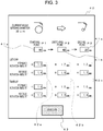
- the inputting and setting are performed by using an input screen 40 of the input setting device 25 shown in Fig. 3 .
- the input screen 40 includes an input box 41a, where a set value of the winding diameter which is set as the starting point P1 is input and set; an input box 41 b, where a set value of the winding diameter which is set as the switching point P2 is input and set, and an input box 41 c, where a set value of the winding diameter which is set as the ending point P3 is input and set.
- the input boxes 41a, 41b, and 41c are provided (displayed) side by side in a horizontal direction.
- the set values of the winding diameters are set in "cm" as shown in Fig. 3 .
- input boxes of the input screen 40 for inputting and setting the set values of the forward rotation amounts and the reverse rotation amounts of the warp beam 2 and the set values of the forward rotation amounts and the reverse rotation amounts of the surface roller 6 are provided (displayed) side by side in a vertical direction below the input boxes 41a, 41b, and 41c for the respective points P1, P2, and P3.
- the forward rotation amounts of the warp beam 2 and the surface roller 6 are fixed values. Therefore, in the illustrated example, an input box for the forward rotation amount of the warp beam 2 and an input box for the forward rotation amount of the surface roller 6 are only provided below the starting point P1; and the set value of the forward rotation amount of the warp beam 2 that has been input and set in the input box for the starting point P1 and the set value of the forward rotation amount of the surface roller 6 that has been input and set in the input box for the starting point P1 are displayed for the switching point P2 and the ending point P3.
- input boxes 42a are provided (displayed) vertically side by side below the input box 41 a for the starting point P1.
- the input boxes 42a are provided for inputting and setting the set value of the forward rotation amount of the warp beam 2 and the set value of the forward rotation amount of the surface roller 6, and the set value of the reverse rotation amount of the warp beam 2 and the set value of the reverse rotation amount of the surface roller 6 for the point in time the winding diameter is the starting point P1.
- Input boxes 42b are provided (displayed) vertically side by side below the input box 41 b for the switching point P2.
- the input boxes 42b are provided for inputting and setting the set value of the reverse rotation amount of the warp beam 2 and the set value of the reverse rotation amount of the surface roller 6 for the point in time the winding diameter is the switching point P2.
- the set value of the forward rotation amount of the warp beam 2 and the set value of the forward rotation amount of the surface roller 6 that have been input and set in the input boxes 42a are also displayed below the input box 41 b for the switching point P2.
- input boxes 42c are provided (displayed) vertically side by side below the input box 41 c for the ending point P3.
- the input boxes 42c are provided for inputting and setting the set value of the reverse rotation amount of the warp beam 2 and the set value of the reverse rotation amount of the surface roller 6 for the point in time the winding diameter is the ending point P3.
- the set value of the forward rotation amount of the warp beam 2 and the set value of the forward rotation amount of the surface roller 6 that have been input and set in the input boxes 42a are also displayed below the input box 41 c for the ending point P3.
- the set values of the forward rotation amounts and the set values of the reverse rotation amounts are in "mm" as shown in Fig. 3 . That is, in the embodiment, the movement amounts of the warp W and the cloth F that are equivalent to the rotation amounts are set for the set values of the forward rotation amounts and the set values of the reverse rotation amounts. More specifically, it is assumed that as the warp beam 2 (the surface roller 6) rotates in the forward direction and the reverse direction, the warp W (the cloth F) on the warp beam 2 (the surface roller 6) moves by amounts corresponding to the rotation amounts. Therefore, in the embodiment, the movement amounts thereof (equivalent to the rotation amounts) are set as substitute values for the forward rotation amounts and the reverse rotation amounts. Incidentally, the movement amounts thereof (equivalent to the rotation amounts in value) match arc lengths determined on the basis of the rotation amounts thereof and the winding diameter of the warp beam 2 (the diameter of the surface roller 6).
- the set values are input and set in the respective input boxes 41 a to 41 c and 42a to 42c.
- An execute button 43 is provided on the input screen 40.
- the execute button 43 is operated (touched) after inputting and setting the set values in the respective input boxes 41 a to 41 c and 42a to 42c as mentioned above, the input and set set values are made valid, and the set values are sent to and stored in the storage unit 26.
- the winding diameter at a point in time the warp beam 2 is fully wound (90 cm in the illustrated example) is set as the starting point P1
- the winding diameter at a point in time the warp W around the warp beam 2 has been completely consumed is set as the ending point P3. That is, in the embodiment, in the set range from when the warp W is fully wound around the warp beam 2 to when the warp W is completely consumed, the kickback control according to the present invention is performed.
- the warp beam 2 is such that the warp W is wound around a barrel thereof (not shown); and the detection of the winding diameter by the winding-diameter detecting device includes the detection of the barrel diameter.
- the detection value provided by the winding-diameter detecting device is equivalent to the barrel diameter instead of being zero. Consequently, when the time of complete consumption is made to correspond to the ending point, the barrel diameter (20 cm in the illustrated example) is set in the input box 41c.
- the switching point P2 is set in order to, at a stoppage time of the loom 1 for the winding diameter in each section above defined by the switching point P2, the kickback amounts (the movement amounts of the cloth fell CF) based on the forward rotation amounts of the warp beam 2 and the surface roller 6 and the reverse rotation amounts of the warp beam 2 and the surface roller 6 determined by the computing expressions are closer to desired kickback amounts corresponding to the actual entire stretching amounts of the warp W. This is described in more detail below.
- the path length of the warp W (more specifically, the path length from a draw-out point of the warp W around the warp beam 2 to the cloth fell CF) changes in the form of a quadratic curve as the weaving progresses.
- the entire stretching amount of the warp W during the stoppage period of the loom 1 is such that the stretching amount per unit length of the warp W is constant, the entire stretching amount corresponds to the path length of the warp W at a point in time. Therefore, the entire stretching amount of the warp W when it is assumed that the stoppage times are the same changes in the form of a quadratic curve with respect to a change in the winding diameter.
- the cloth fell CF is displaced by an amount corresponding to the entire stretching amount, and the kickback operation is performed for correcting the displacement of the cloth fell CF, so that the aforementioned desired kickback amounts are in correspondence with the displacement amounts of the cloth fell CF (the entire stretching amounts) during the stoppage period of the loom.
- the desired kickback amount is a value obtained by adding the movement amount of the cloth fell CF towards the warp let-off side for compensating for the insufficient beating force (hereunder referred to as "compensation movement amount") to the movement amount of the cloth fell CF towards the warp let-off side in correspondence with the aforementioned entire stretching amount.
- the insufficient beating force is caused by the rpm of the main shaft MS at the time the loom 1 is started being less than the rpm during steady-state operation. Therefore, the compensation movement amount is a constant value regardless of the winding diameter and the stoppage time.
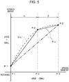
- the desired kickback amount for each point in time for the winding diameter is a value obtained by adding the compensation movement amount, which is constant, to the movement amount of the cloth fell CF corresponding to the entire stretching amount. Since the entire stretching amount changes in the form of a quadratic curve with respect to a change in the winding diameter as mentioned above, similarly to the entire stretching amount, the desired kickback amount changes in the form of a quadratic curve with respect to changes in the winding diameter. With the horizontal axis indicating the winding diameter and the vertical axis indicating the kickback amount, a graph showing the relationship between the winding diameter and the desired kickback amount is as shown by a broken line in Fig. 5 .
- the kickback amount information includes the set values of the forward rotation amounts of the warp beam 2 and the surface roller 6 and the set values of the reverse rotation amounts of the warp beam 2 and the surface roller 6 for the points P1, P2, and P3.
- the set values for the points P1, P2, and P3 are set on the basis of previously determined desired final reverse rotation amounts allowing kickback operation by the desired kickback amounts for the points in time. Therefore, when the kickback amounts for the points P1, P2, and P3 are indicated by dots (black dots) on the graph of Fig. 5 , the points are positioned on the aforementioned broken line.
- the set range information does not include the switching point P2 in the set range from the starting point P1 to the ending point P3
- the kickback amount information does not include the set values of the forward rotation amounts of the warp beam 2 and the surface roller 6 and the set values of the reverse rotation amounts of the warp beam 2 and the surface roller 6 at a point in time (the switching point P2) between the starting point P1 and the ending point P3 and includes instead a computing expression for determining by linear interpolation, such as that described above, the final reverse rotation amount for the point in time for the winding diameter between the starting point P1 and the ending point P3, the relationship between the winding diameter and the kickback amount for each point in time for the winding diameter is as shown by an alternate long and short dash line in the graph of Fig. 5 .
- the difference between the desired kickback amount and the kickback amount when the actual kickback operation is executed is large particularly in
- the set range information includes the switching point P2 and the set values of the forward rotation amounts of the warp beam 2 and the surface roller 6 and the set values of the reverse rotation amounts of the warp beam 2 and the surface roller 6 for the switching point P2
- the relationship between the winding diameter and the kickback amount for each point in time for the winding diameter is as shown by a solid bent line SL in the graph of Fig. 5 .
- the movement amount related information includes, as the set range information, the switching point P2, and, as the kickback amount information, the set values of the forward rotation amounts of the warp beam 2 and the surface roller 6 and the set values of the reverse rotation amounts of the warp beam 2 and the surface roller 6 for the switching point P2.
- the difference between the actual kickback amount and the desired kickback amount in each section is determined in accordance with the winding diameter that is set as the switching point P2.
- the winding diameter is set such that the difference between the two kickback amounts in each section is small.
- the winding diameter that is the switching point P2 for example, trying to graph the relationship between the winding diameter and the kickback amount as shown in Fig. 5 makes it possible to determine desirable values. The method of determining the switching point P2 is described in more detail below.
- the relationship between the winding diameter and the desired kickback amount in the loom 1 that performs weaving is graphed.
- the path lengths for the points in time for the winding diameters (including the winding diameters that are set as the starting point P1 and the ending point P3) for each predetermined interval for the loom 1 are determined.
- the path lengths can be determined on the basis of, for example, the positional relationship between the warp beam 2 and the tension roller 4 (the guide roller 3) of the loom 1.
- the entire stretching amounts corresponding to the path lengths for the points in time for the winding diameters are determined.
- the entire stretching amounts when the loom 1 is stopped change (increase) with the passage of the stoppage time. Accordingly, the entire stretching amounts are determined on the assumption that the loom 1 is stopped at each point in time for the winding diameter and that the stoppage time is a predetermined stoppage time (reference stoppage time). That is, the entire stretching amounts when the loom 1 is stopped for only the reference stoppage time at the points in time for the winding diameters are determined.
- the entire stretching amounts for the points in time for the winding diameters are not determined only on the basis of the path lengths for the points in time for the winding diameters, but differ in accordance with the type of warp W, used in the weaving, and the weaving conditions (such as the set tension of the warp W). In other words, this is because when the type of warp W differs, even if the set tension of the warp W is the same, the entire stretching amounts differ due to differences in the stretching amount per unit length of the warp W; and when the weaving conditions differ (in particular, the set tension of the warp W differs), even if the type of warp W is the same, the entire stretching amounts differ.
- the entire stretching amounts corresponding to the path lengths at the points in time for the winding diameters are determined on the basis of the type of warp W and the set tension of the warp W in addition to the path lengths. More specifically, for example, tests regarding the type of warp W used in the weaving at a certain time are previously conducted, the stretching amount of the warp W when the tension that is the same as the set tension at the time of the weaving is set for a stoppage time that is the same as the reference stoppage time is actually measured, and the stretching amount per unit length of the warp W during the reference stoppage time is determined on the basis of the actually measured stretching amount.
- the entire stretching amount for each point in time for the winding diameter can be determined.
- the stretching rate of the warp W in terms of the relationship between the tension and the time is to be determined on the basis of, for example, the physical properties of the warp W or past data
- the entire stretching amount for each point in time for the winding diameter can be determined by computation on the basis of the path length for each point in time for the winding diameter.
- the desired kickback amount for each point in time for the winding diameter is determined.
- the desired kickback amounts that have been determined as described above with respect to the winding diameters are plotted on a graph in which the horizontal axis indicates the winding diameter and the vertical axis indicates the kickback amount; and the plotted points are smoothly connected by a line.
- a curve DL like the broken line shown in Fig. 5 , that tends to change in the form of a quadratic curve is drawn on the graph.
- the curve DL (the broken line in Fig. 5 ) indicates the relationship between the winding diameter and the desired kickback amount in the set range from the starting point P1 to the ending point P3.
- the curve DL that is drawn in this way and that indicates the relationship between the winding diameter and the desired kickback amount differs depending upon, for example, the path lengths at the points in time for the winding diameters (the structure of the loom 1), the type of warp W used in the weaving, and the set tension of the warp W during the weaving. Since the curve DL indicates the relationship between the winding diameter and the desired kickback amount in the set range of the winding diameter from the starting point P1 to the ending point P3 as mentioned above, the starting point (the left end of the broken line shown in Fig.
- the starting point of the curve DL and the plotted point are connected to each other by a straight line, and the plotted point and the ending point of the curve DL are connected to each other by a straight line, as a result of which a bent line SL (the solid bent line in Fig. 5 ) is drawn.
- the drawn bent line SL is compared with the curve DL, and the difference between the bent line SL and the curve DL is confirmed.
- the winding diameter that is set as the switching point P2 is determined, and the desired kickback amount for the switching point P2 is determined on the basis of this winding diameter (the switching point P2) and the curve DL of the graph shown in Fig. 5 .
- the desired kickback amount for the starting point P1 and the desired kickback amount for the ending point P3 are determined when the curve DL is being drawn as mentioned above.
- the final reverse rotation amounts of the warp beam 2 and the surface roller 6 for the points in time for the winding diameters are determined.
- the relationship of the kickback amount (the movement amount of the cloth fell CF) in the loom 1 with the final reverse rotation amount of the warp beam 2 and the final reverse rotation amount of the surface roller 6 are determined by previously performing tests or on the basis of, for example, past weaving data. On the basis of this previously determined relationship and the desired kickback amounts, determined as described above, for the points in time for the winding diameter, the final reverse rotation amounts of the warp beam 2 and the final reverse rotation amounts of the surface roller 6, which correspond to the desired kickback amounts, for the points in time for the winding diameter are determined.
- the final reverse rotation amount of the warp beam 2 and the final reverse rotation amount of the surface roller 6 are not the same value, that is, they differ. This is because, since the stretching amount of the warp W and the stretching amount of the cloth F differ (that is, the stretching amount of the warp W is larger than that of the cloth F) when the tension of the warp W and the tension of the cloth F are the same, and since the frictional resistance acting upon the warp W is larger than the frictional resistance acting upon the cloth F when the warp beam 2 and the surface roller 6 reversely rotate (that is, when the warp W and the cloth F move), in order to move the position of the cloth fell CF by an amount that is equivalent to the desired kickback amounts without reducing the tension of the warp W and the tension of the cloth F, the values of the final reverse rotation amounts of the warp beam 2 and the values of the final reverse rotation amounts of the surface roller 6 need to differ in value from each other (more specifically, the final reverse rotation amounts of the warp beam 2 need to be greater than the
- the final reverse rotation amount of the warp beam 2 for the starting point P1, that for the switching point P2, and that for the ending point P3 are 0.2 mm, 0.4 mm, and 0.5 mm, respectively; and the final reverse rotation amount of the surface roller 6 for the starting point P1, that for the switching point P2, and that for the ending point P3 are 0.1 mm, 0.3 mm, and 0.4 mm, respectively.
- the forward rotation amounts of the warp beam 2 and the surface roller 6 are determined.
- the forward rotation amounts of the warp beam 2 and the forward rotation amounts of the surface roller 6 are set at forward rotation amounts (movement amounts) that allow the warp W and the cloth F to overcome the frictional resistances acting upon the warp W and the cloth F when the warp beam 2 and the surface roller 6 reversely rotate and to move by movement amounts equivalent to the reverse rotation amounts of the warp beam 2 and the surface roller 6.
- the forward rotation amounts of the warp beam 2 that are set are fixed values that are the same for the starting point P1, the switching point P2, and the ending point P3; and the forward rotation amounts of the surface roller 6 that are set are fixed values that are the same for the starting point P1, the switching point P2, and the ending point P3.
- the frictional resistances differ depending upon, for example, the type of yarn used in the weaving (the weft Y, the warp W) and the weaving conditions (weaving structure, weft density, and set tension of the warp W). Accordingly, the forward rotation amounts that are set are determined considering, for example, the yarn type and the weaving conditions, and on the basis of, for example, previously performed tests or past data.
- the forward rotation amounts that are set for the warp beam 2 and the forward rotation amounts that are set for the surface roller 6 differ from each other.
- the forward rotation amounts of the warp beam 2 are 1.2 mm
- the forward rotation amounts of the surface roller 6 are 1.0 mm.
- the reverse rotation amounts of the warp beam 2 and the reverse rotation amounts of the surface roller 6 are values obtained by adding the forward rotation amounts to the final reverse rotation amounts of the warp beam 2 and the surface roller 6, the reverse rotation amount of the warp beam 2 for the starting point P1, that for the switching point P2, and that for the ending point P3 are 1.4 mm, 1.6 mm, and 1.7, respectively.
- the reverse rotation amount of the surface roller 6 for the starting point P1, that for the switching point P2, and that for the ending point P3 are 1.1 mm, 1.3 mm, and 1.4 mm, respectively.
- the set values of the winding diameters for the starting point P1, the switching point P2, and the ending point P3 included in the set range information of the movement amount related information and determined as described above, and the set values of the forward rotation amounts and the reverse rotation amounts of the warp beam 2 and the surface roller 6 included in the kickback amount information of the movement amount related information are input and set at the input screen 40 of the input setting device 25, and are stored in the storage unit 26 of the main controlling device 24.
- the controlling unit 28 forms the linear interpolation expression and the addition expression in the computing expression for each of the sections ⁇ and ⁇ , and the formed computing expressions are stored in the storage unit 26.
- the linear interpolation expressions are formed on the basis of basic expressions (that is, the aforementioned a ⁇ ⁇ D1 + K1 and b ⁇ ⁇ D2 + K2) for the sections ⁇ and ⁇ that are stored in the storage unit 26, and on the basis of the set values that have been input and set.
- the controlling unit 28 reads out the basic expressions corresponding to the sections ⁇ and ⁇ from the storage unit 26, determines the coefficient a or the coefficient b from each of the set values, assigns required set values, and forms the linear interpolation expressions.
- the addition expressions for determining the reverse rotation amounts of the warp beam 2 are expressions in which the forward rotation amounts are added to the final reverse rotation amounts, and are formed as expressions in which the set values of the forward rotation amounts, which are fixed values that have been set, are assigned.
- the computing expressions that are formed by the controlling unit 28 in this way are sent to the storage unit 26 from the controlling unit 28, and are stored in the storage unit 26.
- the switching point P2 for dividing the set range into the two sections ⁇ and ⁇ is set such that the relationships between the winding diameters and the final reverse rotation amounts based on the linear interpolation expressions for the sections ⁇ and ⁇ , determined on the basis of the switching point P2, approximates to the relationship between the winding diameter and the desired kickback amount (the final reverse rotation amount), the relationship between the winding diameter and the desired kickback amount changing in the form of a quadratic curve.
- the controlling unit 28 compares the magnitude of a detection value Dx of the winding diameter (the winding diameter for a point in time the loom 1 is restarted) of the warp beam 2 detected by the winding-diameter detecting unit 27 of the winding-diameter detecting device and the magnitude of the set value D2 of the winding diameter set as the switching point P2, the detection value Dx being determined depending upon whether the detection value Dx is included in the section ⁇ of the set range of the winding diameter (between the starting point P1 and the switching point P2) or in the section ⁇ of the set range of the winding diameter (between the switching point P2 and the ending point P3).
- the detection value Dx when the detection value Dx is included in the section ⁇ , the detection value Dx > the set value D2, whereas when the detection value Dx is included in the section ⁇ , the detection value Dx ⁇ the set value D2, so that the controlling unit 28 determines whether the detection value Dx is included in the section ⁇ or the section ⁇ .
- the case in which the detection value Dx is equal to the set value D2 that is, the case in which the winding diameter for a point in time the loom 1 is restarted is equal to the winding diameter that has been set as the switching point P2) is described later.
- the controlling unit 28 reads out from the storage unit 26 the linear interpolation expression for determining the final reverse rotation amount of the warp beam 2 and the final reverse rotation amount of the surface roller 6 for the section ⁇ and the addition expression for determining the reverse rotation amount of the warp beam 2 and the reverse rotation amount of the surface roller 6 for the section ⁇ . Then, on the basis of the read out linear interpolation expression, the read out addition expression, and the detection value Dx of the winding diameter, the controlling unit 28 determines the reverse rotation amount of the warp beam 2 and the reverse rotation amount of the surface roller 6.
- the controlling unit 28 reads out from the storage unit 26 the linear interpolation expression for determining the final reverse rotation amount of the warp beam 2 and the final reverse rotation amount of the surface roller 6 for the section ⁇ and the addition expression for determining the reverse rotation amount of the warp beam 2 and the reverse rotation amount of the surface roller 6 for the section ⁇ . Then, on the basis of the read out linear interpolation expression, the read out addition expression, and the detection value Dx of the winding diameter, the controlling unit 28 determines the reverse rotation amount of the warp beam 2 and the reverse rotation amount of the surface roller 6.
- the entire stretching amount of the warp W changes due to the stoppage time of the loom 1 the final reverse rotation amount of the warp beam 2 and the final reverse rotation amount of the surface roller 6, which are determined by using the corresponding linear interpolation expression, are based on the reference stoppage time. Therefore, when the actual stoppage time differs considerably from the reference time, the determined final reverse rotation amounts need to be corrected on the basis of the stoppage time. Consequently, correction coefficients corresponding to the stoppage time for correcting the final reverse rotation amounts are stored in the storage unit 26.
- the controlling unit 28 may read out the correction coefficient corresponding to the measured stoppage time, and multiply the read out correction coefficient to the final reverse rotation amount of the warp beam 2 and the final reverse rotation amount of the surface roller 6, determined by using the corresponding linear interpolation expression as described above, to determine the final reverse rotation amount of the warp beam 2 and the final reverse rotation amount of the surface roller 6 corresponding to the actual stoppage time (t). Therefore, the computing expressions included in the kickback amount information of the movement amount related information also include the computing expression (the correction expression) for multiplying the correction coefficient to the final reverse rotation amounts.
- the correction coefficient is determined with reference to the entire stretching amount for the reference stoppage time. More specifically, with the relationships between the stoppage time and the entire stretching amount for the points in time for the winding diameters being assumed as being the same, when the entire stretching amount during the stopped state of the loom 1 for a certain winding diameter is actually measured with each predetermined time interval, or when the relationship between the time and the stretching amount per unit length is known, the entire stretching amount for each stoppage time (including the reference stoppage time) is determined by, for example, a calculation based on an initial path length for a certain winding diameter (that is, the path length when the elapsed time in the stopped state is 0). Then, a conversion value of the entire stretching amount for each stoppage time when the entire stretching amount for the reference stoppage time is assumed as being 1 is the correction coefficient.
- the correction coefficient may be one in which its value is set for each predetermined time range (values corresponding to the stoppage times included in the same time range are the same). In the embodiment, the correction coefficient is set in correspondence with the time range in which the reference stoppage time serves as a reference.
- the time range is divided into a time range including the reference stoppage time (middle time range), a stoppage time range that is shorter than the middle time range (initial time range), and a stoppage time range that is greater than or equal to the middle time range (final time range), and the correction coefficients are set for these ranges.
- the final reverse rotation amounts determined by using the linear interpolation expressions and set for the reference stoppage time become the final reverse rotation amounts for the actual stoppage time. That is, in this case, since the determined final reverse rotation amounts are not corrected, the correction coefficient corresponding to the reference stoppage time is 1.0. Therefore, the correction coefficient that is set for the aforementioned middle time range is 1.0.
- the correction coefficient that is set for the initial time range is less than 1.0, and the correction coefficient that is set for the final time range is greater than 1.0.
- the reference stoppage time is 10 minutes
- 5 ⁇ stoppage time ⁇ 15 (minutes) is defined as the middle time range (a range in which kickback operation based on the final reverse rotation amounts for a stoppage time that is the same as the reference stoppage time is performed)
- 1.0 is set and stored as the correction coefficient in the storage unit 26, with the correction coefficient corresponding to the stoppage time of 5 ⁇ t ⁇ 15 (minutes).
- the correction coefficient that is a suitable for the case in which the stoppage time is less than 5 minutes is determined as 0.98 on the basis of the relationship, determined as described above, between the entire stretching amounts and the stoppage times, 0.98 is set and stored as the correction coefficient in the storage unit 26 for the initial time range in which the stoppage time is less than 5 minutes, with the correction coefficient corresponding to the stoppage time of t ⁇ 5 (minutes).
- the correction coefficient that is a suitable for the final time range in which the stoppage time is greater than or equal to 15 minutes is determined as 1.02
- 1.02 is set and stored as the correction coefficient in the storage unit 26 for the final time range in which the stoppage time is greater than or equal to 15 minutes, with the correction coefficient corresponding to t ⁇ 15 minutes.
- the actual stoppage time t of the loom 1 may be determined by counting an elapsed time from when the stop signal Sb has been input to the controlling unit 28 as mentioned above to when the start signal Sa is input to the controlling unit 28 by using a timer (not shown) built in the controlling unit 28.
- the controlling unit 28 determines in which time range the actual stoppage time t that has been determined is included, that is, determines whether the actual stoppage time t is included in the initial time range, the middle time range, or the final time range; and determines the correction coefficient.
- the controlling unit 28 multiplies the determined correction coefficient to the final reverse rotation amount of the warp beam 2 and the final reverse rotation amount of the surface roller 6, determined on the basis of the detection value Dx of the winding diameter and the linear interpolation expression, by using the correction expression, to determine the final reverse rotation amounts corresponding to the actual stoppage time t; and determines the reverse rotation amount of the warp beam 2 and the reverse rotation amount of the surface roller 6 by using the determined final reverse rotation amounts and the addition expression.
- the final reverse rotation amount of the warp beam 2 and the final reverse rotation amount of the surface roller 6 are determined by the computing expression.
- the reverse rotation amount of the warp beam 2 and the reverse rotation amount of the surface roller 6 when the winding diameter is equal to the set value D2 are included in the kickback amount information of the movement amount related information. Therefore, when the determination method is the same, the reverse rotation amounts are determined by using the computing expression as mentioned above. However, instead, when it is determined that the detection value Dx is equal to the set value D2, the reverse rotation amounts included in the kickback amount information that is stored in the storage unit 26 may be read out from the storage unit 26, and the read out reverse rotation amounts may be used.
- the final reverse rotation amounts are determined by using the linear interpolation expression for the section ⁇ , and the reverse rotation amount of the warp beam 2 and the reverse rotation amount of the surface roller 6 are determined on the basis of the final reverse rotation amounts.
- the reverse rotation amounts may be read out from the storage unit 26 and used.
- the controlling unit 28 sends to the let-off controlling device 20 the reverse rotation amount of the warp beam 2 that has been determined as described above and the forward rotation amount of the warp beam 2 that has been read out from the storage unit 26 and that is set as a fixed value; and sends to the take-up controlling device 21 the determined reverse rotation amount of the surface roller 6 and the forward rotation amount of the surface roller 6 that has been read out from the storage unit 26 and that is set as a fixed value.
- the let-off controlling device 20 and the take-up controlling device 21 control the driving of the let-off motor M3 and the driving of the take-up motor M2, respectively, on the basis of the forward rotation amount and the reverse rotation amount of the warp beam 2 and the forward rotation amount and the reverse rotation amount of the surface roller 6, which have been sent from the controlling unit 28, so that the warp beam 2 and the surface roller 6, which are the cloth-fell displacing members, are rotationally driven to perform the kickback operation.
- the cloth fell CF is moved to the warp let-off side position corresponding to the detection value Dx of the winding diameter, and the operation of the loom 1 is started in this state.
- the warp beam 2 and the surface roller 6, which are the cloth-fell displacing members are such that the forward rotation amount and the reverse rotation amount of the warp beam 2 and the forward rotation amount and the reverse rotation amount of the surface roller 6 are determined at the controlling unit 28 of the main controlling device 24, and such that the driving of the warp beam 2 and the driving of the surface roller 6 are controlled at the let-off controlling device 20 and the take-up controlling device 21, respectively. Therefore, in the embodiment, the controlling unit 28 of the main controlling device 24, the let-off controlling device 20, and the take-up controlling device 21 correspond to driving controlling devices of the weaving bar preventing apparatus according to the present invention.
- the driving amounts (the forward rotation amounts and the reverse rotation amounts) thereof for the kickback operation that is performed for a point in time the loom is restarted are in correspondence with the winding diameter (the entire stretching amount of the warp W) for the point in time the loom is restarted. Therefore, the kickback amount of the kickback operation is close to the desired kickback amount, so that it is possible to more effectively prevent a weaving bar (stop bar) from occurring.
- the winding-diameter detecting device for determining the winding diameter of the warp W wound around the warp beam 2 a structure that uses the non-contact distance sensor 10 is used.
- the winding-diameter detecting device of the weaving bar preventing apparatus according to the present invention is not limited to the device having such a structure, and, thus, may be any publicly known winding-diameter detecting device.
- the winding-diameter detecting device may be a device that uses a member that contacts a surface of the warp W, wound around the warp beam 2, and whose contact state is maintained, to determine the winding diameter by detecting, by using a sensor or the like, the position of the member that changes as the winding diameter changes (is reduced).
- the winding-diameter detecting device is not limited to a device, such as that mentioned above, that is formed so as to directly determine the winding diameter by using the sensor, and, thus, may be a device that is formed so as to indirectly determine the winding diameter by computation based on the rotation amount of the let-off motor M3 or the rotation amount of the warp beam 2 per unit time during the weaving.
- the present invention is not limited to the embodiment and examples described above, and may be modified as appropriate within a range that does not depart from the gist of the present invention.
Landscapes
- Engineering & Computer Science (AREA)
- Textile Engineering (AREA)
- Looms (AREA)
Abstract
Description
- The present invention relates to a weaving bar preventing method in which, when a loom is started, a cloth fell of a cloth is moved towards a warp let-off side, and to an apparatus for the same.
- When a loom is stopped due to, for example, improper weft insertion, during the time in which the loom is stopped, gradual stretching of the warp occurring as time passes due to the influence of tension, self-weight, etc., of the warp causes a cloth fell to moves gradually towards a cloth take-up side. When weaving is started (restarted) in the state in which the cloth fell has moved is this way, a weaving bar (a so-called stop bar) occurs in the cloth. Hitherto, for the purpose of preventing the occurrence of such weaving bar (stop bar), prior to starting the weaving, the cloth fell is moved towards the warp let-off side to correct the position of the cloth fell, so that the aforementioned weaving bar is prevented from occurring. The movement (correction) of the position of the cloth fell is performed by driving cloth-fell displacing members that contribute to moving of the cloth fell (such as a warp beam that lets off a warp and a surface roller upon which a woven cloth is wound) in the loom.
- Regarding the correction of the position of the cloth fell, as long as only the stretching of a warp, such as that described above, is considered, the cloth fell only needs to be returned to its normal position (a position that is set as the position thereof when beating is performed during weaving). However, since, in the loom, beating force for beating with a reed is in an insufficient state just before starting the weaving (starting the loom), the insufficient beating force may also cause the aforementioned weaving bar to occur. Therefore, in correcting the position of the cloth fell prior to starting the weaving as mentioned above, the cloth fell may be moved closer to the warp let-off side than the normal position of the cloth fell is in consideration of the insufficient beating force. Incidentally, the operation of correcting the position of the cloth fell prior to starting the weaving in consideration of the stretching of a warp or insufficient beating force, such as those mentioned above, is also called a "kickback operation". Control of a loom for executing the kick-back operation is also called "kickback control".
- A related art regarding such kickback control is disclosed in, for example,
Japanese Unexamined Patent Application Publication No. 61-083355 PTL 1 presupposes kickback control that is performed for compensating for the insufficient beating force described above. In addition,PTL 1 discloses changing the kickback amount of the kickback operation (the movement amount of the cloth fell) in proportion to a stoppage time of a loom, that is, changing the kickback amount in correspondence with the stretching of a warp during a stoppage period of the loom. Further,PTL 1 discloses changing the amount of rotation of a let-off motor in inverse proportion to the winding diameter of a warp wound around a warp beam, and performing control such that the kickback amount becomes a preset amount regardless of the winding diameter of the warp beam. - In a loom, since, as weaving progresses, the winding diameter of the warp wound around the warp beam gradually becomes smaller, the distance from a draw-out point of the warp that is wound around the warp beam to a tension roller upon which the drawn-out warp is wound becomes large, as a result of which a warp path length from the draw-out point to the cloth fell becomes large. In other words, in the loom, as the winding diameter changes as the weaving progresses, the path length changes. The larger the winding diameter, the smaller the path length; whereas, the smaller the winding diameter, the larger the path length.
- Regarding the stretching of the warp during the stoppage period of the loom mentioned above, in the case where the stoppage times are the same, when the stretching amount per unit length of the warp is constant, the stretching amount of the entire warp from the warp beam to the cloth fell (the entire stretching amount) becomes large as the path length becomes larger. Therefore, the entire stretching amount becomes smaller as the winding diameter becomes larger, and becomes larger as the winding diameter becomes smaller.
- The movement of the cloth fell towards the take-up side during the stoppage period of the loom mentioned above is caused by the stretching of the warp during the stoppage period. The movement amount is in correspondence with the entire stretching amount. Therefore, even if the stoppage times are the same, the movement amount of the cloth fell when an initial winding diameter prior to starting the weaving is large and the movement amount of the cloth fell when the winding diameter is reduced due to the progression of the weaving differ from each other (that is, the movement amount becomes larger as the winding diameter becomes smaller).
- However, the related art above only considers making the kickback amount constant in the kickback operation. Therefore, in the related art, due to differences in the movement amount of the cloth fell caused by the winding diameter, the set kickback amount and the actual movement amount of the cloth fell may not correspond to each other depending upon the winding diameter. Consequently, in the entire weaving period, a weaving bar (stop bar) that occurs due to the stoppage of the loom cannot be effectively prevented from occurring.
- Accordingly, it is an object of the present invention to provide a weaving block preventing method that is provided for a loom and that is capable of effectively preventing the occurrence of a weaving bar (stop bar) caused by the stoppage of the loom, and an apparatus therefor.
- To this end, according to an aspect of the present invention, there is provided a weaving bar preventing method in which, when a loom is started, a cloth-fell displacing member that contributes to moving of a cloth fell of a cloth is driven to move the cloth fell towards a warp let-off side. The method includes previously storing movement amount related information in the loom, the movement amount related information being information for determining a movement amount of the cloth fell, the movement amount related information being determined such that, in a set range that has been preset and that is related to a winding diameter of a warp wound around a warp beam, the smaller the winding diameter, the larger the movement amount; and when the winding diameter for a point in time the loom is started is included in the set range, the cloth-fell displacing member is driven on the basis of the winding diameter for the point in time and the movement amount related information.
- According to another aspect of the present invention, there is provided a weaving bar preventing apparatus which, when a loom is started, causes a cloth-fell displacing member that contributes to moving of a cloth fell of a cloth to be driven to move the cloth fell towards a warp let-off side. The weaving bar preventing apparatus includes a winding-diameter detecting device that determines a winding diameter of a warp wound around a warp beam; a storage unit that stores movement amount related information that is information for determining a movement amount of the cloth fell, the movement amount related information being determined such that, in a set range that has been preset and that is related to the winding diameter, the smaller the winding diameter, the larger the movement amount; and a driving controlling device that controls driving of the cloth-fell displacing member, the driving controlling device controlling the driving of the cloth-fell displacing member on the basis of the winding diameter for a point in time the loom is started and the movement amount related information stored in the storage unit when the winding diameter for the point in time the loom is started is included in the set range, the winding diameter for the point in time the loom is started having been determined by the winding-diameter detecting device.
- Here, the term "cloth-fell displacing member (that contributes to moving of the cloth fell)" refers to a member that can move the cloth fell and that is provided so as to be driven in a cloth fell movement direction by driving means, such as a motor. Examples thereof correspond to a warp beam that lets off a warp that is provided continuously with the cloth fell, and a surface roller upon which a cloth that is provided continuously with the cloth fell is wound. In addition, the tension roller upon which the warp is wound between the warp beam and the cloth fell may also be included as a cloth-fell displacing member. However, the cloth-fell displacing member for the present invention corresponds to at least one of these examples. "Driving controlling devices" also include a controlling device that controls the driving of the driving means.
- "Movement amount related information" refers to information for determining the movement amount of the cloth fell towards the warp let-off side in the set range of the winding diameter; and corresponds to, for example, database in which the winding diameter and the movement amount corresponding to the winding diameter are associated with each other, and a computing expression in which the winding diameter is a variable and that is used to determine the movement amount corresponding to the winding diameter by substituting the winding diameter. However, the movement amount related information is not limited to information that is determined for determining the movement amount itself on the basis of the winding diameter. The movement amount related information may be information that is determined for determining the driving amount of the cloth-fell displacing member to determine the movement amount, or information that is determined for determining the driving amount of the driving means (such as a motor) that drives the cloth-fell displacing member. The movement amount related information is information that is determined such that the movement amount and the driving amount that are determined become larger as the winding diameter becomes smaller.
- In the present invention described above, the movement amount related information may be information that is determined such that a change in the movement amount with respect to a change in the winding diameter in a first-half portion range and a change in the movement amount with respect to a change in the winding diameter in a second-half portion range differ from each other, the first-half portion range being from a starting point of the set range to an intermediate portion of the set range, the second-half portion range being from the intermediate portion to an ending point of the set range.
- Further, the movement amount related information may be determined such that a proportion of an increased portion of the movement amount for the point in time the loom is started with respect to a decreased amount of the winding diameter for the point in time the loom is started with reference to the starting point of the set range differs at each point in time the loom is started in the set range. Alternatively, the movement amount related information may include one or more boundary values that divide the set range into two or more sections as a result of setting the one or more boundary values in the set range of the winding diameter, and a rate of change in the movement amount with respect to a change in the winding diameter in each section that is defined by the one or more boundary values is constant and the rate differs for each section.
- According to the present invention, in the kickback operation that is performed when the loom is started, the kickback amount (the movement amount of the cloth fell) is changed in accordance with the movement amount related information so as to become larger as the winding diameter becomes smaller at a point in time the loom is started. Therefore, the winding diameters naturally differ at corresponding points in time of stoppage of the loom during the weaving period. Consequently, even if the stoppage times are the same, the stretching amounts of the warp differ from each other (the movement amounts of the cloth fell differ during the stoppage periods), so that it is possible to effectively prevent the occurrence of a weaving bar (stop bar) caused by stopping the loom in each state.
- The kickback operation is performed at a point in time the loom is started (when a weaving operation is started) after stopping the loom (more precisely, is performed just before starting the loom). In the present invention, the driving of the cloth-fell displacing member is controlled on the basis of the winding diameter for a point in time the loom is started. However, the winding diameter almost never changes from the point in time the loom is stopped to when the loom is started. Therefore, "the winding diameter for a point in time the loom is started" according to the present invention is not only limited to that determined by computation and detection at a point in time the loom is started; and may be one determined at any point in time during the stoppage of the loom before starting the loom. Depending upon the loom, the winding diameter is successively determined during the weaving operation for, for example, performing control, and the winding diameter that is finally determined during the weaving operation before stopping the loom can be used as the winding diameter for a point in time the loom is started.
- It is possible to more effectively prevent the occurrence of a weaving bar (stop bar) when the movement amount related information for determining the kickback amount at each point in time the loom is started is determined such that a change in the movement amount with respect to a change in the winding diameter in the first-half portion range of the set range and a change in the movement amount with respect to a change in the winding diameter in the second-half portion range of the set range differ from each other.
- More specifically, in general, the path length tends to become successively larger as the winding diameter changes as mentioned above. Therefore, in the present invention described above, even if the movement amount related information is determined such that the relationship between the movement amount and the winding diameter in the set range is one in which the movement amount changes at a fixed rate with respect to a change in the winding diameter (that is, the change in the movement amount with respect to a change in the winding diameter in the set range tend to be linear), the occurrence of a weaving bar (stop bar) is more effectively prevented than in the above-described related art.
- However, more specifically, the path length does not change by fixed amounts with respect to predetermined winding diameter changes. Instead, the amount of change of the path length tends to change successively in one direction as the winding diameter changes. Therefore, when the set range is divided into the first-half portion range and the second-half portion range, the amount of change in the path length with respect to a change in the winding diameter in the first-half portion range and the amount of change in the path length with respect to a change in the winding diameter in the second-half portion range differ from each other. Therefore, by determining the movement amount related information such that the amount of change in the movement amount with respect to a change in the winding diameter in the first-half portion range and the amount of change in the movement amount with respect to a change in the winding diameter in the second-half portion range differ from each other, it is possible to cause the movement amount that is determined on the basis of the movement amount related information to be closer in value to the actual entire stretching amount at each point in time the loom is started. As a result, compared to when the movement amount related information is set such that the rate of change in the movement amount with respect to a change in the winding diameter is fixed in the set range, the occurrence of a weaving bar (stop bar) can be more effectively prevented.
- As mentioned above, the path length is such that its amount of change with respect to predetermined winding diameter changes tends to change successively in one direction as the winding diameter changes. That is, the path length changes in the form of a quadratic curve as the winding diameter changes. Therefore, by determining the movement amount related information such that the proportions of increased amounts of the movement amount with respect to decreased amounts of the winding diameter with reference to a starting point of the set range differ from each other for corresponding points in time the loom is started in the set range (that is, such that the movement amount with respect to the winding diameter changes in the form of a quadratic curve as the winding diameter changes), the occurrence of a weaving bar (stop bar) can be more effectively prevented.
- Determining the movement amount related information such that the movement amount changes in the form of a quadratic curve as the winding diameter changes so as to match the tendency with which the path length (the entire stretching amount) changes is most effective in terms of preventing the occurrence of a weaving bar (stop bar). However, when an attempt is made to determine the movement amount related information such that such changes in the movement amount are indicated, the content of the movement amount related information, itself, becomes complicated. Moreover, since the tendency with which the path length (the entire stretching amount) changes depend upon the warp type, weaving conditions, etc., it is necessary to set the movement amount related information in accordance therewith (combinations thereof), as a result of which the movement amount related information becomes very troublesome to set.
- On the other hand, if the movement amount related information is determined such that the rate of change in the movement amount with respect to a change in the winding diameter is fixed, that is, if, as mentioned above, the movement amount is increased with a tendency to increase linearly, the setting of the movement amount related information can be facilitated. Therefore, the movement information related information is determined such that the information includes one or more of the boundary values that divide the set range into two or more sections, the set range is divided into two or more sections for any winding diameters, the movement amount changes with a tendency to change linearly (fixed rate) as mentioned above in each section, and the rate of change differs in each section. By this, the change in the movement amount in accordance with this movement amount related information can be made to approximate to changes in the form of a quadratic curve above while the change in the movement amount tends to be linear. This makes it possible to effectively prevent the occurrence of a weaving bar (stop bar) while facilitating the setting of the movement amount related information.
-
-
Fig. 1 is a an explanatory view of an exemplary loom to which the present invention is applied; -
Fig. 2 is a block diagram of an exemplary weaving bar preventing apparatus according to the present invention; -
Fig. 3 is an explanatory view of an exemplary input screen for inputting and setting movement amount related information according to the present invention; -
Fig. 4 is an explanatory view of an example according to the present invention; -
Fig. 5 is an explanatory view of an example according to the present invention; -
Figs. 6A and 6B are explanatory views of other examples according to the present invention; -
Figs. 7A and 7B are explanatory views of still other examples according to the present invention; and -
Figs. 8A and 8B are explanatory views of still other examples according to the present invention. - A weaving bar preventing apparatus of a loom according to an embodiment of the present invention is hereunder described with reference to the drawings.
-
Fig. 1 illustrates an exemplary loom (such as an air jet loom) to which the weaving bar preventing apparatus according to the present invention is applied. In aloom 1, a warp W that has been let off in the form of a sheet from awarp beam 2 is wound upon and guided by aguide roller 3 and atension roller 4, after which the warp W is guided to a cloth fell CF via healds H and a reed R. The warp W is subjected to a shedding motion by upward and downward movements of the corresponding healds H to form a shed in a predetermined period during one weaving cycle. Then, a weft insertion device (not shown) inserts a weft Y into the shed formed by the warp W, and the reed R beats the weft Y against the cloth fell CF, so that a cloth F is woven. The cloth F woven in this way is wound upon and guided by aguide roller 5 from the cloth fell CF, and then is taken up by a take-uproller 8 via a surface roller 6 and two niprollers - The woven cloth F is in a state in which it is nipped by the surface roller 6 and the two nip
rollers rollers 7 are rotated by the rotation of the surface roller 6. Accordingly, during weaving, the surface roller 6 is rotationally driven on the basis of a preset weft density and a preset rpm of a main shaft MS. By this, the cloth F is pulled towards the take-uproller 8. During the weaving, as the cloth F is pulled by, for example, the surface roller 6 as mentioned above, the warp W that is formed continuously with the cloth F at the cloth fell CF is also pulled. Therefore, by controlling rotational driving of thewarp beam 2 that lets off the warp W, the tension of the warp W is controlled so as to be maintained at a predetermined target tension. In this way, in theloom 1, by rotationally driving the surface roller 6 and thewarp beam 2, and controlling the driving thereof, the weaving is performed while the cloth fell CF is successively moved. - The
warp beam 2 is rotationally driven by a let-off motor M3. The surface roller 6 is rotationally driven by a take-up motor M2. Incidentally, the healds H are driven in an up-down direction by ashedding driving device 22 in which the main shaft MS (or a dedicated driving motor) of theloom 1 is a driving source, and the reed R is subjected to swing (beating) driving in a front-back direction by areed driving device 23 in which the main shaft MS is a driving source. The main shaft MS is rotationally driven by a main shaft motor M1. -
Fig. 2 shows a loom controllingapparatus 30 that is provided for theloom 1 and that, for example, controls the driving of each of the aforementioned motors. The loom controllingapparatus 30 includes amain controlling device 24, a let-off controllingdevice 20 that controls the driving of the let-off motor M3, and a take-up controllingdevice 21 that controls the driving of the take-up motor M2. Themain controlling device 24 includes a controllingunit 28 that controls the driving of the main shaft motor M1 and astorage unit 26 that is connected to the controllingunit 28. The let-off controllingdevice 20 and the take-up controllingdevice 21 are each connected to the controllingunit 28 and thestorage unit 26 of themain controlling device 24. - The loom 1 also includes a winding-diameter detecting device for detecting the winding angle of the warp W wound around the
warp beam 2. The winding-diameter detecting device includes adistance sensor 10 that is provided near thewarp beam 2 so as to oppose a surface of the sheet-like warp W wound around thewarp beam 2 as shown inFig. 1 , and a winding-diameter detecting unit 27 that determines the winding diameter on the basis of a signal from thedistance sensor 10. Thedistance sensor 10 detects the distance to the warp W around thewarp beam 2, and outputs a distance signal corresponding to the detected distance to the winding-diameter detecting unit 27. The winding-diameter detecting unit 27 is included in the loom controllingapparatus 30, is connected to the let-off controllingdevice 20 and the controllingunit 28 of themain controlling device 24, and outputs the determined winding diameter to the let-off controllingdevice 20 and the controllingunit 28. - An
input setting device 25 of theloom 1 is connected to thestorage unit 26 of themain controlling device 24. Theinput setting device 25 includes, for example, a touch-panel display screen, and allows inputting and setting of weaving conditions, such as various setting values and conditions, on, for example, a set screen of the display screen. The weaving conditions that have been input and set at theinput setting device 25 are sent to thestorage unit 26 of themain controlling device 24 and stored in thestorage unit 26. Incidentally, the weaving conditions that are input and set at theinput setting device 25 and stored in thestorage unit 26 include, for example, set values of weft density, set values of rpm (rotation speed) of the main shaft MS, and target set values of the tension of the warp W. - During the weaving, the controlling
unit 28 of themain controlling device 24 drives the main shaft motor M1 in accordance with the set values of rpm of the main shaft MS that have been input and set at theinput setting device 25 and stored in thestorage unit 26 of themain controlling device 24 as mentioned above. An encoder EN that detects the rotation amount of the main shaft motor M1 is connected to the main shaft motor M1. A rotation amount signal S corresponding to the rotation amount of the main shaft motor M1 is output (fed back) to the controllingunit 28 from the encoder EN. The driving of the main shaft motor M1 is controlled on the basis of the set values of rpm and the rotational amount signal S from the encoder EN. This causes the main shaft MS to be rotationally driven with the rpm corresponding to the rpm of the main shaft motor M1. - Incidentally, since the rpm of the main shaft motor M1 and the rpm of the main shaft MS correspond with each other with a predetermined proportion, the controlling
unit 28 can determine and obtain the rpm of the main shaft MS on the basis of the rotation amount signal S from the encoder EN. Therefore, the controllingunit 28 determines the rpm (rotation speed) of the main shaft MS on the basis of the rotation amount signal S, and sends the determined rpm of the main shaft MS to the take-up controllingdevice 21 and the let-off controllingdevice 20. - The take-up controlling
device 21 determines a basic speed regarding the take-up of the cloth F on the basis of the set values of weft density and the rpm of the main shaft MS determined by the controllingunit 28, the set values of the weft density and the rpm of the main shaft MS being stored in thestorage unit 26 of themain controlling device 24, and controls the driving of the take-up motor M2 so as to drive the take-up motor M2 in accordance with the basic speed. By this, during the weaving, the surface roller 6 is rotationally driven by the take-up motor M2 such that the cloth F is pulled at a speed corresponding to the set weft density. - The let-off controlling
device 20 determines a basic speed regarding the let-off of the warp W on the basis of the set values of weft density and the rpm (rotation speeds) of the main shaft MS, which are stored in thestorage unit 26 of themain controlling device 24; and corrects the basic speed on the basis of the winding diameter of thewarp beam 2 determined by the windingdiameter detecting unit 27, and controls the driving of the let-off motor M3 so as to drive the let-off motor M3 in accordance with the corrected basic speed. - However, as mentioned above, the let-off controlling
device 20 controls the driving of the let-off motor M3 such that the tension of the warp W is maintained at a predetermined target tension. For realizing this purpose, theloom 1 includes a tension detector 9 that is connected to thetension roller 4, upon which the warp W is wound, and that detects the tension of the warp W. Thestorage unit 26 of themain controlling device 24 stores target values of the tension of the warp W (target tension values). The let-off controllingdevice 20 compares the target tension values of the warp W stored in thestorage unit 26 and a detection tension value of the warp W detected by the tension detector 9, and further corrects the basic speed related to the let-off if necessary. By this, during a weaving operation, thewarp beam 2 is rotationally driven by the let-off motor M3 such that the warp W is let off in a state in which its target tension value is maintained. - In the loom 1 described above, when something causes the loom 1 to stop or an operator operates an operation stop button (not shown), a stop signal Sb is input to the controlling
unit 28, and theloom 1 is stopped. When the cause of the stoppage of theloom 1 is eliminated, or when the operator operates an operation button (not shown), a start signal Sa is input to the controllingunit 28. When the start signal Sa is input to the controllingunit 28, in order to prevent the occurrence of a weaving bar (the so-called stop bar) caused by the stretching of the warp W during the stoppage period mentioned above, the following is performed. That is, when theloom 1 is started after stopping the loom 1 (just before starting the loom 1), the so-called kickback operation that causes the loom 1 to operate such that the position of the cloth fell CF is moved towards the warp let-off side while the main shaft MS is stopped is executed. The movement amount (kickback amount) of the cloth fell CF in the kickback operation is determined in consideration of insufficient beating force just after the start of the loom in addition to the stretching of the warp W as mentioned above. - Then, according to the present invention, in order to perform kickback control in the
loom 1 to execute the kickback operation, with movement amount related information, which is information for determining the kickback amount (the movement amount of the cloth fell CF) including the winding diameter as a variable, being pre-stored in the loom, when performing the kickback control, the cloth-fell displacing member that contributes to the moving of the cloth fell CF is driven on the basis of the winding diameter for a point in time the loom is started and the movement amount related information thereof. The movement amount related information is information that is determined such that, in a set range that has been preset and that is related to the winding diameter, the smaller the winding diameter, the larger the kickback amount (the movement amount of the cloth fell CF). - Regarding the kickback amount (the movement amount of the cloth fell CF), as mentioned above, since the entire stretching amount of the warp W becomes larger as the winding diameter becomes smaller with respect to a change in the winding diameter, when a starting point and an ending point of the set range of the winding diameter are P1 and P3, respectively, the entire stretching amount at the ending point P3 is larger than the entire stretching amount at the starting point P1. In addition, in the present invention, the kickback amount (the movement amount of the cloth fell CF) at the starting point P1 and the kickback amount (the movement amount of the cloth fell CF) at the ending point P3 are previously determined in accordance with the entire stretching amounts. That is, the kickback amounts (the movement amounts of the cloth fell CF) are previously determined such that the movement amount at the ending point P3, where the winding diameter is smaller than that at the starting point P1, is larger than the movement amount at the starting point P1.
- In the embodiment, the kickback operation is performed by rotationally driving the
warp beam 2 and the surface roller 6. Therefore, in the embodiment, when performing the kickback operation, thewarp beam 2 and the surface roller 6 function as cloth-fell displacing members of the weaving bar preventing apparatus according to the present invention. - Regarding the rotational driving of the
warp beam 2 and the surface roller 6 when performing the kickback operation, in the embodiment, thewarp beam 2 and the surface roller 6 are rotationally driven such that, after the cloth fell CF has been temporarily moved closer to the warp let-off side than a target position corresponding to the winding diameter for this point in time (hereunder simply referred to as the "target position"), the cloth fell CF is moved towards the cloth take-up side and is positioned at the target position. Therefore, when performing the kickback operation, after thewarp beam 2 has been reversely rotationally driven in a take-up direction of the warp W, thewarp beam 2 is forwardly rotationally driven in a let-off direction of the warp W; and, after the surface roller 6 has been reversely rotationally driven in a returning direction in which the cloth fell F returns towards the cloth-fell-CF side, the surface roller 6 is forwardly rotationally driven in a direction in which the cloth fell F is pulled, in response to the rotation of thewarp beam 2. As a result of reversely rotationally driving and forwardly rotationally driving thewarp beam 2 and the surface roller 6, the cloth fell CF is brought into a state in which it has moved by the movement amount of the cloth fell CF to the target position (kickback amount). - Incidentally, as mentioned above, the kickback operation, in which, after the cloth fell CF has been moved by a large amount so as to be closer to the warp let-off side than the target position is, the cloth fell CF is returned towards the target position (towards the cloth take-up side), is carried out for more reliably moving the cloth fell CF to the target position.
- More specifically, when an attempt is made to move the cloth fell CF towards the target position by only reverse rotations, frictional resistance between the cloth F and, for example, the
guide roller 5, and frictional resistance between the warp W and thetension roller 4, theguide roller 3, and members in which the warp W is inserted (such as the reed R and the healds H) cause the displacement amount of the warp W and the displacement amount of the cloth F resulting from the reverse rotations thereof to be absorbed by changes in tension of the warp W and changes in the tension of the cloth F. Therefore, the cloth fell CF may not move in correspondence with the reverse rotation amounts. Accordingly, the warp W and the cloth F are temporarily moved by a large amount towards the warp let-off side so as to overcome the frictional resistances, and, then, the warp W and the cloth F are moved in the returning direction (towards the cloth take-up side) such that the cloth fell CF is positioned at the target position, so that the cloth fell CF is brought into a state in which it has moved to the target position. - Regarding the reverse rotation amount and the forward rotation amount of the
warp beam 2 and the reverse rotation amount and the forward rotation amount of the surface roller 6 when performing the kickback operation described above, the reverse amounts are naturally larger than the forward rotation amounts. The final reverse rotation amounts of thewarp beam 2 and the surface roller 6, each obtained by subtracting the forward rotation amount from the reverse rotation amount, are equivalent to the reverse rotation amounts in the case where the cloth fell CF is moved to the target position by only reverse rotation when it is assumed that frictional resistances do not exist. The kickback amounts correspond to the final reverse rotation amounts. - Regarding the reverse rotation amounts (the reverse rotation amounts for moving the warp W and the cloth F by a large amount towards the warp let-off side as mentioned above), the frictional resistances are assumed as being substantially constant regardless of the winding diameter. Accordingly, in the embodiment, the reverse rotation amounts are each assumed as being a rotation amount obtained by adding a predetermined reverse rotation amount to the final reverse rotation amount corresponding to the winding diameter. Therefore, the forward rotation amounts are each a forward rotation amount corresponding to the predetermined reverse rotation amount thereof (that is, a rotation amount in the forward rotation direction, which is equivalent to the predetermined reverse rotation amount). That is, in the embodiment, each forward rotation amount is set as a fixed value.
- Strictly speaking, the frictional resistances change because the winding angle of the warp W with respect to the
guide roller 3 changes due to a change in the winding diameter. However, the changes in the frictional resistances are very small. Therefore, in the embodiment, the changes in the frictional resistances caused by changes in the winding diameter are negligible, and are assumed as being constant regardless of the winding diameter. Incidentally, the relationship between the winding angle of the warp W with respect to theguide roller 3 and the winding diameter differ due to, for example, the relationship between the position of theguide roller 3 and thewarp beam 2 in theloom 1. - In the foregoing description, the reverse rotation amounts are described as being large considering that the cloth fell CF does not move by an amount corresponding to the reverse rotation amounts. Since the forward rotations are performed in a state in which the tension of the warp W and the tension of the cloth F are high due to the large amounts of reverse rotations, the forward rotations are not easily affected by the frictional resistances. Consequently, there is no problem even if the forward rotation amounts correspond to a returning movement amount of the cloth fell CF that has moved by an amount corresponding to the reverse rotation amounts to the target position.
- Since the movement amount related information is information that is set for kickback control with respect to the kickback operation described above with respect to the winding diameter in the set range, the movement amount related information also includes information regarding the set range (hereunder referred to as the "set range information"). In addition, in the embodiment, the set range information includes the set values of the winding diameter, which become the starting point P1 and the ending point P3 of the set range. Further, in the embodiment, by setting one boundary in the set range, the set range is divided into two sections. Therefore, the set range information includes the set value of the winding diameter, which is a switching point P2 serving as a boundary value that is set in the set range.
- Further, the movement amount related information includes information regarding the kickback amount (the movement amount of the cloth fell CF) for kickback control performed on the kickback operation described above. (The information regarding the kickback amount is hereunder referred to as the "kickback amount information".) The kickback amount information includes the set values of the reverse rotation amounts of the
warp beam 2 when performing the kickback operation described above and the set values of the reverse rotation amounts of the surface roller 6 when performing the kickback operation described above, in correspondence with the starting point P1, the switching point P2, and the ending point P3. In addition, in the embodiment, reverse rotation amounts of thewarp beam 2 and reverse rotation amounts of the surface roller 6 between the points P1, P2, and P3 of the set range are determined by computing expressions based on the set values for the corresponding points P1, P2, and P3. Therefore, in the embodiment, the kickback amount information included in the movement amount related information also includes the computing expressions. - In the embodiment, the computing expressions each include a linear interpolation expression for linear interpolation between the starting point and the ending point of the corresponding section (P1-P2, P2-P3). Therefore, two of the linear interpolation expressions for the corresponding sections are set with respect to the set range from the starting point P1 to the ending point P3 including the sections described above. Each linear interpolation expression is an expression for determining the final reverse rotation amount. More specifically, each computing expression is as follows. However, in the description below, regarding the two sections, the section from the starting point P1 to the switching point P2 is a section α, and the section from the switching point P2 to the ending point P3 is a section β.
- The linear interpolation expression corresponding to the section α is an expression (a × ΔD1 + K1), which corresponds to coefficient (a) × decreased amount (ΔD1) of the winding diameter from the starting point P1 of this section + final reverse rotation amount (K1) for the starting point P1. The coefficient (a) is determined on the basis of the winding diameters that are set as the starting point P1 and the switching point P2 and on the basis of the final reverse rotation amounts for the corresponding points P1 and P2, determined on the basis of the set values of the reverse rotation amounts of the
warp beam 2 and the surface roller 6 that are set for the corresponding points P1 and P2. The decreased amount (ΔD1) is a variable. Similarly, the linear interpolation expression corresponding to the section β is an expression (b × ΔD2 + K2), which corresponds to coefficient (b) × decreased amount (ΔD2) of the winding diameter from the starting point P2 of this section + final reverse rotation amount (K2) for the starting point P2. The coefficient (b) is determined on the basis of the winding diameters that are set as the switching point P2 and the ending point P3 and the final reverse rotation amounts for the corresponding points P2 and P3, determined on the basis of the set values of the reverse rotation amounts of thewarp beam 2 and the surface roller 6 that are set for the corresponding points P2 and P3. The decreased amount (ΔD2) is a variable. - In addition, since the forward rotation amounts are fixed values as mentioned above, each reverse rotation amount is determined by adding the forward rotation amount, which is a fixed value, to the final reverse rotation amount, determined by the corresponding linear interpolation expression. Therefore, each computing expression included in the kickback amount information includes the expression for this addition (addition expression).
- As mentioned above, the final reverse rotation amount (Kx) for the winding diameter (Dx) at a point in time other than the points P1, P2, and P3 that are set is determined by the linear interpolation as described above. Therefore, an increased amount ΔK of the reverse rotation amount from the final reverse rotation amount (K1 or K2) for the starting point (P1 or P2) of the section including the winding diameter Dx (that is, ΔK = Kx - K1 or Kx - K2) is proportional to the decreased amount ΔD of the winding diameter from the starting point (P1 or P2) for the winding diameter (Dx) (that is, ΔD = D1 - Dx or D2 - Dx). In other words, the proportion of the increased amount ΔK of the final reverse rotation amount with respect to the decreased amount ΔD of the winding diameter is constant (that is, ΔK/ΔD is constant).
- With the horizontal axis indicating the winding diameter and the vertical axis indicating the final reverse rotation amount, a graph showing the relationship between the winding diameter and the final reverse rotation amount is as shown in
Fig. 4 . In the graph, the final reverse rotation amounts for the starting points (P1 and P2) of the corresponding sections α and β and the final reverse rotation amounts for the ending points (P2 and P3) of the corresponding sections α and β are connected by straight lines. That is, the graph is such that, in each of the sections α and β, the final reverse rotation amount with respect to a change (decrease) in the winding diameter changes (increases) linearly at a constant rate. - As described above, since the kickback amount (the movement amount of the cloth fell CF) corresponds to the final reverse rotation amount of the
warp beam 2 and the final reverse rotation amount of the surface roller 6, the relationship between the winding diameter and the kickback amount tends to be the same as that in the aforementioned graph. That is, in each of the sections α and β, the kickback amount changes linearly at a fixed rate as the winding diameter changes. - The set range information and the kickback amount information included in the movement amount related information described above are previously stored (that is, are stored before starting weaving) in the
storage unit 26 of themain controlling device 24 of the loom controllingapparatus 30. Therefore, in the embodiment, thestorage unit 26 that stores, for example, weaving conditions that have been set for weaving as described above is also used as a storage unit of the weaving bar preventing apparatus. - In the embodiment, the inputting and setting of each set value included in the movement amount related information (the set range information and the kickback amount information) described above are performed by using the
input setting device 25 of theloom 1. The inputting and setting are performed by using aninput screen 40 of theinput setting device 25 shown inFig. 3 . - More specifically, the
input screen 40 includes an input box 41a, where a set value of the winding diameter which is set as the starting point P1 is input and set; an input box 41 b, where a set value of the winding diameter which is set as the switching point P2 is input and set, and an input box 41 c, where a set value of the winding diameter which is set as the ending point P3 is input and set. The input boxes 41a, 41b, and 41c are provided (displayed) side by side in a horizontal direction. The set values of the winding diameters are set in "cm" as shown inFig. 3 . - In order to make it possible to easily visually recognize the relationship of the starting point P1, the switching point P2, and the ending point P3 with respect to the forward rotation amounts and reverse rotation amounts of the warp beam 2 (which are set with respect to the points P1, P2, and P3) and with the forward rotation amounts and the reverse rotation amounts of the surface roller 6 (which are set with respect to the points P1, P2, and P3), input boxes of the
input screen 40 for inputting and setting the set values of the forward rotation amounts and the reverse rotation amounts of thewarp beam 2 and the set values of the forward rotation amounts and the reverse rotation amounts of the surface roller 6 are provided (displayed) side by side in a vertical direction below the input boxes 41a, 41b, and 41c for the respective points P1, P2, and P3. However, as described above, in the embodiment, the forward rotation amounts of thewarp beam 2 and the surface roller 6 are fixed values. Therefore, in the illustrated example, an input box for the forward rotation amount of thewarp beam 2 and an input box for the forward rotation amount of the surface roller 6 are only provided below the starting point P1; and the set value of the forward rotation amount of thewarp beam 2 that has been input and set in the input box for the starting point P1 and the set value of the forward rotation amount of the surface roller 6 that has been input and set in the input box for the starting point P1 are displayed for the switching point P2 and the ending point P3. - Regarding the input boxes for the forward rotation amounts and the reverse rotation amounts, specifically speaking, input boxes 42a are provided (displayed) vertically side by side below the input box 41 a for the starting point P1. The input boxes 42a are provided for inputting and setting the set value of the forward rotation amount of the
warp beam 2 and the set value of the forward rotation amount of the surface roller 6, and the set value of the reverse rotation amount of thewarp beam 2 and the set value of the reverse rotation amount of the surface roller 6 for the point in time the winding diameter is the starting point P1. Input boxes 42b are provided (displayed) vertically side by side below the input box 41 b for the switching point P2. The input boxes 42b are provided for inputting and setting the set value of the reverse rotation amount of thewarp beam 2 and the set value of the reverse rotation amount of the surface roller 6 for the point in time the winding diameter is the switching point P2. The set value of the forward rotation amount of thewarp beam 2 and the set value of the forward rotation amount of the surface roller 6 that have been input and set in the input boxes 42a are also displayed below the input box 41 b for the switching point P2. Further, input boxes 42c are provided (displayed) vertically side by side below the input box 41 c for the ending point P3. The input boxes 42c are provided for inputting and setting the set value of the reverse rotation amount of thewarp beam 2 and the set value of the reverse rotation amount of the surface roller 6 for the point in time the winding diameter is the ending point P3. The set value of the forward rotation amount of thewarp beam 2 and the set value of the forward rotation amount of the surface roller 6 that have been input and set in the input boxes 42a are also displayed below the input box 41 c for the ending point P3. - The set values of the forward rotation amounts and the set values of the reverse rotation amounts are in "mm" as shown in
Fig. 3 . That is, in the embodiment, the movement amounts of the warp W and the cloth F that are equivalent to the rotation amounts are set for the set values of the forward rotation amounts and the set values of the reverse rotation amounts. More specifically, it is assumed that as the warp beam 2 (the surface roller 6) rotates in the forward direction and the reverse direction, the warp W (the cloth F) on the warp beam 2 (the surface roller 6) moves by amounts corresponding to the rotation amounts. Therefore, in the embodiment, the movement amounts thereof (equivalent to the rotation amounts) are set as substitute values for the forward rotation amounts and the reverse rotation amounts. Incidentally, the movement amounts thereof (equivalent to the rotation amounts in value) match arc lengths determined on the basis of the rotation amounts thereof and the winding diameter of the warp beam 2 (the diameter of the surface roller 6). - When an operator operates, for example, a numeric keypad (not shown) displayed on the
display screen 40, the set values are input and set in the respective input boxes 41 a to 41 c and 42a to 42c. An execute button 43 is provided on theinput screen 40. When the execute button 43 is operated (touched) after inputting and setting the set values in the respective input boxes 41 a to 41 c and 42a to 42c as mentioned above, the input and set set values are made valid, and the set values are sent to and stored in thestorage unit 26. - In the embodiment, the winding diameter at a point in time the
warp beam 2 is fully wound (90 cm in the illustrated example) is set as the starting point P1, and the winding diameter at a point in time the warp W around thewarp beam 2 has been completely consumed is set as the ending point P3. That is, in the embodiment, in the set range from when the warp W is fully wound around thewarp beam 2 to when the warp W is completely consumed, the kickback control according to the present invention is performed. However, regarding the complete consumption of the warp W described above, thewarp beam 2 is such that the warp W is wound around a barrel thereof (not shown); and the detection of the winding diameter by the winding-diameter detecting device includes the detection of the barrel diameter. Therefore, even when the warp W is completely consumed, the detection value provided by the winding-diameter detecting device is equivalent to the barrel diameter instead of being zero. Consequently, when the time of complete consumption is made to correspond to the ending point, the barrel diameter (20 cm in the illustrated example) is set in the input box 41c. - The switching point P2 is set in order to, at a stoppage time of the loom 1 for the winding diameter in each section above defined by the switching point P2, the kickback amounts (the movement amounts of the cloth fell CF) based on the forward rotation amounts of the
warp beam 2 and the surface roller 6 and the reverse rotation amounts of thewarp beam 2 and the surface roller 6 determined by the computing expressions are closer to desired kickback amounts corresponding to the actual entire stretching amounts of the warp W. This is described in more detail below. - First, it is assumed that, in the
loom 1, the path length of the warp W (more specifically, the path length from a draw-out point of the warp W around thewarp beam 2 to the cloth fell CF) changes in the form of a quadratic curve as the weaving progresses. When the entire stretching amount of the warp W during the stoppage period of theloom 1 is such that the stretching amount per unit length of the warp W is constant, the entire stretching amount corresponds to the path length of the warp W at a point in time. Therefore, the entire stretching amount of the warp W when it is assumed that the stoppage times are the same changes in the form of a quadratic curve with respect to a change in the winding diameter. - During the stoppage period of the loom, the cloth fell CF is displaced by an amount corresponding to the entire stretching amount, and the kickback operation is performed for correcting the displacement of the cloth fell CF, so that the aforementioned desired kickback amounts are in correspondence with the displacement amounts of the cloth fell CF (the entire stretching amounts) during the stoppage period of the loom. However, as mentioned above, since the kickback operation according to the embodiment is performed to compensate for insufficient beating force just after starting the
loom 1, the desired kickback amount is a value obtained by adding the movement amount of the cloth fell CF towards the warp let-off side for compensating for the insufficient beating force (hereunder referred to as "compensation movement amount") to the movement amount of the cloth fell CF towards the warp let-off side in correspondence with the aforementioned entire stretching amount. Incidentally, the insufficient beating force is caused by the rpm of the main shaft MS at the time theloom 1 is started being less than the rpm during steady-state operation. Therefore, the compensation movement amount is a constant value regardless of the winding diameter and the stoppage time. - Accordingly, the desired kickback amount for each point in time for the winding diameter is a value obtained by adding the compensation movement amount, which is constant, to the movement amount of the cloth fell CF corresponding to the entire stretching amount. Since the entire stretching amount changes in the form of a quadratic curve with respect to a change in the winding diameter as mentioned above, similarly to the entire stretching amount, the desired kickback amount changes in the form of a quadratic curve with respect to changes in the winding diameter. With the horizontal axis indicating the winding diameter and the vertical axis indicating the kickback amount, a graph showing the relationship between the winding diameter and the desired kickback amount is as shown by a broken line in
Fig. 5 . - In the embodiment, as mentioned above, the kickback amount information includes the set values of the forward rotation amounts of the
warp beam 2 and the surface roller 6 and the set values of the reverse rotation amounts of thewarp beam 2 and the surface roller 6 for the points P1, P2, and P3. However, as described below, the set values for the points P1, P2, and P3 are set on the basis of previously determined desired final reverse rotation amounts allowing kickback operation by the desired kickback amounts for the points in time. Therefore, when the kickback amounts for the points P1, P2, and P3 are indicated by dots (black dots) on the graph ofFig. 5 , the points are positioned on the aforementioned broken line. - On the basis of the above, for example, when the set range information does not include the switching point P2 in the set range from the starting point P1 to the ending point P3, that is, when the kickback amount information does not include the set values of the forward rotation amounts of the
warp beam 2 and the surface roller 6 and the set values of the reverse rotation amounts of thewarp beam 2 and the surface roller 6 at a point in time (the switching point P2) between the starting point P1 and the ending point P3 and includes instead a computing expression for determining by linear interpolation, such as that described above, the final reverse rotation amount for the point in time for the winding diameter between the starting point P1 and the ending point P3, the relationship between the winding diameter and the kickback amount for each point in time for the winding diameter is as shown by an alternate long and short dash line in the graph ofFig. 5 . In this case, as is clear from the graph ofFig. 5 , the difference between the desired kickback amount and the kickback amount when the actual kickback operation is executed (actual kickback amount) is large particularly in front of and behind an intermediate portion of the set range. - In contrast, when the set range information includes the switching point P2 and the set values of the forward rotation amounts of the
warp beam 2 and the surface roller 6 and the set values of the reverse rotation amounts of thewarp beam 2 and the surface roller 6 for the switching point P2, the relationship between the winding diameter and the kickback amount for each point in time for the winding diameter is as shown by a solid bent line SL in the graph ofFig. 5 . In this case, as shown in the graph ofFig. 5 , it is possible to reduce the difference between the desired kickback amount and the actual kickback amount, that is, it is possible to cause the actual kickback amount to be closer to the desired kickback amount in value. Therefore, in the embodiment, the movement amount related information includes, as the set range information, the switching point P2, and, as the kickback amount information, the set values of the forward rotation amounts of thewarp beam 2 and the surface roller 6 and the set values of the reverse rotation amounts of thewarp beam 2 and the surface roller 6 for the switching point P2. - In this case, the difference between the actual kickback amount and the desired kickback amount in each section is determined in accordance with the winding diameter that is set as the switching point P2. Here, regarding the switching point P2, the winding diameter is set such that the difference between the two kickback amounts in each section is small. Regarding the winding diameter that is the switching point P2, for example, trying to graph the relationship between the winding diameter and the kickback amount as shown in
Fig. 5 makes it possible to determine desirable values. The method of determining the switching point P2 is described in more detail below. - First, the relationship between the winding diameter and the desired kickback amount in the
loom 1 that performs weaving is graphed. In order to draw this graph, the path lengths for the points in time for the winding diameters (including the winding diameters that are set as the starting point P1 and the ending point P3) for each predetermined interval for theloom 1 are determined. Incidentally, the path lengths can be determined on the basis of, for example, the positional relationship between thewarp beam 2 and the tension roller 4 (the guide roller 3) of theloom 1. - Next, on the basis of the path lengths for the points in time for the winding diameters, the entire stretching amounts corresponding to the path lengths for the points in time for the winding diameters are determined. However, the entire stretching amounts when the
loom 1 is stopped change (increase) with the passage of the stoppage time. Accordingly, the entire stretching amounts are determined on the assumption that theloom 1 is stopped at each point in time for the winding diameter and that the stoppage time is a predetermined stoppage time (reference stoppage time). That is, the entire stretching amounts when theloom 1 is stopped for only the reference stoppage time at the points in time for the winding diameters are determined. - The entire stretching amounts for the points in time for the winding diameters are not determined only on the basis of the path lengths for the points in time for the winding diameters, but differ in accordance with the type of warp W, used in the weaving, and the weaving conditions (such as the set tension of the warp W). In other words, this is because when the type of warp W differs, even if the set tension of the warp W is the same, the entire stretching amounts differ due to differences in the stretching amount per unit length of the warp W; and when the weaving conditions differ (in particular, the set tension of the warp W differs), even if the type of warp W is the same, the entire stretching amounts differ.
- Therefore, the entire stretching amounts corresponding to the path lengths at the points in time for the winding diameters are determined on the basis of the type of warp W and the set tension of the warp W in addition to the path lengths. More specifically, for example, tests regarding the type of warp W used in the weaving at a certain time are previously conducted, the stretching amount of the warp W when the tension that is the same as the set tension at the time of the weaving is set for a stoppage time that is the same as the reference stoppage time is actually measured, and the stretching amount per unit length of the warp W during the reference stoppage time is determined on the basis of the actually measured stretching amount. Then, by multiplying the stretching amount per unit length to the path length for each point in time for the winding diameter, the entire stretching amount for each point in time for the winding diameter can be determined. When the stretching rate of the warp W in terms of the relationship between the tension and the time is to be determined on the basis of, for example, the physical properties of the warp W or past data, the entire stretching amount for each point in time for the winding diameter can be determined by computation on the basis of the path length for each point in time for the winding diameter.
- By adding the compensation movement amount to the entire stretching amount determined in this way for each point in time for the winding diameter, the desired kickback amount for each point in time for the winding diameter is determined. On the basis of this, the desired kickback amounts that have been determined as described above with respect to the winding diameters are plotted on a graph in which the horizontal axis indicates the winding diameter and the vertical axis indicates the kickback amount; and the plotted points are smoothly connected by a line. As a result, a curve DL, like the broken line shown in
Fig. 5 , that tends to change in the form of a quadratic curve is drawn on the graph. The curve DL (the broken line inFig. 5 ) indicates the relationship between the winding diameter and the desired kickback amount in the set range from the starting point P1 to the ending point P3. - Incidentally, the curve DL that is drawn in this way and that indicates the relationship between the winding diameter and the desired kickback amount differs depending upon, for example, the path lengths at the points in time for the winding diameters (the structure of the loom 1), the type of warp W used in the weaving, and the set tension of the warp W during the weaving. Since the curve DL indicates the relationship between the winding diameter and the desired kickback amount in the set range of the winding diameter from the starting point P1 to the ending point P3 as mentioned above, the starting point (the left end of the broken line shown in
Fig. 5 ) indicates the desired kickback amount at the point in time for the winding diameter that is set as the starting point P1 in the set range, and the ending point (the right end of the broken line shown inFig. 5 ) indicates the desired kickback amount at the point in time for the winding diameter that is set as the ending point P3 in the set range. - On the basis of this, an attempt is made to set any winding diameter between the starting point P1 and the ending point P3 in the set range as the switching point P2 on the graph. As shown in
Fig. 5 , a straight line that is parallel to the vertical axis is drawn at this winding diameter, and a point (black dot) is plotted at the position where the straight line and the curve DL intersect each other. If this winding diameter is set as the switching point P2 as it is, the intersection position (the plotted point) indicates the desired kickback amount for the switching point P2. The starting point of the curve DL and the plotted point are connected to each other by a straight line, and the plotted point and the ending point of the curve DL are connected to each other by a straight line, as a result of which a bent line SL (the solid bent line inFig. 5 ) is drawn. The drawn bent line SL is compared with the curve DL, and the difference between the bent line SL and the curve DL is confirmed. - Further, an attempt is made to change the winding diameter that is set as the switching point P2 and draw a bent line SL as mentioned above. Then, the difference between the changed bent line SL and the curve DL is confirmed, and this difference and the difference before the change are compared to determine which bent line SL approximates in terms of shape to the curve DL. By repeatedly changing the winding diameter that is set as the switching point P2 and confirming the difference between the drawn bent line SL and the curve DL on the basis of the changed winding diameter, the winding diameter that is thought to be the optimum diameter is set as the switching point P2. Incidentally, in the embodiment, 40 cm is set as the winding diameter for the switching point P2.
- In the above-described way, the winding diameter that is set as the switching point P2 is determined, and the desired kickback amount for the switching point P2 is determined on the basis of this winding diameter (the switching point P2) and the curve DL of the graph shown in
Fig. 5 . The desired kickback amount for the starting point P1 and the desired kickback amount for the ending point P3 are determined when the curve DL is being drawn as mentioned above. Then, on the basis of the desired kickback amounts, determined as described above, for the starting point P1, the switching point P2, and the ending point P3 in the set range, the final reverse rotation amounts of thewarp beam 2 and the surface roller 6 for the points in time for the winding diameters are determined. - The relationship of the kickback amount (the movement amount of the cloth fell CF) in the
loom 1 with the final reverse rotation amount of thewarp beam 2 and the final reverse rotation amount of the surface roller 6 are determined by previously performing tests or on the basis of, for example, past weaving data. On the basis of this previously determined relationship and the desired kickback amounts, determined as described above, for the points in time for the winding diameter, the final reverse rotation amounts of thewarp beam 2 and the final reverse rotation amounts of the surface roller 6, which correspond to the desired kickback amounts, for the points in time for the winding diameter are determined. - Incidentally, in general, the final reverse rotation amount of the
warp beam 2 and the final reverse rotation amount of the surface roller 6 are not the same value, that is, they differ. This is because, since the stretching amount of the warp W and the stretching amount of the cloth F differ (that is, the stretching amount of the warp W is larger than that of the cloth F) when the tension of the warp W and the tension of the cloth F are the same, and since the frictional resistance acting upon the warp W is larger than the frictional resistance acting upon the cloth F when thewarp beam 2 and the surface roller 6 reversely rotate (that is, when the warp W and the cloth F move), in order to move the position of the cloth fell CF by an amount that is equivalent to the desired kickback amounts without reducing the tension of the warp W and the tension of the cloth F, the values of the final reverse rotation amounts of thewarp beam 2 and the values of the final reverse rotation amounts of the surface roller 6 need to differ in value from each other (more specifically, the final reverse rotation amounts of thewarp beam 2 need to be greater than the final reverse rotation amounts of the surface roller 6 in value). As results that are determined as described above, in the embodiment, the final reverse rotation amount of thewarp beam 2 for the starting point P1, that for the switching point P2, and that for the ending point P3 are 0.2 mm, 0.4 mm, and 0.5 mm, respectively; and the final reverse rotation amount of the surface roller 6 for the starting point P1, that for the switching point P2, and that for the ending point P3 are 0.1 mm, 0.3 mm, and 0.4 mm, respectively. - Next, the forward rotation amounts of the
warp beam 2 and the surface roller 6 are determined. As mentioned above, the forward rotation amounts of thewarp beam 2 and the forward rotation amounts of the surface roller 6 are set at forward rotation amounts (movement amounts) that allow the warp W and the cloth F to overcome the frictional resistances acting upon the warp W and the cloth F when thewarp beam 2 and the surface roller 6 reversely rotate and to move by movement amounts equivalent to the reverse rotation amounts of thewarp beam 2 and the surface roller 6. As mentioned above, the forward rotation amounts of thewarp beam 2 that are set are fixed values that are the same for the starting point P1, the switching point P2, and the ending point P3; and the forward rotation amounts of the surface roller 6 that are set are fixed values that are the same for the starting point P1, the switching point P2, and the ending point P3. - The frictional resistances differ depending upon, for example, the type of yarn used in the weaving (the weft Y, the warp W) and the weaving conditions (weaving structure, weft density, and set tension of the warp W). Accordingly, the forward rotation amounts that are set are determined considering, for example, the yarn type and the weaving conditions, and on the basis of, for example, previously performed tests or past data. However, as mentioned above, since the frictional resistance that acts upon the warp W and the frictional resistance that acts upon the cloth F when the
warp beam 2 and the surface roller 6 reversely rotate differ (that is, the frictional resistance acting upon the warp W is larger than the frictional resistance acting upon the cloth F), the forward rotation amounts that are set for thewarp beam 2 and the forward rotation amounts that are set for the surface roller 6 differ from each other. Incidentally, in the embodiment, on the basis of the above, the forward rotation amounts of thewarp beam 2 are 1.2 mm, and the forward rotation amounts of the surface roller 6 are 1.0 mm. - On the basis of this, since, as mentioned above, the reverse rotation amounts of the
warp beam 2 and the reverse rotation amounts of the surface roller 6 are values obtained by adding the forward rotation amounts to the final reverse rotation amounts of thewarp beam 2 and the surface roller 6, the reverse rotation amount of thewarp beam 2 for the starting point P1, that for the switching point P2, and that for the ending point P3 are 1.4 mm, 1.6 mm, and 1.7, respectively. The reverse rotation amount of the surface roller 6 for the starting point P1, that for the switching point P2, and that for the ending point P3 are 1.1 mm, 1.3 mm, and 1.4 mm, respectively. The set values of the winding diameters for the starting point P1, the switching point P2, and the ending point P3 included in the set range information of the movement amount related information and determined as described above, and the set values of the forward rotation amounts and the reverse rotation amounts of thewarp beam 2 and the surface roller 6 included in the kickback amount information of the movement amount related information are input and set at theinput screen 40 of theinput setting device 25, and are stored in thestorage unit 26 of themain controlling device 24. - When, as described above, the set values for the starting point P1, the switching point P2, and the ending point P3 are input and set from the
input screen 40 of theinput setting device 25, on the basis of the set values that have been input and set, the controllingunit 28 forms the linear interpolation expression and the addition expression in the computing expression for each of the sections α and β, and the formed computing expressions are stored in thestorage unit 26. - The linear interpolation expressions are formed on the basis of basic expressions (that is, the aforementioned a × ΔD1 + K1 and b × ΔD2 + K2) for the sections α and β that are stored in the
storage unit 26, and on the basis of the set values that have been input and set. The controllingunit 28 reads out the basic expressions corresponding to the sections α and β from thestorage unit 26, determines the coefficient a or the coefficient b from each of the set values, assigns required set values, and forms the linear interpolation expressions. More specifically, in the case of the embodiment, the linear interpolation expression for determining the final reverse rotation amount RL1x of thewarp beam 2 at the section α is such that the winding diameter for the starting point P1 and the winding diameter for the switching point P2 are 90 cm and 40 cm, respectively, and the final reverse rotation amounts of thewarp beam 2 are 0.2 mm (= 1.4 - 1.2) and 0.4 mm (= 1.6 - 1.2). Therefore, the coefficient a = (0.4 - 0.2)/(90 - 40) = 0.004, and the linear interpolation expression is RL1x = 0.004 × (90 - Dx) + 0.2. - The addition expressions for determining the reverse rotation amounts of the
warp beam 2 are expressions in which the forward rotation amounts are added to the final reverse rotation amounts, and are formed as expressions in which the set values of the forward rotation amounts, which are fixed values that have been set, are assigned. As with the linear interpolation expressions, the basic expressions therefor are also stored in thestorage unit 26, and the controllingunit 28 reads out the basic expressions to form the addition expressions. Since the forward rotation amount of thewarp beam 2 is 1.2 mm, the addition expression for determining the reverse rotation amount (RL1) of thewarp beam 2 in the section α is RL1 = RL1x + 1.2. By using the same determination method, the linear interpolation expression for determining the final reverse rotation amount RT1x of the surface roller 6 in the section α is RT1x = 0.004 × (90 - Dx) + 0.1, and the addition expression for determining the reverse rotation amount RT1 of the surface roller 6 in the section α is RT1 = RT1x + 1.0. - Regarding the section β, the linear interpolation expression for determining the final reverse rotation amount RL2x of the
warp beam 2 is, since the coefficient b is 0.005, RL2x = 0.005 × (40 - Dx) + 0.4, and the addition expression for determining the reverse rotation amount RL2 of thewarp beam 2 in the section β is RL2 = RL2x + 1.2. Further, the linear interpolation expression for determining the final reverse rotation amount RT2x of the surface roller 6 is RT2x = 0.005 × (40 - Dx) + 0.3, and the addition expression for determining the reverse rotation amount RT2 of the surface roller 6 in the section β is RT2 = RT2x + 1.0. The computing expressions that are formed by the controllingunit 28 in this way are sent to thestorage unit 26 from the controllingunit 28, and are stored in thestorage unit 26. - As described above, in the embodiment, since the final reverse rotation amounts in the sections α and β are determined by using the linear interpolation expressions, the rates of changes in the final reverse rotation amounts with respect to changes in the winding diameter in each section are constant. In addition, as mentioned above, the switching point P2 for dividing the set range into the two sections α and β is set such that the relationships between the winding diameters and the final reverse rotation amounts based on the linear interpolation expressions for the sections α and β, determined on the basis of the switching point P2, approximates to the relationship between the winding diameter and the desired kickback amount (the final reverse rotation amount), the relationship between the winding diameter and the desired kickback amount changing in the form of a quadratic curve. Therefore, the rates of changes in the final reverse rotation amounts in the sections α and β with respect to changes in the winding diameter differ from each other. Further, since the relationship between the winding diameter and the final reverse rotation amount is set as described above, in the embodiment, changes in the final reverse rotation amount with respect to changes in the winding diameter in a section from the starting point P1 of the set range to an intermediate portion of the set range (first-half portion range) differ from changes in the final reverse rotation amount with respect to changes in the winding diameter in a section from the intermediate portion to the ending point P3 of the set range (second-half portion range).
- The operation of the weaving bar preventing apparatus according to the embodiment described above is as follows.
- At a point in time the
loom 1 is restarted after being stopped during a weaving operation, when a start signal (not shown) of theloom 1 is input to the controllingunit 28 of themain controlling device 24, first, the controllingunit 28 compares the magnitude of a detection value Dx of the winding diameter (the winding diameter for a point in time theloom 1 is restarted) of thewarp beam 2 detected by the winding-diameter detecting unit 27 of the winding-diameter detecting device and the magnitude of the set value D2 of the winding diameter set as the switching point P2, the detection value Dx being determined depending upon whether the detection value Dx is included in the section α of the set range of the winding diameter (between the starting point P1 and the switching point P2) or in the section β of the set range of the winding diameter (between the switching point P2 and the ending point P3). That is, when the detection value Dx is included in the section α, the detection value Dx > the set value D2, whereas when the detection value Dx is included in the section β, the detection value Dx < the set value D2, so that the controllingunit 28 determines whether the detection value Dx is included in the section α or the section β. The case in which the detection value Dx is equal to the set value D2 (that is, the case in which the winding diameter for a point in time theloom 1 is restarted is equal to the winding diameter that has been set as the switching point P2) is described later. - When it is determined that the detection value Dx > the set value D2, the controlling
unit 28 reads out from thestorage unit 26 the linear interpolation expression for determining the final reverse rotation amount of thewarp beam 2 and the final reverse rotation amount of the surface roller 6 for the section α and the addition expression for determining the reverse rotation amount of thewarp beam 2 and the reverse rotation amount of the surface roller 6 for the section α. Then, on the basis of the read out linear interpolation expression, the read out addition expression, and the detection value Dx of the winding diameter, the controllingunit 28 determines the reverse rotation amount of thewarp beam 2 and the reverse rotation amount of the surface roller 6. Similarly, when it is determined that the detection value Dx < the set value D2, the controllingunit 28 reads out from thestorage unit 26 the linear interpolation expression for determining the final reverse rotation amount of thewarp beam 2 and the final reverse rotation amount of the surface roller 6 for the section β and the addition expression for determining the reverse rotation amount of thewarp beam 2 and the reverse rotation amount of the surface roller 6 for the section β. Then, on the basis of the read out linear interpolation expression, the read out addition expression, and the detection value Dx of the winding diameter, the controllingunit 28 determines the reverse rotation amount of thewarp beam 2 and the reverse rotation amount of the surface roller 6. - Whereas, as mentioned above, the entire stretching amount of the warp W changes due to the stoppage time of the
loom 1, the final reverse rotation amount of thewarp beam 2 and the final reverse rotation amount of the surface roller 6, which are determined by using the corresponding linear interpolation expression, are based on the reference stoppage time. Therefore, when the actual stoppage time differs considerably from the reference time, the determined final reverse rotation amounts need to be corrected on the basis of the stoppage time. Consequently, correction coefficients corresponding to the stoppage time for correcting the final reverse rotation amounts are stored in thestorage unit 26. Then, in determining the final reverse rotation amounts, the controllingunit 28 may read out the correction coefficient corresponding to the measured stoppage time, and multiply the read out correction coefficient to the final reverse rotation amount of thewarp beam 2 and the final reverse rotation amount of the surface roller 6, determined by using the corresponding linear interpolation expression as described above, to determine the final reverse rotation amount of thewarp beam 2 and the final reverse rotation amount of the surface roller 6 corresponding to the actual stoppage time (t). Therefore, the computing expressions included in the kickback amount information of the movement amount related information also include the computing expression (the correction expression) for multiplying the correction coefficient to the final reverse rotation amounts. - Incidentally, on the basis of the relationship between the stoppage time and the entire stretching amount of the warp W, the correction coefficient is determined with reference to the entire stretching amount for the reference stoppage time. More specifically, with the relationships between the stoppage time and the entire stretching amount for the points in time for the winding diameters being assumed as being the same, when the entire stretching amount during the stopped state of the loom 1 for a certain winding diameter is actually measured with each predetermined time interval, or when the relationship between the time and the stretching amount per unit length is known, the entire stretching amount for each stoppage time (including the reference stoppage time) is determined by, for example, a calculation based on an initial path length for a certain winding diameter (that is, the path length when the elapsed time in the stopped state is 0). Then, a conversion value of the entire stretching amount for each stoppage time when the entire stretching amount for the reference stoppage time is assumed as being 1 is the correction coefficient.
- However, since the amount of change in the entire stretching amount with respect to the passage of the stoppage time is not so large, even if the stoppage times differ, when the time difference is small, the difference between the entire stretching amounts is small. In addition, in such a case, even if the kickback operation is performed by the same kickback amount, the probability with which a weaving bar occurs is low. Therefore, the correction coefficient may be one in which its value is set for each predetermined time range (values corresponding to the stoppage times included in the same time range are the same). In the embodiment, the correction coefficient is set in correspondence with the time range in which the reference stoppage time serves as a reference. On the basis of this, in the embodiment, the time range is divided into a time range including the reference stoppage time (middle time range), a stoppage time range that is shorter than the middle time range (initial time range), and a stoppage time range that is greater than or equal to the middle time range (final time range), and the correction coefficients are set for these ranges.
- When the actual stoppage time is the same as the reference stoppage time, the final reverse rotation amounts determined by using the linear interpolation expressions and set for the reference stoppage time become the final reverse rotation amounts for the actual stoppage time. That is, in this case, since the determined final reverse rotation amounts are not corrected, the correction coefficient corresponding to the reference stoppage time is 1.0. Therefore, the correction coefficient that is set for the aforementioned middle time range is 1.0. The correction coefficient that is set for the initial time range is less than 1.0, and the correction coefficient that is set for the final time range is greater than 1.0.
- More specifically, for example, when the reference stoppage time is 10 minutes, and 5 ≤ stoppage time < 15 (minutes) is defined as the middle time range (a range in which kickback operation based on the final reverse rotation amounts for a stoppage time that is the same as the reference stoppage time is performed), 1.0 is set and stored as the correction coefficient in the
storage unit 26, with the correction coefficient corresponding to the stoppage time of 5 ≤ t < 15 (minutes). When the correction coefficient that is a suitable for the case in which the stoppage time is less than 5 minutes is determined as 0.98 on the basis of the relationship, determined as described above, between the entire stretching amounts and the stoppage times, 0.98 is set and stored as the correction coefficient in thestorage unit 26 for the initial time range in which the stoppage time is less than 5 minutes, with the correction coefficient corresponding to the stoppage time of t < 5 (minutes). Similarly, when the correction coefficient that is a suitable for the final time range in which the stoppage time is greater than or equal to 15 minutes is determined as 1.02, 1.02 is set and stored as the correction coefficient in thestorage unit 26 for the final time range in which the stoppage time is greater than or equal to 15 minutes, with the correction coefficient corresponding to t ≥ 15 minutes. - The actual stoppage time t of the
loom 1 may be determined by counting an elapsed time from when the stop signal Sb has been input to the controllingunit 28 as mentioned above to when the start signal Sa is input to the controllingunit 28 by using a timer (not shown) built in the controllingunit 28. The controllingunit 28 determines in which time range the actual stoppage time t that has been determined is included, that is, determines whether the actual stoppage time t is included in the initial time range, the middle time range, or the final time range; and determines the correction coefficient. - Then, the controlling
unit 28 multiplies the determined correction coefficient to the final reverse rotation amount of thewarp beam 2 and the final reverse rotation amount of the surface roller 6, determined on the basis of the detection value Dx of the winding diameter and the linear interpolation expression, by using the correction expression, to determine the final reverse rotation amounts corresponding to the actual stoppage time t; and determines the reverse rotation amount of thewarp beam 2 and the reverse rotation amount of the surface roller 6 by using the determined final reverse rotation amounts and the addition expression. - When the detection value Dx of the winding diameter is equal to the set value D2 of the winding diameter that has been set as the switching point P2 (the detection value Dx = the set value D2), the final reverse rotation amount of the
warp beam 2 and the final reverse rotation amount of the surface roller 6 in this case can be determined by using the linear interpolation expression for either one of the sections α and β. Therefore, when it is determined that the detection value Dx = the set value D2 in comparing the detection value Dx and the set value D2, the final reverse rotation amounts may be set such that the controllingunit 28 reads out either one of the linear interpolation expressions from thestorage unit 26. That is, in comparing the detection value Dx and the set value D2, it is possible to determine whether Dx > D2 or Dx ≤ D2, or whether Dx ≥ D2 or Dx < D2. Even in this case, similarly to the above, the final reverse rotation amount of thewarp beam 2 and the final reverse rotation amount of the surface roller 6 are determined by the computing expression. - The reverse rotation amount of the
warp beam 2 and the reverse rotation amount of the surface roller 6 when the winding diameter is equal to the set value D2 are included in the kickback amount information of the movement amount related information. Therefore, when the determination method is the same, the reverse rotation amounts are determined by using the computing expression as mentioned above. However, instead, when it is determined that the detection value Dx is equal to the set value D2, the reverse rotation amounts included in the kickback amount information that is stored in thestorage unit 26 may be read out from thestorage unit 26, and the read out reverse rotation amounts may be used. - Similarly, when the loom has stopped just after starting the weaving in a state in which the
warp beam 2 is fully wound, that is, when the detection value Dx of the winding diameter when the loom is restarted is equal to the set value D1 of the winding diameter that has been set as the starting point P1, the detection value Dx > the set value D2 on the basis of the above. Therefore, the final reverse rotation amounts are determined by using the linear interpolation expression for the section α, and the reverse rotation amount of thewarp beam 2 and the reverse rotation amount of the surface roller 6 are determined on the basis of the final reverse rotation amounts. When the loom has stopped just before the warp W around thewarp beam 2 has been completely consumed, that is, when the detection value Dx of the winding diameter for a point in time theloom 1 is restarted is equal to the set value D3 of the winding diameter that has been set as the ending point P3, the same holds. However, when it is determined that the detection value Dx of the winding diameter = the set value D1, and the detection value Dx = the set value D3, since the reverse rotation amount of thewarp beam 2 and the reverse rotation amount of the surface roller 6 are included in the kickback amount information, instead of determining the reverse rotation amounts by using the computing expression as mentioned above, the reverse rotation amounts may be read out from thestorage unit 26 and used. - Then, the controlling
unit 28 sends to the let-off controllingdevice 20 the reverse rotation amount of thewarp beam 2 that has been determined as described above and the forward rotation amount of thewarp beam 2 that has been read out from thestorage unit 26 and that is set as a fixed value; and sends to the take-up controllingdevice 21 the determined reverse rotation amount of the surface roller 6 and the forward rotation amount of the surface roller 6 that has been read out from thestorage unit 26 and that is set as a fixed value. Then, the let-off controllingdevice 20 and the take-up controllingdevice 21 control the driving of the let-off motor M3 and the driving of the take-up motor M2, respectively, on the basis of the forward rotation amount and the reverse rotation amount of thewarp beam 2 and the forward rotation amount and the reverse rotation amount of the surface roller 6, which have been sent from the controllingunit 28, so that thewarp beam 2 and the surface roller 6, which are the cloth-fell displacing members, are rotationally driven to perform the kickback operation. As a result, the cloth fell CF is moved to the warp let-off side position corresponding to the detection value Dx of the winding diameter, and the operation of theloom 1 is started in this state. - As described above, in the embodiment, the
warp beam 2 and the surface roller 6, which are the cloth-fell displacing members, are such that the forward rotation amount and the reverse rotation amount of thewarp beam 2 and the forward rotation amount and the reverse rotation amount of the surface roller 6 are determined at the controllingunit 28 of themain controlling device 24, and such that the driving of thewarp beam 2 and the driving of the surface roller 6 are controlled at the let-off controllingdevice 20 and the take-up controllingdevice 21, respectively. Therefore, in the embodiment, the controllingunit 28 of themain controlling device 24, the let-off controllingdevice 20, and the take-up controllingdevice 21 correspond to driving controlling devices of the weaving bar preventing apparatus according to the present invention. - According to the weaving bar preventing apparatus according to the embodiment, when the
warp beam 2 and the surface roller 6 are the cloth-fell displacing members, the driving amounts (the forward rotation amounts and the reverse rotation amounts) thereof for the kickback operation that is performed for a point in time the loom is restarted are in correspondence with the winding diameter (the entire stretching amount of the warp W) for the point in time the loom is restarted. Therefore, the kickback amount of the kickback operation is close to the desired kickback amount, so that it is possible to more effectively prevent a weaving bar (stop bar) from occurring. - The present invention is not limited to the embodiment described above, and can be carried out by way of the following modifications of the embodiment.
- (1) In the embodiment, the movement amount related information includes, as the set range information, the second switching point P2 in addition to the starting point P1 and the ending point P3 of the set range, the switching point P2 being a boundary value that is set between the starting point P1 and the ending point P3. More specifically, in the embodiment, when the final reverse rotation amounts of the cloth-fell displacing members (the
warp beam 2 and the surface roller 6) at the points in time for the winding diameters (at least points in time for the winding diameters excluding the winding diameters included in the set range information) are to be determined by using the computing expressions included in the kickback amount information of the movement amount related information and used for determining the final reverse rotation amounts by performing linear interpolation, the movement amount related information includes the boundary value (the switching point P2) mentioned above as the set range information in order to cause the final reverse rotation amounts that are determined on the basis of the kickback amount information (the computing expressions), that is, the kickback amounts of the kickback operation that is actually executed in accordance with the determined final reverse rotation amounts (the actual kickback amounts) to be closer to the desired kickback amounts.
However, in the present invention, the movement amount related information is not limited to information that includes the boundary value (the switching point P2) mentioned above as the set range information. The movement amount related information may be information that does not include the boundary value as long as the difference between the actual kickback amount and the desired kickback amount, which is determined on the basis of the kickback amount information of the movement amount related information, is within an allowable range for any winding diameter within the set range. That is, when the final reverse amounts are to be determined by performing linear interpolation as in the embodiment, the movement amount related information may be information that includes only the starting point and the ending point of the set range as the set range information.
The term "allowable range" above is a range where it is determined that the amount of weaving bar (stop bar) that occurs due to the difference between the kickback amounts (difference between the actual kickback amount and the desired kickback amount) does not cause problems in the quality required of a fabric that is woven. However, this range differs according to fabrics that are woven.
More specifically, when the set range information does not include a boundary value (switching point) as described above (that is, when the starting point and the ending point of the set range are only set in the set range information), and the final reverse rotation amounts of the cloth-fell displacing members at the points in time for the winding diameters are to be determined by performing linear interpolation with respect to the final reverse rotation amounts for the points in time included in the kickback amount information, the relationship between the winding diameter and the actual kickback amount corresponding to the final reverse rotation amount that is determined is represented by, as indicated by SL1 in the graph ofFig. 6A , a straight line that connects the kickback amount for the starting P1 of the set range and the kickback amount for the ending point P3 of the set range.
As mentioned above, the desired kickback amount corresponds to the entire stretching amount of the warp W, and the entire stretching amount is determined on the basis of, for example, the path lengths for the points in time for the winding diameters, the path lengths being determined by the structure of theloom 1, the type of warp W that is used in the weaving, and the set tension value of the warp W at the time of weaving. As a result of determining the entire stretching amount on the basis thereof, depending upon, for example, the aforementioned conditions, the relationship between the winding diameter and the desired kickback amount corresponding to the entire stretching amount may be, as shown by DL1 in the graph ofFig. 6A , a curve that relatively approximates to a straight line.
In this case, the difference between the actual kickback amount and the desired kickback amount for each point in time for the winding diameter (that is, the difference between the straight line SL1 and the curve DL1 in the vertical direction in the graph ofFig. 6A ) is smaller than the difference in the case where the desired kickback amount tends to change as indicated in the graph ofFig. 5 . Moreover, as shown in the graph ofFig. 6A , the difference is not constant in the set range of the winding diameter, but becomes smaller at the side of the starting point P1 and at the side of the ending point P3 of the set range.
When there is a difference between the actual kickback amount and the desired kickback amount, a weaving bar may occur. However, the amount of weaving bar is reduced as the difference is reduced. Qualities required of fabrics that are woven vary, and certain fabrics are allowed to have weaving bars to a certain extent. Further, by what amount weaving bars occur in terms of the relationship between the actual kickback amount and the entire stretching amount when theloom 1 is started (the displacement amount of the cloth fell CF) may be previously known by, for example, performing tests.
Accordingly, regarding the difference between the desired kickback amount for each winding diameter, which is determined as described above, and the actual kickback amount when only the starting point P1 and the ending point P3 of the set range are included in the set range information of the movement amount related information, when it is determined that the amount of weaving bar that is assumed to occur at the point in time (the winding diameter) where the difference becomes a maximum can be allowed in terms of the quality of a fabric that is to be woven, it is possible not to include a boundary value. That is, in such a case, the movement amount related information may be information that does not include a boundary value as the set range information.
Regarding a boundary value that is set when the kickback amount between the points in time, for which the driving amounts are set, is determined by linear interpolation, in the embodiment, only one boundary value (the switching point P2) is included in the set range information of the movement amount related information. However, the prevent invention is not limited thereto. The number of boundary values may be two or more. That is, in the present invention, the movement amount related information may include two or more boundary values for dividing the set range as the set range information. In this case, the set range is divided into three or more sections. In addition, in this case, compared to the case in which there is only one boundary value (the switching point P2) (that is, the case in which the set range is divided into two sections) as in the embodiment, it is possible to reduce the difference between the actual kickback amount and the desired kickback amount in each section.
More specifically, for example, when the set range information includes three boundary values (switching points P2a, P2b, and P2c), a graph showing the relationship between the winding diameter and the kickback amount is such that, as shown inFig. 6B , the set range is divided into four sections (sections α1, β1, γ1, and δ1). In this case, compared to the case in which the set range includes one section or two sections, as indicated by a curve DL2 drawn on the graph and showing the relationship between the winding diameter and the desired kickback amount, a curve in each section approximates more closely to a straight line. Therefore, the difference between the desired kickback amount and the actual kickback amount that is determined by linear interpolation between the starting point and the ending point in each section is reduced.
When the movement amount related information includes two or more boundary values as the set range information in this way, the number of boundary values and the winding diameters for the boundary values may be set as appropriate by considering the difference between the desired kickback amount and the actual kickback amount for each point in time for the winding diameter on the basis of the thinking according to the embodiment. In considering this difference, as mentioned above, the quality of a fabric to be woven at that time is also considered. - (2) In the embodiment and the example in (1) above, the final reverse rotation amounts of the cloth-fell displacing members for the points in time for the winding diameters (that is, for at least the points in time for the winding diameters excluding the winding diameters included in the set range information of the movement amount related information) are determined by computation by using the computing expressions. On the basis of this, the computing expressions are assumed as being expressions (linear interpolation expressions) for performing linear interpolation between the points in time for which the driving amounts of the cloth-fell displacing members are set. However, in the present invention, the computing expressions when the final reverse rotation amounts are determined by computation are not limited to such linear interpolation expressions, and may correspond to a computing expression using a quadratic function (a quadratic function expression).
More specifically, as mentioned above, the desired kickback amount changes in the form of a quadratic curve with respect to a change in the winding diameter. Accordingly, since changes in the actual kickback amount with respect to changes in the winding diameter when the final reverse rotation amounts are determined by using the linear interpolation expressions change linearly as mentioned above, the computing expressions for determining the final reverse rotation amounts may be the quadratic function expression such that changes in the actual kickback amounts (which correspond to the final reverse rotation amounts that are determined) with respect to changes in the winding diameter are in the form of a quadratic curve, that is, the actual kickback amounts (which correspond to the final reverse rotation amounts that are determined) are closer to the desired kickback amounts.
After determining the desired kickback amounts for the points in time for the winding diameters (including the starting point P1 and the ending point P3 of the set range) as in the embodiment, when any one point in time (an intermediate point Px) for the winding diameter other than the starting point P1 and the ending point P3 among the points in time for the winding diameters for which the desired kickback amounts have been determined as mentioned above is selected, the quadratic function expression can be determined on the basis of the desired kickback amounts and the winding diameters for the three points in time. Incidentally, in the case where the relationship between the desired kickback amounts and the winding diameters is as indicated by a broken curve DL3 in the graph ofFig. 7A , when the final reverse rotation amounts for the points in time for the corresponding winding diameters are determined on the basis of the quadratic function expression that have been determined as described above, the relationship between the winding diameters and the actual kickback amounts corresponding to the final reverse rotation amounts is as indicated by, for example, a solid curve SL3 in the graph ofFig. 7A .
However, as mentioned above, a graph of the relationship between the winding diameters and the desired kickback amounts that are determined is a quadrative curve as mentioned above. However, depending upon the type of warp and the weaving conditions (such as the set tension of the warp W), for example, as shown inFig. 7A , the curve may not match the curve that indicates the relationship between the winding diameters and the actual kickback amounts, which correspond to the final reverse rotation amounts provided for the points in time for the winding diameters and determined by using the quadratic function expression determined as described above. Therefore, in such a case, in at least part of the set range of the winding diameter, there is a difference between the desired kickback amount and the actual kickback amount. This difference differs depending upon for which winding diameter an intermediate point Px to be arbitrarily selected is set when determining the quadratic function expression as described above.
In such a case, in determining the quadratic function expression, the following may be performed. For example, the quadratic function for an intermediate point Px that is changed as appropriate is determined, and an attempt is made to graph (plot a curve of) the relationship between the winding diameters and the actual kickback amounts in correspondence with the final reverse rotation amounts provided for the points in time for the winding diameters and determined by using the quadratic function expression determined as described above; and this curve is compared with the curve indicating a base relationship between the winding diameters and the desired kickback amounts to determine the quadratic function expression that is considered as being the most appropriate.
Incidentally, the actual kickback amounts corresponding to the final reverse rotation amounts that are determined by using the quadratic function expression that is determined as described above change in the form of a quadratic curve with respect to changes in the winding diameter. Therefore, in this example, with the actual kickback amount (= the desired kickback amount) and the winding diameter for the starting point P1 serving as reference, the relationship between the winding diameter and the actual kickback amount is such that the proportion of an increased amount of the actual kickback amount with respect to a decreased amount in the winding diameter for a point in time for the winding diameter from the reference differs for each point in time for the winding diameter in the set range. Therefore, in this example, changes in the actual kickback amount with respect to changes in the winding diameter in a first-half portion range from the starting point P1 of the set range to an intermediate portion of the set range differ from changes in the actual kickback amount with respect to changes in the winding diameter in a second-half portion range from the intermediate portion to the ending point P3 of the set range.
In the foregoing description, the computing expression for determining the final reverse rotation amounts is one quadratic function expression corresponding to the entire set range from the starting point P1 to the ending point P3. That is, the set range of the winding diameter includes one section and is not divided into a plurality sections as in, for example, the embodiment. Then, the one computing expression (the quadratic function expression) is used to determine the final reverse rotation amounts at the points in time for the winding diameters. However, when the computing expression for determining the final reverse rotation amounts is to be the quadratic function expression that is determined as described above, as in, for example, the embodiment, the set range may be divided into a plurality of sections to set the quadratic function expression for each section. - (3) In the embodiment described above, the reverse rotation amounts of the cloth-fell displacing members for the points in time for the winding diameters (for at least points in time for the winding diameters excluding the winding diameters included in the set range information of the movement amount related information) are determined by computation by using the computing expressions included in the kickback amount information of the movement amount related information. However, in the present invention, the method of determining the reverse rotation amounts is not limited to such a method of determining the reverse rotation amounts by computation. It is possible to set a database in which the reverse rotation amounts (or the final reverse rotation amounts) of the cloth-fell displacing members correspond with the winding diameters, and determine the reverse rotation amounts by using the database. In this case, this database is included in the movement amount related information.
Figs. 8A and 8B illustrate exemplary databases regarding the final reverse rotation amounts of thewarp beam 2 and the surface roller 6, which are cloth-fell displacing members. That is, in the example, the final reverse rotation amounts of thewarp beam 2 and the surface roller 6 that have been determined by using the quadratic function expression or the linear interpolation expressions in, for example, the embodiment are determined by using the database in which the final reverse rotation amounts of thewarp beam 2 correspond with the winding diameters (Dn) of thewarp beam 2 and the database in which the final reverse rotation amounts of the surface roller 6 correspond with the winding diameters (Dn) of thewarp beam 2.
Incidentally, in the example shown inFigs. 8A and 8B , the database for thewarp beam 2 and the database for the surface roller 6 are such that in the range from the starting point (Dn = 90 cm) to the ending point (Dn = 20 cm) of the set range of the winding diameter, the winding diameters are set for every 2 cm and the final reverse rotation amounts are set with respect to the winding diameters. More specifically, the winding diameters for every 2 cm are such that, when a winding diameter is Dn, Dn ≤ Dx < Dn-1. For example, the final reverse rotation amounts that have been set when Dn = 86 cm are applied when the winding-diameter detection value Dx is in the range of 86 ≤ Dx < 84 (cm).
Further, in the example shown inFigs. 8A and 8B , the final reverse rotation amounts with respect to the winding diameters are set for each time range with respect to the passage of the stoppage time t of theloom 1. More specifically, for each database, as in the embodiment, three time ranges, that is, t < 5 (minutes), 5 ≤ t < 15 (minutes), and t ≥ 15 (minutes) are set as the time ranges. The final reverse rotation amounts are set for the corresponding winding diameters with respect to the corresponding time periods.
In addition, the databases are included in the movement amount related information as mentioned above, and are, as with the computing expressions included in the kickback amount information, stored in the storage unit. Accordingly, when theloom 1 is restarted after being stopped during a weaving operation, for example, the controllingunit 28 according to the embodiment reads out the final reverse rotation amount of thewarp beam 2 and the final reverse rotation amount of the surface roller 6 corresponding to the winding-diameter detection value Dx and the actual stoppage time t from the databases stored in the storage unit, on the basis of the winding-diameter detection value Dx and the actual stoppage time t of theloom 1. As a result, similarly to the case in which the final reverse rotation amounts are determined by using the linear interpolation expressions in the embodiment, the final reverse rotation amount of thewarp beam 2 and the final reverse rotation amount of the surface roller 6 are determined. Then, as in the embodiment, the reverse rotation amount of thewarp beam 2 and the reverse rotation amount of the surface roller 6 are determined on the basis of the determined final reverse rotation amounts. That is, the reverse rotation amount of thewarp beam 2 and the reverse rotation amount of the surface roller 6 are determined by using the addition expressions on the basis of the determined final reverse rotation amounts and the forward rotation amounts of thewarp beam 2 and the surface roller 6 stored in the storage unit.
The databases for determining the reverse rotation amounts of the cloth-fell displacing members are not limited to databases, such as those mentioned above, in which the final reverse rotation amounts of the cloth-fell displacing members correspond with the winding diameters. Therefore, the databases may be databases in which the reverse rotation amounts of the cloth-fell displacing members, themselves, correspond with the winding diameters. In this case, the reverse rotation amounts of the cloth-fell displacing members are directly determined by using the databases on the basis of the winding-diameter detection value Dx without using the addition expressions. Therefore, in this case, the kickback amount information of the movement amount related information does not include the computing expressions for determining the reverse rotation amounts of the cloth-fell displacing members. - (4) In the example above, the set range included in the set range information of the movement amount related information is set such that the range from when the warp W is fully wound around the
warp beam 2 to when the warp W is completely consumed is set as the set range. That is, the winding diameter when thewarp beam 2 is fully wound is set as the starting point of the set range, the winding diameter when the warp W is completely consumed is set as the ending point of the set range, and the winding-diameter set value when thewarp beam 2 is fully wound and the winding-diameter set value when the warp W is completely consumed are included in the set range information. However, in the present invention, the set range of the winding diameter included in the set range information of the movement amount related information is not limited to such a range.
For example, the winding diameter that is set as the starting point of the set range may be smaller than the winding diameter when thewarp beam 2 is fully wound. More specifically, thewarp beam 2 around which the warp W is wound in a preparation step is not necessarily one in which the warp W is wound with a uniform tension from an inner layer to an outer layer. Thewarp beam 2 may be one in which the warp W is wound around an outer-layer-side portion thereof with a high tension. This is to, when, for example, storing thewarp beam 2 at a weaving plant or the like, prevent the wound warp W from moving downward due to its own weight and from having a winding shape that is a distorted circular shape. That is, since, by setting the winding tension at a high value, the stretching of an outer-side portion of the wound warp W can be restricted, the winding tension of the warp W at the outer-layer-side portion of thewarp beam 2 is made higher to make it difficult for an outer-side portion of the warp W to stretch, so that the aforementioned distortion of the winding shape is prevented from occurring.
In this case, when weaving is performed by using such awarp beam 2, in an initial winding diameter range (preceding range) from when the weaving is started in a state in which the warp W from thewarp beam 2 to the cloth fell CF is not easily stretched due to the type of warp W as a result of the warp W being wound around the outer-layer-side portion of thewarp beam 2 with a high tension as mentioned above, the entire stretching amount (the movement amount of the cloth fell CF) during the loom stoppage period in the preceding range may not vary considerably even if the winding diameter (the path length) varies. In this case, even if the kickback amount is constant, since the influence thereof on the quality of a fabric that is to be woven is small, this difference may be allowable in terms of the quality of the fabric. Therefore, in this case, with the kickback amount that is set in the preceding range being constant, the winding diameter for the ending point of the preceding range may be set as the starting point of the set range in the present invention.
The winding diameter that is set as the ending point of the set range may be larger than the winding diameter when the warp W is completely consumed. More specifically, as mentioned above, the entire stretching amount of the warp W changes in the form of a quadratic curve with respect to a change in the winding diameter, that is, the rate of change (an increase) in the entire stretching amount with respect to a change in the winding diameter is reduced as the winding diameter is reduced. In addition, in an ending winding diameter range (following range) up to when the warp W is completely consumed and in which the winding diameter is reduced by a certain amount or more, depending upon, for example, the type of warp W, even if the kickback amount is constant, since the influence thereof on the quality of a fabric to be woven is small, this difference may be allowable in terms of the quality of the fabric. Therefore, with the kickback amount that is set in the following range being constant, the winding diameter for the starting point of the following range may be set as the ending point of the set range in the present invention.
Regarding the kickback amount (the constant kickback amount) that is outside the set range of the winding diameter when the set range of the winding diameter is set as mentioned above, when the winding diameter that is smaller than the winding diameter when thewarp beam 2 is fully wound is set as the starting point of the set range, the kickback amount in the preceding range may be set on the basis of, for example, the winding diameter when thewarp beam 2 is fully wound. On the basis of this, it is desirable that the kickback amount for the starting point of the set range be set the same as the kickback amount that has been set for the preceding range because the tension of the warp W changes continuously. Similarly, it is desirable that the kickback amount for the following range be set the same as the kickback amount that has been set for the winding diameter that has been set as the ending point of the set range.
Incidentally, regarding the exemplary set range of the winding diameter included in the set range information of the movement amount related information described above, a graph of the relationship between the winding diameter and the kickback amount is as shown in, for example,Fig. 7B . More specifically, when the switching point P2 (the boundary value) is provided between the starting point P1 and the ending point P3, the relationship between the winding diameter and the actual kickback amount is as indicated by a solid bent line SL4; and when the switching point P2 (the boundary value) can be eliminated, the relationship between the winding diameter and the actual kickback amount is as indicated by an alternate-long-and-short-dash bent line SL5. - (5) Regarding the rotational driving of the
warp beam 2 and the surface roller 6, which are cloth-fell displaying members for performing kickback operation, in the embodiment, thewarp beam 2 and the surface roller 6 are reversely rotationally driven, and then they are forwardly rotationally driven in response to each other at the same time. However, in the present invention, the rotational driving mode of thewarp beam 2 and the surface roller 6 when the cloth-fell displacing members are thewarp beam 2 and the surface roller 6 are not limited to the mode according to the embodiment. The rotational driving mode may be the reverse of that described above. That is, thewarp beam 2 and the surface roller 6 may be forwardly rotationally driven first, and then, may be reversely rotationally driven.
The kickback operation in the present invention is not limited to an operation in which thewarp beam 2 and the surface roller 6 are rotationally driven at the same time. The kickback operation in the present invention may be an operation in which thewarp beam 2 and the surface roller 6 are rotationally driven in a preset order. For example, the kickback operation may be performed such that, in the mode in which thewarp beam 2 and the surface roller 6 are reversely rotationally driven and then forwardly rotationally driven as in the embodiment, after reversely rotationally driving thewarp beam 2, the surface roller 6 is reversely rotationally driven, and then thewarp beam 2 is forwardly rotationally driven and then the surface roller 6 is lastly forwardly rotationally driven. Alternatively, the kickback operation may be performed such that after reversely rotationally driving the surface roller 6, thewarp beam 2 is reversely rotationally driven, and then the surface roller 6 is forwardly rotationally driven and then thewarp beam 2 is lastly forwardly rotationally driven.
Further, in the mode in which thewarp beam 2 and the surface roller 6 are forwardly rotationally driven and then reversely rotationally driven, similarly, thewarp beam 2 and the surface roller 6 may be rotationally driven in a preset order. Even in this case, the order in which thewarp beam 2 and the surface roller 6 are rotationally driven may be in the reverse order.
In the embodiment, with the frictional resistances assumed as being substantially constant regardless of changes in the winding diameter, the forward rotation amount of thewarp beam 2 and the forward rotation amount of the surface roller 6 during kickback operation are set as fixed values. However, as mentioned above, since the contact area between the warp W and theguide roller 3 changes when the winding diameter changes, strictly speaking, the frictional resistances change due to changes in the winding diameter. Therefore, the forward rotation amount of thewarp beam 2 and the forward rotation amount of the surface roller 6 are not limited to fixed values, so that the forward rotation amount of thewarp beam 2 and the forward rotation amount of the surface roller 6 may be changed in accordance with a change in the winding diameter so as to be in correspondence with the magnitudes of the frictional resistances that change in accordance with changes in the winding diameter. Incidentally, the forward rotation amount of thewarp beam 2 and the forward rotation amount of the surface roller 6 in this case may be determined in the same way the reverse rotation amount of thewarp beam 2 and the reverse rotation amount of the surface roller 6 are determined, that is, by using the computing expressions and databases.
In the embodiment, regarding the kickback operation, in order to move the cloth fell CF so as to overcome the frictional resistances, the cloth fell CF is temporarily considerably moved towards the warp left-off side. However, when the frictional resistances are so small as to be negligible due to the type of warp W and fabric to be woven, in the kickback operation, the cloth fell CF need not be moved in such a way. Instead, the cloth fell CF may be moved directly to the target position, that is, the cloth fell CF may be moved to the target position by only reversely rotationally driving thewarp beam 2 and the surface roller 6. In this case, the reverse rotation amounts thereof correspond to the final reverse rotation amounts of thewarp beam 2 and the surface roller 6. - (6) In the embodiment, the
warp beam 2 and the surface roller 6 are used as cloth-fell displacing members, and the kickback operation is performed by rotationally driving thewarp beam 2 and the surface roller 6. However, in the weaving bar preventing apparatus according to the present invention, the kickback operation may be performed by rotationally driving only one of thewarp beam 2 and the surface roller 6, that is, only one of thewarp beam 2 and the surface roller 6 may be a cloth-fell displacing member.
On the basis of this, in the embodiment, when thewarp beam 2 and the surface roller 6 are used as cloth-fell displacing members, the kickback amount information, which is information regarding the kickback amount (the movement amount of the cloth fell CF), included in the movement amount related information is set as information regarding the driving amounts (the forward rotation amounts and the reverse rotation amounts) of thewarp beam 2 and the surface roller 6.
More specifically, although the cloth fell CF is moved by moving the warp W and/or the cloth F, the movement amount of the warp W and/or the movement amount of the cloth F does not become the kickback amount as it is. Therefore, it is desirable to, after determining the movement amount of the warp W and/or the movement amount of the cloth F required to move the cloth fell CF up to the target position, set the kickback amount information so as to move the warp W and/or the cloth F by the corresponding movement amount. On the basis of this, in this case, the warp W and the cloth F are moved by rotationally driving thewarp beam 2 and the surface roller 6, it is thewarp beam 2 and the surface roller 6 that are directly driven, and the set information in the loom is used to control the driving of the objects that are driven. Therefore, in the embodiment, the kickback amount information is set as information regarding the driving amounts of thewarp beam 2 and the surface roller 6, which are cloth-fell displacing members that move the warp W and the cloth F, the information including, for example, the final reverse rotation amounts for the corresponding points, the computing expressions that are determined on the basis of the final reverse rotation amounts, and the forward rotation amounts as fixed values).
It is easier to determine the set values, etc., when the set values, etc., are set as the movement amounts of the warp W and the cloth F that are directly related to the kickback amounts. The driving amounts (rotation amounts) of thewarp beam 2 and the surface roller 6 and the movement amounts of the warp W and the cloth F predeterminately correspond with each other. Therefore, in the embodiment, while the kickback amount information that is set is set as information regarding the driving amounts of the cloth-fell displacing members, the information that is actually set is not information regarding the driving amounts (the rotation amounts) as control amounts of thewarp beam 2 and the surface roller 6, but as information regarding the movement amounts of the warp W and the cloth F (units in mm) as alternative values of the driving amounts.
However, in the prevent invention, when thewarp beam 2 and/or the surface roller 6 is used as a cloth-fell displacing member, the information that is set as the kickback amount information included in the movement amount related information is not limited to information regarding the movement amount of the warp W and/or the movement amount of the cloth F as in the embodiment, and, thus, may be information regarding the driving amounts (the rotation amounts) as the control amount of thewarp beam 2 and/or the control amount of the surface roller 6. When the information regarding the driving amount of thewarp beam 2 and/or the driving amount of the surface roller 6 is set as the kickback amount information, the information that is set may be set as information regarding the rotation amount of thewarp beam 2 and/or the rotation amount of the surface roller 6, or may be information regarding the driving amount of the let-off motor M3 and/or the driving amount of the take-up motor M2, the let-off motor M3 serving as driving means that drives thewarp beam 2 and the take-up motor M2 serving as driving means that drives the surface roller 6.
When the information regarding the movement amount of the warp W and/or the movement amount of the cloth F is set as the kickback amount information as in the embodiment, the information that is set is not limited to information regarding the movement amount of the warp W and/or the movement amount of the cloth F in units of "mm" in the embodiment. For example, the information that is set may be set as information regarding the movement amount of the warp W and the movement amount of the cloth F in one unit that is equivalent to the movement amount of the warp W and the movement amount of the cloth F in one weaving cycle. Incidentally, when information other than the information described above regarding the driving amount of the let-off motor M3 and/or the driving amount of the take-up motor M2 is set as the kickback amount information, this information may be information for controlling the driving of the let-off motor M3 and/or the driving of the take-up motor M2 on the basis of the driving amount of the let-off motor M3 and/or the driving amount of the take-up motor M2 that is determined by the controlling unit on the basis of the rotation amount of thewarp beam 2 and/or the rotation amount of the surface roller 6 and the movement amount of the warp W and/or the movement amount of the cloth F, determined on the basis of the winding diameter when theloom 1 is stopped.
Further, when, as mentioned above, instead of the information regarding the driving amounts of the cloth-fell displacing members, information regarding the movement amounts of objects (in the embodiment, the warp W and the cloth F) that move as a result of driving the cloth-fell displacing members is set as the kickback amount information, the information that is set as the kickback amount information is not limited to information set as the information regarding the movement amount of the warp W and the movement amount of the cloth F required to move the cloth fell CF up to the target position, and, thus, may be set as information regarding the movement amount of the cloth fell CF itself. In addition, in this case, the information that is set may be information for driving thewarp beam 2 and the surface roller 6 on the basis of, for example, the movement amount of the warp W and/or the movement amount of the cloth F or the driving amount of thewarp beam 2 and/or the driving amount of the surface roller 6, the movement amounts and the driving amounts being determined by the controlling unit on the basis of the movement amount of the cloth fell CF (the kickback amount) determined on the basis of the winding diameter when theloom 1 is stopped, and corresponding to the kickback amount. - (7) The weaving bar preventing apparatus according to the present invention is not limited to an apparatus that performs a kickback operation by rotationally driving the
warp beam 2 and/or the surface roller 6 as mentioned above, that is, is not limited to an apparatus in which thewarp beam 2 and/or the surface roller 6 is used as a cloth-fell displacing member. For example, the weaving bar preventing apparatus may be an apparatus that performs a kickback operation by displacing thetension roller 4 and theguide roller 3, upon which the warp W is wound, or by displacing theguide roller 5, upon which the cloth F is wound. In this case, thetension roller 4 and theguide roller 3, and theguide roller 5 are used as cloth-fell displacing members. A structure for displacing thetension roller 4, theguide roller 3, and theguide roller 5 in this case may use, for example, an actuator, such as an air cylinder, as a driving device. In this case, a controlling device for controlling the driving of the driving device is included among driving controlling devices of the weaving bar preventing apparatus according to the present invention. - (8) In the weaving bar preventing apparatus according to the embodiment, the set values included in the movement amount related information (the set range information and the kickback amount information) are directly input and set from the
input screen 40 of theinput setting device 25 of theloom 1. However, the set values included in the movement amount related information (the set range information and the kickback amount information) are not limited to those that are directly input and set from theinput screen 40, and, thus, may be, for example, those input and set by reading in from theinput setting device 25 the set values stored in an external storage medium, such as a memory card. - Further, in the weaving bar preventing apparatus according to the embodiment, as the winding-diameter detecting device for determining the winding diameter of the warp W wound around the
warp beam 2, a structure that uses thenon-contact distance sensor 10 is used. However, the winding-diameter detecting device of the weaving bar preventing apparatus according to the present invention is not limited to the device having such a structure, and, thus, may be any publicly known winding-diameter detecting device. For example, the winding-diameter detecting device may be a device that uses a member that contacts a surface of the warp W, wound around thewarp beam 2, and whose contact state is maintained, to determine the winding diameter by detecting, by using a sensor or the like, the position of the member that changes as the winding diameter changes (is reduced). The winding-diameter detecting device is not limited to a device, such as that mentioned above, that is formed so as to directly determine the winding diameter by using the sensor, and, thus, may be a device that is formed so as to indirectly determine the winding diameter by computation based on the rotation amount of the let-off motor M3 or the rotation amount of thewarp beam 2 per unit time during the weaving. - The present invention is not limited to the embodiment and examples described above, and may be modified as appropriate within a range that does not depart from the gist of the present invention.
Claims (8)
- A weaving bar preventing method of a loom (1), in which, when the loom (1) is started, a cloth-fell displacing member that contributes to moving of a cloth fell (CF) of a cloth (F) is driven to move the cloth fell (CF) towards a warp let-off side, the method comprising:previously storing movement amount related information in the loom (1), the movement amount related information being information for determining a movement amount of the cloth fell (CF), the movement amount related information being determined such that, in a set range that has been preset and that is related to a winding diameter of a warp (W) wound around a warp beam (2), the smaller the winding diameter, the larger the movement amount; andwhen the winding diameter for a point in time the loom (1) is started is included in the set range, the cloth-fell displacing member is driven on the basis of the winding diameter for the point in time and the movement amount related information.
- The weaving bar preventing method of the loom (1) according to Claim 1, wherein the movement amount related information is determined such that a change in the movement amount with respect to a change in the winding diameter in a first-half portion range and a change in the movement amount with respect to a change in the winding diameter in a second-half portion range differ from each other, the first-half portion range being from a starting point (P1) of the set range to an intermediate portion of the set range, the second-half portion range being from the intermediate portion to an ending point (P3) of the set range.
- The weaving bar preventing method of the loom (1) according to Claim 2, wherein the movement amount related information is determined such that a proportion of an increased portion of the movement amount for the point in time the loom (1) is started with respect to a decreased amount of the winding diameter for the point in time the loom (1) is started with reference to the starting point (P1) of the set range differs at each point in time the loom (1) is started in the set range.
- The weaving bar preventing method of the loom (1) according to Claim 2, wherein the movement amount related information includes one or more boundary values that divide the set range into two or more sections as a result of setting the one or more boundary values in the set range, and wherein a rate of change in the movement amount with respect to a change in the winding diameter in each section that is defined by the one or more boundary values is constant and the rate differs for each section.
- A weaving bar preventing apparatus of a loom (1), which, when the loom (1) is started, causes a cloth-fell displacing member that contributes to moving of a cloth fell (CF) of a cloth (F) to be driven to move the cloth fell (CF) towards a warp let-off side, the weaving bar preventing apparatus comprising:a winding-diameter detecting device that determines a winding diameter of a warp (W) wound around a warp beam (2);a storage unit (26) that stores movement amount related information that is information for determining a movement amount of the cloth fell (CF), the movement amount related information being determined such that, in a set range that has been preset and that is related to the winding diameter, the smaller the winding diameter, the larger the movement amount; anda driving controlling device that controls driving of the cloth-fell displacing member, the driving controlling device controlling the driving of the cloth-fell displacing member on the basis of the winding diameter for a point in time the loom (1) is started and the movement amount related information stored in the storage unit (26) when the winding diameter for the point in time the loom (1) is started is included in the set range, the winding diameter for the point in time the loom (1) is started having been determined by the winding-diameter detecting device.
- The weaving bar preventing apparatus of the loom (1) according to Claim 5, wherein the movement amount related information is information that is determined such that a change in the movement amount with respect to a change in the winding diameter in a first-half portion range and a change in the movement amount with respect to a change in the winding diameter in a second-half portion range differ from each other, the first-half portion range being from a starting point (P1) of the set range to an intermediate portion of the set range, the second-half portion range being from the intermediate portion to an ending point (P3) of the set range.
- The weaving bar preventing apparatus of the loom (1) according to Claim 6, wherein the movement amount related information is determined such that a proportion of an increased portion of the movement amount for the point in time the loom (1) is started with respect to a decreased amount of the winding diameter for the point in time the loom (1) is started with reference to the starting point (P1) of the set range differs at each point in time the loom (1) is started in the set range.
- The weaving bar preventing apparatus of the loom (1) according to Claim 6, wherein the movement amount related information includes one or more boundary values that divide the set range into two or more sections as a result of setting the one or more boundary values in the set range, and wherein a rate of change in the movement amount with respect to a change in the winding diameter in each section that is defined by the one or more boundary values is constant and the rate differs for each section.
Applications Claiming Priority (1)
| Application Number | Priority Date | Filing Date | Title |
|---|---|---|---|
| JP2016024215A JP6612643B2 (en) | 2016-02-11 | 2016-02-11 | Method and apparatus for preventing weaving steps of loom |
Publications (1)
| Publication Number | Publication Date |
|---|---|
| EP3205756A1 true EP3205756A1 (en) | 2017-08-16 |
Family
ID=57850988
Family Applications (1)
| Application Number | Title | Priority Date | Filing Date |
|---|---|---|---|
| EP17152204.8A Withdrawn EP3205756A1 (en) | 2016-02-11 | 2017-01-19 | Weaving bar preventing method of loom and apparatus for the same |
Country Status (3)
| Country | Link |
|---|---|
| EP (1) | EP3205756A1 (en) |
| JP (1) | JP6612643B2 (en) |
| CN (2) | CN107059225A (en) |
Families Citing this family (1)
| Publication number | Priority date | Publication date | Assignee | Title |
|---|---|---|---|---|
| FR3100253B1 (en) * | 2019-08-26 | 2021-07-30 | Safran Aircraft Engines | WEAVING PLANT ALLOWING THE DETERMINATION OF THE NUMBER OF FILAMENTS IN A STRAND |
Citations (3)
| Publication number | Priority date | Publication date | Assignee | Title |
|---|---|---|---|---|
| JPS6183355A (en) | 1984-09-25 | 1986-04-26 | 津田駒工業株式会社 | Kick-back control method and apparatus in electromotive feed-out apparatus of loom |
| JP2003003351A (en) * | 2001-06-20 | 2003-01-08 | Tsudakoma Corp | Method and apparatus for preventing weaving steps in loom |
| EP1285984A2 (en) * | 2001-08-08 | 2003-02-26 | Tsudakoma Kogyo Kabushiki Kaisha | Loom-operating method and loom-operating system |
-
2016
- 2016-02-11 JP JP2016024215A patent/JP6612643B2/en not_active Expired - Fee Related
-
2017
- 2017-01-17 CN CN201710040159.XA patent/CN107059225A/en active Pending
- 2017-01-17 CN CN201720055145.0U patent/CN206448007U/en not_active Expired - Fee Related
- 2017-01-19 EP EP17152204.8A patent/EP3205756A1/en not_active Withdrawn
Patent Citations (3)
| Publication number | Priority date | Publication date | Assignee | Title |
|---|---|---|---|---|
| JPS6183355A (en) | 1984-09-25 | 1986-04-26 | 津田駒工業株式会社 | Kick-back control method and apparatus in electromotive feed-out apparatus of loom |
| JP2003003351A (en) * | 2001-06-20 | 2003-01-08 | Tsudakoma Corp | Method and apparatus for preventing weaving steps in loom |
| EP1285984A2 (en) * | 2001-08-08 | 2003-02-26 | Tsudakoma Kogyo Kabushiki Kaisha | Loom-operating method and loom-operating system |
Also Published As
| Publication number | Publication date |
|---|---|
| CN206448007U (en) | 2017-08-29 |
| CN107059225A (en) | 2017-08-18 |
| JP2017141527A (en) | 2017-08-17 |
| JP6612643B2 (en) | 2019-11-27 |
Similar Documents
| Publication | Publication Date | Title |
|---|---|---|
| JPS63145451A (en) | Control of yarn tension of loom | |
| JPH02182945A (en) | Warp speed control device | |
| CN101437995B (en) | Loom, in particular a ribbon loom | |
| EP3205757A1 (en) | Weaving bar preventing method of loom and apparatus for the same | |
| CN206448007U (en) | The anti-locking apparatus of crosspiece of loom | |
| JP2003049347A (en) | Loom operating method and loom operating device | |
| CN104911794B (en) | The method of the winding of the woven cloth in control loom and the equipment of coil weave cloth | |
| JP4156439B2 (en) | Warp control method | |
| JP4264015B2 (en) | Method and apparatus for calculating winding diameter in textile machine | |
| JP2003221759A (en) | Method and apparatus for preventing weaving steps in loom | |
| EP2581477B1 (en) | Information display apparatus for loom | |
| EP2772574B1 (en) | Information display method and information display device for loom | |
| JP4098150B2 (en) | Weaving step prevention device for loom | |
| JP3406823B2 (en) | Loom delivery control device | |
| JP2006070389A (en) | Warp tension monitoring method | |
| JP3542626B2 (en) | Method for regulating cloth before weaving and loom for implementing the method | |
| JP4651082B2 (en) | How to adjust pile warp tension | |
| JP2005350790A (en) | Control method of warp feeding device | |
| JP5096509B2 (en) | Method for monitoring warp tension in a loom | |
| JP2003003351A (en) | Method and apparatus for preventing weaving steps in loom | |
| JP4849659B2 (en) | Loom warp control method | |
| JP4974266B2 (en) | Loom operating method and loom operating device | |
| JPH0826503B2 (en) | Method of preventing loom generation in a loom | |
| JP4616368B2 (en) | Method and apparatus for preventing weaving of loom | |
| JPS63270842A (en) | Weaving step generation preventing method in loom |
Legal Events
| Date | Code | Title | Description |
|---|---|---|---|
| PUAI | Public reference made under article 153(3) epc to a published international application that has entered the european phase |
Free format text: ORIGINAL CODE: 0009012 |
|
| AK | Designated contracting states |
Kind code of ref document: A1 Designated state(s): AL AT BE BG CH CY CZ DE DK EE ES FI FR GB GR HR HU IE IS IT LI LT LU LV MC MK MT NL NO PL PT RO RS SE SI SK SM TR |
|
| AX | Request for extension of the european patent |
Extension state: BA ME |
|
| 17P | Request for examination filed |
Effective date: 20171009 |
|
| RBV | Designated contracting states (corrected) |
Designated state(s): AL AT BE BG CH CY CZ DE DK EE ES FI FR GB GR HR HU IE IS IT LI LT LU LV MC MK MT NL NO PL PT RO RS SE SI SK SM TR |
|
| GRAP | Despatch of communication of intention to grant a patent |
Free format text: ORIGINAL CODE: EPIDOSNIGR1 |
|
| INTG | Intention to grant announced |
Effective date: 20180420 |
|
| STAA | Information on the status of an ep patent application or granted ep patent |
Free format text: STATUS: THE APPLICATION IS DEEMED TO BE WITHDRAWN |
|
| 18D | Application deemed to be withdrawn |
Effective date: 20180831 |