EP3205616A1 - Surface construction of elevator belt - Google Patents
Surface construction of elevator belt Download PDFInfo
- Publication number
- EP3205616A1 EP3205616A1 EP17155282.1A EP17155282A EP3205616A1 EP 3205616 A1 EP3205616 A1 EP 3205616A1 EP 17155282 A EP17155282 A EP 17155282A EP 3205616 A1 EP3205616 A1 EP 3205616A1
- Authority
- EP
- European Patent Office
- Prior art keywords
- belt
- jacket
- material strips
- traction surface
- wear
- Prior art date
- Legal status (The legal status is an assumption and is not a legal conclusion. Google has not performed a legal analysis and makes no representation as to the accuracy of the status listed.)
- Granted
Links
- 238000010276 construction Methods 0.000 title description 2
- 239000000463 material Substances 0.000 claims abstract description 103
- 230000002452 interceptive effect Effects 0.000 claims abstract description 7
- 239000000654 additive Substances 0.000 claims description 26
- 229920001971 elastomer Polymers 0.000 claims description 14
- 239000000806 elastomer Substances 0.000 claims description 12
- 239000004744 fabric Substances 0.000 claims description 8
- 239000001993 wax Substances 0.000 claims description 4
- 229920002943 EPDM rubber Polymers 0.000 claims description 3
- 244000043261 Hevea brasiliensis Species 0.000 claims description 3
- 229920000459 Nitrile rubber Polymers 0.000 claims description 3
- 239000003063 flame retardant Substances 0.000 claims description 3
- 229920001973 fluoroelastomer Polymers 0.000 claims description 3
- 239000002608 ionic liquid Substances 0.000 claims description 3
- 239000007788 liquid Substances 0.000 claims description 3
- 229920003052 natural elastomer Polymers 0.000 claims description 3
- 229920001194 natural rubber Polymers 0.000 claims description 3
- 239000003921 oil Substances 0.000 claims description 3
- 229920001084 poly(chloroprene) Polymers 0.000 claims description 3
- 229920002635 polyurethane Polymers 0.000 claims description 3
- 239000004814 polyurethane Substances 0.000 claims description 3
- 229920002379 silicone rubber Polymers 0.000 claims description 3
- 239000004945 silicone rubber Substances 0.000 claims description 3
- 150000003384 small molecules Chemical class 0.000 claims description 3
- 229920003048 styrene butadiene rubber Polymers 0.000 claims description 3
- 230000000996 additive effect Effects 0.000 description 12
- 238000001125 extrusion Methods 0.000 description 7
- 239000000203 mixture Substances 0.000 description 6
- 238000000034 method Methods 0.000 description 5
- 230000008569 process Effects 0.000 description 5
- 229910000831 Steel Inorganic materials 0.000 description 3
- 238000009472 formulation Methods 0.000 description 3
- 238000004519 manufacturing process Methods 0.000 description 3
- 239000010959 steel Substances 0.000 description 3
- 239000002783 friction material Substances 0.000 description 2
- 238000012986 modification Methods 0.000 description 2
- 230000004048 modification Effects 0.000 description 2
- 229920000642 polymer Polymers 0.000 description 2
- 239000005060 rubber Substances 0.000 description 2
- OKTJSMMVPCPJKN-UHFFFAOYSA-N Carbon Chemical compound [C] OKTJSMMVPCPJKN-UHFFFAOYSA-N 0.000 description 1
- JOYRKODLDBILNP-UHFFFAOYSA-N Ethyl urethane Chemical compound CCOC(N)=O JOYRKODLDBILNP-UHFFFAOYSA-N 0.000 description 1
- 229920000271 Kevlar® Polymers 0.000 description 1
- 239000004433 Thermoplastic polyurethane Substances 0.000 description 1
- 230000032683 aging Effects 0.000 description 1
- 230000004075 alteration Effects 0.000 description 1
- 230000003466 anti-cipated effect Effects 0.000 description 1
- 238000005452 bending Methods 0.000 description 1
- 230000009286 beneficial effect Effects 0.000 description 1
- 239000006229 carbon black Substances 0.000 description 1
- 230000008859 change Effects 0.000 description 1
- 239000004927 clay Substances 0.000 description 1
- 229920002313 fluoropolymer Polymers 0.000 description 1
- 239000004811 fluoropolymer Substances 0.000 description 1
- 230000004927 fusion Effects 0.000 description 1
- 239000011521 glass Substances 0.000 description 1
- 229910002804 graphite Inorganic materials 0.000 description 1
- 239000010439 graphite Substances 0.000 description 1
- 239000004761 kevlar Substances 0.000 description 1
- 239000003607 modifier Substances 0.000 description 1
- 229920000728 polyester Polymers 0.000 description 1
- 230000000717 retained effect Effects 0.000 description 1
- 230000035882 stress Effects 0.000 description 1
- 238000006467 substitution reaction Methods 0.000 description 1
- 239000000725 suspension Substances 0.000 description 1
- 239000012815 thermoplastic material Substances 0.000 description 1
- 229920002803 thermoplastic polyurethane Polymers 0.000 description 1
Images




Classifications
-
- B—PERFORMING OPERATIONS; TRANSPORTING
- B66—HOISTING; LIFTING; HAULING
- B66B—ELEVATORS; ESCALATORS OR MOVING WALKWAYS
- B66B7/00—Other common features of elevators
- B66B7/06—Arrangements of ropes or cables
- B66B7/062—Belts
-
- B—PERFORMING OPERATIONS; TRANSPORTING
- B66—HOISTING; LIFTING; HAULING
- B66B—ELEVATORS; ESCALATORS OR MOVING WALKWAYS
- B66B11/00—Main component parts of lifts in, or associated with, buildings or other structures
- B66B11/0035—Arrangement of driving gear, e.g. location or support
- B66B11/0045—Arrangement of driving gear, e.g. location or support in the hoistway
-
- B—PERFORMING OPERATIONS; TRANSPORTING
- B66—HOISTING; LIFTING; HAULING
- B66B—ELEVATORS; ESCALATORS OR MOVING WALKWAYS
- B66B7/00—Other common features of elevators
- B66B7/06—Arrangements of ropes or cables
- B66B7/10—Arrangements of ropes or cables for equalising rope or cable tension
-
- B—PERFORMING OPERATIONS; TRANSPORTING
- B66—HOISTING; LIFTING; HAULING
- B66B—ELEVATORS; ESCALATORS OR MOVING WALKWAYS
- B66B9/00—Kinds or types of lifts in, or associated with, buildings or other structures
-
- D—TEXTILES; PAPER
- D07—ROPES; CABLES OTHER THAN ELECTRIC
- D07B—ROPES OR CABLES IN GENERAL
- D07B5/00—Making ropes or cables from special materials or of particular form
- D07B5/005—Making ropes or cables from special materials or of particular form characterised by their outer shape or surface properties
- D07B5/006—Making ropes or cables from special materials or of particular form characterised by their outer shape or surface properties by the properties of an outer surface polymeric coating
-
- D—TEXTILES; PAPER
- D07—ROPES; CABLES OTHER THAN ELECTRIC
- D07B—ROPES OR CABLES IN GENERAL
- D07B1/00—Constructional features of ropes or cables
- D07B1/22—Flat or flat-sided ropes; Sets of ropes consisting of a series of parallel ropes
-
- D—TEXTILES; PAPER
- D07—ROPES; CABLES OTHER THAN ELECTRIC
- D07B—ROPES OR CABLES IN GENERAL
- D07B2401/00—Aspects related to the problem to be solved or advantage
- D07B2401/20—Aspects related to the problem to be solved or advantage related to ropes or cables
- D07B2401/2065—Reducing wear
- D07B2401/2075—Reducing wear externally
-
- D—TEXTILES; PAPER
- D07—ROPES; CABLES OTHER THAN ELECTRIC
- D07B—ROPES OR CABLES IN GENERAL
- D07B2501/00—Application field
- D07B2501/20—Application field related to ropes or cables
- D07B2501/2007—Elevators
Definitions
- the subject matter disclosed herein relates to belts such as those used in elevator systems for suspension and/or driving of the elevator car and/or counterweight.
- Elevator belt surfaces need to meet specific performance and life requirements. Two critical requirements are traction within a specified range and wear sufficient to meet life targets, in some instances in the range of 10-20 years.
- Conventional belts are based on single elastomer jacket materials at the operating traction and non-traction surfaces.
- a belt for suspending and/or driving an elevator car includes a plurality of tension elements extending longitudinally along a length of the belt, and a jacket at least partially encapsulating the plurality of tension elements.
- the jacket defines a traction surface of the belt configured to be interactive with a drive sheave and a back surface opposite the traction surface.
- the jacket is formed from a first material.
- One or more material strips are located or disposed at one or more of the traction surface or the back surface to improve one or more operational characteristics of the belt.
- the one or more material strips are formed from a second material different from the first material.
- the second material is configured to counteract wear of the belt.
- the second material is one of a wear resistant elastomer, a wear resistant fabric or an elastomer having friction properties different from the first material.
- the one or more material strips are applied over the traction surface.
- one or more grooves are formed in the jacket, and the one or more material strips are inserted into the one or more grooves.
- the jacket includes a retaining feature to mechanically connect the one or more material strips to the first jacket material.
- one or more material strips are positioned at the back surface of the belt, opposite the traction surface.
- one or more undercuts are located in the jacket in regions of predicted wear, in particular high levels of wear.
- the one or more material strips are located at one or more belt width ends.
- one or more of the jacket or the material strips are formed from one or more of polyurethane, styrene butadiene rubber, nitrile rubber, neoprene, fluoroelastomer, silicone rubber, room temperature vulcanizate, natural rubber, or EPDM.
- one or more of the jacket or the material strips include one or more additives of small molecule additives such as liquids, oils, paraphinic waxes, ionic liquids, fire retardants, or particulate additives such as inorganics or organics.
- small molecule additives such as liquids, oils, paraphinic waxes, ionic liquids, fire retardants, or particulate additives such as inorganics or organics.
- an elevator system in another embodiment, includes a hoistway, and an elevator car positioned or disposed in the hoistway and drivable along the hoistway.
- a drive sheave is positioned or disposed in the hoistway and a belt is operably connected to the elevator car and the drive sheave to drive the elevator car along the hoistway.
- the belt includes a plurality of tension elements extending longitudinally along a length of the belt and a jacket at least partially encapsulating the plurality of tension elements.
- the jacket defines a traction surface of the belt configured to be interactive with the drive sheave and a back surface opposite the traction surface.
- the jacket is formed from a first material.
- One or more material strips are positioned at one or more of the traction surface or the back surface to improve one or more operational characteristics of the belt.
- the one or more material strips are formed from a second material different from the first material.
- the second material is configured to counteract wear of the belt.
- the second material is one of a wear resistant elastomer, a wear resistant fabric or an elastomer having friction properties different from the first material.
- the one or more material strips are applied over the traction surface.
- one or more grooves are formed in the jacket and the one or more material strips are inserted into the one or more grooves.
- the jacket includes a retaining feature to mechanically connect the one or more material strips to the jacket.
- one or more material strips are positioned or disposed at a back surface of the belt, opposite the traction surface.
- one or more undercuts are located in the jacket in regions of predicted wear.
- the one or more material strips are positioned or located at one or more belt width ends.
- FIGS. 1A , 1B and 1C are schematics of exemplary traction elevator systems 10.
- the elevator system 10 includes an elevator car 12 operatively suspended or supported in a hoistway 14 with one or more belts 16.
- the one or more belts 16 interact with one or more sheaves 18 to be routed around various components of the elevator system 10.
- the one or more belts 16 could also be connected to a counterweight 22, which is used to help balance the elevator system 10 and reduce the difference in belt tension on both sides of the traction sheave during operation.
- the sheaves 18 each have a diameter 20, which may be the same or different than the diameters of the other sheaves 18 in the elevator system 10. At least one of the sheaves would be a traction sheave 52.
- the traction sheave 52 is driven by a machine 50. Movement of drive sheave by the machine 50 drives, moves and/or propels (through traction) the one or more belts 16 that are routed around the traction sheave 52.
- At least one of the sheaves 18 could be a diverter, deflector or idler sheave. Diverter, deflector or idler sheaves are not driven by a machine 50, but help guide the one or more belts 16 around the various components of the elevator system 10.
- the elevator system 10 could use two or more belts 16 for suspending and/or driving the elevator car 12.
- the elevator system 10 could have various configurations such that either both sides of the one or more belts 16 engage the one or more sheaves 18 (such as shown in the exemplary elevator systems in FIGS. 1A , 1B or 1C ) or only one side of the one or more belts 16 engages the one or more sheaves 18.
- FIG. 1A provides a 1:1 roping arrangement in which the one or more belts 16 terminate at the car 12 and counterweight 22.
- FIGS. 1B and 1C provide different roping arrangements. Specifically, FIGS. 1B and 1C show that the car 12 and/or the counterweight 22 can have one or more sheaves 18 thereon engaging the one or more belts 16 and the one or more belts 16 can terminate elsewhere, typically at a structure within the hoistway 14 (such as for a machineroomless elevator system) or within the machine room (for elevator systems utilizing a machine room).
- the number of sheaves 18 used in the arrangement determines the specific roping ratio (e.g. the 2:1 roping ratio shown in FIGS. 1B and 1C or a different ratio).
- FIG 1C also provides a so-called rucksack or cantilevered type elevator.
- the present embodiments could also be used on elevator systems other than the exemplary types shown in FIGS. 1A , 1B and 1C .
- each cord 28 comprises a plurality of wires 32, which in some embodiments are formed into strands 34, which are then formed into the cord 28.
- the belt 16 is constructed to have sufficient flexibility when passing over the one or more sheaves 18 to provide low bending stresses, meet belt life requirements and have smooth operation, while being sufficiently strong to be capable of meeting strength requirements for suspending and/or driving the elevator car 12.
- the jacket 30 can substantially retain the cords 28 therein.
- the phrase substantially retain means that the jacket 30 has sufficient engagement with the cords 28 such that the cords 28 do not pull out of, detach from, and/or cut through the jacket 30 during the application on the belt 16 of a load that can be encountered during use in an elevator system 10 with, potentially, an additional factor of safety.
- the cords 28 remain at their original positions relative to the jacket 30 during use in an elevator system 10.
- the jacket 30 could completely envelop the cords 28 (such as shown in FIG. 2 ), substantially envelop the cords 28, or at least partially envelop the cords 28.
- the belt 16 is roughly rectangular in cross-section and in some embodiments a belt width 40 is in the range of 20-50 millimeters and a belt thickness 42 is in the range of 3-8 millimeters.
- the jacket 30 includes a traction surface 36 interactive with and contacting the drive sheave 26 and a back surface 38 opposite the traction surface 36.
- the back surface 38 may be interactive with other sheaves 18, such as diverter, deflector or idler sheaves 18.
- One or more of the sheaves 18 may have a crowned sheave surface to steer or guide the belt 16.
- the belt 16 includes material strips 46 on the traction surface 36 to counteract high wear of select portions of the traction surface 36 due to, for example, uneven pressure on the traction surface 36 during operation of the elevator system 10.
- the material strips are applied over cord 28b and cord 28i, corresponding to anticipated high levels of wear in those areas of belt 16.
- the material strips 46 are configured to counteract high levels of wear and may be formed from, for example, a wear resistant elastomer, a wear resistant fabric or an elastomer with higher or lower friction properties to raise or lower the friction and traction of the belt 16.
- a lower friction material is beneficial to help reduce wear of the belt 16, and may include a damped material to reduce belt 16 noise during operation.
- material strips 46 may be utilized not only at the traction surface 36 but at the back surface 38 in addition to or as an alternative to material strips 46 at the traction surface 36. In some embodiments, the material strips 46 cover 5% to 50% of the traction surface 36.
- material strips 46 is not limited to over cord 28b and 28i, but in some embodiments may be applied at other locations of the traction surface 36 and/or the back surface 38.
- a material strip 46 of a low coefficient of friction material may be applied at a center of the traction surface 36 to promote microslip at the belt 16 center, while reducing microslip at outboard regions of the belt 16.
- material strips 46 in different belt 16 locations may be formed from different materials to enhance different properties of the belt 16 operation.
- the jacket 30 and material strips 46 may be formed from of any of but not limited to the following materials: polyurethane, styrene butadiene rubbers, nitrile rubber, neoprene, fluoroelastomer, silicone rubber, room temperature vulcanizates, natural rubber, EPDM.
- Materials utilized in the jacket 30 and/or the material strips 46 may have additives which influence friction, traction and wear properties. These additives may include but are not limited to small molecule additives such as liquids, oils, paraphinic waxes, ionic liquids, fire retardants etc. Other additives could also include blends of other polymers, or particulate additives such as inorganics (clay, glass, etc.) or organics (rubber, etc.). Any combination of additives can be incorporated at a range of total additive concentration from 0.001 wt.% to 50 wt. %; more specifically 0.01 wt.% to 25 wt.% and even more specifically 0.01wt.% to 15 wt.%.
- the material strips 46 are applied over the traction surface 36, and may be added during the extrusion process used to form the jacket 30 over the cords 28. Alternatively, the material strips 46 may be imparted to the traction surface 36 during a mold wheel operation, after extrusion of the jacket 30.
- a groove 48 is formed in the jacket 30, either during extrusion or in a post-extrusion process. An additive material 54 is added into the groove 48 to change the belt 16 performance, reducing wear of the belt 16, compared to a belt without the additive material 54 of the material strips 46.
- the additive material 54 is added in a post extrusion process, such as thermal fusion or adhesion of a secondary tape or fabric including the additive material 54 to the groove 48. This allows for standardization of the jacket 30 manufacturing process and also the manufacturing process of the additive material 54.
- the additive material 54 may include fluoropolymers, polyesters or other thermoplastic materials. Additional exemplary materials include uncoated or coated fabrics, such as Kevlar, graphite, urethane, rubber or other materials to modify friction properties of the belt 16. Further, in some embodiments, the additive material 54 may be utilized not only at the traction surface 36 but at the back surface 38.
- the groove 48 may have an interlocking notch 56 extending outwardly from the groove 48, into which the additive material 54 may be inserted to lock the additive material 54 in place at the groove 48.
- the locking feature of 54 is preformed in the second material and integrated into the belt 16 during the primary extrusion operation of the jacket material.
- the belt 16 may include undercuts 58 where material is removed from the jacket 30 in locations where high degrees of wear are predicted. Such configurations move high pressure and/or slip to other locations along the belt 16.
- belt 16 thickness may be enhanced in other regions, such as belt width ends 60. Wear in the normal wear track, such as at cords 28b and 28i is deferred until the additional material is removed via wear from the belt width ends 60. Further, the material added at the belt width ends 60 may be a wear resistant material or fabric. Such modifications may be through the extrusion process of the jacket 30 and/or via a secondary process.
- the additive materials 54 may be wrapped around an edge surface 62 of the belt 16 from the traction surface 36 to the back surface 38.
- the configurations disclosed herein allow for modifications to a base belt 16 configuration to address performance issues such as wear, slip and noise through the use of added features such as material strips 46 and additive materials 54. These features may be added without changing the manufacturing processes of the baseline belt 16.
Landscapes
- Engineering & Computer Science (AREA)
- Structural Engineering (AREA)
- Civil Engineering (AREA)
- Mechanical Engineering (AREA)
- Automation & Control Theory (AREA)
- Lift-Guide Devices, And Elevator Ropes And Cables (AREA)
Abstract
Description
- The subject matter disclosed herein relates to belts such as those used in elevator systems for suspension and/or driving of the elevator car and/or counterweight.
- Conventional elevator systems use rope formed from steel wires as a lifting tension load bearing member. Other systems utilize a belt formed from a number of steel cords, formed from steel wires, retained in a polymer jacket formed from, for example, thermoplastic polyurethane. The cords act as the load supporting tension member, while the jacket holds the cords in a stable position relative to each other, and provides a frictional load path to provide traction for driving the belt.
- Elevator belt surfaces need to meet specific performance and life requirements. Two critical requirements are traction within a specified range and wear sufficient to meet life targets, in some instances in the range of 10-20 years. Conventional belts are based on single elastomer jacket materials at the operating traction and non-traction surfaces.
- Complex formulations containing elastomers, polymeric additives, waxes, friction modifiers, carbon black and other additives make up the jacket composition. These single formulations are expected to meet all requirements over a range of varying conditions for the life of the belt. However, variations can and do occur owing to changes in surface composition due to temperature, aging and wear. In addition, uneven pressure and slip across a width of the belt can lead to uneven wear. The high wear typically occurs at locations on the belt where the combination of slip and pressure is the highest. The center of the belt is typically subject to high pressure and low slip, the sections of the belt closest to each edge, lower pressure and higher slip.
- Complete wearing of a section of the belt down to the inner tension members results in end of life. Strategies have been proposed to develop robust and complex formulations to improve jacket performance. Unfortunately this approach is complex and requires requalification of the jacket material. In addition, the goal of meeting multiple requirements over a product lifetime is difficult.
- In one embodiment, a belt for suspending and/or driving an elevator car includes a plurality of tension elements extending longitudinally along a length of the belt, and a jacket at least partially encapsulating the plurality of tension elements. The jacket defines a traction surface of the belt configured to be interactive with a drive sheave and a back surface opposite the traction surface. The jacket is formed from a first material. One or more material strips are located or disposed at one or more of the traction surface or the back surface to improve one or more operational characteristics of the belt. The one or more material strips are formed from a second material different from the first material.
- Additionally or alternatively, in this or other embodiments the second material is configured to counteract wear of the belt.
- Additionally or alternatively, in this or other embodiments the second material is one of a wear resistant elastomer, a wear resistant fabric or an elastomer having friction properties different from the first material.
- Additionally or alternatively, in this or other embodiments the one or more material strips are applied over the traction surface.
- Additionally or alternatively, in this or other embodiments one or more grooves are formed in the jacket, and the one or more material strips are inserted into the one or more grooves.
- Additionally or alternatively, in this or other embodiments the jacket includes a retaining feature to mechanically connect the one or more material strips to the first jacket material.
- Additionally or alternatively, in this or other embodiments one or more material strips are positioned at the back surface of the belt, opposite the traction surface.
- Additionally or alternatively, in this or other embodiments one or more undercuts are located in the jacket in regions of predicted wear, in particular high levels of wear.
- Additionally or alternatively, in this or other embodiments the one or more material strips are located at one or more belt width ends.
- Additionally or alternatively, in this or other embodiments one or more of the jacket or the material strips are formed from one or more of polyurethane, styrene butadiene rubber, nitrile rubber, neoprene, fluoroelastomer, silicone rubber, room temperature vulcanizate, natural rubber, or EPDM.
- Additionally or alternatively, in this or other embodiments one or more of the jacket or the material strips include one or more additives of small molecule additives such as liquids, oils, paraphinic waxes, ionic liquids, fire retardants, or particulate additives such as inorganics or organics.
- In another embodiment, an elevator system includes a hoistway, and an elevator car positioned or disposed in the hoistway and drivable along the hoistway. A drive sheave is positioned or disposed in the hoistway and a belt is operably connected to the elevator car and the drive sheave to drive the elevator car along the hoistway. The belt includes a plurality of tension elements extending longitudinally along a length of the belt and a jacket at least partially encapsulating the plurality of tension elements. The jacket defines a traction surface of the belt configured to be interactive with the drive sheave and a back surface opposite the traction surface. The jacket is formed from a first material. One or more material strips are positioned at one or more of the traction surface or the back surface to improve one or more operational characteristics of the belt. The one or more material strips are formed from a second material different from the first material.
- Additionally or alternatively, in this or other embodiments the second material is configured to counteract wear of the belt.
- Additionally or alternatively, in this or other embodiments the second material is one of a wear resistant elastomer, a wear resistant fabric or an elastomer having friction properties different from the first material.
- Additionally or alternatively, in this or other embodiments the one or more material strips are applied over the traction surface.
- Additionally or alternatively, in this or other embodiments one or more grooves are formed in the jacket and the one or more material strips are inserted into the one or more grooves.
- Additionally or alternatively, in this or other embodiments the jacket includes a retaining feature to mechanically connect the one or more material strips to the jacket.
- Additionally or alternatively, in this or other embodiments one or more material strips are positioned or disposed at a back surface of the belt, opposite the traction surface.
- Additionally or alternatively, in this or other embodiments one or more undercuts are located in the jacket in regions of predicted wear.
- Additionally or alternatively, in this or other embodiments the one or more material strips are positioned or located at one or more belt width ends.
- The subject matter which is regarded as the present disclosure is particularly pointed out and distinctly claimed in the claims at the conclusion of the specification. The foregoing and other features, and advantages of the present disclosure are apparent from the following detailed description taken in conjunction with the accompanying drawings in which:
-
FIG. 1A is a schematic of an exemplary elevator system having a 1:1 roping arrangement; -
FIG. 1B is a schematic of another exemplary elevator system having a different roping arrangement; -
FIG. 1C is a schematic of another exemplary elevator system having a cantilevered arrangement; -
FIG. 2 is an end view of an embodiment of an elevator belt; -
FIG. 3 is a cross-sectional view of an embodiment of a tension element of an elevator belt; -
FIG. 4 is a cross-sectional view of an embodiment of an elevator belt; -
FIG. 5 is a cross-sectional view of another embodiment of an elevator belt; -
FIG. 6 is a cross-sectional view of yet another embodiment of an elevator belt; -
FIG. 7 is a cross-sectional view of still another embodiment of an elevator belt; and -
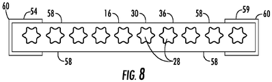
FIG. 8 is a cross-sectional view of another embodiment of an elevator belt. - Shown in
FIGS. 1A ,1B and1C are schematics of exemplarytraction elevator systems 10. Features of theelevator system 10 that are not required for an understanding of the present disclosure (such as the guide rails, safeties, etc.) are not discussed herein. Theelevator system 10 includes anelevator car 12 operatively suspended or supported in ahoistway 14 with one ormore belts 16. The one ormore belts 16 interact with one ormore sheaves 18 to be routed around various components of theelevator system 10. The one ormore belts 16 could also be connected to acounterweight 22, which is used to help balance theelevator system 10 and reduce the difference in belt tension on both sides of the traction sheave during operation. - The
sheaves 18 each have adiameter 20, which may be the same or different than the diameters of theother sheaves 18 in theelevator system 10. At least one of the sheaves would be atraction sheave 52. Thetraction sheave 52 is driven by amachine 50. Movement of drive sheave by themachine 50 drives, moves and/or propels (through traction) the one ormore belts 16 that are routed around thetraction sheave 52. - At least one of the
sheaves 18 could be a diverter, deflector or idler sheave. Diverter, deflector or idler sheaves are not driven by amachine 50, but help guide the one ormore belts 16 around the various components of theelevator system 10. - In some embodiments, the
elevator system 10 could use two ormore belts 16 for suspending and/or driving theelevator car 12. In addition, theelevator system 10 could have various configurations such that either both sides of the one ormore belts 16 engage the one or more sheaves 18 (such as shown in the exemplary elevator systems inFIGS. 1A ,1B or1C ) or only one side of the one ormore belts 16 engages the one or more sheaves 18. -
FIG. 1A provides a 1:1 roping arrangement in which the one ormore belts 16 terminate at thecar 12 andcounterweight 22.FIGS. 1B and1C provide different roping arrangements. Specifically,FIGS. 1B and1C show that thecar 12 and/or thecounterweight 22 can have one ormore sheaves 18 thereon engaging the one ormore belts 16 and the one ormore belts 16 can terminate elsewhere, typically at a structure within the hoistway 14 (such as for a machineroomless elevator system) or within the machine room (for elevator systems utilizing a machine room). The number ofsheaves 18 used in the arrangement determines the specific roping ratio (e.g. the 2:1 roping ratio shown inFIGS. 1B and1C or a different ratio).FIG 1C also provides a so-called rucksack or cantilevered type elevator. The present embodiments could also be used on elevator systems other than the exemplary types shown inFIGS. 1A ,1B and1C . - Referring to
FIG. 2 , a cross-sectional view of anexemplary belt 16 is shown. Thebelt 16 is constructed of one ormore cords 28 in ajacket 30. Thecords 28 of thebelt 16 may all be identical, or some or all of thecords 28 used in thebelt 16 could be different than theother cords 28. For example, one or more of thecords 28 could have a different construction, formed from different materials, or size than theother cords 28. As seen inFIG. 2 , thebelt 16 has an aspect ratio greater than one (i.e. belt width is greater than belt thickness). Referring toFIG. 3 , eachcord 28 comprises a plurality ofwires 32, which in some embodiments are formed intostrands 34, which are then formed into thecord 28. - Referring again to
FIG. 2 , thebelt 16 is constructed to have sufficient flexibility when passing over the one ormore sheaves 18 to provide low bending stresses, meet belt life requirements and have smooth operation, while being sufficiently strong to be capable of meeting strength requirements for suspending and/or driving theelevator car 12. - The
jacket 30 can substantially retain thecords 28 therein. The phrase substantially retain means that thejacket 30 has sufficient engagement with thecords 28 such that thecords 28 do not pull out of, detach from, and/or cut through thejacket 30 during the application on thebelt 16 of a load that can be encountered during use in anelevator system 10 with, potentially, an additional factor of safety. In other words, thecords 28 remain at their original positions relative to thejacket 30 during use in anelevator system 10. Thejacket 30 could completely envelop the cords 28 (such as shown inFIG. 2 ), substantially envelop thecords 28, or at least partially envelop thecords 28. - Referring now to
FIG. 4 , shown is an embodiment of abelt 16 having 10cords 28 arrayed along abelt width 40. Thebelt 16 is roughly rectangular in cross-section and in some embodiments abelt width 40 is in the range of 20-50 millimeters and a belt thickness 42 is in the range of 3-8 millimeters. Thejacket 30 includes atraction surface 36 interactive with and contacting the drive sheave 26 and aback surface 38 opposite thetraction surface 36. Theback surface 38 may be interactive withother sheaves 18, such as diverter, deflector or idler sheaves 18. One or more of thesheaves 18 may have a crowned sheave surface to steer or guide thebelt 16. The crownedsheave surface 18, alone or in combination with other factors, results in uneven pressure on thetraction surface 36 and/or theback surface 38 causing uneven slip and/ or wear of thebelt 16. Referring again toFIG. 4 , thebelt 16 includes material strips 46 on thetraction surface 36 to counteract high wear of select portions of thetraction surface 36 due to, for example, uneven pressure on thetraction surface 36 during operation of theelevator system 10. In one embodiment, the material strips are applied overcord 28b andcord 28i, corresponding to anticipated high levels of wear in those areas ofbelt 16. The material strips 46 are configured to counteract high levels of wear and may be formed from, for example, a wear resistant elastomer, a wear resistant fabric or an elastomer with higher or lower friction properties to raise or lower the friction and traction of thebelt 16. In particular, a lower friction material is beneficial to help reduce wear of thebelt 16, and may include a damped material to reducebelt 16 noise during operation. Further, in some embodiments, material strips 46 may be utilized not only at thetraction surface 36 but at theback surface 38 in addition to or as an alternative tomaterial strips 46 at thetraction surface 36. In some embodiments, the material strips 46 cover 5% to 50% of thetraction surface 36. Application of material strips 46 is not limited to overcord traction surface 36 and/or theback surface 38. For example, in some embodiments, amaterial strip 46 of a low coefficient of friction material may be applied at a center of thetraction surface 36 to promote microslip at thebelt 16 center, while reducing microslip at outboard regions of thebelt 16. In some embodiments, material strips 46 indifferent belt 16 locations may be formed from different materials to enhance different properties of thebelt 16 operation. - The
jacket 30 and material strips 46 may be formed from of any of but not limited to the following materials: polyurethane, styrene butadiene rubbers, nitrile rubber, neoprene, fluoroelastomer, silicone rubber, room temperature vulcanizates, natural rubber, EPDM. - Materials utilized in the
jacket 30 and/or the material strips 46 may have additives which influence friction, traction and wear properties. These additives may include but are not limited to small molecule additives such as liquids, oils, paraphinic waxes, ionic liquids, fire retardants etc. Other additives could also include blends of other polymers, or particulate additives such as inorganics (clay, glass, etc.) or organics (rubber, etc.). Any combination of additives can be incorporated at a range of total additive concentration from 0.001 wt.% to 50 wt. %; more specifically 0.01 wt.% to 25 wt.% and even more specifically 0.01wt.% to 15 wt.%. - In some embodiments, as shown in
FIG. 4 , the material strips 46 are applied over thetraction surface 36, and may be added during the extrusion process used to form thejacket 30 over thecords 28. Alternatively, the material strips 46 may be imparted to thetraction surface 36 during a mold wheel operation, after extrusion of thejacket 30. Referring now toFIG. 5 , in some embodiments, agroove 48 is formed in thejacket 30, either during extrusion or in a post-extrusion process. Anadditive material 54 is added into thegroove 48 to change thebelt 16 performance, reducing wear of thebelt 16, compared to a belt without theadditive material 54 of the material strips 46. Theadditive material 54 is added in a post extrusion process, such as thermal fusion or adhesion of a secondary tape or fabric including theadditive material 54 to thegroove 48. This allows for standardization of thejacket 30 manufacturing process and also the manufacturing process of theadditive material 54. Theadditive material 54 may include fluoropolymers, polyesters or other thermoplastic materials. Additional exemplary materials include uncoated or coated fabrics, such as Kevlar, graphite, urethane, rubber or other materials to modify friction properties of thebelt 16. Further, in some embodiments, theadditive material 54 may be utilized not only at thetraction surface 36 but at theback surface 38. - Referring now to
FIG. 6 , in some embodiments, thegroove 48 may have an interlockingnotch 56 extending outwardly from thegroove 48, into which theadditive material 54 may be inserted to lock theadditive material 54 in place at thegroove 48. In an alternate embodiment, the locking feature of 54 is preformed in the second material and integrated into thebelt 16 during the primary extrusion operation of the jacket material. - In another embodiment, as illustrated in
FIG. 7 , thebelt 16 may includeundercuts 58 where material is removed from thejacket 30 in locations where high degrees of wear are predicted. Such configurations move high pressure and/or slip to other locations along thebelt 16. In addition,belt 16 thickness may be enhanced in other regions, such as belt width ends 60. Wear in the normal wear track, such as atcords jacket 30 and/or via a secondary process. In some embodiments, such as shown inFIG. 8 , theadditive materials 54 may be wrapped around an edge surface 62 of thebelt 16 from thetraction surface 36 to theback surface 38. - The configurations disclosed herein allow for modifications to a
base belt 16 configuration to address performance issues such as wear, slip and noise through the use of added features such as material strips 46 andadditive materials 54. These features may be added without changing the manufacturing processes of thebaseline belt 16. - While the disclosure has been described in detail in connection with only a limited number of embodiments, it should be readily understood that the disclosure is not limited to such disclosed embodiments. Rather, the disclosure can be modified to incorporate any number of variations, alterations, substitutions or equivalent arrangements not heretofore described, but which are commensurate with the spirit and scope of the disclosure. Additionally, while various embodiments have been described, it is to be understood that aspects of the disclosure may include only some of the described embodiments. Accordingly, the disclosure is not to be seen as limited by the foregoing description, but is only limited by the scope of the appended claims.
Claims (15)
- A belt for suspending and/or driving an elevator car, comprising:a plurality of tension elements extending longitudinally along a length of the belt;a jacket at least partially encapsulating the plurality of tension elements, the jacket defining a traction surface of the belt configured to be interactive with a drive sheave and a back surface opposite the traction surface, the jacket formed from a first material; andone or more material strips disposed at one or more of the traction surface or the back surface to improve one or more operational characteristics of the belt, the one or more material strips formed from a second material different from the first material.
- The belt of claim 1, wherein the second material is configured to counteract wear of the belt, and/or
wherein the second material is one of a wear resistant elastomer, a wear resistant fabric or an elastomer having friction properties different from the first material. - The belt of claim 1 or 2, wherein the one or more material strips are applied over the traction surface.
- The belt of any preceding claim, further comprising one or more grooves formed in the jacket, wherein the one or more material strips are inserted into the one or more grooves.
- The belt of any preceding claim, wherein the jacket includes a retaining feature to mechanically connect the one or more material strips to the jacket.
- The belt of any preceding claim, further comprising one or more material strips disposed at the back surface of the belt, opposite the traction surface.
- The belt of any preceding claim, further comprising one or more undercuts in the jacket in regions of predicted wear, wherein optionally the one or more material strips are located at one or more belt width ends.
- The belt of any preceding claim, wherein one or more of the jacket or the material strips are formed from one or more of polyurethane, styrene butadiene rubber, nitrile rubber, neoprene, fluoroelastomer, silicone rubber, room temperature vulcanizate, natural rubber, or EPDM, and/or
wherein one or more of the jacket or the material strips include one or more additives of small molecule additives such as liquids, oils, paraphinic waxes, ionic liquids, fire retardants, or particulate additives such as inorganics or organics. - An elevator system, comprising:a hoistway;an elevator car disposed in the hoistway, and drivable along the hoistway;a drive sheave disposed in the hoistway; anda belt operably connected to the elevator car and the drive sheave to drive the elevator car along the hoistway, the belt including:a plurality of tension elements extending longitudinally along a length of the belt;a jacket at least partially encapsulating the plurality of tension elements, the jacket defining a traction surface of the belt configured to be interactive with the drive sheave and a back surface opposite the traction surface, the jacket formed from a first material; andone or more material strips disposed at one or more of the traction surface or the back surface to improve one or more operational characteristics of the belt, the one or more material strips formed from a second material different from the first material.
- The elevator system of claim 9, wherein the second material is configured to counteract wear of the belt, and/or
wherein the second material is one of a wear resistant elastomer, a wear resistant fabric or an elastomer having friction properties different from the first material. - The elevator system of claim 9 or 10, wherein the one or more material strips are applied over the traction surface.
- The elevator system of any of claims 9-11, further comprising:one or more grooves formed in the jacket, wherein the one or more material strips are inserted into the one or more grooves.
- The elevator system of any of claims 9-12, wherein the jacket includes a retaining feature to mechanically connect the one or more material strips to the jacket
- The elevator system of any of claims 9-13, further comprising one or more material strips disposed at a back surface of the belt, opposite the traction surface.
- The elevator system of any of claims 9-14, further comprising one or more undercuts in the jacket in regions of predicted wear, and optionally further comprising locating the one or more material strips at one or more belt width ends.
Applications Claiming Priority (2)
| Application Number | Priority Date | Filing Date | Title |
|---|---|---|---|
| US201662293078P | 2016-02-09 | 2016-02-09 | |
| US15/412,537 US10556775B2 (en) | 2016-02-09 | 2017-01-23 | Surface construction of elevator belt |
Publications (2)
| Publication Number | Publication Date |
|---|---|
| EP3205616A1 true EP3205616A1 (en) | 2017-08-16 |
| EP3205616B1 EP3205616B1 (en) | 2020-07-01 |
Family
ID=57995152
Family Applications (1)
| Application Number | Title | Priority Date | Filing Date |
|---|---|---|---|
| EP17155282.1A Active EP3205616B1 (en) | 2016-02-09 | 2017-02-08 | Surface construction of elevator belt |
Country Status (3)
| Country | Link |
|---|---|
| US (1) | US10556775B2 (en) |
| EP (1) | EP3205616B1 (en) |
| CN (1) | CN107043058B (en) |
Cited By (1)
| Publication number | Priority date | Publication date | Assignee | Title |
|---|---|---|---|---|
| EP3514095A1 (en) * | 2018-01-15 | 2019-07-24 | Otis Elevator Company | Wear detection of elevator belt |
Families Citing this family (9)
| Publication number | Priority date | Publication date | Assignee | Title |
|---|---|---|---|---|
| US9873593B2 (en) * | 2015-05-07 | 2018-01-23 | Otis Elevator Company | Fire resistant coated steel belt |
| US10974929B2 (en) * | 2016-11-07 | 2021-04-13 | Otis Elevator Company | Load bearing member for an elevator system having an elastomer and phosphonate blended bonding agent |
| US20190062114A1 (en) * | 2017-08-25 | 2019-02-28 | Otis Elevator Company | Self-extinguishing load bearing member for elevator system |
| US10549952B2 (en) * | 2017-08-25 | 2020-02-04 | Otis Elevator Company | Self-extinguishing fabric belt for elevator system |
| US11584619B2 (en) * | 2018-01-15 | 2023-02-21 | Otis Elevator Company | Reinforced jacket for belt |
| US11535498B2 (en) * | 2018-05-17 | 2022-12-27 | Liftwave, Inc. | Fleet and twist tolerant flat belt design |
| US10926976B2 (en) * | 2018-06-18 | 2021-02-23 | Otis Elevator Company | Belt with corrugated material |
| US11407616B2 (en) * | 2020-01-24 | 2022-08-09 | Otis Elevator Company | Elevator belt surface protection for installation |
| CN113060623B (en) * | 2021-04-21 | 2022-11-15 | 浙江力石工程有限公司 | Top supporting beam of car elevator |
Citations (3)
| Publication number | Priority date | Publication date | Assignee | Title |
|---|---|---|---|---|
| US20040083707A1 (en) * | 2002-01-11 | 2004-05-06 | Roland Eichhorn | Rope of synthetic fiber with reinforcement element for frictionally engaged power transmission and rope of synthetic fiber with reinforcement element for positively engaged power transmission |
| US20110259677A1 (en) * | 2010-04-22 | 2011-10-27 | Dudde Frank P | Elevator suspension and transmission strip |
| US20130037353A1 (en) * | 2011-08-09 | 2013-02-14 | Brugg Drahtseil Ag | Traction member having traction control |
Family Cites Families (26)
| Publication number | Priority date | Publication date | Assignee | Title |
|---|---|---|---|---|
| JPS593011B2 (en) | 1978-05-23 | 1984-01-21 | 株式会社フジクラ | flat power supply cable |
| WO1998029327A1 (en) | 1996-12-30 | 1998-07-09 | Kone Corporation | Elevator rope arrangement |
| US6401871B2 (en) | 1998-02-26 | 2002-06-11 | Otis Elevator Company | Tension member for an elevator |
| WO1999043589A1 (en) | 1998-02-26 | 1999-09-02 | Otis Elevator Company | Elevator system having drive motor located between elevator car and hoistway sidewall |
| US6672046B1 (en) | 1999-08-26 | 2004-01-06 | Otis Elevator Company | Tension member for an elevator |
| US7670240B2 (en) | 2001-10-04 | 2010-03-02 | Otis Elevator Company | Elevator belt assembly with noise reducing groove arrangement |
| US8444515B2 (en) | 2001-11-13 | 2013-05-21 | Otis Elevator Company | Elevator belt assembly with noise and vibration reducing grooveless jacket arrangement |
| CN1668793B (en) | 2002-09-25 | 2013-11-20 | 奥蒂斯电梯公司 | Elevator belt assembly with pre-stretched synthetic cords |
| ES2353504T5 (en) | 2004-03-15 | 2018-04-30 | Otis Elevator Company | Method of manufacturing an elevator load bearing member having a wrap with at least one rough outer surface |
| ES2402930T5 (en) | 2005-09-13 | 2016-12-05 | Otis Elevator Company | Method of manufacturing a load bearing element for an elevator system |
| WO2008110241A2 (en) * | 2007-03-12 | 2008-09-18 | Inventio Ag | Elevator system, carrying means for an elevator system, and method for the production of a carrying means |
| DE102007021434B4 (en) | 2007-05-08 | 2018-10-18 | Contitech Antriebssysteme Gmbh | Aufzugsanlagenzugmittel |
| GB2458001B (en) | 2008-01-18 | 2010-12-08 | Kone Corp | An elevator hoist rope, an elevator and method |
| DE102008037538A1 (en) | 2008-11-10 | 2010-05-12 | Contitech Antriebssysteme Gmbh | Traction system for an elevator installation |
| EP2356054B1 (en) | 2008-11-14 | 2014-04-02 | Otis Elevator Company | Elevator belt and corresponding method of making the same |
| CN101875467B (en) | 2010-03-29 | 2012-05-23 | 江南嘉捷电梯股份有限公司 | Traction belt for elevators |
| WO2012025278A1 (en) | 2010-08-27 | 2012-03-01 | Sgl Carbon Se | Load-pulling system |
| EP2688827A4 (en) | 2011-03-21 | 2014-11-19 | Otis Elevator Co | Elevator tension member |
| ES2575691T3 (en) | 2011-06-10 | 2016-06-30 | Otis Elevator Company | Elevator tension member and production method |
| CN202247494U (en) | 2011-08-02 | 2012-05-30 | 葛文国 | elevator traction belt |
| FI123534B (en) | 2012-02-13 | 2013-06-28 | Kone Corp | Rope for a lifting device, elevator and method for making a rope |
| WO2014014456A1 (en) * | 2012-07-18 | 2014-01-23 | Otis Elevator Company | Fire-retardant belt |
| ES2609467T3 (en) | 2013-10-10 | 2017-04-20 | Kone Corporation | Cable for a lifting and lifting device |
| EP2913288A1 (en) * | 2014-02-28 | 2015-09-02 | Inventio AG | Support for an elevator |
| US9873593B2 (en) * | 2015-05-07 | 2018-01-23 | Otis Elevator Company | Fire resistant coated steel belt |
| ES2828441T3 (en) * | 2016-12-29 | 2021-05-26 | Kone Corp | Cable arrangement and lifting device |
-
2017
- 2017-01-23 US US15/412,537 patent/US10556775B2/en active Active
- 2017-02-08 EP EP17155282.1A patent/EP3205616B1/en active Active
- 2017-02-08 CN CN201710070143.3A patent/CN107043058B/en active Active
Patent Citations (3)
| Publication number | Priority date | Publication date | Assignee | Title |
|---|---|---|---|---|
| US20040083707A1 (en) * | 2002-01-11 | 2004-05-06 | Roland Eichhorn | Rope of synthetic fiber with reinforcement element for frictionally engaged power transmission and rope of synthetic fiber with reinforcement element for positively engaged power transmission |
| US20110259677A1 (en) * | 2010-04-22 | 2011-10-27 | Dudde Frank P | Elevator suspension and transmission strip |
| US20130037353A1 (en) * | 2011-08-09 | 2013-02-14 | Brugg Drahtseil Ag | Traction member having traction control |
Cited By (2)
| Publication number | Priority date | Publication date | Assignee | Title |
|---|---|---|---|---|
| EP3514095A1 (en) * | 2018-01-15 | 2019-07-24 | Otis Elevator Company | Wear detection of elevator belt |
| US11001474B2 (en) | 2018-01-15 | 2021-05-11 | Otis Elevator Company | Wear detection of elevator belt |
Also Published As
| Publication number | Publication date |
|---|---|
| US10556775B2 (en) | 2020-02-11 |
| CN107043058A (en) | 2017-08-15 |
| EP3205616B1 (en) | 2020-07-01 |
| CN107043058B (en) | 2021-04-27 |
| US20170225925A1 (en) | 2017-08-10 |
Similar Documents
| Publication | Publication Date | Title |
|---|---|---|
| US10556775B2 (en) | Surface construction of elevator belt | |
| US9050768B2 (en) | Method and device for producing a support belt for an elevator installation | |
| US9617118B2 (en) | Elevator suspension and/or driving assembly having at least one traction surface defined by weave fibers | |
| US10604379B2 (en) | Elevator system belt with fabric tension member | |
| US11584619B2 (en) | Reinforced jacket for belt | |
| EP3071504B1 (en) | Idler or deflector sheave for elevator system | |
| EP3447019B1 (en) | Belt with self-extinguishing layer and method of making | |
| KR20080014697A (en) | Elevator belts for hoisting equipment and methods of manufacturing such elevator belts | |
| US11247871B2 (en) | Elevator system belt | |
| CN101044084A (en) | Lift comprising a flat belt as a tractive element | |
| EP3447018A1 (en) | Self-extinguishing load bearing member for elevator system | |
| JP2018177533A (en) | Tension member for a belt of an elevator system | |
| CN110615341B (en) | Belt with corrugated material | |
| US20190047821A1 (en) | Load bearing member for lifting system | |
| US20240262655A1 (en) | Elevator system belt | |
| CN112551308B (en) | Trench belt for elevator system | |
| EP2969877B1 (en) | Asymmetric and steered sheaves for twisted multi-belt elevator systems | |
| US20180179023A1 (en) | Increased traction of elevator system belt | |
| EP3450377B1 (en) | Sheave for belt with profile tracking features | |
| HK1181024B (en) | Elevator suspension and/or driving assembly having at least one traction surface defined by weave fibers |
Legal Events
| Date | Code | Title | Description |
|---|---|---|---|
| PUAI | Public reference made under article 153(3) epc to a published international application that has entered the european phase |
Free format text: ORIGINAL CODE: 0009012 |
|
| STAA | Information on the status of an ep patent application or granted ep patent |
Free format text: STATUS: THE APPLICATION HAS BEEN PUBLISHED |
|
| AK | Designated contracting states |
Kind code of ref document: A1 Designated state(s): AL AT BE BG CH CY CZ DE DK EE ES FI FR GB GR HR HU IE IS IT LI LT LU LV MC MK MT NL NO PL PT RO RS SE SI SK SM TR |
|
| AX | Request for extension of the european patent |
Extension state: BA ME |
|
| RAP1 | Party data changed (applicant data changed or rights of an application transferred) |
Owner name: OTIS ELEVATOR COMPANY |
|
| STAA | Information on the status of an ep patent application or granted ep patent |
Free format text: STATUS: REQUEST FOR EXAMINATION WAS MADE |
|
| 17P | Request for examination filed |
Effective date: 20180216 |
|
| RBV | Designated contracting states (corrected) |
Designated state(s): AL AT BE BG CH CY CZ DE DK EE ES FI FR GB GR HR HU IE IS IT LI LT LU LV MC MK MT NL NO PL PT RO RS SE SI SK SM TR |
|
| STAA | Information on the status of an ep patent application or granted ep patent |
Free format text: STATUS: EXAMINATION IS IN PROGRESS |
|
| 17Q | First examination report despatched |
Effective date: 20190225 |
|
| GRAP | Despatch of communication of intention to grant a patent |
Free format text: ORIGINAL CODE: EPIDOSNIGR1 |
|
| STAA | Information on the status of an ep patent application or granted ep patent |
Free format text: STATUS: GRANT OF PATENT IS INTENDED |
|
| RIC1 | Information provided on ipc code assigned before grant |
Ipc: B66B 7/06 20060101AFI20191209BHEP Ipc: D07B 1/16 20060101ALI20191209BHEP Ipc: D07B 5/00 20060101ALI20191209BHEP |
|
| INTG | Intention to grant announced |
Effective date: 20200113 |
|
| GRAS | Grant fee paid |
Free format text: ORIGINAL CODE: EPIDOSNIGR3 |
|
| GRAA | (expected) grant |
Free format text: ORIGINAL CODE: 0009210 |
|
| STAA | Information on the status of an ep patent application or granted ep patent |
Free format text: STATUS: THE PATENT HAS BEEN GRANTED |
|
| AK | Designated contracting states |
Kind code of ref document: B1 Designated state(s): AL AT BE BG CH CY CZ DE DK EE ES FI FR GB GR HR HU IE IS IT LI LT LU LV MC MK MT NL NO PL PT RO RS SE SI SK SM TR |
|
| REG | Reference to a national code |
Ref country code: AT Ref legal event code: REF Ref document number: 1286011 Country of ref document: AT Kind code of ref document: T Effective date: 20200715 Ref country code: CH Ref legal event code: EP |
|
| REG | Reference to a national code |
Ref country code: IE Ref legal event code: FG4D |
|
| REG | Reference to a national code |
Ref country code: DE Ref legal event code: R096 Ref document number: 602017018866 Country of ref document: DE |
|
| REG | Reference to a national code |
Ref country code: LT Ref legal event code: MG4D |
|
| PG25 | Lapsed in a contracting state [announced via postgrant information from national office to epo] |
Ref country code: BG Free format text: LAPSE BECAUSE OF FAILURE TO SUBMIT A TRANSLATION OF THE DESCRIPTION OR TO PAY THE FEE WITHIN THE PRESCRIBED TIME-LIMIT Effective date: 20201001 |
|
| REG | Reference to a national code |
Ref country code: NL Ref legal event code: MP Effective date: 20200701 |
|
| REG | Reference to a national code |
Ref country code: AT Ref legal event code: MK05 Ref document number: 1286011 Country of ref document: AT Kind code of ref document: T Effective date: 20200701 |
|
| PG25 | Lapsed in a contracting state [announced via postgrant information from national office to epo] |
Ref country code: HR Free format text: LAPSE BECAUSE OF FAILURE TO SUBMIT A TRANSLATION OF THE DESCRIPTION OR TO PAY THE FEE WITHIN THE PRESCRIBED TIME-LIMIT Effective date: 20200701 Ref country code: LT Free format text: LAPSE BECAUSE OF FAILURE TO SUBMIT A TRANSLATION OF THE DESCRIPTION OR TO PAY THE FEE WITHIN THE PRESCRIBED TIME-LIMIT Effective date: 20200701 Ref country code: FI Free format text: LAPSE BECAUSE OF FAILURE TO SUBMIT A TRANSLATION OF THE DESCRIPTION OR TO PAY THE FEE WITHIN THE PRESCRIBED TIME-LIMIT Effective date: 20200701 Ref country code: CZ Free format text: LAPSE BECAUSE OF FAILURE TO SUBMIT A TRANSLATION OF THE DESCRIPTION OR TO PAY THE FEE WITHIN THE PRESCRIBED TIME-LIMIT Effective date: 20200701 Ref country code: AT Free format text: LAPSE BECAUSE OF FAILURE TO SUBMIT A TRANSLATION OF THE DESCRIPTION OR TO PAY THE FEE WITHIN THE PRESCRIBED TIME-LIMIT Effective date: 20200701 Ref country code: PT Free format text: LAPSE BECAUSE OF FAILURE TO SUBMIT A TRANSLATION OF THE DESCRIPTION OR TO PAY THE FEE WITHIN THE PRESCRIBED TIME-LIMIT Effective date: 20201102 Ref country code: ES Free format text: LAPSE BECAUSE OF FAILURE TO SUBMIT A TRANSLATION OF THE DESCRIPTION OR TO PAY THE FEE WITHIN THE PRESCRIBED TIME-LIMIT Effective date: 20200701 Ref country code: GR Free format text: LAPSE BECAUSE OF FAILURE TO SUBMIT A TRANSLATION OF THE DESCRIPTION OR TO PAY THE FEE WITHIN THE PRESCRIBED TIME-LIMIT Effective date: 20201002 Ref country code: SE Free format text: LAPSE BECAUSE OF FAILURE TO SUBMIT A TRANSLATION OF THE DESCRIPTION OR TO PAY THE FEE WITHIN THE PRESCRIBED TIME-LIMIT Effective date: 20200701 Ref country code: NO Free format text: LAPSE BECAUSE OF FAILURE TO SUBMIT A TRANSLATION OF THE DESCRIPTION OR TO PAY THE FEE WITHIN THE PRESCRIBED TIME-LIMIT Effective date: 20201001 |
|
| PG25 | Lapsed in a contracting state [announced via postgrant information from national office to epo] |
Ref country code: IS Free format text: LAPSE BECAUSE OF FAILURE TO SUBMIT A TRANSLATION OF THE DESCRIPTION OR TO PAY THE FEE WITHIN THE PRESCRIBED TIME-LIMIT Effective date: 20201101 Ref country code: RS Free format text: LAPSE BECAUSE OF FAILURE TO SUBMIT A TRANSLATION OF THE DESCRIPTION OR TO PAY THE FEE WITHIN THE PRESCRIBED TIME-LIMIT Effective date: 20200701 Ref country code: LV Free format text: LAPSE BECAUSE OF FAILURE TO SUBMIT A TRANSLATION OF THE DESCRIPTION OR TO PAY THE FEE WITHIN THE PRESCRIBED TIME-LIMIT Effective date: 20200701 Ref country code: PL Free format text: LAPSE BECAUSE OF FAILURE TO SUBMIT A TRANSLATION OF THE DESCRIPTION OR TO PAY THE FEE WITHIN THE PRESCRIBED TIME-LIMIT Effective date: 20200701 |
|
| PG25 | Lapsed in a contracting state [announced via postgrant information from national office to epo] |
Ref country code: NL Free format text: LAPSE BECAUSE OF FAILURE TO SUBMIT A TRANSLATION OF THE DESCRIPTION OR TO PAY THE FEE WITHIN THE PRESCRIBED TIME-LIMIT Effective date: 20200701 |
|
| REG | Reference to a national code |
Ref country code: DE Ref legal event code: R097 Ref document number: 602017018866 Country of ref document: DE |
|
| PG25 | Lapsed in a contracting state [announced via postgrant information from national office to epo] |
Ref country code: DK Free format text: LAPSE BECAUSE OF FAILURE TO SUBMIT A TRANSLATION OF THE DESCRIPTION OR TO PAY THE FEE WITHIN THE PRESCRIBED TIME-LIMIT Effective date: 20200701 Ref country code: RO Free format text: LAPSE BECAUSE OF FAILURE TO SUBMIT A TRANSLATION OF THE DESCRIPTION OR TO PAY THE FEE WITHIN THE PRESCRIBED TIME-LIMIT Effective date: 20200701 Ref country code: SM Free format text: LAPSE BECAUSE OF FAILURE TO SUBMIT A TRANSLATION OF THE DESCRIPTION OR TO PAY THE FEE WITHIN THE PRESCRIBED TIME-LIMIT Effective date: 20200701 Ref country code: IT Free format text: LAPSE BECAUSE OF FAILURE TO SUBMIT A TRANSLATION OF THE DESCRIPTION OR TO PAY THE FEE WITHIN THE PRESCRIBED TIME-LIMIT Effective date: 20200701 Ref country code: EE Free format text: LAPSE BECAUSE OF FAILURE TO SUBMIT A TRANSLATION OF THE DESCRIPTION OR TO PAY THE FEE WITHIN THE PRESCRIBED TIME-LIMIT Effective date: 20200701 |
|
| PLBE | No opposition filed within time limit |
Free format text: ORIGINAL CODE: 0009261 |
|
| STAA | Information on the status of an ep patent application or granted ep patent |
Free format text: STATUS: NO OPPOSITION FILED WITHIN TIME LIMIT |
|
| PG25 | Lapsed in a contracting state [announced via postgrant information from national office to epo] |
Ref country code: AL Free format text: LAPSE BECAUSE OF FAILURE TO SUBMIT A TRANSLATION OF THE DESCRIPTION OR TO PAY THE FEE WITHIN THE PRESCRIBED TIME-LIMIT Effective date: 20200701 |
|
| 26N | No opposition filed |
Effective date: 20210406 |
|
| PG25 | Lapsed in a contracting state [announced via postgrant information from national office to epo] |
Ref country code: SK Free format text: LAPSE BECAUSE OF FAILURE TO SUBMIT A TRANSLATION OF THE DESCRIPTION OR TO PAY THE FEE WITHIN THE PRESCRIBED TIME-LIMIT Effective date: 20200701 |
|
| PG25 | Lapsed in a contracting state [announced via postgrant information from national office to epo] |
Ref country code: SI Free format text: LAPSE BECAUSE OF FAILURE TO SUBMIT A TRANSLATION OF THE DESCRIPTION OR TO PAY THE FEE WITHIN THE PRESCRIBED TIME-LIMIT Effective date: 20200701 |
|
| PG25 | Lapsed in a contracting state [announced via postgrant information from national office to epo] |
Ref country code: MC Free format text: LAPSE BECAUSE OF FAILURE TO SUBMIT A TRANSLATION OF THE DESCRIPTION OR TO PAY THE FEE WITHIN THE PRESCRIBED TIME-LIMIT Effective date: 20200701 |
|
| GBPC | Gb: european patent ceased through non-payment of renewal fee |
Effective date: 20210208 |
|
| REG | Reference to a national code |
Ref country code: BE Ref legal event code: MM Effective date: 20210228 |
|
| PG25 | Lapsed in a contracting state [announced via postgrant information from national office to epo] |
Ref country code: LU Free format text: LAPSE BECAUSE OF NON-PAYMENT OF DUE FEES Effective date: 20210208 Ref country code: LI Free format text: LAPSE BECAUSE OF NON-PAYMENT OF DUE FEES Effective date: 20210228 Ref country code: CH Free format text: LAPSE BECAUSE OF NON-PAYMENT OF DUE FEES Effective date: 20210228 |
|
| PG25 | Lapsed in a contracting state [announced via postgrant information from national office to epo] |
Ref country code: IE Free format text: LAPSE BECAUSE OF NON-PAYMENT OF DUE FEES Effective date: 20210208 Ref country code: GB Free format text: LAPSE BECAUSE OF NON-PAYMENT OF DUE FEES Effective date: 20210208 |
|
| PG25 | Lapsed in a contracting state [announced via postgrant information from national office to epo] |
Ref country code: BE Free format text: LAPSE BECAUSE OF NON-PAYMENT OF DUE FEES Effective date: 20210228 |
|
| PG25 | Lapsed in a contracting state [announced via postgrant information from national office to epo] |
Ref country code: HU Free format text: LAPSE BECAUSE OF FAILURE TO SUBMIT A TRANSLATION OF THE DESCRIPTION OR TO PAY THE FEE WITHIN THE PRESCRIBED TIME-LIMIT; INVALID AB INITIO Effective date: 20170208 |
|
| PG25 | Lapsed in a contracting state [announced via postgrant information from national office to epo] |
Ref country code: CY Free format text: LAPSE BECAUSE OF FAILURE TO SUBMIT A TRANSLATION OF THE DESCRIPTION OR TO PAY THE FEE WITHIN THE PRESCRIBED TIME-LIMIT Effective date: 20200701 |
|
| PG25 | Lapsed in a contracting state [announced via postgrant information from national office to epo] |
Ref country code: MK Free format text: LAPSE BECAUSE OF FAILURE TO SUBMIT A TRANSLATION OF THE DESCRIPTION OR TO PAY THE FEE WITHIN THE PRESCRIBED TIME-LIMIT Effective date: 20200701 |
|
| PG25 | Lapsed in a contracting state [announced via postgrant information from national office to epo] |
Ref country code: TR Free format text: LAPSE BECAUSE OF FAILURE TO SUBMIT A TRANSLATION OF THE DESCRIPTION OR TO PAY THE FEE WITHIN THE PRESCRIBED TIME-LIMIT Effective date: 20200701 |
|
| PG25 | Lapsed in a contracting state [announced via postgrant information from national office to epo] |
Ref country code: MT Free format text: LAPSE BECAUSE OF FAILURE TO SUBMIT A TRANSLATION OF THE DESCRIPTION OR TO PAY THE FEE WITHIN THE PRESCRIBED TIME-LIMIT Effective date: 20200701 |
|
| PGFP | Annual fee paid to national office [announced via postgrant information from national office to epo] |
Ref country code: DE Payment date: 20250122 Year of fee payment: 9 |
|
| PGFP | Annual fee paid to national office [announced via postgrant information from national office to epo] |
Ref country code: FR Payment date: 20250122 Year of fee payment: 9 |