EP3205574A2 - Structural, cellular core with corrugated support walls - Google Patents
Structural, cellular core with corrugated support walls Download PDFInfo
- Publication number
- EP3205574A2 EP3205574A2 EP17155552.7A EP17155552A EP3205574A2 EP 3205574 A2 EP3205574 A2 EP 3205574A2 EP 17155552 A EP17155552 A EP 17155552A EP 3205574 A2 EP3205574 A2 EP 3205574A2
- Authority
- EP
- European Patent Office
- Prior art keywords
- skin
- cavities
- wall
- vertical
- baffles
- Prior art date
- Legal status (The legal status is an assumption and is not a legal conclusion. Google has not performed a legal analysis and makes no representation as to the accuracy of the status listed.)
- Granted
Links
Images


Classifications
-
- B—PERFORMING OPERATIONS; TRANSPORTING
- B64—AIRCRAFT; AVIATION; COSMONAUTICS
- B64C—AEROPLANES; HELICOPTERS
- B64C1/00—Fuselages; Constructional features common to fuselages, wings, stabilising surfaces or the like
- B64C1/40—Sound or heat insulation, e.g. using insulation blankets
-
- B—PERFORMING OPERATIONS; TRANSPORTING
- B64—AIRCRAFT; AVIATION; COSMONAUTICS
- B64C—AEROPLANES; HELICOPTERS
- B64C1/00—Fuselages; Constructional features common to fuselages, wings, stabilising surfaces or the like
- B64C1/06—Frames; Stringers; Longerons ; Fuselage sections
- B64C1/066—Interior liners
-
- B—PERFORMING OPERATIONS; TRANSPORTING
- B64—AIRCRAFT; AVIATION; COSMONAUTICS
- B64D—EQUIPMENT FOR FITTING IN OR TO AIRCRAFT; FLIGHT SUITS; PARACHUTES; ARRANGEMENT OR MOUNTING OF POWER PLANTS OR PROPULSION TRANSMISSIONS IN AIRCRAFT
- B64D29/00—Power-plant nacelles, fairings or cowlings
-
- G—PHYSICS
- G10—MUSICAL INSTRUMENTS; ACOUSTICS
- G10K—SOUND-PRODUCING DEVICES; METHODS OR DEVICES FOR PROTECTING AGAINST, OR FOR DAMPING, NOISE OR OTHER ACOUSTIC WAVES IN GENERAL; ACOUSTICS NOT OTHERWISE PROVIDED FOR
- G10K11/00—Methods or devices for transmitting, conducting or directing sound in general; Methods or devices for protecting against, or for damping, noise or other acoustic waves in general
- G10K11/16—Methods or devices for protecting against, or for damping, noise or other acoustic waves in general
- G10K11/162—Selection of materials
- G10K11/168—Plural layers of different materials, e.g. sandwiches
-
- G—PHYSICS
- G10—MUSICAL INSTRUMENTS; ACOUSTICS
- G10K—SOUND-PRODUCING DEVICES; METHODS OR DEVICES FOR PROTECTING AGAINST, OR FOR DAMPING, NOISE OR OTHER ACOUSTIC WAVES IN GENERAL; ACOUSTICS NOT OTHERWISE PROVIDED FOR
- G10K11/00—Methods or devices for transmitting, conducting or directing sound in general; Methods or devices for protecting against, or for damping, noise or other acoustic waves in general
- G10K11/16—Methods or devices for protecting against, or for damping, noise or other acoustic waves in general
- G10K11/172—Methods or devices for protecting against, or for damping, noise or other acoustic waves in general using resonance effects
Definitions
- Acoustic panels may be used in various applications to attenuate noise.
- An acoustic panel for example, may be configured with a nacelle of an aircraft propulsion system to attenuate noise generated by a gas turbine engine.
- Such an acoustic panel typically includes a honeycomb core connected between a perforated face skin and a solid, non-perforated back skin.
- the honeycomb core includes a plurality of resonating chambers. These resonating chambers are tuned by selecting a desired chamber length and, thus, core thickness that corresponds to a specific target frequency of noise to be attenuated.
- a structural panel which may be configured for attenuating noise.
- This panel includes a first skin, a second skin and a core.
- the core forms a plurality of cavities vertically between the first skin and the second skin.
- the core includes a wall connected to and extending vertically between the first skin and the second skin.
- the wall is laterally between and fluidly separates at least a first of the cavities from a second of the cavities.
- the wall includes a vertical stiffener.
- One or more perforations in the first skin are fluidly coupled with the first of the cavities.
- this panel includes a first skin, a second skin and a core.
- the core forms a plurality of cavities vertically between the first skin and the second skin.
- the core includes a plurality of walls connected to and extending vertically between the first skin and the second skin.
- a first of the walls is laterally between and fluidly separates at least a first of the cavities from a second of the cavities.
- a second of the walls is laterally between and fluidly separates at least the first of the cavities from a third of the cavities.
- Each of the walls includes a vertical stiffener. The vertical stiffener of the first of the walls projects partially laterally into the first of the cavities.
- One or more perforations in the first skin are fluidly coupled with the first of the cavities.
- the vertical stiffener may be one of a plurality of vertical stiffeners included with the wall.
- One of the vertical stiffeners may be disposed a longitudinal distance along the wall from an adjacent one of the vertical stiffeners.
- the vertical stiffener may be configured as an accordion bellow.
- the cellular core 26 extends laterally and longitudinally along the x-y plane (see FIG. 1 ).
- the cellular core 26 has a vertical thickness 34, which extends vertically between opposing core sides, which are abutted against the skins 22 and 24.
- This vertical thickness 34 may be substantially greater than the vertical thickness 28, 32 of first skin 22 and/or the second skin 24.
- the vertical thickness 34 for example, may be at least ten to forty times (10-40x), or more, greater than the vertical thickness 28, 32; however, the acoustic panel 20 of the present disclosure is not limited to such an exemplary embodiment.
- each of the walls 36 has a length 46 that extends longitudinally along the x-axis.
- Each of the walls 36 has a thickness 48 that extends laterally along the y-axis, where the length 46 is substantially (e.g., at least 20 times) larger than the thickness 48.
- the present disclosure is not limited to the foregoing size relationship between the length 46 and thickness 48 of the walls 36.
Landscapes
- Engineering & Computer Science (AREA)
- Aviation & Aerospace Engineering (AREA)
- Mechanical Engineering (AREA)
- Physics & Mathematics (AREA)
- Acoustics & Sound (AREA)
- Multimedia (AREA)
- Soundproofing, Sound Blocking, And Sound Damping (AREA)
- Building Environments (AREA)
Abstract
Description
- This disclosure relates generally to noise attenuation and, more particularly, to an acoustic panel for attenuating noise generated by, for example, a gas turbine engine for an aircraft propulsion system.
- Acoustic panels may be used in various applications to attenuate noise. An acoustic panel, for example, may be configured with a nacelle of an aircraft propulsion system to attenuate noise generated by a gas turbine engine. Such an acoustic panel typically includes a honeycomb core connected between a perforated face skin and a solid, non-perforated back skin. The honeycomb core includes a plurality of resonating chambers. These resonating chambers are tuned by selecting a desired chamber length and, thus, core thickness that corresponds to a specific target frequency of noise to be attenuated.
- Recent trends in aircraft engine design such as higher bypass ratios, larger fan diameters, slower rotating fans and/or fewer number of fan blades have resulted in those aircraft engines generating relatively low frequency noise. Relatively strict space constraints for those engines, however, typically limit or prohibit increasing the thickness of an acoustic panel to tune its resonating chambers for relatively low frequency noise. There is a need in the art therefore for an acoustic panel operable to attenuate relatively low frequency noise while utilizing the same or less space than previous acoustic panels. There is a further need to provide such a panel with the same or more structural integrity than previous acoustic panels. There is still a further need for such a panel to be formable (e.g., drapable, bendable, etc.) during manufacturing process without degrading structural or acoustic performance.
- According to an aspect of the present disclosure, a structural panel is provided, which may be configured for attenuating noise. This panel includes a first skin, a second skin and a core. The core forms a plurality of cavities vertically between the first skin and the second skin. The core includes a wall connected to and extending vertically between the first skin and the second skin. The wall is laterally between and fluidly separates at least a first of the cavities from a second of the cavities. The wall includes a vertical stiffener. One or more perforations in the first skin are fluidly coupled with the first of the cavities.
- According to another aspect of the present disclosure, another structural panel is provided for attenuating noise. This panel includes a first skin, a second skin and a core. The core forms a plurality of cavities vertically between the first skin and the second skin. The core includes a plurality of walls connected to and extending vertically between the first skin and the second skin. A first of the walls is laterally between and fluidly separates at least a first of the cavities from a second of the cavities. A second of the walls is laterally between and fluidly separates at least the first of the cavities from a third of the cavities. Each of the walls includes a vertical stiffener. The vertical stiffener of the first of the walls projects partially laterally into the first of the cavities. One or more perforations in the first skin are fluidly coupled with the first of the cavities.
- According to still another aspect of the present disclosure, another structural panel is provided for attenuating noise. This panel includes a first skin, a second skin and a core. The core forms a plurality of cavities vertically between the first skin and the second skin. The core includes a plurality of walls, an array of baffles and an array of septums. A first of the walls is laterally between and fluidly separates at least a first of the cavities from a second of the cavities. A second of the walls is laterally between and fluidly separates at least the first of the cavities from a third of the cavities. The baffles are interdisposed with the septums in a corrugated configuration. The first of the cavities extends between an adjacent pair of the baffles. A first of the septums is disposed between the adjacent pair of the baffles and divides the first of the cavities into fluidly coupled first and second sub-cavities. The first of the walls includes a plurality of vertical stiffeners distributed along a longitudinal length of the first of the walls. One or more perforations in the first skin are fluidly coupled with the first of the cavities.
- The vertical stiffener may be one of a plurality of vertical stiffeners included with the wall. One of the vertical stiffeners may be disposed a longitudinal distance along the wall from an adjacent one of the vertical stiffeners.
- The vertical stiffener may project laterally partially into the first of the cavities. The vertical stiffener may also or alternatively project laterally partially into the second of the cavities.
- The vertical stiffener may be hollow and include a bore extending at least vertically within the vertical stiffener.
- One or more perforations in the first skin may be fluidly coupled with the bore.
- The vertical stiffener may extend vertically to the first skin. The vertical stiffener may also or alternatively extend vertically to the second skin.
- The vertical stiffener may be connected to the first skin. The vertical stiffener may also or alternatively be connected to the second skin.
- The vertical stiffener may be configured to enable vertical bending of the wall.
- The vertical stiffener may be configured as an accordion bellow.
- The wall may be a first wall and the vertical stiffener may be a first vertical stiffener. The core may include a second wall connected to and extending vertically between the first skin and the second skin. The second wall may be laterally between and fluidly separate at least the first of the cavities from a third of the cavities. The second wall may include a second vertical stiffener.
- The core may include a plurality of baffles and a plurality of septums. The baffles may be arranged in a longitudinal linear array. Each of the baffles may be connected to and extend laterally between the first wall and the second wall. The first of the cavities may extend longitudinally between an adjacent pair of the baffles. The septums may be arranged in a longitudinal linear array. Each of the septums may be connected to and extend laterally between the first wall and the second wall. A first of the septums may be disposed between the adjacent pair of the baffles and divide the first of the cavities into fluidly coupled first and second sub-cavities.
- The first of the septums may be connected to and extend between the adjacent pair of the baffles.
- The baffles may be arranged with the septums together in a corrugated configuration.
- The vertical stiffener may be at an intersection between the first of the septums and one of the adjacent pair of the baffles.
- The vertical stiffener may be a first vertical stiffener and the wall may also include a second vertical stiffener. The first vertical stiffener may be at an intersection between the first of the septums and a first of the adjacent pair of the baffles. The second vertical stiffener may be at an intersection between the first of the septums and a second of the adjacent pair of the baffles.
- The vertical stiffener may be one of a plurality of vertical stiffeners included with the wall. Each of the vertical stiffeners may be configured as a structural flange portion. The wall may also include a plurality of webs, where each of the webs extends longitudinally between an adjacent pair of the vertical stiffeners.
- The panel may be configured as a component of an aircraft propulsion system.
- The foregoing features and the operation of the invention will become more apparent in light of the following description and the accompanying drawings.
-
-
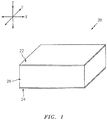
FIG. 1 is a partial, perspective block diagram illustration of an acoustic panel for attenuating noise. -
FIG. 2 is a sectional illustration of a portion of the acoustic panel taken in an x-z plane. -
FIG. 3 is another sectional illustration of the acoustic panel portion ofFIG. 2 taken in a y-z plane. -
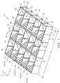
FIG. 4 is a perspective illustration of a portion of a cellular core for the acoustic panel. -
FIG. 5 is a perspective illustration of an enlarged portion of the cellular core ofFIG. 4 . -
FIG. 6 is a sectional illustration of a vertical stiffener included in the acoustic panel ofFIGS. 2 and 3 taken in the y-z plane. -
FIG. 7 is another sectional illustration of the vertical stiffener taken in the x-z plane. -
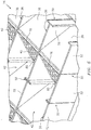
FIG. 8 is a sectional illustration of a portion of the acoustic panel bending in the x-z plane. -
FIG. 9 is a cross-sectional illustration of a top portion of a vertical stiffener included in the acoustic panel ofFIG. 8 . -
FIG. 10 is a cross-sectional illustration of a bottom portion of the vertical stiffener included in the acoustic panel ofFIG. 8 . -
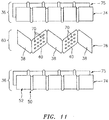
FIG. 11 is an exploded, perspective illustration of a cellular core for an acoustic panel before being assembled. -
FIGS. 12 and 13 are partial, perspective illustrations of another cellular core for the acoustic panel. -
FIGS. 14 and 15 are partial, perspective illustrations of another cellular core for the acoustic panel. -
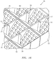
FIG. 16 is a partial, perspective illustration of still another cellular core for the acoustic panel. -
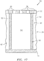
FIG. 17 is a partial, sectional illustration of another acoustic panel. -
FIG. 1 is a partial, perspective block diagram illustration of a structural,acoustic panel 20 for attenuating noise. Thisacoustic panel 20 may be configured to attenuate noise generated by an aircraft propulsion system such as, for example, a turbofan propulsion system or a turbojet propulsion system. With such a configuration, theacoustic panel 20 may be configured with a nacelle of the propulsion system. Theacoustic panel 20, for example, may be configured as or with an inner or outer barrel, a translating sleeve, a blocker door, etc. Alternatively, theacoustic panel 20 may be configured with another component / structure of the aircraft such as its fuselage or a wing. Furthermore, theacoustic panel 20 may be configured to also or alternatively attenuate aircraft related noise other than that generated by the propulsion system. Theacoustic panel 20 of the present disclosure, however, may alternatively be configured for non-aircraft applications. - The
acoustic panel 20 extends longitudinally along an x-axis. Theacoustic panel 20 extends laterally along a y-axis. Theacoustic panel 20 extends vertically along a z-axis. Note, the term "vertical" is used herein to describe a depthwise panel direction and is not limited to a gravitational up/down direction. Furthermore, for ease of illustration, the x-y plane is shown as a generally flat plane. However, in other embodiments, the x-y plane and, thus, theacoustic panel 20 may be curved and/or follow an undulating geometry. For example, the x-y plane and, thus, theacoustic panel 20 may be arcuate, cylindrical, conical, or tapered with or without radial undulations. In such embodiments, a solely vertical direction (e.g., z-axis) direction is defined relative to a position of interest on the x-y plane. For example, on a spherical x-y plane, the vertical direction (e.g., z-axis) direction is a radial direction. - The
acoustic panel 20 includes a perforated first (e.g., face)skin 22, a solid, non-perforated second (e.g., back)skin 24 and a structural,cellular core 26. Briefly, thecellular core 26 is disposed and extends vertically between thefirst skin 22 and thesecond skin 24. Thecellular core 26 is also connected to thefirst skin 22 and thesecond skin 24. Thecellular core 26, for example, may be welded, brazed, fused, adhered or otherwise bonded to thefirst skin 22 and/or thesecond skin 24. Thecellular core 26 may also or alternatively be mechanically fastened to thefirst skin 22 and/or thesecond skin 24. Alternatively, thecellular core 26 may be formed integral with thefirst skin 22 and/or thesecond skin 24 as a monolithic body using, for example, additive manufacturing. An exemplary, non-limiting embodiment of manufacturing an embodiment of theacoustic panel 20 is discussed below in further detail. However, as indicated above, the present disclosure is not limited to any particular manufacturing methods. - The
first skin 22 may be configured as a relatively thin sheet or layer of material that extends laterally and longitudinally along the x-y plane. This first skin material may include, but is not limited to, a metal, a polymer, a fiber reinforced matrix (e.g., fiberglass composite, carbon fiber composite, aramid fiber composite, etc.), or a combination thereof. Referring now toFIG. 2 , thefirst skin 22 has avertical thickness 28, which extends vertically between opposing side surfaces. Thefirst skin 22 includes a plurality ofperforations 30; e.g., apertures such as through-holes. Each of theseperforations 30 extends generally vertically through thefirst skin 22 between its side surfaces. - The
second skin 24 may be configured as a relatively thin sheet or layer of (e.g., continuous and uninterrupted) material that extends laterally and longitudinally along the x-y plane (seeFIG. 1 ). This second skin material may include, but is not limited to, a metal, a polymer, a fiber reinforced composite (e.g., fiberglass composite, carbon fiber composite, aramid fiber composite, etc.), or a combination thereof. The second skin material may be the same as or different than the first skin material. Thesecond skin 24 has avertical thickness 32, which extends vertically between opposing side surfaces. Thisvertical thickness 32 may be substantially equal to or different (e.g., greater or less) than thevertical thickness 28 of thefirst skin 22. - The
cellular core 26 extends laterally and longitudinally along the x-y plane (seeFIG. 1 ). Thecellular core 26 has avertical thickness 34, which extends vertically between opposing core sides, which are abutted against theskins vertical thickness 34 may be substantially greater than thevertical thickness first skin 22 and/or thesecond skin 24. Thevertical thickness 34, for example, may be at least ten to forty times (10-40x), or more, greater than thevertical thickness acoustic panel 20 of the present disclosure is not limited to such an exemplary embodiment. - Referring to
FIGS. 2-5 , thecellular core 26 includes a plurality ofwalls 36, a plurality ofbaffles 38 and a plurality ofseptums 40. Thesecomponents cellular core 26 as an open cavity (e.g., open cell) structure. This open cavity structure forms a plurality ofcavities 42 vertically between thefirst skin 22 and thesecond skin 24. Thesecavities 42 may be arranged in a plurality of linear arrays 44 (seeFIG. 4 ), where each array 44 extends longitudinally along the x-axis. Each of thecavities 42 may be fluidly coupled with one or morerespective perforations 30 in the first skin 22 (seeFIGS. 2 and 3 ). - The
walls 36 may be arranged generally parallel with one another. Thewalls 36 are laterally spaced from one another so as to respectively form thecavities 42 laterally between thewalls 36. Each of thewalls 36 thereby respectively forms lateral peripheral sides of thecavities 42 in at least one of the arrays 44. Each intermediate wall 36 (e.g., a wall laterally disposed between two other walls), more particularly, forms the lateral peripheral sides of thecavities 42 in a respective adjacent pair of the arrays 44. Eachintermediate wall 36 is also disposed laterally between the respective adjacent pair of the arrays 44 and thereby fluidly separates thecavities 42 in those arrays 44 from one another. - Each of the
walls 36 extends vertically between thefirst skin 22 and the second skin 24 (seeFIGS. 2 and 3 ). Each of thewalls 36 may also be connected (e.g., bonded and/or otherwise) to thefirst skin 22 and/or thesecond skin 24. Each of thewalls 36 is orientated substantially perpendicular to thefirst skin 22 and thesecond skin 24. However, in other embodiments, one or more of thewalls 36 may be offset from thefirst skin 22 and/or thesecond skin 24 by a non-ninety degree angle; e.g., an acute included angle. - Referring to
FIG. 4 , each of thewalls 36 has alength 46 that extends longitudinally along the x-axis. Each of thewalls 36 has athickness 48 that extends laterally along the y-axis, where thelength 46 is substantially (e.g., at least 20 times) larger than thethickness 48. The present disclosure, however, is not limited to the foregoing size relationship between thelength 46 andthickness 48 of thewalls 36. - The
thickness 48 of each of thewalls 36 changes as thatwall 36 extends longitudinally within theacoustic panel 20. Each of thewalls 36 ofFIG. 4 , for example, includes a plurality ofvertical stiffeners 50 interdisposed (e.g., alternated) with a plurality ofwebs 52. Each of thestiffeners 50 may be, for example, 1.5 to 10 times thicker than thewebs 52. The present disclosure, however, is not limited to the foregoing exemplary size relationship between the thickness of thevertical stiffeners 50 and thewebs 52. - Each of the
vertical stiffeners 50 may be configured as a structural flange portion, which is operable to increase the structural rigidity and strength of thewall 36. Thevertical stiffeners 50, for example, may increase vertical strength and, thus, resistance to buckling due to increased lateral stiffness. Thevertical stiffeners 50 may also increase lateral strength by increasing resistance to lateral bending. - Each of the
vertical stiffeners 50 ofFIG. 4 may be configured similar to a flange portion of a structural I-beam. More particularly, each of thevertical stiffeners 50 ofFIG. 4 projects laterally out from an adjacent pair of thewebs 52 in a first lateral direction and partially into a respective one of thecavities 42 to a distal end of thatstiffener 50. Each of thevertical stiffeners 50 also projects laterally out from the adjacent pair of thewebs 52 in a second (opposite) lateral direction and partially into another respective one of thecavities 42 to an opposing distal end of thatstiffener 50. However, in other embodiments, one or more of thevertical stiffeners 50 may only project laterally in one of the directions. -
FIGS. 6 and 7 illustrate an exemplary one of thevertical stiffeners 50. Thisvertical stiffener 50 extends vertically between thefirst skin 22 and thesecond skin 24. Thevertical stiffener 50 may also be connected (e.g., bonded and/or otherwise) to thefirst skin 22 and/or thesecond skin 24. Of course, in other embodiments, thevertical stiffener 50 may only engage and/or be connected to one of theskins vertical stiffener 50 may extend partially vertically within thewall 36 and not engage or be connected to either of theskins stiffener 50 is shown inFIGS. 6 and 7 as being perpendicular to theskins stiffeners 50 may alternatively be configured acutely or obtusely angled to theskins 22 and/or 24. - Referring again to
FIGS. 6 and 7 , thevertical stiffener 50 may be at least partially or completely vertically hollow. Thevertical stiffener 50 ofFIGS. 6 and 7 , for example, includes abore 54 which extends vertically through thatstiffener 50 to theskins bore 54 may extend vertically within or into (not through) thevertical stiffener 50. Thevertical stiffener 50 ofFIGS. 6 and 7 has a laterally elongated, generally rectangular cross-sectional (x-y plane) geometry; best seen inFIG. 5 . Thebore 54 has a corresponding laterally elongated, generally linear cross-sectional (x-y plane) geometry. - With the foregoing configuration, the
vertical stiffener 50 is configured to enable vertical bending of thewall 36. The term "vertical bending" may describe bending of a wall along its longitudinal length in, for example, the x-z plane. For example, as illustrated inFIGS. 8 and 9 , atop portion 56 of thevertical stiffener 50 may deform (e.g., into a square shape; seeFIG. 9 ) allowing theadjacent webs 52 to move longitudinally away from one another. In addition or alternatively, as illustrated inFIGS. 8 and 10 , abottom portion 58 of thevertical stiffener 50 may deform (e.g., pinch together; seeFIG. 10 ) allowing theadjacent webs 52 to move longitudinally towards one another. Thus, thevertical stiffener 50 may operate as a hinge or an accordion bellow. In this manner, theacoustic panel 20 may be formed with a generally curved sectional geometry as shown inFIG. 8 . Note, the terms "top" and "bottom" are used above to describe portions of the stiffener as situated in the drawings and are not intended to limit thevertical stiffener 50 or theacoustic panel 20 to such an exemplary gravitational orientation. - Each
vertical stiffener 50 is also operable to increase the surface area of thecellular core 26 that is next to and vertically engages thefirst skin 22 and thesecond skin 24. By increasing the surface area (compared to a wall without a stiffener or stiffeners), more area is available for connecting (e.g., bonding and/or otherwise) thecellular core 26 to thefirst skin 22 and thesecond skin 24. In this manner, theacoustic panel 20 can withstand higher shear forces than an acoustic panel of the same kind configured without such vertical stiffeners. - Referring again to
FIG. 4 , thevertical stiffeners 50 are interdisposed with thewebs 52 of acorresponding wall 36. More particularly, each of the vertical stiffeners 50 (unless configured at a longitudinal end of the wall 36) is disposed longitudinally between and connected to a respective adjacent pair of thewebs 52. Thus,adjacent stiffeners 50 are separated by a longitudinal distance. Similarly, each of the webs 52 (unless configured at a longitudinal end of the wall 36) extends longitudinally between and is connected to a respective adjacent pair of thevertical stiffeners 50. - The
baffles 38 and theseptums 40 are grouped together into a plurality of linear, longitudinally extendingarrays 60. Each of thesearrays 60 includes a subset (e.g., linear array) of thebaffles 38 and a subset (e.g., linear array) of theseptums 40. Thebaffles 38 in eacharray 60 are interdisposed with theseptums 40 in thatarray 60. More particularly, each of the baffles 38 (unless configured at a longitudinal end of the wall 36) is disposed and may extend longitudinally between a respective adjacent pair of theseptums 40. Similarly, each of the septums 40 (unless configured at a longitudinal end of the wall 36) is disposed and may extend longitudinally between a respective adjacent pair of thebaffles 38. - Referring to
FIG. 2 , one end 62 of each of thebaffles 38 is disposed towards, vertically engaged with and/or connected to thefirst skin 22. An opposing end 64 of each of thebaffles 38 is disposed towards, vertically engaged with and/or connected to thesecond skin 24. Thus, each of thebaffles 38 may be angularly offset from thefirst skin 22 and thesecond skin 24 by an angle; e.g., an acute angle or other (e.g., ninety degree) angle. Similarly, one end 66 of each of theseptums 40 is disposed towards, vertically engaged with and/or connected to thefirst skin 22. An opposing end 68 of each of theseptums 40 is disposed towards, vertically engaged with and/or connected to thesecond skin 24. Thus, each of theseptums 40 may be angularly offset from thefirst skin 22 and thesecond skin 24 by an angle; e.g., an acute angle or other (e.g., ninety degree) angle. In this manner, each array 60 (seeFIG. 4 ) ofbaffles 38 andseptums 40 ofFIG. 4 has a corrugated configuration, where one of thebaffles 38 and one of theseptums 40 may form a single corrugation. Of course, in other embodiments, one or more of the corrugations may each include an additional element (e.g., a bridge) and/or a slight gap. - Each of the
cavities 42 extends longitudinally between and is formed by an adjacent pair of thebaffles 38. Eachseptum 40 is disposed within and divides a respective one of thecavities 42 into fluidly coupled sub-cavities 42A and 42B. More particularly, one ormore perforations 70 in theseptum 40 fluidly coupled the sub-cavities 42A and 42B together. - With the foregoing
core 26 configuration, each of thecavities 42 forms a resonance chamber. Alength 72 of the resonance chamber extends diagonally between thefirst skin 22 and thesecond skin 24 and through a respective one of theseptums 40. Thelength 72 of the resonance chamber therefore is longer than thevertical thickness 34 of thecellular core 26. This enables noise attenuation of relatively low frequency noise without increasing thevertical thickness 34 of theacoustic panel 20. For example, each resonance chamber may receive noise waves through theperforations 30 in thefirst skin 22. The resonance chamber may reverse the phase of one or more frequencies of those sound waves using known acoustic reflection principles and subsequently direct the reverse phase sound waves out of theacoustic panel 20 through theperforations 30 to destructively interfere with other incoming noise waves. - The
cellular core 26 may be constructed from any suitable material(s). Thecellular core 26, for example, may be constructed from a metal, a polymer, a fiber reinforced composite (e.g., fiberglass composite, carbon fiber composite, aramid fiber composite, etc.), or a combination thereof. One or more of components of thecellular core 26 may be constructed from the same or a like material. Alternatively, one or more of the components of thecellular core 26 may be constructed from a different material than one or more of the other components of thecellular core 26. - In some embodiments, referring to
FIG. 11 , thecellular core 26 may be constructed from a plurality of strips 74-76 of bent and worked material; e.g., metal. Each of thewalls 36, for example, may be constructed from twostrips vertical stiffeners 50 may be formed by kinking or otherwise bending and deforming select portions of each of thestrips array 60 of thebaffles 38 and theseptums 40 may be constructed by forming theperforations 70 in select portions of astrip 76 of material. Thatperforated strip 76 of material may then be bent or otherwise deformed to provide thestrip 76 with a corrugated configuration. The formed strips 74-76 of material may then be assembled together to form thecellular core 26. - The
core 26 of the present disclosure may have various alternative configurations than those described above. For example, one or more of theseptums 40 may be configured generally perpendicular to thefirst skin 22 and/or thesecond skin 24. One or more of thevertical stiffeners 50 may each have a vertically uniform configuration as shown inFIG. 5 ; see alsoFIGS. 12, 13 and16 . One or more of thevertical stiffeners 50 may each have a vertically non-uniform (e.g., tapering) configuration as illustrated inFIGS. 14 and 15 . Thevertical stiffeners 50 may be respectively disposed longitudinally at (e.g., on, adjacent or proximate)intersections 78 and/or 80 between thebaffles 38 and theseptums 40 as shown inFIG. 5 ; see alsoFIGS. 12-16 . Alternatively, one or more of thestiffeners 50 may be respectively disposed longitudinally between theintersections baffles 38 and theseptums 40. One or more of thevertical stiffeners 50 may each have a hexagonal cross-sectional geometry (seeFIGS. 12 and 13 ), a square cross-sectional geometry (seeFIGS. 14 and 15 ), a diamond cross-sectional geometry (seeFIG. 16 ), or any other type of polygonal and/or curved cross-sectional geometry. In some embodiments, thebores 54 of one or more of thevertical stiffeners 50 may be fluidly coupled with one or morerespective perforations 30 in thefirst skin 22 as shown inFIG. 17 . In this manner, thosebores 54 may be configured as higher frequency noise attenuation chambers. The present disclosure therefore is not limited to the specific cellular core configurations described above and illustrated in the drawings. - While various embodiments of the present invention have been disclosed, it will be apparent to those of ordinary skill in the art that many more embodiments and implementations are possible within the scope of the invention. For example, the present invention as described herein includes several aspects and embodiments that include particular features. Although these features may be described individually, it is within the scope of the present invention that some or all of these features may be combined with any one of the aspects and remain within the scope of the invention. Accordingly, the present invention is not to be restricted except in light of the attached claims and their equivalents.
Claims (15)
- A structural panel (20), comprising:a first skin (22);a second skin (24); anda core (26) forming a plurality of cavities (42) vertically between the first skin (22) and the second skin (24), the core (26) including a wall (36) connected to and extending vertically between the first skin (22) and the second skin (24), the wall (36) laterally between and fluidly separating at least a first of the cavities (42) from a second of the cavities (42);wherein the wall (36) includes a vertical stiffener (50), and one or more perforations (30) in the first skin (22) are fluidly coupled with the first of the cavities (42).
- The panel of claim 1, wherein the vertical stiffener (50) is one of a plurality of vertical stiffeners (50) included with the wall (36), and one of the vertical stiffeners (50) is disposed a longitudinal distance along the wall (36) from an adjacent one of the vertical stiffeners (50).
- The panel of claim 1 or 2, wherein the vertical stiffener (50) projects laterally partially into the first and/or the second of the cavities (42).
- The panel of any preceding claim, wherein the vertical stiffener (50) is hollow and includes a bore (54) extending at least vertically within the vertical stiffener (50), wherein, optionally, one or more perforations (30) in the first skin (22) are fluidly coupled with the bore (54).
- The panel of any preceding claim, wherein the vertical stiffener (50) extends vertically to the first skin (22) and/or the second skin (24), wherein, optionally, the vertical stiffener (50) is connected to the first skin (22) and/or the second skin (24).
- The panel of any preceding claim, wherein the vertical stiffener (50) is configured to enable vertical bending of the wall (36), and/or wherein the vertical stiffener (50) is configured as an accordion bellow.
- The panel of any preceding claim, wherein
the wall (36) is a first wall (36) and the vertical stiffener (50) is a first vertical stiffener (50);
the core (26) includes a second wall (36) connected to and extending vertically between the first skin (22) and the second skin (24);
the second wall (36) is laterally between and fluidly separates at least the first of the cavities (42) from a third of the cavities (42); and
the second wall (36) includes a second vertical stiffener (50). - The panel of claim 7, wherein
the core (26) includes a plurality of baffles (38) and a plurality of septums (40);
the baffles (38) are arranged in a longitudinal linear array (60), each of the baffles (38) is connected to and extends laterally between the first wall (36) and the second wall (36), and the first of the cavities (42) extends longitudinally between an adjacent pair of the baffles (38); and
the septums (40) are arranged in a longitudinal linear array (60), each of the septums (40) is connected to and extends laterally between the first wall (36) and the second wall (36), a first of the septums (40) is disposed between the adjacent pair of the baffles (38) and divides the first of the cavities (42) into fluidly coupled first and second sub-cavities (42A, 42B), wherein, optionally, the first of the septums (40) is connected to and extends between the adjacent pair of the baffles (38). - The panel of claim 8, wherein the baffles (38) are arranged with the septums (40) together in a corrugated configuration.
- The panel of claim 8 or 9, wherein the vertical stiffener (50) is at an intersection (78, 80) between the first of the septums (40) and one of the adjacent pair of the baffles (38).
- The panel of claim 8 or 9, wherein
the vertical stiffener (50) is a first vertical stiffener (50) and the wall (36) further includes a second vertical stiffener (50); and
the first vertical stiffener (50) is at an intersection (78, 80) between the first of the septums (40) and a first of the adjacent pair of the baffles (38), and the second vertical stiffener (50) is at an intersection (80, 78) between the first of the septums (40) and a second of the adjacent pair of the baffles (38). - The panel of any preceding claim, wherein
the vertical stiffener (50) is one of a plurality of vertical stiffeners (50) included with the wall (36);
each of the vertical stiffeners (50) is configured as a structural flange portion; and
the wall (36) further includes a plurality of webs (52), where each of the webs (52) extends longitudinally between an adjacent pair of the vertical stiffeners (50). - The panel of any preceding claim, wherein the panel is configured as a component of an aircraft propulsion system.
- A structural panel (20) for attenuating noise, comprising:a first skin (22);a second skin (24); anda core (26) forming a plurality of cavities (42) vertically between the first skin (22) and the second skin (24), the core (26) including a plurality of walls (36) connected to and extending vertically between the first skin (22) and the second skin (24), a first of the walls (36) laterally between and fluidly separating at least a first of the cavities (42) from a second of the cavities (42), and a second of the walls (36) laterally between and fluidly separating at least the first of the cavities (42) from a third of the cavities (42);wherein each of the walls (36) includes a vertical stiffener (50), and the vertical stiffener (50) of the first of the walls (36) projects partially laterally into the first of the cavities (42); and
wherein one or more perforations (30) in the first skin (22) are fluidly coupled with the first of the cavities (42). - A structural panel (20) for attenuating noise, comprising:a first skin (22);a second skin (24); anda core (26) forming a plurality of cavities (42) vertically between the first skin (22) and the second skin (24), the core (26) including a plurality of walls (36), an array (60) of baffles (38) and an array (60) of septums (40), a first of the walls (36) laterally between and fluidly separating at least a first of the cavities (42) from a second of the cavities (42), and a second of the walls (36) laterally between and fluidly separating at least the first of the cavities (42) from a third of the cavities (42);wherein the baffles (38) are interdisposed with the septums (40) in a corrugated configuration, the first of the cavities (42) extends between an adjacent pair of the baffles (38), and a first of the septums (40) is disposed between the adjacent pair of the baffles (38) and divides the first of the cavities (42) into fluidly coupled first and second sub-cavities (42A, 42B);
wherein the first of the walls (36) includes a plurality of vertical stiffeners (50) distributed along a longitudinal length of the first of the walls (36); and
wherein one or more perforations (30) in the first skin (22) are fluidly coupled with the first of the cavities (42).
Applications Claiming Priority (1)
| Application Number | Priority Date | Filing Date | Title |
|---|---|---|---|
| US15/040,663 US9764818B2 (en) | 2016-02-10 | 2016-02-10 | Structural, cellular core with corrugated support walls |
Publications (3)
| Publication Number | Publication Date |
|---|---|
| EP3205574A2 true EP3205574A2 (en) | 2017-08-16 |
| EP3205574A3 EP3205574A3 (en) | 2017-11-22 |
| EP3205574B1 EP3205574B1 (en) | 2019-08-07 |
Family
ID=58043879
Family Applications (1)
| Application Number | Title | Priority Date | Filing Date |
|---|---|---|---|
| EP17155552.7A Active EP3205574B1 (en) | 2016-02-10 | 2017-02-10 | Structural, cellular core with corrugated support walls |
Country Status (2)
| Country | Link |
|---|---|
| US (1) | US9764818B2 (en) |
| EP (1) | EP3205574B1 (en) |
Cited By (4)
| Publication number | Priority date | Publication date | Assignee | Title |
|---|---|---|---|---|
| EP3364407A1 (en) * | 2017-02-14 | 2018-08-22 | Rohr, Inc. | Method for forming a structural panel |
| EP3447760A1 (en) * | 2017-08-22 | 2019-02-27 | Rohr, Inc. | Method for forming a structural panel |
| EP3553771A1 (en) * | 2018-04-03 | 2019-10-16 | Rohr, Inc. | Structured panel with structural reinforcement(s) |
| EP3964440A1 (en) * | 2020-09-04 | 2022-03-09 | The Boeing Company | Propulsion flow path duct systems and methods |
Families Citing this family (24)
| Publication number | Priority date | Publication date | Assignee | Title |
|---|---|---|---|---|
| FR3041937B1 (en) * | 2015-10-05 | 2017-10-20 | Airbus Operations Sas | COMPARTMENTED STRUCTURE FOR THE ACOUSTIC TREATMENT AND DEFROSTING OF AN AIRCRAFT NACELLE AND AN AIRCRAFT NACELLE INCORPORATING THE SAID STRUCTURE |
| US11024278B1 (en) * | 2016-06-09 | 2021-06-01 | Hrl Laboratories, Llc | Acoustic absorber |
| JP6636471B2 (en) * | 2017-02-16 | 2020-01-29 | 株式会社ニフコ | Sound absorber and sound absorbing structure |
| US10836502B2 (en) * | 2017-12-15 | 2020-11-17 | The Boeing Company | Wave-shaped acoustic insert and core |
| US11433990B2 (en) * | 2018-07-09 | 2022-09-06 | Rohr, Inc. | Active laminar flow control system with composite panel |
| US11261786B2 (en) * | 2018-08-06 | 2022-03-01 | Rohr, Inc. | Continuous slanted cell septum |
| US11359577B2 (en) * | 2018-08-22 | 2022-06-14 | Rohr, Inc. | Multi-degree of freedom acoustic panel |
| US11174815B2 (en) | 2018-09-14 | 2021-11-16 | Rohr, Inc. | Inlet deep cavity flutter liner |
| FR3088848B1 (en) * | 2018-11-28 | 2020-12-04 | Airbus Operations Sas | A method of manufacturing an acoustic element of a sound absorption structure from at least one sheet of material |
| FR3089567B1 (en) * | 2018-12-07 | 2020-11-20 | Safran Nacelles | Thrust reverser fitted with a lightweight thrust reverser flap |
| US11398214B2 (en) | 2018-12-14 | 2022-07-26 | Rohr, Inc. | Forming a structured panel with one or more structural reinforcements |
| US11242822B2 (en) * | 2018-12-14 | 2022-02-08 | Rohr, Inc. | Structured panel with multi-panel structure(s) |
| US11572850B2 (en) * | 2019-06-04 | 2023-02-07 | Rohr, Inc. | Acoustic panel with one or more structural stiffeners |
| CN112509544B (en) * | 2020-11-06 | 2024-12-06 | 国能水务环保有限公司 | A lightweight metal low-frequency noise reduction structure |
| US11715450B2 (en) | 2020-12-22 | 2023-08-01 | Rohr, Inc. | Acoustic panel core cell with funnel shaped septum |
| US11965465B2 (en) | 2020-12-22 | 2024-04-23 | Rohr, Inc. | Acoustic panel with multiple layer corrugated core |
| US11869472B2 (en) | 2021-08-02 | 2024-01-09 | Rohr, Inc. | Acoustic panel with reconfigurable chamber constrictions |
| US11993388B2 (en) | 2021-09-02 | 2024-05-28 | Rohr, Inc. | Corrugated stiffening devices utilizing peaks and valleys and methods of manufacture |
| US12014712B2 (en) | 2021-09-02 | 2024-06-18 | Rohr, Inc. | Corrugated acoustic stiffening devices and methods |
| US11780179B2 (en) | 2021-09-02 | 2023-10-10 | Rohr, Inc. | Thermoplastic composite panel with corrugated peaks and troughs stiffening systems and methods |
| EP4206448B1 (en) | 2022-01-04 | 2025-07-09 | Rohr, Inc. | Multi-core acoustic panel for an aircraft propulsion system |
| US12163472B2 (en) | 2022-09-02 | 2024-12-10 | Rohr, Inc. | Engine exhaust nozzle with acoustic attenuation |
| US20250214713A1 (en) * | 2023-12-27 | 2025-07-03 | Rohr, Inc. | Acoustic panel for an aircraft propulsion system |
| US20250214712A1 (en) * | 2023-12-27 | 2025-07-03 | Rohr, Inc. | Acoustic panel for an aircraft propulsion system |
Family Cites Families (51)
| Publication number | Priority date | Publication date | Assignee | Title |
|---|---|---|---|---|
| US2333343A (en) * | 1937-04-22 | 1943-11-02 | Armzen Company | Method of making structural materials |
| US2848132A (en) * | 1950-01-26 | 1958-08-19 | Davous Leon | Packing means |
| US3341395A (en) * | 1962-12-03 | 1967-09-12 | Solar Reflection Room Corp | Lightweight structural panel |
| US3542152A (en) | 1968-04-08 | 1970-11-24 | Gen Electric | Sound suppression panel |
| US3639106A (en) | 1968-05-06 | 1972-02-01 | Burnley Engineering Products L | Acoustic panel |
| US3507355A (en) * | 1969-05-22 | 1970-04-21 | Rohr Corp | Multi-layer face material for sound absorptive duct lining material |
| US3734234A (en) | 1971-11-08 | 1973-05-22 | Lockheed Aircraft Corp | Sound absorption structure |
| FR2191025B1 (en) * | 1972-07-04 | 1975-03-07 | Aerospatiale | |
| GB1406844A (en) | 1972-09-01 | 1975-09-17 | Short Brothers & Harland Ltd | Sound absorbing panels |
| US3821999A (en) | 1972-09-05 | 1974-07-02 | Mc Donnell Douglas Corp | Acoustic liner |
| US3850261A (en) | 1973-03-01 | 1974-11-26 | Gen Electric | Wide band width single layer sound suppressing panel |
| US3910374A (en) | 1974-03-18 | 1975-10-07 | Rohr Industries Inc | Low frequency structural acoustic attenuator |
| US3948346A (en) | 1974-04-02 | 1976-04-06 | Mcdonnell Douglas Corporation | Multi-layered acoustic liner |
| US4189027A (en) | 1976-08-19 | 1980-02-19 | United Technologies Corporation | Sound suppressor liners |
| US4240519A (en) | 1979-07-02 | 1980-12-23 | United Technologies Corporation | Acoustical turbine engine tail pipe plug |
| US4541879A (en) | 1982-07-15 | 1985-09-17 | Rohr Industries, Inc. | Method of manufacture of noise suppression panel |
| US4743740A (en) | 1985-10-07 | 1988-05-10 | Rohr Industries, Inc. | Buried element deicer |
| US4859517A (en) * | 1987-03-16 | 1989-08-22 | Hexcel Corporation | Formable honeycomb panel |
| US5431980A (en) * | 1993-02-01 | 1995-07-11 | Mccarthy; Daniel J. | Formable cellular material with synclastic behavior |
| US5923003A (en) | 1996-09-09 | 1999-07-13 | Northrop Grumman Corporation | Extended reaction acoustic liner for jet engines and the like |
| US5927647A (en) | 1997-09-24 | 1999-07-27 | Rohr, Inc. | Blocker door frame pressure structure for translating cowl of cascade thrust reverser for aircraft jet engine |
| US5997985A (en) | 1998-09-10 | 1999-12-07 | Northrop Grumman Corporation | Method of forming acoustic attenuation chambers using laser processing of multi-layered polymer films |
| GB0223697D0 (en) | 2002-10-14 | 2002-11-20 | Rolls Royce Plc | Acoustic liner for gas turbine engineers |
| US6871725B2 (en) | 2003-02-21 | 2005-03-29 | Jeffrey Don Johnson | Honeycomb core acoustic unit with metallurgically secured deformable septum, and method of manufacture |
| US7588212B2 (en) | 2003-07-08 | 2009-09-15 | Rohr Inc. | Method and apparatus for noise abatement and ice protection of an aircraft engine nacelle inlet lip |
| CN100402179C (en) | 2003-11-20 | 2008-07-16 | 喀山航空工业科学研究院股份公开公司 | Method for producing plywood with meandering corrugated core |
| US20130266772A1 (en) | 2004-06-15 | 2013-10-10 | John S. Fujii | Three-dimensional wood fiber structural composites |
| US7784283B2 (en) | 2006-05-03 | 2010-08-31 | Rohr, Inc. | Sound-absorbing exhaust nozzle center plug |
| US20110100747A1 (en) | 2006-05-24 | 2011-05-05 | Airbus Operations Gmbh | Sandwich element for the sound-absorbing inner cladding of means of transport, especially for the sound-absorbing inner cladding of aircraft |
| RU2413654C2 (en) | 2006-05-24 | 2011-03-10 | Эйрбас Дойчланд Гмбх | Multilayer element for noise-absorbing inner lining of transport facility, primarily, of aircraft |
| US7954224B2 (en) | 2006-08-18 | 2011-06-07 | Rohr, Inc. | Method of joining composite honeycomb sections |
| FR2912833B1 (en) | 2007-02-20 | 2009-08-21 | Airbus France Sas | PANEL FOR ACOUSTIC TREATMENT |
| FR2915522A1 (en) | 2007-04-30 | 2008-10-31 | Airbus France Sas | Acoustic attenuation panel i.e. acoustic attenuation lining, for propulsion system of aircraft, has cellular structure whose one of characteristics varies acoustic wave to locally oppose acoustic wave to impedance variations |
| FR2922152B1 (en) | 2007-10-16 | 2009-11-20 | Aircelle Sa | ALVEOLAR STRUCTURE FOR ACOUSTIC PANEL |
| FR2925463B1 (en) | 2007-12-21 | 2010-04-23 | Airbus France | STRUCTURE FOR ACOUSTIC TREATMENT MORE PARTICULARLY ADAPTED TO AIR INTAKE OF AN AIRCRAFT NACELLE |
| FR2930764B1 (en) | 2008-04-30 | 2010-05-07 | Airbus France | INTERCALE WAVE MOUNTING PANEL BETWEEN A MOTORIZATION AND A AIR INTAKE OF AN AIRCRAFT NACELLE |
| US7959109B2 (en) | 2008-07-02 | 2011-06-14 | The Boeing Company | Dual valve apparatus for aircraft engine ice protection and related methods |
| DE102008051241B4 (en) | 2008-10-10 | 2011-06-16 | Airbus Operations Gmbh | Muffler for an auxiliary engine of an aircraft |
| US8025122B2 (en) | 2008-11-06 | 2011-09-27 | The Boeing Company | Acoustically treated exhaust centerbody for jet engines and associated methods |
| GB0820597D0 (en) | 2008-11-11 | 2008-12-17 | Rolls Royce Plc | A noise reduction device |
| FR2953058B1 (en) | 2009-11-23 | 2017-11-03 | Aircelle Sa | ACOUSTIC SKIN FOR AN ACOUSTIC PANEL OF AN AIRCRAFT NACELLE |
| DE102011008921A1 (en) | 2011-01-19 | 2012-07-19 | Rolls-Royce Deutschland Ltd & Co Kg | Gas turbine exhaust cone |
| EP2700068A4 (en) | 2011-04-20 | 2016-01-13 | Dresser Rand Co | Multi-degree of freedom resonator array |
| FR2979385A1 (en) | 2011-08-22 | 2013-03-01 | Snecma | ACOUSTIC INSULATION PANEL FOR TURBOMACHINE AND TURBOMACHINE COMPRISING SUCH A PANEL |
| FR2983835B1 (en) | 2011-12-13 | 2014-02-21 | Airbus Operations Sas | METHOD FOR PRODUCING A PANEL FOR ACOUSTIC TREATMENT |
| DE102012022713B3 (en) * | 2012-11-21 | 2014-02-13 | Diehl Aircabin Gmbh | Panel and method of making a panel |
| US20140349082A1 (en) | 2013-05-21 | 2014-11-27 | The Boeing Company | Folded Core Panel |
| US8820477B1 (en) | 2013-07-29 | 2014-09-02 | The Boeing Company | Acoustic panel |
| US9284726B2 (en) | 2014-04-04 | 2016-03-15 | The Boeing Company | Pyramid waffle core structure and method of fabrication |
| US9476359B2 (en) | 2014-04-11 | 2016-10-25 | Rohr, Inc. | Acoustic liner |
| CN104723616B (en) | 2015-03-17 | 2016-07-06 | 西安交通大学 | A kind of orthogonal ripple sandwich composite construction of lightweight and preparation method thereof |
-
2016
- 2016-02-10 US US15/040,663 patent/US9764818B2/en active Active
-
2017
- 2017-02-10 EP EP17155552.7A patent/EP3205574B1/en active Active
Non-Patent Citations (1)
| Title |
|---|
| None |
Cited By (5)
| Publication number | Priority date | Publication date | Assignee | Title |
|---|---|---|---|---|
| EP3364407A1 (en) * | 2017-02-14 | 2018-08-22 | Rohr, Inc. | Method for forming a structural panel |
| EP3447760A1 (en) * | 2017-08-22 | 2019-02-27 | Rohr, Inc. | Method for forming a structural panel |
| EP3553771A1 (en) * | 2018-04-03 | 2019-10-16 | Rohr, Inc. | Structured panel with structural reinforcement(s) |
| EP3964440A1 (en) * | 2020-09-04 | 2022-03-09 | The Boeing Company | Propulsion flow path duct systems and methods |
| US11767776B2 (en) | 2020-09-04 | 2023-09-26 | The Boeing Company | Propulsion flow path duct systems and methods |
Also Published As
| Publication number | Publication date |
|---|---|
| EP3205574B1 (en) | 2019-08-07 |
| US9764818B2 (en) | 2017-09-19 |
| EP3205574A3 (en) | 2017-11-22 |
| US20170225764A1 (en) | 2017-08-10 |
Similar Documents
| Publication | Publication Date | Title |
|---|---|---|
| EP3205574B1 (en) | Structural, cellular core with corrugated support walls | |
| EP3232435B1 (en) | Acoustic panel with corrugated baffles and septums | |
| EP3206203B1 (en) | Acoustic panel with angled corrugated core structures | |
| EP3324400B1 (en) | Acoustic panel with sidewall stringers | |
| EP3422342B1 (en) | Acoustic panel with folding chamber | |
| EP3324401B1 (en) | Acoustic panel with sidewall stringers | |
| US9978354B2 (en) | Acoustic panel with vertical stiffeners | |
| US9708930B2 (en) | Multi-degree of freedom acoustic panel | |
| EP3594936B1 (en) | Structured panel with integrated skin and sidewalls | |
| US11242822B2 (en) | Structured panel with multi-panel structure(s) | |
| EP3748627B1 (en) | Acoustic panel with one or more structural stiffeners | |
| US20190061276A1 (en) | Method for forming a structural panel | |
| US10676171B2 (en) | Structural panel with splice joint between adjacent core structures | |
| US20220199064A1 (en) | Acoustic panel core cell with funnel shaped septum | |
| US20240271572A1 (en) | Acoustic panel with multiple layer corrugated core | |
| US10906659B2 (en) | Structured panel with structural reinforcement(s) |
Legal Events
| Date | Code | Title | Description |
|---|---|---|---|
| PUAI | Public reference made under article 153(3) epc to a published international application that has entered the european phase |
Free format text: ORIGINAL CODE: 0009012 |
|
| STAA | Information on the status of an ep patent application or granted ep patent |
Free format text: STATUS: THE APPLICATION HAS BEEN PUBLISHED |
|
| AK | Designated contracting states |
Kind code of ref document: A2 Designated state(s): AL AT BE BG CH CY CZ DE DK EE ES FI FR GB GR HR HU IE IS IT LI LT LU LV MC MK MT NL NO PL PT RO RS SE SI SK SM TR |
|
| AX | Request for extension of the european patent |
Extension state: BA ME |
|
| PUAL | Search report despatched |
Free format text: ORIGINAL CODE: 0009013 |
|
| AK | Designated contracting states |
Kind code of ref document: A3 Designated state(s): AL AT BE BG CH CY CZ DE DK EE ES FI FR GB GR HR HU IE IS IT LI LT LU LV MC MK MT NL NO PL PT RO RS SE SI SK SM TR |
|
| AX | Request for extension of the european patent |
Extension state: BA ME |
|
| RIC1 | Information provided on ipc code assigned before grant |
Ipc: G10K 11/172 20060101ALI20171013BHEP Ipc: B64C 1/06 20060101ALI20171013BHEP Ipc: B64C 1/40 20060101AFI20171013BHEP |
|
| STAA | Information on the status of an ep patent application or granted ep patent |
Free format text: STATUS: REQUEST FOR EXAMINATION WAS MADE |
|
| 17P | Request for examination filed |
Effective date: 20180522 |
|
| RBV | Designated contracting states (corrected) |
Designated state(s): AL AT BE BG CH CY CZ DE DK EE ES FI FR GB GR HR HU IE IS IT LI LT LU LV MC MK MT NL NO PL PT RO RS SE SI SK SM TR |
|
| STAA | Information on the status of an ep patent application or granted ep patent |
Free format text: STATUS: EXAMINATION IS IN PROGRESS |
|
| 17Q | First examination report despatched |
Effective date: 20180810 |
|
| GRAP | Despatch of communication of intention to grant a patent |
Free format text: ORIGINAL CODE: EPIDOSNIGR1 |
|
| STAA | Information on the status of an ep patent application or granted ep patent |
Free format text: STATUS: GRANT OF PATENT IS INTENDED |
|
| INTG | Intention to grant announced |
Effective date: 20190219 |
|
| GRAS | Grant fee paid |
Free format text: ORIGINAL CODE: EPIDOSNIGR3 |
|
| GRAA | (expected) grant |
Free format text: ORIGINAL CODE: 0009210 |
|
| STAA | Information on the status of an ep patent application or granted ep patent |
Free format text: STATUS: THE PATENT HAS BEEN GRANTED |
|
| AK | Designated contracting states |
Kind code of ref document: B1 Designated state(s): AL AT BE BG CH CY CZ DE DK EE ES FI FR GB GR HR HU IE IS IT LI LT LU LV MC MK MT NL NO PL PT RO RS SE SI SK SM TR |
|
| REG | Reference to a national code |
Ref country code: GB Ref legal event code: FG4D |
|
| REG | Reference to a national code |
Ref country code: CH Ref legal event code: EP Ref country code: AT Ref legal event code: REF Ref document number: 1163447 Country of ref document: AT Kind code of ref document: T Effective date: 20190815 |
|
| REG | Reference to a national code |
Ref country code: DE Ref legal event code: R096 Ref document number: 602017005770 Country of ref document: DE |
|
| REG | Reference to a national code |
Ref country code: IE Ref legal event code: FG4D |
|
| REG | Reference to a national code |
Ref country code: NL Ref legal event code: MP Effective date: 20190807 |
|
| REG | Reference to a national code |
Ref country code: LT Ref legal event code: MG4D |
|
| PG25 | Lapsed in a contracting state [announced via postgrant information from national office to epo] |
Ref country code: FI Free format text: LAPSE BECAUSE OF FAILURE TO SUBMIT A TRANSLATION OF THE DESCRIPTION OR TO PAY THE FEE WITHIN THE PRESCRIBED TIME-LIMIT Effective date: 20190807 Ref country code: LT Free format text: LAPSE BECAUSE OF FAILURE TO SUBMIT A TRANSLATION OF THE DESCRIPTION OR TO PAY THE FEE WITHIN THE PRESCRIBED TIME-LIMIT Effective date: 20190807 Ref country code: HR Free format text: LAPSE BECAUSE OF FAILURE TO SUBMIT A TRANSLATION OF THE DESCRIPTION OR TO PAY THE FEE WITHIN THE PRESCRIBED TIME-LIMIT Effective date: 20190807 Ref country code: SE Free format text: LAPSE BECAUSE OF FAILURE TO SUBMIT A TRANSLATION OF THE DESCRIPTION OR TO PAY THE FEE WITHIN THE PRESCRIBED TIME-LIMIT Effective date: 20190807 Ref country code: PT Free format text: LAPSE BECAUSE OF FAILURE TO SUBMIT A TRANSLATION OF THE DESCRIPTION OR TO PAY THE FEE WITHIN THE PRESCRIBED TIME-LIMIT Effective date: 20191209 Ref country code: BG Free format text: LAPSE BECAUSE OF FAILURE TO SUBMIT A TRANSLATION OF THE DESCRIPTION OR TO PAY THE FEE WITHIN THE PRESCRIBED TIME-LIMIT Effective date: 20191107 Ref country code: NO Free format text: LAPSE BECAUSE OF FAILURE TO SUBMIT A TRANSLATION OF THE DESCRIPTION OR TO PAY THE FEE WITHIN THE PRESCRIBED TIME-LIMIT Effective date: 20191107 Ref country code: NL Free format text: LAPSE BECAUSE OF FAILURE TO SUBMIT A TRANSLATION OF THE DESCRIPTION OR TO PAY THE FEE WITHIN THE PRESCRIBED TIME-LIMIT Effective date: 20190807 |
|
| REG | Reference to a national code |
Ref country code: AT Ref legal event code: MK05 Ref document number: 1163447 Country of ref document: AT Kind code of ref document: T Effective date: 20190807 |
|
| PG25 | Lapsed in a contracting state [announced via postgrant information from national office to epo] |
Ref country code: ES Free format text: LAPSE BECAUSE OF FAILURE TO SUBMIT A TRANSLATION OF THE DESCRIPTION OR TO PAY THE FEE WITHIN THE PRESCRIBED TIME-LIMIT Effective date: 20190807 Ref country code: AL Free format text: LAPSE BECAUSE OF FAILURE TO SUBMIT A TRANSLATION OF THE DESCRIPTION OR TO PAY THE FEE WITHIN THE PRESCRIBED TIME-LIMIT Effective date: 20190807 Ref country code: LV Free format text: LAPSE BECAUSE OF FAILURE TO SUBMIT A TRANSLATION OF THE DESCRIPTION OR TO PAY THE FEE WITHIN THE PRESCRIBED TIME-LIMIT Effective date: 20190807 Ref country code: IS Free format text: LAPSE BECAUSE OF FAILURE TO SUBMIT A TRANSLATION OF THE DESCRIPTION OR TO PAY THE FEE WITHIN THE PRESCRIBED TIME-LIMIT Effective date: 20191207 Ref country code: RS Free format text: LAPSE BECAUSE OF FAILURE TO SUBMIT A TRANSLATION OF THE DESCRIPTION OR TO PAY THE FEE WITHIN THE PRESCRIBED TIME-LIMIT Effective date: 20190807 Ref country code: GR Free format text: LAPSE BECAUSE OF FAILURE TO SUBMIT A TRANSLATION OF THE DESCRIPTION OR TO PAY THE FEE WITHIN THE PRESCRIBED TIME-LIMIT Effective date: 20191108 |
|
| PG25 | Lapsed in a contracting state [announced via postgrant information from national office to epo] |
Ref country code: TR Free format text: LAPSE BECAUSE OF FAILURE TO SUBMIT A TRANSLATION OF THE DESCRIPTION OR TO PAY THE FEE WITHIN THE PRESCRIBED TIME-LIMIT Effective date: 20190807 |
|
| PG25 | Lapsed in a contracting state [announced via postgrant information from national office to epo] |
Ref country code: PL Free format text: LAPSE BECAUSE OF FAILURE TO SUBMIT A TRANSLATION OF THE DESCRIPTION OR TO PAY THE FEE WITHIN THE PRESCRIBED TIME-LIMIT Effective date: 20190807 Ref country code: EE Free format text: LAPSE BECAUSE OF FAILURE TO SUBMIT A TRANSLATION OF THE DESCRIPTION OR TO PAY THE FEE WITHIN THE PRESCRIBED TIME-LIMIT Effective date: 20190807 Ref country code: AT Free format text: LAPSE BECAUSE OF FAILURE TO SUBMIT A TRANSLATION OF THE DESCRIPTION OR TO PAY THE FEE WITHIN THE PRESCRIBED TIME-LIMIT Effective date: 20190807 Ref country code: RO Free format text: LAPSE BECAUSE OF FAILURE TO SUBMIT A TRANSLATION OF THE DESCRIPTION OR TO PAY THE FEE WITHIN THE PRESCRIBED TIME-LIMIT Effective date: 20190807 Ref country code: IT Free format text: LAPSE BECAUSE OF FAILURE TO SUBMIT A TRANSLATION OF THE DESCRIPTION OR TO PAY THE FEE WITHIN THE PRESCRIBED TIME-LIMIT Effective date: 20190807 Ref country code: DK Free format text: LAPSE BECAUSE OF FAILURE TO SUBMIT A TRANSLATION OF THE DESCRIPTION OR TO PAY THE FEE WITHIN THE PRESCRIBED TIME-LIMIT Effective date: 20190807 |
|
| PG25 | Lapsed in a contracting state [announced via postgrant information from national office to epo] |
Ref country code: IS Free format text: LAPSE BECAUSE OF FAILURE TO SUBMIT A TRANSLATION OF THE DESCRIPTION OR TO PAY THE FEE WITHIN THE PRESCRIBED TIME-LIMIT Effective date: 20200224 Ref country code: SK Free format text: LAPSE BECAUSE OF FAILURE TO SUBMIT A TRANSLATION OF THE DESCRIPTION OR TO PAY THE FEE WITHIN THE PRESCRIBED TIME-LIMIT Effective date: 20190807 Ref country code: SM Free format text: LAPSE BECAUSE OF FAILURE TO SUBMIT A TRANSLATION OF THE DESCRIPTION OR TO PAY THE FEE WITHIN THE PRESCRIBED TIME-LIMIT Effective date: 20190807 Ref country code: CZ Free format text: LAPSE BECAUSE OF FAILURE TO SUBMIT A TRANSLATION OF THE DESCRIPTION OR TO PAY THE FEE WITHIN THE PRESCRIBED TIME-LIMIT Effective date: 20190807 |
|
| REG | Reference to a national code |
Ref country code: DE Ref legal event code: R097 Ref document number: 602017005770 Country of ref document: DE |
|
| PLBE | No opposition filed within time limit |
Free format text: ORIGINAL CODE: 0009261 |
|
| STAA | Information on the status of an ep patent application or granted ep patent |
Free format text: STATUS: NO OPPOSITION FILED WITHIN TIME LIMIT |
|
| PG2D | Information on lapse in contracting state deleted |
Ref country code: IS |
|
| 26N | No opposition filed |
Effective date: 20200603 |
|
| PG25 | Lapsed in a contracting state [announced via postgrant information from national office to epo] |
Ref country code: SI Free format text: LAPSE BECAUSE OF FAILURE TO SUBMIT A TRANSLATION OF THE DESCRIPTION OR TO PAY THE FEE WITHIN THE PRESCRIBED TIME-LIMIT Effective date: 20190807 |
|
| REG | Reference to a national code |
Ref country code: CH Ref legal event code: PL |
|
| REG | Reference to a national code |
Ref country code: BE Ref legal event code: MM Effective date: 20200229 |
|
| PG25 | Lapsed in a contracting state [announced via postgrant information from national office to epo] |
Ref country code: MC Free format text: LAPSE BECAUSE OF FAILURE TO SUBMIT A TRANSLATION OF THE DESCRIPTION OR TO PAY THE FEE WITHIN THE PRESCRIBED TIME-LIMIT Effective date: 20190807 Ref country code: LU Free format text: LAPSE BECAUSE OF NON-PAYMENT OF DUE FEES Effective date: 20200210 |
|
| PG25 | Lapsed in a contracting state [announced via postgrant information from national office to epo] |
Ref country code: CH Free format text: LAPSE BECAUSE OF NON-PAYMENT OF DUE FEES Effective date: 20200229 Ref country code: LI Free format text: LAPSE BECAUSE OF NON-PAYMENT OF DUE FEES Effective date: 20200229 |
|
| PG25 | Lapsed in a contracting state [announced via postgrant information from national office to epo] |
Ref country code: IE Free format text: LAPSE BECAUSE OF NON-PAYMENT OF DUE FEES Effective date: 20200210 |
|
| PG25 | Lapsed in a contracting state [announced via postgrant information from national office to epo] |
Ref country code: BE Free format text: LAPSE BECAUSE OF NON-PAYMENT OF DUE FEES Effective date: 20200229 |
|
| PG25 | Lapsed in a contracting state [announced via postgrant information from national office to epo] |
Ref country code: MT Free format text: LAPSE BECAUSE OF FAILURE TO SUBMIT A TRANSLATION OF THE DESCRIPTION OR TO PAY THE FEE WITHIN THE PRESCRIBED TIME-LIMIT Effective date: 20190807 Ref country code: CY Free format text: LAPSE BECAUSE OF FAILURE TO SUBMIT A TRANSLATION OF THE DESCRIPTION OR TO PAY THE FEE WITHIN THE PRESCRIBED TIME-LIMIT Effective date: 20190807 |
|
| PG25 | Lapsed in a contracting state [announced via postgrant information from national office to epo] |
Ref country code: MK Free format text: LAPSE BECAUSE OF FAILURE TO SUBMIT A TRANSLATION OF THE DESCRIPTION OR TO PAY THE FEE WITHIN THE PRESCRIBED TIME-LIMIT Effective date: 20190807 |
|
| P01 | Opt-out of the competence of the unified patent court (upc) registered |
Free format text: CASE NUMBER: UPC_APP_0017253_3205574/2025 Effective date: 20251211 |
|
| PGFP | Annual fee paid to national office [announced via postgrant information from national office to epo] |
Ref country code: GB Payment date: 20260121 Year of fee payment: 10 |
|
| PGFP | Annual fee paid to national office [announced via postgrant information from national office to epo] |
Ref country code: DE Payment date: 20260121 Year of fee payment: 10 |
|
| PGFP | Annual fee paid to national office [announced via postgrant information from national office to epo] |
Ref country code: FR Payment date: 20260121 Year of fee payment: 10 |