EP3205558A2 - Steering system - Google Patents
Steering system Download PDFInfo
- Publication number
- EP3205558A2 EP3205558A2 EP17155276.3A EP17155276A EP3205558A2 EP 3205558 A2 EP3205558 A2 EP 3205558A2 EP 17155276 A EP17155276 A EP 17155276A EP 3205558 A2 EP3205558 A2 EP 3205558A2
- Authority
- EP
- European Patent Office
- Prior art keywords
- jacket
- buffer member
- support surface
- supported
- steering system
- Prior art date
- Legal status (The legal status is an assumption and is not a legal conclusion. Google has not performed a legal analysis and makes no representation as to the accuracy of the status listed.)
- Granted
Links
Images





Classifications
-
- B—PERFORMING OPERATIONS; TRANSPORTING
- B62—LAND VEHICLES FOR TRAVELLING OTHERWISE THAN ON RAILS
- B62D—MOTOR VEHICLES; TRAILERS
- B62D1/00—Steering controls, i.e. means for initiating a change of direction of the vehicle
- B62D1/02—Steering controls, i.e. means for initiating a change of direction of the vehicle vehicle-mounted
- B62D1/16—Steering columns
- B62D1/18—Steering columns yieldable or adjustable, e.g. tiltable
- B62D1/187—Steering columns yieldable or adjustable, e.g. tiltable with tilt adjustment; with tilt and axial adjustment
-
- B—PERFORMING OPERATIONS; TRANSPORTING
- B62—LAND VEHICLES FOR TRAVELLING OTHERWISE THAN ON RAILS
- B62D—MOTOR VEHICLES; TRAILERS
- B62D1/00—Steering controls, i.e. means for initiating a change of direction of the vehicle
- B62D1/02—Steering controls, i.e. means for initiating a change of direction of the vehicle vehicle-mounted
- B62D1/16—Steering columns
- B62D1/18—Steering columns yieldable or adjustable, e.g. tiltable
- B62D1/184—Mechanisms for locking columns at selected positions
-
- B—PERFORMING OPERATIONS; TRANSPORTING
- B62—LAND VEHICLES FOR TRAVELLING OTHERWISE THAN ON RAILS
- B62D—MOTOR VEHICLES; TRAILERS
- B62D1/00—Steering controls, i.e. means for initiating a change of direction of the vehicle
- B62D1/02—Steering controls, i.e. means for initiating a change of direction of the vehicle vehicle-mounted
- B62D1/16—Steering columns
- B62D1/18—Steering columns yieldable or adjustable, e.g. tiltable
- B62D1/185—Steering columns yieldable or adjustable, e.g. tiltable adjustable by axial displacement, e.g. telescopically
-
- B—PERFORMING OPERATIONS; TRANSPORTING
- B62—LAND VEHICLES FOR TRAVELLING OTHERWISE THAN ON RAILS
- B62D—MOTOR VEHICLES; TRAILERS
- B62D1/00—Steering controls, i.e. means for initiating a change of direction of the vehicle
- B62D1/02—Steering controls, i.e. means for initiating a change of direction of the vehicle vehicle-mounted
- B62D1/16—Steering columns
- B62D1/18—Steering columns yieldable or adjustable, e.g. tiltable
- B62D1/187—Steering columns yieldable or adjustable, e.g. tiltable with tilt adjustment; with tilt and axial adjustment
- B62D1/189—Steering columns yieldable or adjustable, e.g. tiltable with tilt adjustment; with tilt and axial adjustment the entire column being tiltable as a unit
-
- B—PERFORMING OPERATIONS; TRANSPORTING
- B62—LAND VEHICLES FOR TRAVELLING OTHERWISE THAN ON RAILS
- B62D—MOTOR VEHICLES; TRAILERS
- B62D1/00—Steering controls, i.e. means for initiating a change of direction of the vehicle
- B62D1/02—Steering controls, i.e. means for initiating a change of direction of the vehicle vehicle-mounted
- B62D1/16—Steering columns
- B62D1/18—Steering columns yieldable or adjustable, e.g. tiltable
- B62D1/19—Steering columns yieldable or adjustable, e.g. tiltable incorporating energy-absorbing arrangements, e.g. by being yieldable or collapsible
- B62D1/195—Yieldable supports for the steering column
Definitions
- the invention relates to a steering system.
- a buffer material is attached to one of a bolt shaft of a fastener that achieves telescopic lock and a stopper plate that faces the bolt shaft in an axial direction of a column pipe.
- a steering system is proposed (for example, see Japanese Patent Application Publication No. 2014-24493 ( JP 2014-24493 A )).
- the buffer material may be detached from the one of the bolt shaft and the stopper plate and thus cannot stably absorb the shock in the steering system described in JP 2014-24493 A .
- the invention provides a steering system in which a buffer member is unlikely to be detached and can stably absorb a shock at a time of contact.
- a first aspect of the invention relates to a steering system including a column jacket that includes a lower jacket, and an upper jacket having a tubular shape, the upper jacket being fitted into the lower jacket so as to be slidable with respect to the lower jacket in a column axis direction within a specified sliding range during telescopic adjustment, and the upper jacket moving integrally with a steering member in the column axis direction; an engagement member that is supported by the lower jacket; a retaining member that is fixed to an outer periphery of the upper jacket and moves integrally with the upper jacket during the telescopic adjustment; and a buffer member that is retained by the retaining member so as to face the engagement member in the column axis direction and contacts the engagement member in a contact direction at a time when the upper jacket is displaced to one sliding end of the specified sliding range.
- the retaining member includes a support surface that extends in the column axis direction, faces outward in a radial direction of the upper jacket, and supports the buffer member in the radial direction; paired holding portions that are respectively disposed on both sides of the buffer member in a circumferential direction of the upper jacket and hold the buffer member toward the support surface; and a restriction portion configured to be engaged with an end of the buffer member on a side toward which an opposite direction is directed, so as to restrict movement of the buffer member in the opposite direction, the opposite direction being opposite to the contact direction.
- the paired holding portions of the retaining member hold the buffer member toward the support surface. Accordingly, when the buffer member contacts the engagement member during the telescopic adjustment, the buffer member is unlikely to be detached from the retaining member and thus can stably absorb a shock at the time of contact.
- the restriction portion may include an inclined surface that is inclined toward a side toward which the contact direction is directed as the inclined surface extends outward in the radial direction.
- the buffer member may include a supported surface that is supported by the support surface; and the supported surface may include a protrusion that contacts the support surface and forms a space between the supported surface and the support surface.
- the buffer member when the buffer member contacts the engagement member, along with compressed deformation of the buffer member in the column axis direction, the supported surface of the buffer member is deformed and expanded such that a portion thereof is protruded in the space on the side of the support surface.
- deformation of the buffer member in a direction in which the buffer member separates from the support surface is suppressed.
- the buffer member is further unlikely to be detached from the retaining member.
- the buffer member may include a first surface that is a supported surface supported by the support surface, a second surface that is disposed on a side opposite to the first surface in the radial direction, and a rib that is formed on the second surface and extends in the column axis direction.
- the buffer member has high rigidity against bending toward the second surface-side that is a side opposite to the support surface. Accordingly, when the buffer member contacts the engagement member and is compressed in the column axis direction, bending deformation of the buffer member toward the second surface-side is suppressed. Thus, the buffer member is further unlikely to be detached from the retaining member.
- the steering system may include a restriction member that is supported by the lower jacket; and when the buffer member contacts the engagement member, the restriction member may be disposed on an opposite side of the buffer member from the support surface so as to restrict separation of the buffer member from the support surface.
- the separation of the buffer member from the support surface is suppressed by the restriction member that is supported by the lower jacket.
- the buffer member is further unlikely to be detached from the retaining member.
- FIG. 1 is a partially-fractured schematic side view that shows a schematic configuration of a steering system according to a first embodiment of the invention.
- a steering system 1 includes a steering shaft 2, a column jacket 3, an intermediate shaft 4, and a turning mechanism 5.
- an upper side in a column axis direction X as an axial direction of the steering shaft 2 will be referred to as an axially upper side XU
- a lower side in the column axis direction X will be referred to as an axially lower side XL.
- a steering member 6 such as a steering wheel is coupled to an end in the axially upper side XU of the steering shaft 2.
- the steering system 1 turns steered wheels (not shown) in accordance with steering of the steering member 6.
- the turning mechanism 5 is a rack and pinion mechanism, for example, but is not limited thereto.
- the steering shaft 2 includes a tubular upper shaft 2U and a lower shaft 2L.
- the upper shaft 2U and the lower shaft 2L are fitted to each other by spline fitting or serration fitting, for example, such that the upper shaft 2U and the lower shaft 2L slide relative to each other in the column axis direction X.
- the steering member 6 is coupled to the end in the axially upper side XU of the upper shaft 2U.
- the column jacket 3 includes a lower jacket 8 as an outer jacket and an upper jacket 7 having a tubular shape as an inner jacket that is fitted into the lower jacket 8.
- the column axis direction X is also an axial direction of the upper jacket 7 and an axial direction of the lower jacket 8.
- the steering shaft 2 is inserted through the column jacket 3.
- the upper shaft 2U is rotatably supported by the upper jacket 7 via a bearing 9, and the lower shaft 2L is rotatably supported by the lower jacket 8 via a bearing 10.
- the column jacket 3 can be extended and contracted together with the steering shaft 2 in the column axis direction X.
- a position of the steering member 6 can be adjusted in a longitudinal direction of a vehicle.
- the steering system 1 has a telescopic adjustment function.
- the upper jacket 7 can slide within a specified sliding range (corresponding to a telescopic adjustment range) in the column axis direction X with respect to the lower jacket 8.
- a specified sliding range corresponding to a telescopic adjustment range
- the column jacket 3 is in the most contracted state.
- the upper jacket 7 is located at an upper limit sliding position as the other end position of the sliding range, the column jacket 3 is in the most extended state.
- the lower limit sliding position will also be referred to as a telescopic short position
- the upper limit sliding position will also be referred to as a telescopic long position.
- the steering system 1 includes: a fixed bracket 14 that is fixed to a vehicle body 13; a tilt center shaft 15 that is supported by the fixed bracket 14; and a column bracket 16 that is fixed to an outer periphery of the lower jacket 8 and is rotatably supported by the tilt center shaft 15.
- the steering shaft 2 and the column jacket 3 can rotate in an up-down direction Y with a tilt center CC as a center axis of the tilt center shaft 15 serving as a fulcrum.
- the steering system 1 has a tilt adjusting function.
- the steering system 1 includes: a bracket 17 that is fixed to the vehicle body 13; and a fastening mechanism 18 that locks the position after tilt adjustment and the telescopic adjustment.
- the fastening mechanism 18 achieves locking by fastening paired fastened portions 19 via the bracket 17.
- the fastened portions 19 are integrally provided in an upper portion of the lower jacket 8 in the column axis direction X.
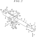
- FIG. 2 is a schematic perspective view of the steering system 1.
- the lower jacket 8 includes a slit 26 that extends from an upper end thereof in the column axis direction X toward the axially lower side XL thereof.
- the paired fastened portions 19 are respectively disposed on both sides of the slit 26.
- a diameter of the lower jacket 8 can be elastically reduced by fastening the paired fastened portions 19.
- FIG. 3 is a schematic sectional view of the steering system 1 and corresponds to a sectional view that is cut along line III-III in FIG. 1 .
- the bracket 17 includes: an attachment plate 24 that is attached to the vehicle body 13; and paired side plates 22 that respectively extend below in the up-down direction Y from both ends of the attachment plate 24.
- a long tilt hole 23 that extends in the up-down direction Y is formed in each of the side plates 22.
- the paired fastened portions 19 of the lower jacket 8 are disposed between the paired side plates 22 and each have a plate shape that extends along an inner surface 22b of the corresponding side plate 22.
- An insertion hole 29 as a circular hole is formed in each of the fastened portions 19.
- the steering system 1 includes an upper limit sliding position restriction mechanism 27 that restricts (defines) the upper limit sliding position of the upper jacket 7 during the telescopic adjustment.
- the upper limit sliding position restriction mechanism 27 includes: a guide groove 27a that is formed in the lower jacket 8 and extends in the column axis direction X; and a guided protrusion 27b that is fixed to the upper jacket 7 and is fitted to the guide groove 27a.
- the guide groove 27a restricts rotation of the upper jacket 7 via the guided protrusion 27b.
- the fastening mechanism 18 includes: an operation lever 20 as an operation member that is rotationally operated by a driver; and a fastening shaft 21 that is integrally rotatable with the operation lever 20.
- a center axis C1 of the fastening shaft 21 corresponds to rotation center of the operation lever 20.
- the fastening shaft 21 is a bolt and is inserted through the long tilt holes 23 of both of the side plates 22 of the bracket 17 and the insertion holes 29 of both of the fastened portions 19 of the lower jacket 8.
- the fastening shaft 21 and the lower jacket 8 integrally move in the up-down direction Y with respect to the bracket 17 during the tilt adjustment.
- a head 21a that is provided at an end of the fastening shaft 21 is fixed to the operation lever 20 so as to be rotatable integrally with the operation lever 20.
- the fastening mechanism 18 further includes a force conversion mechanism 30 that is interposed between the head 21a of the fastening shaft 21 and one of the side plates 22 (the side plate 22 on a left side in FIG. 3 ), and converts operation torque of the operation lever 20 to an axial force of the fastening shaft 21 (a fastening force for fastening the paired side plates 22).
- the force conversion mechanism 30 includes: a rotary cam 31 that is coupled to the operation lever 20 so as to be rotatable integrally with the operation lever 20 and whose movement in a fastening shaft direction J with respect to the fastening shaft 21 is restricted; and one fastening member 32 that is engaged with the rotary cam 31 and fastens the one side plate 22.
- the one fastening member 32 is a non-rotary cam whose rotation is restricted.
- the fastening mechanism 18 further includes: a nut 33 that is screwed to a screw 21b provided at the other end of the fastening shaft 21; another fastening member 34 that fastens the other side plate 22 (the side plate 22 on a right side in FIG. 3 ); and an interposition member 35 that is interposed between the other fastening member 34 and the nut 33.
- the interposition member 35 includes a washer 36 and a needle roller bearing 37.
- the rotary cam 31, the one fastening member 32, and the other fastening member 34 are supported on an outer periphery of the fastening shaft 21. Rotation of each of the one fastening member 32 and the other fastening member 34 is restricted by engagement with the corresponding long tilt hole 23.
- the fastening member 32 moves along the fastening shaft direction J in a direction in which the fastening member 32 moves away from the rotary cam 31. In this way, the paired side plates 22 of the bracket 17 are clamped and fastened by both of the fastening members 32, 34.
- each of the side plates 22 of the bracket 17 fastens the corresponding fastened portion 19 of the lower jacket 8.
- the diameter of the lower jacket 8 is elastically reduced, and the lower jacket 8 thereby fastens the upper jacket 7.
- movement of the upper jacket 7 in the column axis direction X is restricted, and telescopic lock is achieved.
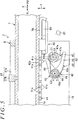
- FIG. 4 is a sectional view of a main portion of the steering system 1.
- the steering system 1 includes a tooth lock mechanism 40 in order to stabilize initial restriction thereof in a telescopic direction during a secondary collision of a vehicle collision.
- the tooth lock mechanism 40 has such a configuration that teeth thereof mesh each other, and thereby retains the telescopic position of the upper jacket 7.
- the tooth lock mechanism 40 includes: a first tooth member 41 that is fixed to an outer periphery 7a of the upper jacket 7; a second tooth member 42 that is rotatably supported by the lower jacket 8; and an interlocking mechanism 43 that causes the second tooth member 42 to rotate in accordance with the rotation of the fastening shaft 21.
- the first tooth member 41 includes a plurality of first teeth 41 a that are arranged at specified intervals in the column axis direction X.
- a plurality of grooves 41b may be formed at specified intervals so as to extend through a long plate, for example, and each of the plurality of first teeth 41a of the first tooth member 41 may be formed between two of the adjacent grooves 41b.
- the second tooth member 42 is rotatably supported by the paired fastened portions 19 of the lower jacket 8 via a support shaft 44.
- the second tooth member 42 includes a second tooth 42a that is engaged with/disengaged from the first tooth 41a along with rotation of the second tooth member 42 about the support shaft 44.
- both ends of the support shaft 44 in an axial direction are respectively supported by the paired fastened portions 19, and the second tooth member 42 is supported by the upper jacket 7 at an intermediate portion of the support shaft 44 in the axial direction.
- the second tooth member 42 includes: a boss 45 that surrounds an outer periphery of the support shaft 44; and a first arm 46 that extends so as to be protruded from an outer periphery of the boss 45.
- the second tooth 42a is formed at an extended end of the first arm 46.
- the support shaft 44 includes a fracture target portion (not shown) that is to be fractured by a shock during the secondary collision generated in a locked state where the first tooth 41a and the second tooth 42a mesh each other. Accordingly, a shock absorption load is generated by fracture of the fracture target portion during the secondary collision.
- movement of the upper jacket 7 to the axially lower side XL shock absorption movement
- the interlocking mechanism 43 incudes: a cam member 47 that is coupled to the fastening shaft 21 so as to be rotatable integrally with the fastening shaft 21; a second arm 48 as a cam follower member that is rotatable integrally with the second tooth member 42 and follows the cam member 47 (i.e., moves in accordance with the cam member 47); and an urging member 49 that rotationally urges the second tooth member 42 in a direction in which the second tooth 42a meshes with the first tooth 41a, via the second arm 48.
- the cam member 47 includes: a boss 47a that is fitted to the outer periphery of the fastening shaft 21 so as to be rotatable integrally with the fastening shaft 21; and a cam protrusion 47b that is protruded radially outward from the boss 47a.
- the urging member 49 is formed of a torsion spring, for example. More specifically, the urging member 49 includes: a coil portion 49a that surrounds the boss 45 of the second tooth member 42; a first engagement portion 49b that extends from the coil portion 49a and is engaged with the outer periphery of the fastening shaft 21; and a second engagement portion 49c that is engaged with the second arm 48 as the cam follower member.
- the urging member 49 rotationally urges the second tooth member 42 counterclockwise in FIG. 4 (indicated by a blank arrow in FIG. 4 ).
- FIG. 6 is a sectional view of the main portion of the steering system 1 and shows a state where the upper jacket 7 is displaced to the lower limit sliding position as the end position of the sliding range during the telescopic adjustment.
- the steering system 1 includes a lower limit sliding position restriction mechanism 60 that restricts (defines) the lower limit sliding position (the telescopic short position) of the upper jacket 7.
- the lower limit sliding position restriction mechanism 60 includes: the second tooth member 42 as an engagement member that is supported by the lower jacket 8; and a buffer member 80 that is retained by a retaining member 70 that moves integrally with the upper jacket 7 in the column axis direction X.
- FIG. 7 is an exploded perspective view of the retaining member 70 and the buffer member 80.
- FIG. 8 is a bottom view of the retaining member 70.
- FIG. 9A is a bottom view of the lower limit sliding position restriction mechanism 60
- FIG. 9B is a sectional view that is taken along line IXB-IXB in FIG. 9A .
- the retaining member 70 is formed integrally with the first tooth member 41 as a single member.
- the retaining member 70 extends from an upper end 41c of the first tooth member 41 to the axially upper side XU, the upper end 41c being an end in the axially upper side XU.
- the first tooth member 41 and the retaining member 70 may be made of sheet metal and may be integrally pressed.
- the retaining member 70 includes: a first portion 71 that is integrally coupled to the upper end 41c of the first tooth member 41; a second portion 72 that extends from the first portion 71 to the axially upper side XU; paired holding portions 73 that are provided in the first portion 71; and a restriction portion 74 that is provided in the second portion 72.
- the width of the second portion 72 in the circumferential direction P is set to be larger than that of the first portion 71.
- the second portion 72 protrudes toward both sides of the first portion 71.
- the retaining member 70 includes: an attached surface 70a that is attached along the outer periphery 7a of the upper jacket 7; and a support surface 70b that is opposite to the attached surface 70a in a radial direction R of the upper jacket 7.
- the attached surface 70a and the support surface 70b are provided in the first portion 71 and the second portion 72 of the retaining member 70.
- the attached surface 70a and the support surface 70b extend in the column axis direction X and the circumferential direction P of the upper jacket 7.
- the attached surface 70a faces inward in the radial direction R (hereinafter referred to as radial inward R1).
- the support surface 70b faces outward in the radial direction R (hereinafter referred to as radial outward R2) and supports the buffer member 80 in the radial direction R.
- the paired holding portions 73 are plate members, each of which extends in the column axis direction X, and extend from the first portion 71 so as to cross the first portion 71.
- the paired holding portions 73 are respectively disposed on both sides of the first portion 71 in the circumferential direction P of the upper jacket 7 and hold the buffer member 80 toward the support surface 70b.
- the paired holding portions 73 each include an inclined surface 73a that faces the support surface 70b.
- the inclined surface 73a may be a curved surface or a straight surface.
- the restriction portion 74 is provided at an end 72a in the axially upper side XU of the second portion 72.
- the restriction portion 74 receives the buffer member 80 in an opposite direction Z2 opposite to the contact direction Z1, so as to restrict movement of the buffer member 80 in the opposite direction Z2.
- the restriction portion 74 includes an inclined surface 74a that is inclined toward a side toward which the contact direction Z1 is directed as the inclined surface 74a extends in the radial outward R2 of the upper jacket 7. As shown in FIG. 6 , FIG. 7 , FIG. 9A, and FIG.
- the buffer member 80 includes a first portion 81, a second portion 82, a first surface 80a, a second surface 80b, an end 80c on the contact direction Z1-side (i.e., on the side toward which the contact direction Z1 is directed), the other end 80d on the opposite direction Z2-side (i.e., on a side toward which the opposite direction Z2 is directed), protrusions 83, and a rib 84.
- the first portion 81 is held toward the support surface 70b by the paired holding portions 73 of the retaining member 70, and is supported in the radial direction R by the first portion 71 of the retaining member 70.
- the second portion 82 extends toward the axially upper side XU (i.e., the side toward which the opposite direction Z2 is directed, the opposite direction Z2 being opposite to the contact direction Z1) of the first portion 81 and is supported in the radial direction R by the second portion 72 of the retaining member 70.
- the width in the circumferential direction P of the upper jacket 7 the width of the second portion 82 in the circumferential direction P is set to be larger than that of the first portion 81.
- the second portion 82 protrudes toward both sides of the first portion 81 in the circumferential direction P.
- Protruding portions of the second portion 82 which protrude from the first portion 81, are disposed on the opposite direction Z2-side of the paired holding portions 73 (i.e., on the side of the paired holding portions 73 in the opposite direction Z2).
- the paired holding portions 73 are respectively engaged with the protruding portions of the second portion 82 in the column axis direction X.
- the buffer member 80 is restricted from being separated from the retaining member 70 toward the contact direction Z1-side.
- the first surface 80a of the buffer member 80 is a supported surface that faces the support surface 70b of the retaining member 70 and that is supported by the support surface 70b.
- the first surface 80a (the supported surface) is formed as a curved surface that is curved in the circumferential direction P of the upper jacket 7, and extends in the column axis direction X.
- the first surface 80a faces the radial inward R1.
- the second surface 80b is disposed on a side opposite to the first surface 80a in the radial direction R.
- the first surface 80a is provided with the plurality of protrusions 83 that contact the support surface 70b and form a space S between the support surface 70b and the first surface 80a.
- One or some of the protrusions 83 may be elongated protrusions, each of which extends across the first portion 81 and the second portion 82 in the column axis direction X, and the rest of the protrusions may be elongated protrusions, each of which is disposed only in the second portion 82 and extends in the column axis direction X.
- the second surface 80b is provided with the rib 84 that extends in the column axis direction X.
- the rib 84 extends across the first portion 81 and the second portion 82 in the column axis direction X.
- the end 80c of the buffer member 80 is located on the contact direction Z1-side of the paired holding portions 73 of the retaining member 70 (i.e., on the side of the paired holding portions 73 in the contact direction Z1), and contacts the second tooth 42a of the second tooth member 42 (the engagement member) at the lower limit sliding position during the telescopic adjustment.
- the other end 80d of the buffer member 80 is engaged with the inclined surface 74a of the restriction portion 74 in the retaining member 70.
- the other end 80d includes an inclined surface that is inclined in a reverse direction as compared to the inclination of the inclined surface 74a, so as to follow the inclined surface 74a (in other words, the other end 80d includes an inclined surface that is inclined toward the side toward which the opposite direction Z2 is directed as the inclined surface extends toward the radial inward R1).
- the first portion 81 of the buffer member 80 includes paired side surfaces 81 a that are provided on the opposite sides thereof in the circumferential direction P. As shown in FIG. 9B , each of the paired side surfaces 81a is inclined such that the inclination of the side surface 81a coincides with the inclination of the inclined surface 73a of the corresponding holding portion 73.
- the first portion 81 of the buffer member 80 When the buffer member 80 is assembled to the retaining member 70 during assembly, the first portion 81 of the buffer member 80 may be pressed toward the radial inward R1, so as to be fitted between the paired holding portions 73 as shown in FIG. 7 .
- the first portion 81 may be inserted between the paired holding portions 73 toward the axially lower side XL.
- the paired holding portions 73 of the retaining member 70 hold the buffer member 80 toward the support surface 70b of the retaining member 70.
- the buffer member 80 contacts the second tooth member 42 as the engagement member during the telescopic adjustment, the buffer member 80 is unlikely to be detached from the retaining member 70 and thus can stably absorb the shock at the time of contact.
- the buffer member 80 contacts the second tooth member 42, separation of the buffer member 80 from the support surface 70b (separation to the radial outward R2) is suppressed by the inclined surface 74a of the restriction portion 74 in the retaining member 70.
- the buffer member 80 is further unlikely to be detached from the retaining member 70.
- the protrusions 83 each of which is formed on the first surface 80a as the supported surface, form the space S between the first surface 80a and the support surface 70b.
- the buffer member 80 when the buffer member 80 contacts the second tooth member 42 during the telescopic adjustment, along with compressed deformation of the buffer member 80 in the column axis direction X, the first surface 80a of the buffer member 80 is deformed and expanded such that a portion thereof is protruded in the space S on the side of the support surface 70b.
- the deformation of the buffer member 80 in a direction in which the buffer member 80 separates (moves away) from the support surface 70b is suppressed.
- the buffer member 80 is further unlikely to be detached from the retaining member 70.
- the rib 84 that extends in the column axis direction X is formed on the second surface 80b of the buffer member 80, and the buffer member 80 thereby has high rigidity against bending toward the second surface 80b-side (indicated by a blank arrow in FIG. 6 ). Accordingly, when the buffer member 80 contacts the second tooth member 42 and is compressed in the column axis direction X during the telescopic adjustment, the bending deformation of the buffer member 80 toward the second surface 80b-side is suppressed. Thus, the buffer member 80 is further unlikely to be detached from the retaining member 70.
- the cam member 47 that is supported by the lower jacket 8 is disposed on the opposite side of the buffer member 80 from the support surface 70b of the retaining member 70, and the cam member 47 functions as a restriction member that restricts the separation of the buffer member 80 from the support surface 70b.
- the buffer member 80 is further unlikely to be detached from the retaining member 70.
- the retaining member 70 may be provided as a separate component from the first tooth member 41 and may be fixed to the upper jacket 7.
- the retaining member 70 may be formed integrally with the upper jacket 7 by using a single material.
- the tooth lock mechanism 40 may not be provided.
- a shaft member such as a bolt that is fixed to the lower jacket 8, may be used.
- a shaft member or a tubular member that is supported by the lower jacket 8 may be used as the restriction member.
- Various modifications can be made to the embodiment within the scope of the invention.
Landscapes
- Engineering & Computer Science (AREA)
- Chemical & Material Sciences (AREA)
- Combustion & Propulsion (AREA)
- Transportation (AREA)
- Mechanical Engineering (AREA)
- Steering Controls (AREA)
Abstract
Description
- The invention relates to a steering system.
- In a steering system, a buffer material is attached to one of a bolt shaft of a fastener that achieves telescopic lock and a stopper plate that faces the bolt shaft in an axial direction of a column pipe. When the buffer material contacts the other of the bolt shaft and the stopper plate during telescopic adjustment, an adjustment range of the telescopic adjustment is restricted. Such a steering system is proposed (for example, see
Japanese Patent Application Publication No. 2014-24493 JP 2014-24493 A - In the case where a large shock is generated at a time when the buffer material contacts the other of the bolt shaft and the stopper plate, the buffer material may be detached from the one of the bolt shaft and the stopper plate and thus cannot stably absorb the shock in the steering system described in
JP 2014-24493 A - The invention provides a steering system in which a buffer member is unlikely to be detached and can stably absorb a shock at a time of contact.
- A first aspect of the invention relates to a steering system including a column jacket that includes a lower jacket, and an upper jacket having a tubular shape, the upper jacket being fitted into the lower jacket so as to be slidable with respect to the lower jacket in a column axis direction within a specified sliding range during telescopic adjustment, and the upper jacket moving integrally with a steering member in the column axis direction; an engagement member that is supported by the lower jacket; a retaining member that is fixed to an outer periphery of the upper jacket and moves integrally with the upper jacket during the telescopic adjustment; and a buffer member that is retained by the retaining member so as to face the engagement member in the column axis direction and contacts the engagement member in a contact direction at a time when the upper jacket is displaced to one sliding end of the specified sliding range. The retaining member includes a support surface that extends in the column axis direction, faces outward in a radial direction of the upper jacket, and supports the buffer member in the radial direction; paired holding portions that are respectively disposed on both sides of the buffer member in a circumferential direction of the upper jacket and hold the buffer member toward the support surface; and a restriction portion configured to be engaged with an end of the buffer member on a side toward which an opposite direction is directed, so as to restrict movement of the buffer member in the opposite direction, the opposite direction being opposite to the contact direction.
- In the above aspect, the paired holding portions of the retaining member hold the buffer member toward the support surface. Accordingly, when the buffer member contacts the engagement member during the telescopic adjustment, the buffer member is unlikely to be detached from the retaining member and thus can stably absorb a shock at the time of contact.
- In the above aspect, the restriction portion may include an inclined surface that is inclined toward a side toward which the contact direction is directed as the inclined surface extends outward in the radial direction.
- In the above configuration, when the buffer member contacts the engagement member, separation of the buffer member from the support surface is suppressed by the inclined surface of the restriction portion of the retaining member. Thus, the buffer member is further unlikely to be detached from the retaining member.
- In the above aspect, the buffer member may include a supported surface that is supported by the support surface; and the supported surface may include a protrusion that contacts the support surface and forms a space between the supported surface and the support surface.
- In the above configuration, when the buffer member contacts the engagement member, along with compressed deformation of the buffer member in the column axis direction, the supported surface of the buffer member is deformed and expanded such that a portion thereof is protruded in the space on the side of the support surface. Thus, deformation of the buffer member in a direction in which the buffer member separates from the support surface is suppressed. Thus, the buffer member is further unlikely to be detached from the retaining member.
- In the above aspect, the buffer member may include a first surface that is a supported surface supported by the support surface, a second surface that is disposed on a side opposite to the first surface in the radial direction, and a rib that is formed on the second surface and extends in the column axis direction.
- In the above configuration, the buffer member has high rigidity against bending toward the second surface-side that is a side opposite to the support surface. Accordingly, when the buffer member contacts the engagement member and is compressed in the column axis direction, bending deformation of the buffer member toward the second surface-side is suppressed. Thus, the buffer member is further unlikely to be detached from the retaining member.
- In the above aspect, the steering system may include a restriction member that is supported by the lower jacket; and when the buffer member contacts the engagement member, the restriction member may be disposed on an opposite side of the buffer member from the support surface so as to restrict separation of the buffer member from the support surface.
- In the above configuration, the separation of the buffer member from the support surface is suppressed by the restriction member that is supported by the lower jacket. Thus, the buffer member is further unlikely to be detached from the retaining member.
- Features, advantages, and technical and industrial significance of exemplary embodiments of the invention will be described below with reference to the accompanying drawings, in which like numerals denote like elements, and wherein:
-
FIG. 1 is a partially-fractured schematic side view of a steering system according to one embodiment of the invention; -
FIG. 2 is a schematic perspective view of the steering system; -
FIG. 3 is a sectional view of a main portion of the steering system and corresponds to a sectional view that is taken along line III-III inFIG. 1 ; -
FIG. 4 is a sectional view of the main portion of the steering system and shows a locked state of a tooth lock mechanism; -
FIG. 5 is a sectional view of the main portion of the steering system and shows an unlocked state of the tooth lock mechanism; -
FIG. 6 is a sectional view of the main portion of the steering system and shows a state where an upper jacket is displaced to a lower limit sliding position as an end position of a sliding range during telescopic adjustment; -
FIG. 7 is an exploded perspective view of a lower limit sliding position restriction mechanism that restricts the lower limit sliding position of the upper jacket; -
FIG. 8 is a bottom view of a retaining member that is integrally provided with a first tooth member; and -
FIG. 9A is a bottom view of the lower limit sliding position restriction mechanism, andFIG. 9B is a sectional view that is taken along line IXB-IXB inFIG. 9A . - A description will hereinafter be made on an embodiment of the invention in accordance with the drawings.
FIG. 1 is a partially-fractured schematic side view that shows a schematic configuration of a steering system according to a first embodiment of the invention. With reference toFIG. 1 , asteering system 1 includes asteering shaft 2, acolumn jacket 3, an intermediate shaft 4, and aturning mechanism 5. Hereinafter, an upper side in a column axis direction X as an axial direction of thesteering shaft 2 will be referred to as an axially upper side XU, and a lower side in the column axis direction X will be referred to as an axially lower side XL. - A
steering member 6 such as a steering wheel is coupled to an end in the axially upper side XU of thesteering shaft 2. Thesteering system 1 turns steered wheels (not shown) in accordance with steering of thesteering member 6. Theturning mechanism 5 is a rack and pinion mechanism, for example, but is not limited thereto. Thesteering shaft 2 includes a tubularupper shaft 2U and alower shaft 2L. Theupper shaft 2U and thelower shaft 2L are fitted to each other by spline fitting or serration fitting, for example, such that theupper shaft 2U and thelower shaft 2L slide relative to each other in the column axis direction X. Thesteering member 6 is coupled to the end in the axially upper side XU of theupper shaft 2U. - The
column jacket 3 includes alower jacket 8 as an outer jacket and anupper jacket 7 having a tubular shape as an inner jacket that is fitted into thelower jacket 8. The column axis direction X is also an axial direction of theupper jacket 7 and an axial direction of thelower jacket 8. Thesteering shaft 2 is inserted through thecolumn jacket 3. Theupper shaft 2U is rotatably supported by theupper jacket 7 via abearing 9, and thelower shaft 2L is rotatably supported by thelower jacket 8 via abearing 10. - When the
upper shaft 2U slides in the column axis direction X with respect to thelower shaft 2L, thecolumn jacket 3 can be extended and contracted together with thesteering shaft 2 in the column axis direction X. By extending and contracting thesteering shaft 2 and thecolumn jacket 3 in the column axis direction X, a position of thesteering member 6 can be adjusted in a longitudinal direction of a vehicle. Thus, thesteering system 1 has a telescopic adjustment function. - During telescopic adjustment, the
upper jacket 7 can slide within a specified sliding range (corresponding to a telescopic adjustment range) in the column axis direction X with respect to thelower jacket 8. When theupper jacket 7 is located at a lower limit sliding position as an end position of the sliding range, thecolumn jacket 3 is in the most contracted state. When theupper jacket 7 is located at an upper limit sliding position as the other end position of the sliding range, thecolumn jacket 3 is in the most extended state. The lower limit sliding position will also be referred to as a telescopic short position, and the upper limit sliding position will also be referred to as a telescopic long position. - The
steering system 1 includes: a fixedbracket 14 that is fixed to avehicle body 13; atilt center shaft 15 that is supported by the fixedbracket 14; and acolumn bracket 16 that is fixed to an outer periphery of thelower jacket 8 and is rotatably supported by thetilt center shaft 15. The steeringshaft 2 and thecolumn jacket 3 can rotate in an up-down direction Y with a tilt center CC as a center axis of thetilt center shaft 15 serving as a fulcrum. - When the
steering shaft 2 and thecolumn jacket 3 rotate about the tilt center CC, a position of the steeringmember 6 can be adjusted in the up-down direction Y (a height direction). Thus, thesteering system 1 has a tilt adjusting function. Thesteering system 1 includes: abracket 17 that is fixed to thevehicle body 13; and afastening mechanism 18 that locks the position after tilt adjustment and the telescopic adjustment. Thefastening mechanism 18 achieves locking by fastening paired fastenedportions 19 via thebracket 17. The fastenedportions 19 are integrally provided in an upper portion of thelower jacket 8 in the column axis direction X. -
FIG. 2 is a schematic perspective view of thesteering system 1. As shown inFIG. 2 , thelower jacket 8 includes aslit 26 that extends from an upper end thereof in the column axis direction X toward the axially lower side XL thereof. The paired fastenedportions 19 are respectively disposed on both sides of theslit 26. A diameter of thelower jacket 8 can be elastically reduced by fastening the paired fastenedportions 19.FIG. 3 is a schematic sectional view of thesteering system 1 and corresponds to a sectional view that is cut along line III-III inFIG. 1 . - As shown in
FIG. 3 , thebracket 17 includes: anattachment plate 24 that is attached to thevehicle body 13; and pairedside plates 22 that respectively extend below in the up-down direction Y from both ends of theattachment plate 24. Along tilt hole 23 that extends in the up-down direction Y is formed in each of theside plates 22. The paired fastenedportions 19 of thelower jacket 8 are disposed between the pairedside plates 22 and each have a plate shape that extends along aninner surface 22b of thecorresponding side plate 22. Aninsertion hole 29 as a circular hole is formed in each of the fastenedportions 19. - The
steering system 1 includes an upper limit slidingposition restriction mechanism 27 that restricts (defines) the upper limit sliding position of theupper jacket 7 during the telescopic adjustment. The upper limit slidingposition restriction mechanism 27 includes: aguide groove 27a that is formed in thelower jacket 8 and extends in the column axis direction X; and a guidedprotrusion 27b that is fixed to theupper jacket 7 and is fitted to theguide groove 27a. Theguide groove 27a restricts rotation of theupper jacket 7 via the guidedprotrusion 27b. - In addition, an end (not shown) in the axially upper side XU of the
guide groove 27a contacts the guidedprotrusion 27b during the telescopic adjustment. In this way, movement of theupper jacket 7 is restricted at the upper limit sliding position (the telescopic long position) of the sliding range. Thus, removal of theupper jacket 7 from thelower jacket 8 is also prevented. As shown inFIG. 1 andFIG. 2 , thefastening mechanism 18 includes: anoperation lever 20 as an operation member that is rotationally operated by a driver; and afastening shaft 21 that is integrally rotatable with theoperation lever 20. A center axis C1 of thefastening shaft 21 corresponds to rotation center of theoperation lever 20. - The
fastening shaft 21 is a bolt and is inserted through the long tilt holes 23 of both of theside plates 22 of thebracket 17 and the insertion holes 29 of both of the fastenedportions 19 of thelower jacket 8. Thefastening shaft 21 and thelower jacket 8 integrally move in the up-down direction Y with respect to thebracket 17 during the tilt adjustment. As shown inFIG. 3 , ahead 21a that is provided at an end of thefastening shaft 21 is fixed to theoperation lever 20 so as to be rotatable integrally with theoperation lever 20. Thefastening mechanism 18 further includes aforce conversion mechanism 30 that is interposed between thehead 21a of thefastening shaft 21 and one of the side plates 22 (theside plate 22 on a left side inFIG. 3 ), and converts operation torque of theoperation lever 20 to an axial force of the fastening shaft 21 (a fastening force for fastening the paired side plates 22). - The
force conversion mechanism 30 includes: arotary cam 31 that is coupled to theoperation lever 20 so as to be rotatable integrally with theoperation lever 20 and whose movement in a fastening shaft direction J with respect to thefastening shaft 21 is restricted; and onefastening member 32 that is engaged with therotary cam 31 and fastens the oneside plate 22. The onefastening member 32 is a non-rotary cam whose rotation is restricted. Thefastening mechanism 18 further includes: anut 33 that is screwed to ascrew 21b provided at the other end of thefastening shaft 21; anotherfastening member 34 that fastens the other side plate 22 (theside plate 22 on a right side inFIG. 3 ); and aninterposition member 35 that is interposed between theother fastening member 34 and thenut 33. Theinterposition member 35 includes awasher 36 and aneedle roller bearing 37. - The
rotary cam 31, the onefastening member 32, and theother fastening member 34 are supported on an outer periphery of thefastening shaft 21. Rotation of each of the onefastening member 32 and theother fastening member 34 is restricted by engagement with the correspondinglong tilt hole 23. When therotary cam 31 rotates with respect to the onefastening member 32 along with rotation of theoperation lever 20 in a locking direction, thefastening member 32 moves along the fastening shaft direction J in a direction in which thefastening member 32 moves away from therotary cam 31. In this way, the pairedside plates 22 of thebracket 17 are clamped and fastened by both of thefastening members - At this time, each of the
side plates 22 of thebracket 17 fastens the corresponding fastenedportion 19 of thelower jacket 8. In this way, movement of thelower jacket 8 in the up-down direction Y is restricted, and tilt lock is achieved. In addition, when both of the fastenedportions 19 are fastened, the diameter of thelower jacket 8 is elastically reduced, and thelower jacket 8 thereby fastens theupper jacket 7. As a result, movement of theupper jacket 7 in the column axis direction X is restricted, and telescopic lock is achieved. - On the other hand, when the
operation lever 20 rotates in an unlocking direction, thefastening member 32 moves along the fastening shaft direction J in a direction in which thefastening member 32 approaches therotary cam 31, along with rotation of therotary cam 31. In this way, fastening of the pairedside plates 22 by both of thefastening members FIG. 4 is a sectional view of a main portion of thesteering system 1. As shown inFIG. 1 andFIG. 4 , thesteering system 1 includes atooth lock mechanism 40 in order to stabilize initial restriction thereof in a telescopic direction during a secondary collision of a vehicle collision. Thetooth lock mechanism 40 has such a configuration that teeth thereof mesh each other, and thereby retains the telescopic position of theupper jacket 7. - The
tooth lock mechanism 40 includes: afirst tooth member 41 that is fixed to anouter periphery 7a of theupper jacket 7; asecond tooth member 42 that is rotatably supported by thelower jacket 8; and aninterlocking mechanism 43 that causes thesecond tooth member 42 to rotate in accordance with the rotation of thefastening shaft 21. Thefirst tooth member 41 includes a plurality offirst teeth 41 a that are arranged at specified intervals in the column axis direction X. A plurality ofgrooves 41b may be formed at specified intervals so as to extend through a long plate, for example, and each of the plurality offirst teeth 41a of thefirst tooth member 41 may be formed between two of theadjacent grooves 41b. - The
second tooth member 42 is rotatably supported by the paired fastenedportions 19 of thelower jacket 8 via asupport shaft 44. Thesecond tooth member 42 includes asecond tooth 42a that is engaged with/disengaged from thefirst tooth 41a along with rotation of thesecond tooth member 42 about thesupport shaft 44. Although not shown, both ends of thesupport shaft 44 in an axial direction are respectively supported by the paired fastenedportions 19, and thesecond tooth member 42 is supported by theupper jacket 7 at an intermediate portion of thesupport shaft 44 in the axial direction. - The
second tooth member 42 includes: aboss 45 that surrounds an outer periphery of thesupport shaft 44; and afirst arm 46 that extends so as to be protruded from an outer periphery of theboss 45. Thesecond tooth 42a is formed at an extended end of thefirst arm 46. Thesupport shaft 44 includes a fracture target portion (not shown) that is to be fractured by a shock during the secondary collision generated in a locked state where thefirst tooth 41a and thesecond tooth 42a mesh each other. Accordingly, a shock absorption load is generated by fracture of the fracture target portion during the secondary collision. In addition, due to the fracture, movement of theupper jacket 7 to the axially lower side XL (shock absorption movement) is allowed. - The interlocking
mechanism 43 incudes: acam member 47 that is coupled to thefastening shaft 21 so as to be rotatable integrally with thefastening shaft 21; asecond arm 48 as a cam follower member that is rotatable integrally with thesecond tooth member 42 and follows the cam member 47 (i.e., moves in accordance with the cam member 47); and an urgingmember 49 that rotationally urges thesecond tooth member 42 in a direction in which thesecond tooth 42a meshes with thefirst tooth 41a, via thesecond arm 48. Thecam member 47 includes: aboss 47a that is fitted to the outer periphery of thefastening shaft 21 so as to be rotatable integrally with thefastening shaft 21; and acam protrusion 47b that is protruded radially outward from theboss 47a. - The urging
member 49 is formed of a torsion spring, for example. More specifically, the urgingmember 49 includes: acoil portion 49a that surrounds theboss 45 of thesecond tooth member 42; afirst engagement portion 49b that extends from thecoil portion 49a and is engaged with the outer periphery of thefastening shaft 21; and asecond engagement portion 49c that is engaged with thesecond arm 48 as the cam follower member. The urgingmember 49 rotationally urges thesecond tooth member 42 counterclockwise inFIG. 4 (indicated by a blank arrow inFIG. 4 ). - When the
operation lever 20 and thefastening shaft 21 rotate about the center axis C1 of thefastening shaft 21 in the locking direction (clockwise inFIG. 5 ) from an unlocked state shown inFIG. 5 , thecam protrusion 47b allows counterclockwise rotation of thesecond arm 48 about a center axis C2 of thesupport shaft 44. Accordingly, with an action of the urgingmember 49, thesecond tooth member 42 rotates counterclockwise, and thesecond tooth 42a meshes with thefirst tooth 41a as shown inFIG. 4 . In this way, tooth lock is achieved. - When the
operation lever 20 rotates in the unlocking direction (counterclockwise inFIG. 4 ) from the locked state shown inFIG. 4 , as shown inFIG. 5 , thecam protrusion 47b causes thesecond tooth member 42 to rotate clockwise about the center axis C2 via thesecond arm 48 against the urgingmember 49. Accordingly, meshing of thesecond tooth 42a with thefirst tooth 41a is cancelled, and the tooth lock is thereby cancelled. -
FIG. 6 is a sectional view of the main portion of thesteering system 1 and shows a state where theupper jacket 7 is displaced to the lower limit sliding position as the end position of the sliding range during the telescopic adjustment. As shown inFIG. 6 , thesteering system 1 includes a lower limit slidingposition restriction mechanism 60 that restricts (defines) the lower limit sliding position (the telescopic short position) of theupper jacket 7. The lower limit slidingposition restriction mechanism 60 includes: thesecond tooth member 42 as an engagement member that is supported by thelower jacket 8; and abuffer member 80 that is retained by a retainingmember 70 that moves integrally with theupper jacket 7 in the column axis direction X. - When the
upper jacket 7 is displaced to the lower limit sliding position, thebuffer member 80 functions as a buffer stopper that restricts the lower limit sliding position while contacting thesecond tooth 42a of thesecond tooth member 42 in a contact direction Z1 to buffer a shock.FIG. 7 is an exploded perspective view of the retainingmember 70 and thebuffer member 80.FIG. 8 is a bottom view of the retainingmember 70.FIG. 9A is a bottom view of the lower limit slidingposition restriction mechanism 60, andFIG. 9B is a sectional view that is taken along line IXB-IXB inFIG. 9A . - With reference to
FIG. 7 andFIG. 8 , the retainingmember 70 is formed integrally with thefirst tooth member 41 as a single member. The retainingmember 70 extends from anupper end 41c of thefirst tooth member 41 to the axially upper side XU, theupper end 41c being an end in the axially upper side XU. Thefirst tooth member 41 and the retainingmember 70 may be made of sheet metal and may be integrally pressed. The retainingmember 70 includes: afirst portion 71 that is integrally coupled to theupper end 41c of thefirst tooth member 41; asecond portion 72 that extends from thefirst portion 71 to the axially upper side XU; paired holdingportions 73 that are provided in thefirst portion 71; and arestriction portion 74 that is provided in thesecond portion 72. - With regard to width in a circumferential direction P of the
upper jacket 7, the width of thesecond portion 72 in the circumferential direction P is set to be larger than that of thefirst portion 71. In the circumferential direction P, thesecond portion 72 protrudes toward both sides of thefirst portion 71. As shown inFIG, 6 ,FIG. 7 , andFIG. 9A , the retainingmember 70 includes: an attachedsurface 70a that is attached along theouter periphery 7a of theupper jacket 7; and asupport surface 70b that is opposite to the attachedsurface 70a in a radial direction R of theupper jacket 7. The attachedsurface 70a and thesupport surface 70b are provided in thefirst portion 71 and thesecond portion 72 of the retainingmember 70. - The attached
surface 70a and thesupport surface 70b extend in the column axis direction X and the circumferential direction P of theupper jacket 7. The attachedsurface 70a faces inward in the radial direction R (hereinafter referred to as radial inward R1). Thesupport surface 70b faces outward in the radial direction R (hereinafter referred to as radial outward R2) and supports thebuffer member 80 in the radial direction R. The paired holdingportions 73 are plate members, each of which extends in the column axis direction X, and extend from thefirst portion 71 so as to cross thefirst portion 71. - As shown in
FIG. 9B , the paired holdingportions 73 are respectively disposed on both sides of thefirst portion 71 in the circumferential direction P of theupper jacket 7 and hold thebuffer member 80 toward thesupport surface 70b. When seen in the column axis direction X, the paired holdingportions 73 each include aninclined surface 73a that faces thesupport surface 70b. When seen in the column axis direction X, theinclined surface 73a may be a curved surface or a straight surface. - As shown in
FIG. 6 , therestriction portion 74 is provided at anend 72a in the axially upper side XU of thesecond portion 72. Therestriction portion 74 receives thebuffer member 80 in an opposite direction Z2 opposite to the contact direction Z1, so as to restrict movement of thebuffer member 80 in the opposite direction Z2. Therestriction portion 74 includes aninclined surface 74a that is inclined toward a side toward which the contact direction Z1 is directed as theinclined surface 74a extends in the radial outward R2 of theupper jacket 7. As shown inFIG. 6 ,FIG. 7 ,FIG. 9A, and FIG. 9B , thebuffer member 80 includes afirst portion 81, asecond portion 82, afirst surface 80a, asecond surface 80b, anend 80c on the contact direction Z1-side (i.e., on the side toward which the contact direction Z1 is directed), theother end 80d on the opposite direction Z2-side (i.e., on a side toward which the opposite direction Z2 is directed),protrusions 83, and arib 84. - The
first portion 81 is held toward thesupport surface 70b by the paired holdingportions 73 of the retainingmember 70, and is supported in the radial direction R by thefirst portion 71 of the retainingmember 70. Thesecond portion 82 extends toward the axially upper side XU (i.e., the side toward which the opposite direction Z2 is directed, the opposite direction Z2 being opposite to the contact direction Z1) of thefirst portion 81 and is supported in the radial direction R by thesecond portion 72 of the retainingmember 70. With regard to the width in the circumferential direction P of theupper jacket 7, the width of thesecond portion 82 in the circumferential direction P is set to be larger than that of thefirst portion 81. Thesecond portion 82 protrudes toward both sides of thefirst portion 81 in the circumferential direction P. Protruding portions of thesecond portion 82, which protrude from thefirst portion 81, are disposed on the opposite direction Z2-side of the paired holding portions 73 (i.e., on the side of the paired holdingportions 73 in the opposite direction Z2). The paired holdingportions 73 are respectively engaged with the protruding portions of thesecond portion 82 in the column axis direction X. Thus, thebuffer member 80 is restricted from being separated from the retainingmember 70 toward the contact direction Z1-side. - The
first surface 80a of thebuffer member 80 is a supported surface that faces thesupport surface 70b of the retainingmember 70 and that is supported by thesupport surface 70b. Thefirst surface 80a (the supported surface) is formed as a curved surface that is curved in the circumferential direction P of theupper jacket 7, and extends in the column axis direction X. Thefirst surface 80a faces the radial inward R1. Thesecond surface 80b is disposed on a side opposite to thefirst surface 80a in the radial direction R. - As shown in
FIG. 7 andFIG. 9B , thefirst surface 80a is provided with the plurality ofprotrusions 83 that contact thesupport surface 70b and form a space S between thesupport surface 70b and thefirst surface 80a. One or some of theprotrusions 83 may be elongated protrusions, each of which extends across thefirst portion 81 and thesecond portion 82 in the column axis direction X, and the rest of the protrusions may be elongated protrusions, each of which is disposed only in thesecond portion 82 and extends in the column axis direction X. - As shown in
FIG. 6 andFIG. 9A , thesecond surface 80b is provided with therib 84 that extends in the column axis direction X. Therib 84 extends across thefirst portion 81 and thesecond portion 82 in the column axis direction X. Theend 80c of thebuffer member 80 is located on the contact direction Z1-side of the paired holdingportions 73 of the retaining member 70 (i.e., on the side of the paired holdingportions 73 in the contact direction Z1), and contacts thesecond tooth 42a of the second tooth member 42 (the engagement member) at the lower limit sliding position during the telescopic adjustment. - The
other end 80d of thebuffer member 80 is engaged with theinclined surface 74a of therestriction portion 74 in the retainingmember 70. Theother end 80d includes an inclined surface that is inclined in a reverse direction as compared to the inclination of theinclined surface 74a, so as to follow theinclined surface 74a (in other words, theother end 80d includes an inclined surface that is inclined toward the side toward which the opposite direction Z2 is directed as the inclined surface extends toward the radial inward R1). As shown inFIG. 7 andFIG. 9B , thefirst portion 81 of thebuffer member 80 includes paired side surfaces 81 a that are provided on the opposite sides thereof in the circumferential direction P. As shown inFIG. 9B , each of the pairedside surfaces 81a is inclined such that the inclination of theside surface 81a coincides with the inclination of theinclined surface 73a of the corresponding holdingportion 73. - When the
buffer member 80 is assembled to the retainingmember 70 during assembly, thefirst portion 81 of thebuffer member 80 may be pressed toward the radial inward R1, so as to be fitted between the paired holdingportions 73 as shown inFIG. 7 . Alternatively, in a state where thebuffer member 80 is obliquely inclined with respect to the column axis direction X, thefirst portion 81 may be inserted between the paired holdingportions 73 toward the axially lower side XL. - According to this embodiment, as shown in
FIG. 9B , the paired holdingportions 73 of the retainingmember 70 hold thebuffer member 80 toward thesupport surface 70b of the retainingmember 70. Thus, as shown inFIG. 6 , when thebuffer member 80 contacts thesecond tooth member 42 as the engagement member during the telescopic adjustment, thebuffer member 80 is unlikely to be detached from the retainingmember 70 and thus can stably absorb the shock at the time of contact. - In addition, when the
buffer member 80 contacts thesecond tooth member 42, separation of thebuffer member 80 from thesupport surface 70b (separation to the radial outward R2) is suppressed by theinclined surface 74a of therestriction portion 74 in the retainingmember 70. Thus, thebuffer member 80 is further unlikely to be detached from the retainingmember 70. As shown inFIG. 9B , theprotrusions 83, each of which is formed on thefirst surface 80a as the supported surface, form the space S between thefirst surface 80a and thesupport surface 70b. Thus, as shown inFIG. 6 , when thebuffer member 80 contacts thesecond tooth member 42 during the telescopic adjustment, along with compressed deformation of thebuffer member 80 in the column axis direction X, thefirst surface 80a of thebuffer member 80 is deformed and expanded such that a portion thereof is protruded in the space S on the side of thesupport surface 70b. Thus, the deformation of thebuffer member 80 in a direction in which thebuffer member 80 separates (moves away) from thesupport surface 70b is suppressed. Thus, thebuffer member 80 is further unlikely to be detached from the retainingmember 70. - Furthermore, the
rib 84 that extends in the column axis direction X is formed on thesecond surface 80b of thebuffer member 80, and thebuffer member 80 thereby has high rigidity against bending toward thesecond surface 80b-side (indicated by a blank arrow inFIG. 6 ). Accordingly, when thebuffer member 80 contacts thesecond tooth member 42 and is compressed in the column axis direction X during the telescopic adjustment, the bending deformation of thebuffer member 80 toward thesecond surface 80b-side is suppressed. Thus, thebuffer member 80 is further unlikely to be detached from the retainingmember 70. - Moreover, as shown in
FIG. 6 , when thebuffer member 80 contacts thesecond tooth member 42 during the telescopic adjustment, thecam member 47 that is supported by thelower jacket 8 is disposed on the opposite side of thebuffer member 80 from thesupport surface 70b of the retainingmember 70, and thecam member 47 functions as a restriction member that restricts the separation of thebuffer member 80 from thesupport surface 70b. Thus, thebuffer member 80 is further unlikely to be detached from the retainingmember 70. - The invention is not limited to the embodiment. For example, the retaining
member 70 may be provided as a separate component from thefirst tooth member 41 and may be fixed to theupper jacket 7. In addition, the retainingmember 70 may be formed integrally with theupper jacket 7 by using a single material. Furthermore, thetooth lock mechanism 40 may not be provided. As the engagement member, a shaft member, such as a bolt that is fixed to thelower jacket 8, may be used. - Instead of the
cam member 47, a shaft member or a tubular member that is supported by thelower jacket 8 may be used as the restriction member. Various modifications can be made to the embodiment within the scope of the invention.
Claims (5)
- A steering system characterized by comprising:a column jacket (3) that includes a lower jacket (8), and an upper jacket (7) having a tubular shape, the upper jacket (7) being fitted into the lower jacket (8) so as to be slidable with respect to the lower jacket (8) in a column axis direction within a specified sliding range during telescopic adjustment, and the upper jacket (7) moving integrally with a steering member in the column axis direction;an engagement member (42) that is supported by the lower jacket (8);a retaining member (70) that is fixed to an outer periphery (7a) of the upper jacket (7) and moves integrally with the upper jacket (7) during the telescopic adjustment; anda buffer member (80) that is retained by the retaining member (70) so as to face the engagement member (42) in the column axis direction and contacts the engagement member (42) in a contact direction at a time when the upper jacket (7) is displaced to one sliding end of the specified sliding range, whereinthe retaining member (70) includes a support surface (70b) that extends in the column axis direction, faces outward in a radial direction of the upper jacket (7), and supports the buffer member (80) in the radial direction; paired holding portions (73) that are respectively disposed on both sides of the buffer member (80) in a circumferential direction of the upper jacket (7) and hold the buffer member (80) toward the support surface (70b); and a restriction portion (74) configured to be engaged with an end (80d) of the buffer member (80) on a side toward which an opposite direction is directed, so as to restrict movement of the buffer member (80) in the opposite direction, the opposite direction being opposite to the contact direction.
- The steering system according to claim 1, wherein the restriction portion (74) includes an inclined surface (74a) that is inclined toward a side toward which the contact direction is directed as the inclined surface (74a) extends outward in the radial direction.
- The steering system according to claim 1 or 2, wherein:the buffer member (80) includes a supported surface that is supported by the support surface (70b); andthe supported surface includes a protrusion (83) that contacts the support surface (70b) and forms a space between the supported surface and the support surface (70b).
- The steering system according to claim 1 or 2, wherein the buffer member (80) includes a first surface that is a supported surface supported by the support surface (70b), a second surface that is disposed on a side opposite to the first surface in the radial direction, and a rib (84) that is formed on the second surface and extends in the column axis direction.
- The steering system according to any one of claims 1 to 4, wherein:the steering system includes a restriction member (47) that is supported by the lower jacket (8); andwhen the buffer member (80) contacts the engagement member (42), the restriction member (47) is disposed on an opposite side of the buffer member (80) from the support surface (70b) so as to restrict separation of the buffer member (80) from the support surface (70b).
Applications Claiming Priority (1)
| Application Number | Priority Date | Filing Date | Title |
|---|---|---|---|
| JP2016024884A JP6642827B2 (en) | 2016-02-12 | 2016-02-12 | Steering device |
Publications (3)
| Publication Number | Publication Date |
|---|---|
| EP3205558A2 true EP3205558A2 (en) | 2017-08-16 |
| EP3205558A3 EP3205558A3 (en) | 2017-11-15 |
| EP3205558B1 EP3205558B1 (en) | 2019-11-27 |
Family
ID=57995150
Family Applications (1)
| Application Number | Title | Priority Date | Filing Date |
|---|---|---|---|
| EP17155276.3A Active EP3205558B1 (en) | 2016-02-12 | 2017-02-08 | Steering system |
Country Status (4)
| Country | Link |
|---|---|
| US (1) | US10053134B2 (en) |
| EP (1) | EP3205558B1 (en) |
| JP (1) | JP6642827B2 (en) |
| CN (1) | CN107082085B (en) |
Cited By (1)
| Publication number | Priority date | Publication date | Assignee | Title |
|---|---|---|---|---|
| US20240367707A1 (en) * | 2023-05-04 | 2024-11-07 | Steering Solutions Ip Holding Corporation | Locking mechanism for steering system |
Families Citing this family (14)
| Publication number | Priority date | Publication date | Assignee | Title |
|---|---|---|---|---|
| EP3225505B1 (en) * | 2015-01-14 | 2018-12-26 | NSK Ltd. | Steering device |
| EP3395647B1 (en) * | 2016-02-04 | 2020-10-21 | NSK Ltd. | Steering apparatus |
| EP3416871A1 (en) | 2016-02-19 | 2018-12-26 | NSK Americas, Inc. | Guidance and limiting unit subassembly for a steering column assembly |
| JP6635297B2 (en) * | 2016-02-19 | 2020-01-22 | 株式会社ジェイテクト | Steering device |
| US10220872B2 (en) * | 2016-07-05 | 2019-03-05 | Jtekt Corporation | Steering system |
| US10415646B2 (en) * | 2016-09-16 | 2019-09-17 | Steering Solutions Ip Holding Corporation | Telescoping roller I-shaft and method of assembly |
| JP6941542B2 (en) * | 2017-11-17 | 2021-09-29 | 株式会社山田製作所 | Steering device |
| JP6921720B2 (en) * | 2017-11-17 | 2021-08-18 | 株式会社山田製作所 | Steering device |
| JP7017955B2 (en) * | 2018-03-12 | 2022-02-09 | 株式会社山田製作所 | Steering device |
| FR3079197B1 (en) * | 2018-03-26 | 2020-05-01 | Robert Bosch Automotive Steering Vendome | GEAR PLATE OF A STEERING COLUMN ENERGY ABSORPTION DEVICE |
| CN108407880B (en) * | 2018-05-28 | 2020-01-31 | 浙江吉利控股集团有限公司 | steering column locking device and automobile |
| USD1068447S1 (en) * | 2020-11-17 | 2025-04-01 | Mason Industries, Inc. | Acoustical isolator |
| BE1030669B1 (en) * | 2022-06-30 | 2024-01-30 | Thyssenkrupp Presta Ag | Steering column for a motor vehicle |
| BE1031456B1 (en) * | 2023-03-22 | 2024-10-21 | Thyssenkrupp Presta Ag | steering column for a motor vehicle |
Citations (1)
| Publication number | Priority date | Publication date | Assignee | Title |
|---|---|---|---|---|
| JP2014024493A (en) | 2012-07-28 | 2014-02-06 | Yamada Seisakusho Co Ltd | Steering device |
Family Cites Families (12)
| Publication number | Priority date | Publication date | Assignee | Title |
|---|---|---|---|---|
| GB717776A (en) | 1952-03-06 | 1954-11-03 | Dunlop Rubber Co | Vibration damping mats for supporting machine foundations |
| GB751612A (en) | 1953-02-04 | 1956-07-04 | Gomma Antivibranti Applic | Improvements relating to rubber compression springs |
| US6267347B1 (en) | 1999-10-05 | 2001-07-31 | Peter Anthony Ryan | Acoustic mount |
| JP3895566B2 (en) * | 2001-08-07 | 2007-03-22 | 本田技研工業株式会社 | Vehicle steering device |
| JP3945706B2 (en) * | 2002-07-31 | 2007-07-18 | 株式会社山田製作所 | Steering handle position adjustment device |
| US8016275B2 (en) | 2008-03-31 | 2011-09-13 | GM Global Technology Operations LLC | Resilient vibration isolator having a plurality of bumps on an engagement surface thereof |
| JP2010228681A (en) | 2009-03-27 | 2010-10-14 | Yamada Seisakusho Co Ltd | Steering apparatus |
| JP5428582B2 (en) | 2009-06-30 | 2014-02-26 | 日本精工株式会社 | Steering device |
| GB2510822B (en) * | 2013-02-13 | 2015-01-07 | Nsk Deutschland Gmbh | Steering column |
| KR101469346B1 (en) * | 2013-02-21 | 2014-12-04 | 주식회사 만도 | Steering column for vehicle |
| JP6270140B2 (en) * | 2014-03-24 | 2018-01-31 | 株式会社ジェイテクト | Steering device |
| JP6270141B2 (en) | 2014-03-24 | 2018-01-31 | 株式会社ジェイテクト | Steering device |
-
2016
- 2016-02-12 JP JP2016024884A patent/JP6642827B2/en active Active
-
2017
- 2017-02-07 US US15/426,263 patent/US10053134B2/en active Active
- 2017-02-08 EP EP17155276.3A patent/EP3205558B1/en active Active
- 2017-02-09 CN CN201710071055.5A patent/CN107082085B/en active Active
Patent Citations (1)
| Publication number | Priority date | Publication date | Assignee | Title |
|---|---|---|---|---|
| JP2014024493A (en) | 2012-07-28 | 2014-02-06 | Yamada Seisakusho Co Ltd | Steering device |
Cited By (2)
| Publication number | Priority date | Publication date | Assignee | Title |
|---|---|---|---|---|
| US20240367707A1 (en) * | 2023-05-04 | 2024-11-07 | Steering Solutions Ip Holding Corporation | Locking mechanism for steering system |
| US12151737B1 (en) * | 2023-05-04 | 2024-11-26 | Steering Solutions Ip Holding Corporation | Locking mechanism for steering system |
Also Published As
| Publication number | Publication date |
|---|---|
| CN107082085B (en) | 2021-02-19 |
| US10053134B2 (en) | 2018-08-21 |
| US20170232994A1 (en) | 2017-08-17 |
| EP3205558A3 (en) | 2017-11-15 |
| CN107082085A (en) | 2017-08-22 |
| JP2017140988A (en) | 2017-08-17 |
| JP6642827B2 (en) | 2020-02-12 |
| EP3205558B1 (en) | 2019-11-27 |
Similar Documents
| Publication | Publication Date | Title |
|---|---|---|
| EP3205558B1 (en) | Steering system | |
| EP2923922B1 (en) | Steering Device | |
| EP2998192A2 (en) | Steering device | |
| EP2923921B1 (en) | Steering device | |
| EP2923919B1 (en) | Steering device | |
| EP3415402B1 (en) | Steering device | |
| EP2738062B1 (en) | Steering system | |
| EP2923920B1 (en) | Steering device | |
| EP3115278B1 (en) | Steering system | |
| CN108238091B (en) | Steering device | |
| EP3048031B1 (en) | Steering system | |
| EP2987700B1 (en) | Steering device | |
| EP3272623B1 (en) | Fastening device and steering apparatus | |
| US11891109B2 (en) | Steering column of vehicle | |
| EP3067249B1 (en) | Steering apparatus | |
| CN107444468B (en) | Steering device | |
| US20060169089A1 (en) | Rake and telescope mechanism | |
| JP2019031290A (en) | Steering device | |
| KR20240130351A (en) | Steering apparatus for vehicle | |
| JP6440536B2 (en) | Steering device | |
| JP2016137771A (en) | Steering device |
Legal Events
| Date | Code | Title | Description |
|---|---|---|---|
| PUAI | Public reference made under article 153(3) epc to a published international application that has entered the european phase |
Free format text: ORIGINAL CODE: 0009012 |
|
| STAA | Information on the status of an ep patent application or granted ep patent |
Free format text: STATUS: THE APPLICATION HAS BEEN PUBLISHED |
|
| AK | Designated contracting states |
Kind code of ref document: A2 Designated state(s): AL AT BE BG CH CY CZ DE DK EE ES FI FR GB GR HR HU IE IS IT LI LT LU LV MC MK MT NL NO PL PT RO RS SE SI SK SM TR |
|
| AX | Request for extension of the european patent |
Extension state: BA ME |
|
| PUAL | Search report despatched |
Free format text: ORIGINAL CODE: 0009013 |
|
| AK | Designated contracting states |
Kind code of ref document: A3 Designated state(s): AL AT BE BG CH CY CZ DE DK EE ES FI FR GB GR HR HU IE IS IT LI LT LU LV MC MK MT NL NO PL PT RO RS SE SI SK SM TR |
|
| AX | Request for extension of the european patent |
Extension state: BA ME |
|
| RIC1 | Information provided on ipc code assigned before grant |
Ipc: B62D 1/184 20060101AFI20171009BHEP |
|
| STAA | Information on the status of an ep patent application or granted ep patent |
Free format text: STATUS: REQUEST FOR EXAMINATION WAS MADE |
|
| 17P | Request for examination filed |
Effective date: 20180430 |
|
| RBV | Designated contracting states (corrected) |
Designated state(s): AL AT BE BG CH CY CZ DE DK EE ES FI FR GB GR HR HU IE IS IT LI LT LU LV MC MK MT NL NO PL PT RO RS SE SI SK SM TR |
|
| STAA | Information on the status of an ep patent application or granted ep patent |
Free format text: STATUS: EXAMINATION IS IN PROGRESS |
|
| 17Q | First examination report despatched |
Effective date: 20180903 |
|
| GRAP | Despatch of communication of intention to grant a patent |
Free format text: ORIGINAL CODE: EPIDOSNIGR1 |
|
| STAA | Information on the status of an ep patent application or granted ep patent |
Free format text: STATUS: GRANT OF PATENT IS INTENDED |
|
| INTG | Intention to grant announced |
Effective date: 20190716 |
|
| RIN1 | Information on inventor provided before grant (corrected) |
Inventor name: SUGIURA, TOMONORI Inventor name: HOSHINO, SHIGERU Inventor name: ISHIMURA, SHOJI Inventor name: SAKUDA, MASAYOSHI Inventor name: TAKAHASHI, YUJI Inventor name: KUBOTA, TATSURO |
|
| GRAS | Grant fee paid |
Free format text: ORIGINAL CODE: EPIDOSNIGR3 |
|
| GRAA | (expected) grant |
Free format text: ORIGINAL CODE: 0009210 |
|
| STAA | Information on the status of an ep patent application or granted ep patent |
Free format text: STATUS: THE PATENT HAS BEEN GRANTED |
|
| AK | Designated contracting states |
Kind code of ref document: B1 Designated state(s): AL AT BE BG CH CY CZ DE DK EE ES FI FR GB GR HR HU IE IS IT LI LT LU LV MC MK MT NL NO PL PT RO RS SE SI SK SM TR |
|
| RAP1 | Party data changed (applicant data changed or rights of an application transferred) |
Owner name: JTEKT CORPORATION Owner name: TOYOTA JIDOSHA KABUSHIKI KAISHA |
|
| REG | Reference to a national code |
Ref country code: GB Ref legal event code: FG4D |
|
| REG | Reference to a national code |
Ref country code: CH Ref legal event code: EP |
|
| REG | Reference to a national code |
Ref country code: AT Ref legal event code: REF Ref document number: 1206342 Country of ref document: AT Kind code of ref document: T Effective date: 20191215 |
|
| REG | Reference to a national code |
Ref country code: DE Ref legal event code: R096 Ref document number: 602017008985 Country of ref document: DE |
|
| REG | Reference to a national code |
Ref country code: IE Ref legal event code: FG4D |
|
| REG | Reference to a national code |
Ref country code: NL Ref legal event code: MP Effective date: 20191127 |
|
| REG | Reference to a national code |
Ref country code: LT Ref legal event code: MG4D |
|
| PG25 | Lapsed in a contracting state [announced via postgrant information from national office to epo] |
Ref country code: SE Free format text: LAPSE BECAUSE OF FAILURE TO SUBMIT A TRANSLATION OF THE DESCRIPTION OR TO PAY THE FEE WITHIN THE PRESCRIBED TIME-LIMIT Effective date: 20191127 Ref country code: LV Free format text: LAPSE BECAUSE OF FAILURE TO SUBMIT A TRANSLATION OF THE DESCRIPTION OR TO PAY THE FEE WITHIN THE PRESCRIBED TIME-LIMIT Effective date: 20191127 Ref country code: NL Free format text: LAPSE BECAUSE OF FAILURE TO SUBMIT A TRANSLATION OF THE DESCRIPTION OR TO PAY THE FEE WITHIN THE PRESCRIBED TIME-LIMIT Effective date: 20191127 Ref country code: BG Free format text: LAPSE BECAUSE OF FAILURE TO SUBMIT A TRANSLATION OF THE DESCRIPTION OR TO PAY THE FEE WITHIN THE PRESCRIBED TIME-LIMIT Effective date: 20200227 Ref country code: FI Free format text: LAPSE BECAUSE OF FAILURE TO SUBMIT A TRANSLATION OF THE DESCRIPTION OR TO PAY THE FEE WITHIN THE PRESCRIBED TIME-LIMIT Effective date: 20191127 Ref country code: NO Free format text: LAPSE BECAUSE OF FAILURE TO SUBMIT A TRANSLATION OF THE DESCRIPTION OR TO PAY THE FEE WITHIN THE PRESCRIBED TIME-LIMIT Effective date: 20200227 Ref country code: GR Free format text: LAPSE BECAUSE OF FAILURE TO SUBMIT A TRANSLATION OF THE DESCRIPTION OR TO PAY THE FEE WITHIN THE PRESCRIBED TIME-LIMIT Effective date: 20200228 Ref country code: LT Free format text: LAPSE BECAUSE OF FAILURE TO SUBMIT A TRANSLATION OF THE DESCRIPTION OR TO PAY THE FEE WITHIN THE PRESCRIBED TIME-LIMIT Effective date: 20191127 |
|
| PG25 | Lapsed in a contracting state [announced via postgrant information from national office to epo] |
Ref country code: HR Free format text: LAPSE BECAUSE OF FAILURE TO SUBMIT A TRANSLATION OF THE DESCRIPTION OR TO PAY THE FEE WITHIN THE PRESCRIBED TIME-LIMIT Effective date: 20191127 Ref country code: RS Free format text: LAPSE BECAUSE OF FAILURE TO SUBMIT A TRANSLATION OF THE DESCRIPTION OR TO PAY THE FEE WITHIN THE PRESCRIBED TIME-LIMIT Effective date: 20191127 Ref country code: IS Free format text: LAPSE BECAUSE OF FAILURE TO SUBMIT A TRANSLATION OF THE DESCRIPTION OR TO PAY THE FEE WITHIN THE PRESCRIBED TIME-LIMIT Effective date: 20200327 |
|
| PG25 | Lapsed in a contracting state [announced via postgrant information from national office to epo] |
Ref country code: AL Free format text: LAPSE BECAUSE OF FAILURE TO SUBMIT A TRANSLATION OF THE DESCRIPTION OR TO PAY THE FEE WITHIN THE PRESCRIBED TIME-LIMIT Effective date: 20191127 |
|
| PG25 | Lapsed in a contracting state [announced via postgrant information from national office to epo] |
Ref country code: CZ Free format text: LAPSE BECAUSE OF FAILURE TO SUBMIT A TRANSLATION OF THE DESCRIPTION OR TO PAY THE FEE WITHIN THE PRESCRIBED TIME-LIMIT Effective date: 20191127 Ref country code: ES Free format text: LAPSE BECAUSE OF FAILURE TO SUBMIT A TRANSLATION OF THE DESCRIPTION OR TO PAY THE FEE WITHIN THE PRESCRIBED TIME-LIMIT Effective date: 20191127 Ref country code: RO Free format text: LAPSE BECAUSE OF FAILURE TO SUBMIT A TRANSLATION OF THE DESCRIPTION OR TO PAY THE FEE WITHIN THE PRESCRIBED TIME-LIMIT Effective date: 20191127 Ref country code: DK Free format text: LAPSE BECAUSE OF FAILURE TO SUBMIT A TRANSLATION OF THE DESCRIPTION OR TO PAY THE FEE WITHIN THE PRESCRIBED TIME-LIMIT Effective date: 20191127 Ref country code: EE Free format text: LAPSE BECAUSE OF FAILURE TO SUBMIT A TRANSLATION OF THE DESCRIPTION OR TO PAY THE FEE WITHIN THE PRESCRIBED TIME-LIMIT Effective date: 20191127 Ref country code: PT Free format text: LAPSE BECAUSE OF FAILURE TO SUBMIT A TRANSLATION OF THE DESCRIPTION OR TO PAY THE FEE WITHIN THE PRESCRIBED TIME-LIMIT Effective date: 20200419 |
|
| REG | Reference to a national code |
Ref country code: DE Ref legal event code: R097 Ref document number: 602017008985 Country of ref document: DE |
|
| PG25 | Lapsed in a contracting state [announced via postgrant information from national office to epo] |
Ref country code: SM Free format text: LAPSE BECAUSE OF FAILURE TO SUBMIT A TRANSLATION OF THE DESCRIPTION OR TO PAY THE FEE WITHIN THE PRESCRIBED TIME-LIMIT Effective date: 20191127 Ref country code: SK Free format text: LAPSE BECAUSE OF FAILURE TO SUBMIT A TRANSLATION OF THE DESCRIPTION OR TO PAY THE FEE WITHIN THE PRESCRIBED TIME-LIMIT Effective date: 20191127 |
|
| REG | Reference to a national code |
Ref country code: AT Ref legal event code: MK05 Ref document number: 1206342 Country of ref document: AT Kind code of ref document: T Effective date: 20191127 |
|
| REG | Reference to a national code |
Ref country code: CH Ref legal event code: PL |
|
| PLBE | No opposition filed within time limit |
Free format text: ORIGINAL CODE: 0009261 |
|
| STAA | Information on the status of an ep patent application or granted ep patent |
Free format text: STATUS: NO OPPOSITION FILED WITHIN TIME LIMIT |
|
| REG | Reference to a national code |
Ref country code: BE Ref legal event code: MM Effective date: 20200229 |
|
| PG25 | Lapsed in a contracting state [announced via postgrant information from national office to epo] |
Ref country code: LU Free format text: LAPSE BECAUSE OF NON-PAYMENT OF DUE FEES Effective date: 20200208 Ref country code: MC Free format text: LAPSE BECAUSE OF FAILURE TO SUBMIT A TRANSLATION OF THE DESCRIPTION OR TO PAY THE FEE WITHIN THE PRESCRIBED TIME-LIMIT Effective date: 20191127 |
|
| 26N | No opposition filed |
Effective date: 20200828 |
|
| PG25 | Lapsed in a contracting state [announced via postgrant information from national office to epo] |
Ref country code: CH Free format text: LAPSE BECAUSE OF NON-PAYMENT OF DUE FEES Effective date: 20200229 Ref country code: LI Free format text: LAPSE BECAUSE OF NON-PAYMENT OF DUE FEES Effective date: 20200229 Ref country code: AT Free format text: LAPSE BECAUSE OF FAILURE TO SUBMIT A TRANSLATION OF THE DESCRIPTION OR TO PAY THE FEE WITHIN THE PRESCRIBED TIME-LIMIT Effective date: 20191127 Ref country code: SI Free format text: LAPSE BECAUSE OF FAILURE TO SUBMIT A TRANSLATION OF THE DESCRIPTION OR TO PAY THE FEE WITHIN THE PRESCRIBED TIME-LIMIT Effective date: 20191127 Ref country code: PL Free format text: LAPSE BECAUSE OF FAILURE TO SUBMIT A TRANSLATION OF THE DESCRIPTION OR TO PAY THE FEE WITHIN THE PRESCRIBED TIME-LIMIT Effective date: 20191127 |
|
| PG25 | Lapsed in a contracting state [announced via postgrant information from national office to epo] |
Ref country code: IE Free format text: LAPSE BECAUSE OF NON-PAYMENT OF DUE FEES Effective date: 20200208 Ref country code: IT Free format text: LAPSE BECAUSE OF FAILURE TO SUBMIT A TRANSLATION OF THE DESCRIPTION OR TO PAY THE FEE WITHIN THE PRESCRIBED TIME-LIMIT Effective date: 20191127 |
|
| PG25 | Lapsed in a contracting state [announced via postgrant information from national office to epo] |
Ref country code: BE Free format text: LAPSE BECAUSE OF NON-PAYMENT OF DUE FEES Effective date: 20200229 |
|
| GBPC | Gb: european patent ceased through non-payment of renewal fee |
Effective date: 20210208 |
|
| PG25 | Lapsed in a contracting state [announced via postgrant information from national office to epo] |
Ref country code: GB Free format text: LAPSE BECAUSE OF NON-PAYMENT OF DUE FEES Effective date: 20210208 |
|
| PG25 | Lapsed in a contracting state [announced via postgrant information from national office to epo] |
Ref country code: TR Free format text: LAPSE BECAUSE OF FAILURE TO SUBMIT A TRANSLATION OF THE DESCRIPTION OR TO PAY THE FEE WITHIN THE PRESCRIBED TIME-LIMIT Effective date: 20191127 Ref country code: MT Free format text: LAPSE BECAUSE OF FAILURE TO SUBMIT A TRANSLATION OF THE DESCRIPTION OR TO PAY THE FEE WITHIN THE PRESCRIBED TIME-LIMIT Effective date: 20191127 Ref country code: CY Free format text: LAPSE BECAUSE OF FAILURE TO SUBMIT A TRANSLATION OF THE DESCRIPTION OR TO PAY THE FEE WITHIN THE PRESCRIBED TIME-LIMIT Effective date: 20191127 |
|
| PG25 | Lapsed in a contracting state [announced via postgrant information from national office to epo] |
Ref country code: MK Free format text: LAPSE BECAUSE OF FAILURE TO SUBMIT A TRANSLATION OF THE DESCRIPTION OR TO PAY THE FEE WITHIN THE PRESCRIBED TIME-LIMIT Effective date: 20191127 |
|
| PGFP | Annual fee paid to national office [announced via postgrant information from national office to epo] |
Ref country code: FR Payment date: 20251231 Year of fee payment: 10 |
|
| PGFP | Annual fee paid to national office [announced via postgrant information from national office to epo] |
Ref country code: DE Payment date: 20251230 Year of fee payment: 10 |